Manuals - Paso Sound Products
Manuals - Paso Sound Products
Manuals - Paso Sound Products

You also want an ePaper? Increase the reach of your titles
YUMPU automatically turns print PDFs into web optimized ePapers that Google loves.
PROFESSIONAL AUDIO & SOUND<br />
®<br />
INTEGRATED AMPLIFIERS<br />
INSTALLATION AND WIRING<br />
CAUTION !<br />
REMOVAL OF THE AMPLIFIER COVER PRESENTS AN ELECTRICAL SHOCK HAZARD<br />
ALWAYS REMOVE THE POWER CORD FROM THE AC WALL OUTLET<br />
THE FOLLOWING INSTRUCTIONS REQUIRE THE REMOVAL OF THE AMPLIFIER PROTECTIVE COVER AND ARE<br />
PROVIDED FOR USE BY QUALIFIED PERSONNEL ONLY.<br />
TO AVOID THE RISK OF ELECTRICAL SHOCK DO NOT PERFORM ANY INSTALLATION OR SERVICING UNLESS YOU<br />
ARE QUALIFIED TO DO SO. REFER INSTALLATION OR SERVICING TO QUALIFIED PERSONNEL.<br />
MIC INPUT UNMUTING FUNCTION<br />
DIRECT MUTING/UNMUTING<br />
WIRING<br />
MICROPHONE WITH DIRECT UNMUTING SWITCH<br />
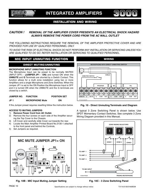
MICROPHONE INPUT UNMUTING FUNCTION<br />
The Microphone Input can be preset to be normally MUTED<br />
(INPUT OFF) - (JUMPER JP1 - ON) and turned ON when the<br />
UNMUTE and G Terminals are shorted by a Switch Contact. This<br />
function allows for a multi zone installation using two or more<br />
Amplifiers and a single Microphone and Zone Switches. When the<br />
Jumper JP1 is set to the ON Position the Microphone Input is OFF<br />
and it is turned ON when the UNMUTE and the G terminals are<br />
closed by a switch.<br />
MIC<br />
UNMUTING SWITCH<br />
SHIELD<br />
PROGRAM MIC TEL<br />
JUMPER NO. FUNCTION POSITION SET<br />
UNMUTE<br />
G<br />
MUTE<br />
G COM HOT G COM HOT G COM HOT<br />
JP 1 MICROPHONE Mute ON<br />
3115unmutswit00<br />
If the Jumper preset requires resetting follow the instruction below.<br />
ACCESS TO MUTING JUMPERS<br />
1) Remove Power Cord from AC Outlet.<br />
2) Remove the four screws on each side of the Amplifier securing<br />
the Top Cover to the Chassis.<br />
3) Lift Cover and carefully slide Cover out towards the rear.<br />
4) Locate the Main Amplifier Printed Board No.3130-1 attached<br />
to the front panel and behind the Controls.<br />
5) Set Jumpers as required.<br />
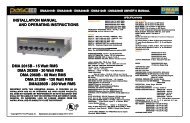
Fig. 10 - Direct Unmuting Terminals and Diagram<br />
A typical 3 Zone Switching Panel is shown below. Use<br />
SPDT Momentary Contact Switches. See complete 3 Zone<br />
Wiring Diagram provided in this Manual.<br />
ZONE PAGING SELECTORS<br />
1<br />
2 3<br />
MIC MUTE JUMPER JP1= ON<br />
ZONE 1<br />
ZONE 2<br />
ZONE3<br />
VR9<br />
VOX<br />
VOX<br />
JP1<br />
ON OFF<br />
JP2<br />
ON<br />
JP3<br />
OFF<br />
TO AMP 1<br />
TO AMP 2<br />
TO AMP 3<br />
ON<br />
OFF<br />
TO MIC INPUT<br />
3 Zone Panel<br />
PAGING MICROPHONE<br />
Fig. 10B - MIC Input Muting Jumper Setting<br />
Fig. 10C - 3 Zone Switching Panel<br />
PAGE 10 Specifications are subject to change without notice T3115/3130/3160BGM