Manuals - Paso Sound Products
Manuals - Paso Sound Products
Manuals - Paso Sound Products

You also want an ePaper? Increase the reach of your titles
YUMPU automatically turns print PDFs into web optimized ePapers that Google loves.
PROFESSIONAL AUDIO & SOUND<br />
®<br />
INTEGRATED AMPLIFIERS<br />
MESSAGES ON HOLD CONNECTIONS<br />
INSTALLATION AND WIRING<br />
Telephone<br />
600 ohm MOH System<br />
MOH<br />
Input<br />
600<br />
Ohm<br />
PROG<br />
AUX<br />
MOH SOURCE SELECTOR<br />
AWG 18 TWISTED PAIR<br />
INTERNAL MOH<br />
SOURCE JUMPER<br />
Telephone System<br />
KSU<br />
MOH OTPUT LEVEL CONTROL<br />
CAUTION; TO REDUCE THE RISK OF FIRE OR SHOCK DO<br />
NOT EXPOSE THIS APPLIANCE TO RAIN OR MOISTURE. DO<br />
NOT REMOVE COVER. THERE ARE NO USER<br />
SERVICEABLE PARTS INSIDE. REFER SERVICING TO<br />
QUALIFIED SERVICE PERSONNEL.<br />
117V 60 Hz<br />
500 W MAX.<br />
UNSWITCHED<br />
LINE FUSE<br />
1.6A 250 V<br />
3115 Repeat<br />
POWER RATING<br />
SUPPLY VOLTAGE<br />
POWER CONSUMPTION<br />
CAUTION: TO REDUCE THE RISK OF<br />
FIRE, REPLACE ONLY WITH<br />
SAMETYPE OF FUSE.<br />
ATTENTION: AFIN DE<br />
REDUIR LE RISQUE GROUND<br />
D©INCENDIE, REMPLACER<br />
SEUL PAR UN FUSIBLE<br />
DE MEME TYPE.<br />
ATTENTION: POUR REDUIRLES RISQUES D© INCENDIE<br />
OU DE CHOC ELECTRIQUE, NE PAS EXPOSER A LA<br />
PLUIE OU L©HUMIDITE, NE PAS ENLEVER LE<br />
COUVERCLE. AUCUN REGLAGE A L©INTERIEUR.<br />
POUR REPARATION CONSULTERUNE PERSONNE<br />
QUALIFIEE<br />
T3115BGM<br />
AMPLIFIER<br />
15 W RMS<br />
117V 60 HZ<br />
570 VA<br />
COM<br />
CLASS 2 WIRING ACCEPTABLE<br />
SER. NO.<br />
8 25V 70V<br />
AUX<br />
47K ohm 200 Mv<br />
IN PARALLEL<br />
MOH OUTPUT<br />
600 ohm 8 OHM MOH OUTPUT<br />
1 Volt 1 WATT LEVEL<br />
L<br />
R<br />
TEL OUTPUT<br />
LEVEL<br />
AUX<br />
ATTENUATOR<br />
10K OHM 250 OHM 600 OHM<br />
1 V<br />
1 MV 100 MV<br />
PROGRAM MIC TEL<br />
UNMUTE G MUTE G COM HOT G COM HOT G COM HOT<br />
BALANCED BALANCED BALANCED<br />
CENTER<br />
CONDUCTOR<br />
SHIELD<br />
MESSAGE REPEATER<br />
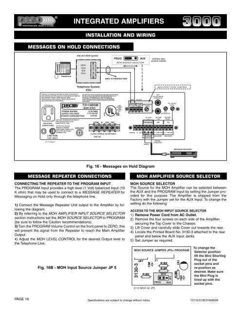
Fig. 16 - Messages on Hold Diagram<br />
MESSAGE REPEATER CONNECTIONS<br />
CONNECTING THE REPEATER TO THE PROGRAM INPUT<br />
The PROGRAM Input provides a high level (1 Volt) balanced Input (10<br />
K ohm) that may be used to connect to a MESSAGE REPEATER for<br />
Messaging on Hold only through the telephone line.<br />
1) Connect the Message Repeater Unit output to the Amplifier by following<br />
the diagram.<br />
2) By referring to the MOH AMPLIFIER INPUT SOURCE SELECTOR<br />
section instructions set the MOH SOURCE SELECTOR to PROGRAM<br />
(be sure to follow the Caution recommendations).<br />
3) Turn the PROGRAM Volume Control on the front panel to ZERO, this<br />
will prevent the signal from the Repeater to reach the Main Amplifier<br />
Output.<br />
4) Adjust the MOH LEVEL CONTROL for the desired Output level to<br />
the Telephone Line.<br />
Fig. 16B - MOH Input Source Jumper JP 5<br />
MOH AMPLIFIER SOURCE SELECTOR<br />
MOH SOURCE SELECTOR<br />
The Source for the MOH Amplifier can be selected between<br />
the AUX and the PROGRAM Input by setting the Jumper provided<br />
for this purpose. The Amplifier is shipped from the<br />
Factory with the Jumper set for the AUX Input. To change the<br />
setting do the following:<br />
ACCESS TO THE MOH INPUT SOURCE SELECTOR<br />
1) Remove Power Cord from AC Outlet.<br />
2) Remove the four screws on each side of the Amplifier<br />
securing the Top Cover to the Chassis.<br />
3) Lift Cover and carefully slide Cover out towards the rear.<br />
4) Locate the Printed Board No. 3130-3 attached to the rear<br />
panel and below the AUX Input Jacks.<br />
5) Set Jumper as required.<br />
MOH SOURCE JUMPER JP5= PROGRAM<br />
3130-3<br />
3115 MOH 02 JP5<br />
PROG<br />
MOH<br />
JP5<br />
AUX<br />
To change the<br />
Selector position<br />
lift the Mini Shorting<br />
Plug out of the<br />
socket pins and<br />
re-position as<br />
desired. Make sure<br />
the Mini Plug is<br />
lined up with the<br />
socket pins.<br />
PAGE 16 Specifications are subject to change without notice T3115/3130/3160BGM