Operation Manual - Thorvin Electronics
Operation Manual - Thorvin Electronics
Operation Manual - Thorvin Electronics

Create successful ePaper yourself
Turn your PDF publications into a flip-book with our unique Google optimized e-Paper software.
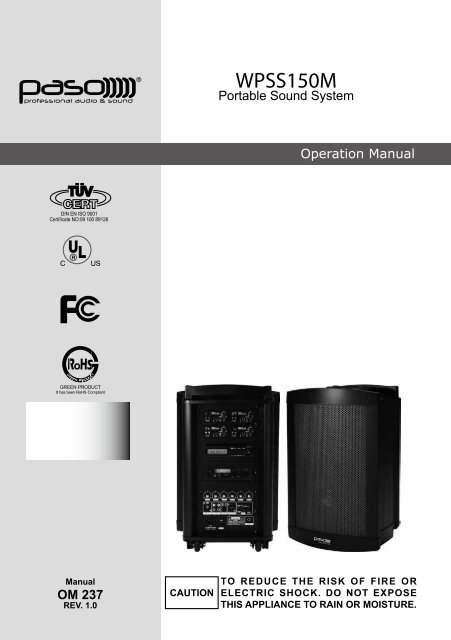
WPSS150M<br />
Portable Sound System<br />
<strong>Operation</strong> <strong>Manual</strong><br />
<strong>Manual</strong><br />
OM 237<br />
REV. 1.0<br />
CAUTION<br />
TO REDUCE THE RISK OF FIRE OR<br />
ELECTRIC SHOCK. DO NOT EXPOSE<br />
THIS APPLIANCE TO RAIN OR MOISTURE.
WPSS150M <strong>Operation</strong> <strong>Manual</strong><br />
Congratulations and thank you for the purchase of this all-in-one portable sound system. To<br />
ensure a trouble-free operation, please read the manual thoroughly to fully understand its<br />
controls and functions.<br />
WPSS150M can be installed with up to 4 receiver modules, among which one can be<br />
transmitter module. The wireless receiver/transmitter module can be in either UHF or VHF<br />
band and is a PLL synthesized type with 100 preset frequencies.<br />
Configuration :<br />
All versions of WPSS150M series come equipped with the following :<br />
1. AC power cord.<br />
2. 1~4 or no wireless receiver/transmitter module(s).<br />
3. 1~4 transmitters, either handheld or bodypack transmitter (except version with no<br />
module installed).<br />
Optional accessories :<br />
1. Weather proof dust cover.<br />
2. Tripod stand<br />
3. Companion powered speaker .(WPSS150S)<br />
4. Companion passive speaker.(PASS100)<br />
5. Wired microphone.<br />
Remarks:<br />
Remark: Manufacturer reserves the rights to change the above combinations without<br />
prior notice.<br />
-2-
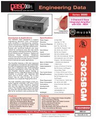
WPSS150M (Master, Basic configuration)<br />
A<br />
C<br />
A,B&D. Receiver modules<br />
C. Transmitter module<br />
B<br />
D<br />
1<br />
2 3 4 5 6<br />
7 8 9<br />
15<br />
10<br />
11<br />
12 13 14<br />
16<br />
1. MIC IN.<br />
2. LINE-IN VOL.<br />
3. DVD CONTROL<br />
4. BASS<br />
5. TREBLE<br />
6. MASTER VOL.<br />
7. MIC IN<br />
8. LINE IN / OUT<br />
9. VOICE PRIORITY<br />
10. ACTIVE OUT (MASTER OUT)<br />
11. BATTERY LOW LED<br />
12. CHARGING INDICATOR<br />
13. FUSE<br />
14. 24~32V DC-IN<br />
15. POWER<br />
16. EXT.SP<br />
-3-
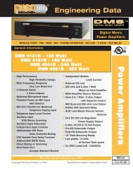
WPSS150M (Master, CD/USB player & Digital Recorder player version)<br />
1<br />
2 3 4 5<br />
6 7 8 9 10<br />
f g h i j<br />
11<br />
1. LCD DISPLAY<br />
2. PLAY/PAUSE<br />
3. STOP<br />
4. SKIP<br />
5. EJECT<br />
6. CD SELECTOR<br />
7. USB SELECTOR<br />
8. FOLDER SKIP<br />
9. IR LED<br />
10. USB INPUT<br />
11. POWER/VOL.<br />
a<br />
c<br />
d<br />
b<br />
e<br />
k<br />
o<br />
l<br />
p<br />
m n<br />
q<br />
a. POWER<br />
b. LCD DISPLAY<br />
c. EAR<br />
d. USB<br />
e. SD CARD SLOT<br />
f. LINE▲▼<br />
g. EQ<br />
h. REPEAT<br />
i. REWIND<br />
j. FORWARD<br />
k. REC<br />
l. STOP<br />
m. MODE.<br />
n. PLAY ll<br />
o. MIC VOL<br />
p. MIC IN<br />
q. VOL<br />
-4-
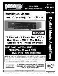
WPSS150S (LIMITED AVAILABILITY)<br />
The WPSS150S is an active (powered) speaker unit with built-in switching power supply<br />
as well as rechargeable batteries, complete with similar charging circuit as that of the<br />
WPSS150M Master unit.<br />
It is an extended and indispensable member of the WPSS150S Audio Link system.<br />
A<br />
B<br />
A. Slot for receiver module<br />
B. slot for receiver/transmitter module<br />
11<br />
18<br />
12<br />
19<br />
15 16<br />
20<br />
13<br />
17<br />
14<br />
11. SPEAKER OUT (SWITCHED)<br />
12. SPEAKER OUT<br />
13. 24-32V DC INPUT<br />
14. FUSE<br />
15. BATTERY LOW INDICATOR<br />
16. BATTERY STATUS INDICATOR<br />
17. CHARGING INDICATOR<br />
18. SLAVE IN<br />
19. SLAVE OUT<br />
20. SLAVE VOL.<br />
-5-
PASS100 Speaker<br />
The PASS100 Speaker is a passive companion speaker for the WPSS150M series.<br />
It is for connection to the switched or unswitched speaker outs of the WPSS150M (Master)<br />
or the PASS100 Slave units.<br />
22 23<br />
22. SPEAKER IN<br />
23. SPEAKER OUT<br />
-6-
Operating procedures<br />
After unpacking the unit for the first time, please charge the unit for about 4-5 hours before<br />
any operation. This is absolutely necessary as the built-in rechargeable battery might have<br />
been discharged naturally due to long shipment and storage time, even though it has been<br />
fully charged in the factory prior to shipment.<br />
To operate this portable sound unit, switch on the main POWER switch, the GREEN LED<br />
above it will glow. However, if the RED LED also glows at the same time, it means the<br />
battery is getting weak and a recharge of the battery is necessary.<br />
The main POWER switch does NOT switch on the Wireless receiver module and Tape/CD<br />
Player/Digital Recorder as each of them has dedicated Power / Volume control switch on<br />
its panel. To operate each of them, you must switch them on accordingly.<br />
Operating the dynamic wired microphone.<br />
To use a cable microphone, simply plug it into any MIC IN socket. The mic sockett accepts<br />
both phone and Cannon jack. Rotate the dedicated volume control knob and master<br />
volume control, amplified sound could be heard from the speaker when voice is spoken<br />
into the cable microphone.<br />
When a full range high fidelity sound is emphasized, the mode selector (3) should be put to<br />
MUSIC. For vocal frequencies where better clarity and projection is emphasized, put the<br />
mode selector to SPEECH and this will produce more mid-range frequency.<br />
Operating the Wireless Microphone System.<br />
To operate the wireless system, just switch on the power/volume control on the module<br />
panel and the matching transmitter. Please have the channel setting on both the transmitter<br />
and receiver module be the same before operation. Please as well make sure that master<br />
volume control is set to minimum level before turning the unit on, especially working on<br />
a wireless version! Set the Master volume control to the mid position. Rotate the volume<br />
control knob on receiver panel clockwise to the desired levels. When voice is spoken into<br />
the microphone, amplified sound should be heard over the built-in speaker.<br />
RM190U receiver module<br />
1. Channel Indicator<br />
2. Power switch/volume control<br />
3. Channel Selector<br />
4. Transmitter battery weak indicator<br />
5. Diversity A/B Indicator<br />
6. SCAN<br />
7. Squelch control<br />
1<br />
3<br />
4<br />
5<br />
2<br />
6 7<br />
-7-
First turn on the Power of the main unit. Then turn on the individual power of the RM190U<br />
receiver module. Select a desired channel by pressing the ▲ or ▼ button and the<br />
corresponding channel on the Transmitter.<br />
When transmitter is turned on, either A or B diversity indicator will flash to indicate that<br />
signal has been received. Turning the volume control in clockwise direction can increase<br />
the audio output. Once the power volume on the transmitter is too low, the LED indicator (4)<br />
on this panel grow will grow to remind.<br />
Frequency scanning<br />
It is the automatic scan function key. To perform the scan function, the transmitter must be<br />
switched off. Once the key is being pressed, the unit will do an auto scan and the next<br />
clean channel will be displayed. Change the transmitter channel setting to this setting for<br />
an interference- free operation.<br />
Squelch(SQ) setting<br />
When a channel is in use and undesired interference signal is received, turn the SQ<br />
in clockwise direction to make the receiver less sensitive and thus less susceptible to<br />
interference. If this still does not solve the problem, it means this frequency is not applicable<br />
at current position. Please switch over to the next channel.<br />
TM190 Transmitter module<br />
1 2<br />
3<br />
4<br />
5<br />
6<br />
1. Channel indicator<br />
2. Antenna socket(TNC type)<br />
3. Channel selectors: Press ▲(up)▼(down) to increase/decrease channel number. Please<br />
select a non-interfering frequency channel to those used in the receiver modules.<br />
4. Power on/off<br />
5. Audio sensitivity: Clockwise to increase its sensitivity level and anticlockwise to reduce.<br />
6. Output power switch. L for LOW output power and H for high output power. LOW output<br />
power will reduce the RF transmission distance and HIGH output power will extend the<br />
possible RF transmission distance.<br />
However, if TM190 is installed in portable amplifiers, HIGH output power will reduce<br />
more operation time than LOW output power since it requires more power for longer RF<br />
transmission.<br />
-8-
<strong>Operation</strong> of system with CD / USB Player.<br />
This operation is valid for version of WPSS150M with built-in "CD / USB Player" To operate,<br />
push the Power/Vol button to turn on the player. The LCD panel on the player will be lighted<br />
up and normal operation is ready. To insert a CD, just push it into the CD slot and the<br />
mechanism will suck it in automatically.<br />
Rotate the volume control knob to adjust the volume of the player. For Bass and Treble<br />
setting, adjust the individual Bass and Treble controls.<br />
For more details, please refer to the instruction on "CD / USB Player" controls and<br />
functions.<br />
<strong>Operation</strong> of system with Digital Recorder.<br />
This operation is valid for version of WPSS150M with built-in "Digital Recorder".<br />
To operate, first turn on the Master power switch and then press the designated power<br />
button of this module. The LCD display will be lighted up and Volume setting can be<br />
done by rotating the knob. For Bass and Treble setting, adjust the designated controls<br />
respectively.<br />
For more details, please refer to the instruction of "Digital Recorder" controls and functions.<br />
<strong>Operation</strong> of system with Tape Deck.<br />
This operation is valid for version of WPSS150M with built-in "Tape Deck".<br />
Rotate the volume control knob of the TAPE / CD control to adjust the volume of the Tape<br />
deck. For Bass and Treble setting, adjust the designated controls respectively.<br />
For more details, please refer to the instruction of "Tape Deck" Controls and functions.<br />
Voice Priority (Ducking) operation<br />
Voice Priority operation is only necessary when Cassette tape or CD is playing.<br />
When the Voice Priority switch (9) is put to ON position, the ducking function will be<br />
activated. While the music is playing, a voice input from either a Wired or Wireless<br />
Microphone will temporary override and turn down the volume of the background music<br />
and voice could be heard clearly.<br />
Background music will return to its original setting when no audio input is entering the<br />
microphone for a certain time. However, if the microphone is not switch off, the reentering<br />
of music into the microphone will also activate the voice priority function. So, Voice<br />
priority is best operated using microphones with on / off switch.<br />
However, in an aerobic operation, Voice Priority should NOT be activated !<br />
-9-
Wired Audio Link<br />
<br />
<br />
<br />
<br />
<br />
<br />
<br />
<br />
The WPSS150M could be operated as MASTER only. The WPSS150S can only be<br />
operated<br />
as SLAVE.<br />
In order to operate Audio Link, you must have a WPSS150M unit that operates as a<br />
MASTER. Only one unit is allowed to act as MASTER and the other(s) MUST operate as<br />
SLAVE(s). A MASTER unit is capable of connecting up to about 20 SLAVE units.<br />
To operate Audio Link, connect the Active Out (10) of the MASTER to the Audio Link IN (18)<br />
of the 1st SLAVE unit. The Out (19) of this SLAVE should be connected to the IN jack (18)<br />
of the 2nd SLAVE unit. Similar connection shall continue as such for the following SLAVE<br />
units.<br />
Volume Control (6) for MASTER or (20) for SLAVE.<br />
When used on the MASTER, it controls the MASTER as well as all the SLAVE units.<br />
When used on the SLAVE unit, it only controls that particular SLAVE unit volume.<br />
Maximum number of SLAVE units to be connected with a MASTER is about 20.<br />
Wireless Audio Link<br />
Different from Wired Audio Link, with new SLAVE's capability of installation of receiver<br />
and transmitter modules it eliminates all cable connection and largely extends the number<br />
limit of SLAVEs.<br />
One Master + several SLAVEs (with receiver and transmitter modules built in) : For crowds<br />
of over 3000.<br />
-10-
Application: For crowds of 1000 to 2000,<br />
ex.speeches or forums.<br />
Configuration: One Master + several<br />
SLAVEs (with receiver module built in)<br />
<br />
<br />
<br />
<br />
<br />
Application: For crowds of over ex.stadiums.<br />
Configuration: One Master + several<br />
SLAVEs (with receiver and transmitter<br />
module built in)<br />
<br />
<br />
<br />
<br />
<br />
<br />
<br />
<br />
<br />
<br />
<br />
<br />
<br />
<br />
<br />
<br />
<br />
T:Transmitter R: Receiver Channel:1,2,3,...<br />
T1 matches R1, T2 matches R2, T3<br />
matches R3, T4...<br />
<br />
<br />
<br />
Battery Charging<br />
Internally, the WPSS150M contains 2 pcs of 12V / 5AH maintenance free lead acid<br />
battery, which has no memory effect.<br />
When the batteries are weak, the power indicator (11) LED will keep lighted still. To<br />
charge the batteries, simply plug in the AC power supply, the charging process will start<br />
automatically. While charging, the charging indicator (12) will flash GREEN.<br />
When batteries are fully charged, the charging indicator (12) will keep lighted GREEN.<br />
External speaker (16)<br />
For audio output connection to another speaker system.<br />
-11-
Replacement of the covers of receiver module<br />
To identify different matches of receiver and transmitter, there are 4 extra sets of button<br />
covers with different colors available for replacement.<br />
<br />
<br />
<br />
<br />
<br />
<br />
<br />
<br />
<br />
<br />
<br />
-12-
Operating the CD / USB Player<br />
Front remotable is a unique feature of WPSS150M. User can easily control this CD player<br />
by clicking its remote from both front and rear WPSS150M.<br />
To begin operation switch on the CD Power after the main power of WPSS150M has been<br />
turned on.<br />
Keys<br />
Functions<br />
PLAY/PAUSE When this key is pushed during CD stop, play will start after track<br />
search.<br />
When this key is pushed during CD is playing, it will be changed to<br />
pause.<br />
When this key is pushed during CD is pausing, it will be changed to<br />
play.<br />
STOP<br />
When CD is not stop, if this key is pushed then CD will stop.<br />
CD<br />
When press this key will change to cd-mp3 mode.<br />
USB<br />
When press this key will changed to USB mode.<br />
SKIP+UP/CUE In stop mode:<br />
Change the starting play track (file) during stop mode, cyclic to the<br />
first track, if it is in the last track.<br />
In program entry mode:<br />
Change to the next track(file) for program select .<br />
In play mode, pause mode, program play mode, random play mode:<br />
Single pressed, skip the playing track (file) to next track(file) for normal<br />
play/pause mode, to next program index track(file) for program play/<br />
pause mode, to next random track(file) for random play /pause mode.<br />
Continue pressed , fast forward during play/pause when pressed more<br />
than 0.7sec.<br />
SKIP-DONW/REV In stop mode:<br />
Change the starting play track (file) during stop mode, cyclic to the<br />
last track, if it is in the first track.<br />
In program Entry mode:<br />
Change to the previous track (file) for program select.<br />
In play mode, pause mode, program play mode:<br />
Single pressed, skip the playing track (file) to precious track (file) for<br />
normal play/pause mode, to previous program index track (file) for<br />
program play/pause mode.<br />
Continue pressed, fast reverse during play/pause when pressed more<br />
than 0.7sec.<br />
FOLDER-UP In stop mode:<br />
Skip the starting play folder to next folder during stop mode, cyclic to<br />
the first folder if it is in the last folder.<br />
In program entry mode:<br />
Change the file for program select to next folder’s first file, cyclic to the<br />
first folder if it is in the last folder.<br />
In normal play mode:<br />
Skip the playing file to the next folder’s first file.<br />
-13-
FOLDER-DOWN In stop mode:<br />
Skip the starting play folder to previous folder during stop mode, cyclic<br />
to the last folder if it is in the first folder.<br />
In program entry mode:<br />
Change the file for program select to previous folder’s first file, cyclic<br />
to the last folder if it is in the first folder.<br />
In normal play mode:<br />
Skip the playing file to the previous folder’s first file.<br />
PLAY MODE In mp3 mode and in USB mode .<br />
If this key is pushed, PLAY mode is changed cyclically shown below.<br />
PLAY ALL RANDOM→REPEAT TRACK→REPEAT FOLDER→<br />
REPEAT ALL→RANDOM REPEAT→PLAY ALL<br />
IN CD mode If this key is pushed, PLAY mode is changed cyclically<br />
shown below.<br />
PLAY ALL RANDOM→REPEAT TRACK→REPEAT ALL→<br />
RANDOM REPEAT→PLAY ALL.<br />
EJECT<br />
When this key is pushed, door is moved out.<br />
PROG<br />
Set to programming mode.<br />
When programming mode, “stop” key is pushed then program is all<br />
cleared.<br />
MUTE<br />
When this key is pushed during CD is playing, the set will mute the<br />
output. Pushing again can recovery the output.<br />
POWER Power SW of the set.<br />
ESP<br />
In CDDA mode, Press ”ESP” key, The ESP display lighted and the set<br />
is in electronic anti-shock state. The electronic anti-shock time is about<br />
40 seconds. Press “ESP” key again, cancel the ESP function.<br />
FIND In MP3 mode : Press this key once FILE search mode changed .<br />
Press this key twice ALBUM search mode changed. Long press this<br />
key to display the track. Press twice to display ID3 TAG.<br />
0~10 You can use these keys to select the track you want directly.<br />
VOL.-<br />
When this key is pushed, the volume will decrease by 1dB per step,<br />
the min. volume is 0dB.<br />
VOL.+<br />
When this key is pushed, the volume will increase by 1dB per step, the<br />
max. volume is 30dB.<br />
Caution: This player does not accept 8-cm diameter CD. User is advised to have the USB 2.0<br />
formatted in “ FAT “ or “ FAT 32 “. The built-in USB 2.0 player can not be able to read the<br />
MP3 files stored in your USB if it is not formatted by either “ FAT “ or “ FAT-32 “. To avoid<br />
damage to the USB, remember to detach it only after switching off the player.<br />
-14-
UHF handheld transmitter MW295<br />
Parts and functions<br />
1. Microphone capsule module<br />
2. Battery status LED<br />
3. ON/OFF switch<br />
4. LCD<br />
5. Battery compartment<br />
6. Rotating protective cap for controls (also serves as color identification cap)<br />
7. Lock / Unlock<br />
8. Set<br />
9. Up<br />
10. Down<br />
11. Charging port<br />
1 2 3 4 5 6 10 7 11 8 9<br />
Battery installation<br />
MW295 microphone requires 2 AA-size batteries to operate. Please insert the batteries<br />
according to the correct polarity. Many batteries are known to have leakage problem of<br />
conductive and corrosive liquid. Please observe the rule to remove the batteries if they are<br />
not to be used for a longer period.<br />
Making changes to various settings in MW295<br />
1.Making changes to Channel:<br />
Use UP or DOWN button to go to the CHANNEL/ FREQUENCY page. The cursor will flash<br />
to allow changes to be made. Pressing UP or DOWN button will increase or decrease the<br />
channel number. The corresponding frequency will change accordingly. When a desired<br />
channel is selected, it will be automatically saved and stored in the memory.<br />
2. Making changes to Battery selection:<br />
Use UP or DOWN button to go to the Battery selection page.<br />
Press UP or DOWN button to move the cursor to either NiMH (rechargeable battery) or<br />
AKLN (Alkaline battery) position.<br />
When the desired battery has been selected, it will be automatically saved and stored in<br />
the memory.<br />
Remark : NiMH battery must be selected when rechargeable battery is being used. Never<br />
select AKLN (Alkaline) when transmitter is intended for charging as Alkaline battery can not<br />
be charged ! Wrong selection of battery will result in<br />
battery sensing electronics to display wrong and misleading status information.<br />
-15-
3. Making changes to Sensitivity Level:<br />
Use UP or DOWN button to go to the SENS SET page.<br />
Press UP or DOWN button to increase or decrease the Sensitivity Level of the transmitter.<br />
The MAX level is 4 and the MIN level is 1.<br />
When a desired sensitivity level has been selected for your application, it will be<br />
automatically saved and stored in the Memory.<br />
Remark : When selecting Sensitivity level, please bear in mind that Level 1 is for close<br />
proximity singing purposes whereas Level 4 is for use of transmitter on tripod mount for<br />
speech purposes. When Level 4 setting is used for close proximity singing, high SPL input<br />
will result in undesirable distortion in the output.<br />
After performing setting changes, you could turn the protective cover 180° in either<br />
direction to block the buttons from being accidentally adjusted.<br />
-16-
UHF beltpack transmitter MW293<br />
Parts and functions<br />
1. Antenna<br />
2. Battery weak / audio mute indicator<br />
3. Audio mute switch<br />
4. Mini-XLR connector<br />
5. Power ON / OFF switch<br />
6. LCD display<br />
7. Charging port<br />
8. Cover release button<br />
9. Charging contacts<br />
10. Lavalier microphone<br />
11. SET<br />
12. UP<br />
13. DOWN<br />
14. Gain control (GT, hign impedance)<br />
15. Gain control (MT, low impedance)<br />
1<br />
2 3 4<br />
5 6 7<br />
8<br />
10<br />
11<br />
14 15<br />
12 13<br />
9<br />
Battery installation<br />
MW293 microphone requires 2 AA-size batteries to operate. Please insert the batteries<br />
according to the correct polarity. Many batteries are known to have leakage problem of<br />
conductive and corrosive liquid. Please observe the rule to remove the batteries if they are<br />
not to be used for a longer period.<br />
Making changes to various settings in MW293<br />
1.Making changes to CHANNEL / FREQUENCY:<br />
Use UP or DOWN button to go to the CHANNEL /FREQUENCY page.<br />
The cursor will flash to allow changes to be made. Pressing UP or DOWN button will<br />
increase or decrease the channel number. The corresponding frequency will change<br />
accordingly. When a desired channel(frequency) is being selected, it will be automatically<br />
saved and stored in the memory.<br />
Remark : When changing transmitter frequencies, user should take care not to cause<br />
interference to other channels / users.<br />
-17-
2.Making changes to Battery selection:<br />
Use UP or DOWN button to go to the Battery selection page.<br />
Press SET for about 2 seconds to activate the cursor. Press UP or DOWN button to move<br />
the cursor to either NiMH (rechargeable battery) or AKLN (Alkaline battery) position.<br />
When the desired option has been selected, press SET for about 2 seconds to save and<br />
store the data in the memory.<br />
Remark : "NiMH" must be selected when rechargeable battery is being used. Never select<br />
"AKLN" (Alkaline) when transmitter is intended for charging as Alkaline battery can not be<br />
charged ! Wrong selection of battery will cause battery sensing electronics to display wrong<br />
information and mislead charging status.<br />
3.Input Level Gain Control Adjustment<br />
Low impedance (Lo-Z) " MT" & high impedance (Hi-Z) " GT" gain controls are situated<br />
inside the transmitter. Gain controls are adjustment ports that enable you to use<br />
microphones of differing output levels and Guitar or instruments with Hi-Z output. To<br />
adjust microphone (Lo-Z) input levels, turn the "MT" control and to adjust the Guitar or<br />
instrument (Hi-Z) input, adjust the "GT" gain control to set the transmitter's desired audio<br />
input level.<br />
FCC Caution<br />
To assure continued compliance, any changes or modifications not expressly approved<br />
by the party responsible for compliance could avoid the user's authority to operate this<br />
equipment. (Example - use only shielded interface cables when connecting to computer or<br />
peripheral devices.<br />
This device complies with Part 15 of the FCC Rules. <strong>Operation</strong> is subject to the following<br />
two conditions:<br />
(1)This device may not cause harmful interference, and<br />
(2)this device must accept any interference received, including interference that may cause<br />
undesired operation.<br />
-18-
Maintenance-free Lead Acid battery<br />
Guidelines for maintenance-free Batteries:<br />
1. Battery should operate at temperatures between 15°C ~ 50°C. To ensure a longer life<br />
span, it should be kept between 5°C ~ 35°C. For optimum result, 20°C ~ 25°C will be ideal.<br />
When temperature falls 15 degrees below zero, battery will undergo some changes in its<br />
chemical contents and therefore cannot be recharged. Operating the battery at higher<br />
temperature will result in higher capacity but shorter lifespan, whereas lower temperatures<br />
operation has a longer lifespan but less capacity.<br />
2. If the battery is not recharged 72 hrs after it is completely used, it will be permanently<br />
damaged.<br />
3. When the battery is being charged, the internal gases will be electrolyzed into water<br />
at the negative charge, maintaining the battery’s storage abilities with no water added.<br />
However, erosion at the charged ends of the battery will cause poor performance.<br />
4. The battery’s cycle lifespan (no. of charge and discharge cycle) is determined by the<br />
degree at which power is dissipated., especially the degree of discharged each time it is<br />
used and the recovery charging method. For normal use, the battery can be used for longer<br />
hours when less power is dissipated each time and vice versa. At 25°C, maintenance-free<br />
batteries could be charged 150 ~ 200 times at 100% discharge each time.<br />
5. Decrease in capacity, internal short circuit, deformation in appearance, erosion of<br />
charged ends and decrease in open circuit voltage are symbols indicating battery is<br />
approaching the end of its life cycle.<br />
6. When two batteries are used in parallel connection, the resistance of the cables should<br />
be kept equal.<br />
Properties of the Lead Acid Battery:<br />
1. Has no memory effect. Can be charged at anytime, even when the recharge indication<br />
light is not on.<br />
2. Performance and efficiency are affected by changes in the environment, especially<br />
temperature and humidity. (Best operated between 20°C ~ 25°C)<br />
3. Battery discharge naturally according to a certain pattern even not in use. For best<br />
performance and a prolonged lifespan, it should be recharged every month even when not<br />
in use.<br />
4. Under normal circumstances, battery could last for about a year.<br />
5. When the battery’s life expires, possible indicators include internal short-circuit, decrease<br />
in capacity, deformation in appearance, erosion of charged ends and decrease in operating<br />
voltage.<br />
User’s Precautions:<br />
1. For first-time use, charge the battery for 10 hrs until it is fully charged.<br />
2. To maintain performance and lifespan, if product has not been used for 3 months after<br />
the initial shipment, please fully charge the battery.<br />
3. Before each use, it’s advisable to charge the battery to its full capacity.<br />
4. The average lifespan of the battery is one year. The user is advised to change the<br />
battery after one year of use.<br />
5. The current consumption is in direct ratio with load current. The more current<br />
consumption, the less the operation time.<br />
-19-
REPLACEMENT PARTS<br />
Please provide complete information when you request<br />
replacement parts from either the Factory ora Paso Authorized<br />
Distributor. Be certain to include the Part Number and Description<br />
as it appears on the parts list, the Model Number of the unit and if<br />
possible the Serial Number and the date of purchase of the unit.<br />
Replacement parts inventory is maintained specifically to repair<br />
Paso products. Part sales for other reasons or applications will be<br />
declined.<br />
CUSTOMER SERVICE<br />
REPAIR SERVICE<br />
Repair service for out of warranty Paso products may be<br />
obtained form your local Paso distributor or any other<br />
qualified repair station.<br />
In warranty repairs must be returned to the Factory.<br />
Prior authorization must be obtained from the Factory.<br />
Products received without authorization will be refused by<br />
our Receiving Department.<br />
ORDERING FROM THE FACTORY<br />
Print all information ona purchase order form and mail to:<br />
PASO SOUND PRODUCTS, INC.<br />
4750 Goer Drive-Building F<br />
CHARLESTON, SC 29406<br />
Be sure to include the following:<br />
-Paso part number<br />
-Part description<br />
-Quantity required<br />
-Model number of the unit<br />
-Serial number of the unit<br />
-Your payment or your authorization for COD shipment for parts<br />
not covered by the Warranty or if your company hasa current<br />
account with the factory<br />
RETAIN ORIGINAL PARTS (IN WARRANTY) UNTIL YOU<br />
RECEIVE REPLACEMENTS. DEFECTIVE PARTS THAT<br />
SHOULD BE RETURNED TO THE FACTORY WILL BE LISTED<br />
ON YOUR PACKING SLIP.<br />
For your convenience replacement parts are also available through<br />
Paso Authorized Distributors and Dealers nation wide. Obtain a<br />
location list directly from the Factory or your regional Paso<br />
Representative.<br />
TECHNICAL CONSULTATION<br />
-Need help with your installation ?<br />
-Need help with the operation of the unit ?<br />
-Need help witha repair ?<br />
Call or write for assistance. You will find our Technical Dept. eager<br />
to help or assist you with any technical problem you may have<br />
encountered except “`Customizing'' fora unique application.<br />
The effectiveness of our consultation service depends on<br />
the accuracy of the information you furnish.<br />
Be sure to tell us:<br />
-The Model and Serial number of the unit<br />
-The date of purchase<br />
-An exact description of the difficulty<br />
-All trouble-shooting done in attempting to correct the problem<br />
Call our toll-free phone number:<br />
1-800 231 3034<br />
IN WARRANTY REPAIR SERVICE<br />
Call or write the Factory to obtain an authorization to<br />
return<br />
the product for repairs.<br />
Pack the equipment in the original carton or ina strong<br />
carton with at least THREE INCHES of resilient packing<br />
material on all sides, top and bottom. Seal the carton with<br />
reinforced tape and mark it FRAGILE on at least two<br />
sides. Remember, the Carrier will not accept liability for<br />
shipping damages if the unit is improperly packed.<br />
EQUIPMENT RECEIVED IN DAMAGED CONDITION<br />
DUE TO POOR PACKING WILL BE REFUSED AND<br />
THE WARRANTY COVERAGE IS AUTOMATICALLY<br />
VOIDED.<br />
The Paso Sound Limited Warranty provides:<br />
The examination of the returned product must disclose in<br />
our judgement,a manufacturing defect. The warranty<br />
does not extend to any product that has been subject to<br />
misuse, neglect, accident, improper installation or where<br />
the serial number of the product has been removed or<br />
defaced.<br />
Ship via insured prepaid United Parcel Service or Parcel<br />
Post to:<br />
PASO SOUND PRODUCTS, INC.<br />
4750 Goer Drive-Building F<br />
CHARLESTON, SC 29406<br />
ATTN. SERVICE DEPARTMENT<br />
The equipment will be returned freight prepaid after<br />
repairs.<br />
Be sure to include the following:<br />
-Your name and address<br />
-Date of purchase and copy of invoice<br />
-A brief description of the difficulty<br />
-A return address shipping label<br />
-<br />
OUT OF WARRANTY REPAIR SERVICE<br />
Follow return instructions as per in warranty repair<br />
service. Prior to performing all necessary repairs, you will<br />
be advised of the charges and at that timea written<br />
authorization by you will be required including<br />
authorization to return the equipment COD for the service<br />
and shipping charges. This will avoid unnecessary delays<br />
Web site: http://www.pasosound.com E-mail: info@pasosound.com<br />
475 0F Drive- Charleston, South Carolina 29406 / TEL: 1-800-231-3034 FAX: 843-308-0904<br />
Printed in ROC 2010<br />
Printed in USA 2010