Operators Manual - comPPage
Operators Manual - comPPage
Operators Manual - comPPage

Create successful ePaper yourself
Turn your PDF publications into a flip-book with our unique Google optimized e-Paper software.
INSTALLATION<br />
1. Insert CD-Rom into a CD-R or CD-RW drive.<br />
2 Auto Run will activate.<br />
3. If the Visual Basic files on your system are older than the ones being installed, the program will ask you if<br />
you want to update them. Answer YES. Reboot you system and start the install over.<br />
4. After the installation is complete you must configure the system before it will operate properly.<br />
SETUP<br />
1. Select [START], [PROGRAMS],[<strong>comPPage</strong> XLinks-TSI]<br />
You must register this software in order to activate and use it. The XLinks-TSI is a single user<br />
software.<br />
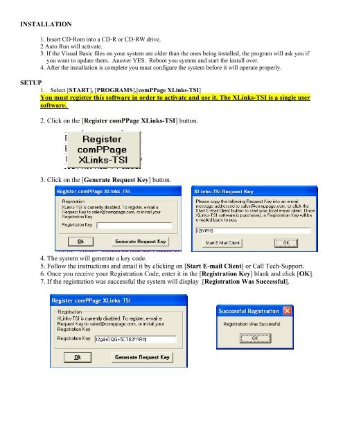
2. Click on the [Register <strong>comPPage</strong> XLinks-TSI] button.<br />
3. Click on the [Generate Request Key] button.<br />
4. The system will generate a key code.<br />
5. Follow the instructions and email it by clicking on [Start E-mail Client] or Call Tech-Support.<br />
6. Once you receive your Registration Code, enter it in the [Registration Key] blank and click [OK].<br />
7. If the registration was successful the system will display [Registration Was Successful].
Main Screen<br />
The main screen is where the user can select one of the following functions.<br />
1. [Exit] from program.<br />
2. Enter the XLinks-TSI configurations screen by selecting [Configure].<br />
3. Select to [Monitor] serial port activity.<br />
4. Select to activate the [Alarm] screen. All alarm activity on all serial ports<br />
will be displayed on the alarm screen. This includes supervisory alarms.<br />
When Configure is selected the following window will appear letting the user know processing will be disabled<br />
during configuration.
XLinks-TSI Configuration<br />
When CONFIGURE is selected from the main screen the below screen will appear. From this screen the<br />
user can select and configure all the systems input and output devices. Also on this screen the user will select<br />
general configurations; Log Transactions, Prompt for config password and Beep on Error Condition.<br />
XLinks-TSI has capability to monitor up to 4 Input communication ports simultaneously. The user can<br />
configure each input port independently for Translation/Repeats/Escalation.<br />
The XLinks-TSI Configuration screen is divided into 5 sections. Not all sections will be programmed for each<br />
Input. Section 5 is a global selection for all input configurations.
Input Communication Port Setup<br />
A. Input Configure (4 Inputs)<br />
1. Select [CONFIGURE] from main screen.<br />
2. Select [YES] for disabling processing data.<br />
3. Select [OK] for Com Port Not Configured.<br />
4. Select the communication port you want to use by clicking the circle next to the port.<br />
5. Select [ENABLE] and select the numbered communication port.<br />
6. Select [Configure Input COM Port]<br />
7. Configure the selected communication port and click [OK].<br />
8. Input 1 Serial Port Protocol, select [Type of Input].<br />
9. Select [Configure Input Protocol].<br />
Note: Prior to configuring the input protocol, you must have the output devices configured.<br />
All inputs will be configured the same way.
OutPut Device Configuration A-G<br />
A. <strong>comPPage</strong> PageConnect Client – Output to Radio Paging<br />
B. Internet E-Mail<br />
C. LED Message Boards<br />
D. Direct Serial TAP Protocol<br />
E. SNPP Protocol<br />
F. Spectralink<br />
G. Text to Speech - Option<br />
Select the output you want to use for your application by placing a check mark next to it, then click on the<br />
button next to it to configure that output.<br />
A. <strong>comPPage</strong> PageConnect Client<br />
(Must have <strong>comPPage</strong> PageConnect Server installed prior to selecting this option).<br />
Place a check mark next to [<strong>comPPage</strong> PageConnect Client].<br />
1. Click on the button [Configure Paging Server].<br />
2. In the [Server IP Address], enter the IP Address of the computer with the paging<br />
Server software and the paging transmitter is attached.<br />
3. Click [OK].<br />
B. Internet E-Mail<br />
1. Place a check mark next to [Internet E-Mail].<br />
2. Click on the button [Internet E-Mail].<br />
3. In the [Configure E-Mail Output], enter the SMTP Host that you will be using and follow<br />
The example below to fill in the fields that match your application. The SMTP Host will be<br />
The outgoing e-mail server provided by the internet service provider servicing the XLinks-<br />
TSI software installation location.<br />
4. You can customize the e-mail output format using the settings in the Configure E-Mail<br />
Output window. Once the configuration is made, use the [Test Mail Server] button to<br />
Ensure e-mail can be sent through the SMTP server.
C. LED Message Boards:<br />
1. Place a check mark next to [LED Message Boards].<br />
2. Click on the Button [Configure Message Board(s)].<br />
There are 3 Fields for Configuration for use with an LED Message Board(s):<br />
‣ Output Options<br />
‣ Message Display Configuration<br />
‣ Maintenance<br />
In the [Configure Message Board(s)] screen, you have these options:<br />
‣ To use as a [Wired Connection].<br />
‣ To use as a [Wireless connection] using a Paging Data Receiver, for delivery of the<br />
message to the Message Board(s).<br />
‣ To use [Message Routing] (routes messages by PIN value received on input port)<br />
‣ To use [Enunciation] via beeping at the console and/or the message board.<br />
3. Wired Connection<br />
► Choose the Com Port that the LED Message Board is attached to and<br />
configure the port.<br />
► Choose if you want to use [Message Routing].<br />
► Choose if you want to use [Enunciation].<br />
4. Wireless Connection<br />
This option allows you to send a message to the Paging Data Receiver (PDR)<br />
that is attached to the LED Message Board(s), via the Paging System.<br />
5. Message Routing<br />
This option allows you to associate a Pin Number to a Sign’s Address.<br />
6. Enunciation<br />
This option allows you to choose how you want to announce that a message has arrived.<br />
Note: If you are using a Wall Pager LED signs, you do not need to use this LED Message Board output<br />
feature, because the Wall Pager behaves just like a pager and does not require specialized messaging to<br />
control it.<br />
MESSAGE DISPLAY CONFIGURATION<br />
In the [Configure Message Board(s)] screen, you have these options:<br />
‣ Message “Quantity and Timing”<br />
‣ Message “Time Stamping”<br />
‣ Message “Formatting”<br />
‣ Message “Color Coding”<br />
‣ Message “Headers”
1. Message Quantity and Timing<br />
Set the number of messages you want the Message Board to display.<br />
Set the time when you want the message to clear from the display.<br />
2. Message Time Stamping<br />
Set the message to Display the Time of the Message and choose 12 or 24 Hour Format.<br />
3. Message Formatting<br />
Set the Sign Length, in character quantity, to allow the software to properly format nonscrolling<br />
messages.<br />
Set the Display Speed to how quickly you want the message to travel across the board.<br />
Choose whether you want to use the Hold Mode on long messages.<br />
Choose whether you want to have the message be left aligned or center aligned when<br />
displayed in hold mode.<br />
4. Message Color Coding<br />
Set the Display to show the color you want the message to be, per Input port. This<br />
feature, along with the Message Headers feature, allows you to identify the source<br />
of the message.<br />
NOTE: Must have a Tri-Color LED Message Board for this setting to have any effect.<br />
5. Message Headers<br />
Set the Display to include a message header with each message, per Input port. This<br />
feature, along with the Message Color Coding feature, allows you to identify the source<br />
of the message.<br />
MAINTENANCE<br />
In the “Configure Message Board(s)” screen, you have these options:<br />
‣ Test Message Boards<br />
‣ Clear Message Boards<br />
‣ Supervise Message Board wired connection<br />
Test Message Boards<br />
After configuring the system, you can TEST your Configuration by clicking on this button to send a<br />
message to the Message Board(s).<br />
Clear Message Boards<br />
You can CLEAR all messages from all Message Board(s), by clicking on this button.<br />
Supervise Message Board wired connection<br />
You can have the system Supervise the connection to wired Message Boards, by clicking on this button.<br />
If errors occur, they will be alerted and logged as supervisory errors in the XLinks-TSI software.
D. Direct Serial TAP Protocol.<br />
1. Place a check mark next to [Direct Serial TAP Protocol].<br />
2. Click on the Button [Configure Paging System(s)].<br />
‣ Configure the 1 st TAP Output com port<br />
‣ Configure the 2 nd TAP Output com port<br />
‣ Configure Routing for Undefined PIN Values (Default is “Discard”)<br />
‣ Configure the Com Port that is attached to the Paging System.<br />
‣ Click OK.<br />
Configure TAP Outputs<br />
Com Port Properties<br />
E. SNPP Protocol:<br />
1 Place a check mark next to [SNPP Protocol].<br />
2. Click on the Button [Configure SNPP Paging Server].<br />
3. Enter the SNPP Server Host Information that you will be using. SNPP servers are typically<br />
available from commercial paging services, as well as from TCP/IP capable on-site paging<br />
systems.<br />
4. You can Test the Configuration by clicking on the “Test SNPP Server” button.<br />
When completed, click “OK”.
F. Spectralink<br />
1. Place a check mark next to [Spectralink].<br />
2. Click on the Button [Configure Spectralink].<br />
3. Enter and Configure the com port that will be used with Spectralink Click [OK].<br />
G. Text to Speech<br />
This Option allows the Text Output that is delivered to a Pager to be converted to an Audio<br />
Announcement.<br />
You MUST Purchase the Text to Speech Option<br />
You MUST have an audio card and speakers installed in your PC.<br />
You MUST Download and Install the Voice Software Option, (Separate CD)<br />
1. Place a check mark next to [Configure Text to Speech].<br />
2. Click on the Button [Configure Text to Speech].<br />
3. Choose [ATT DTNV1.4 Crystal16]or [ATT DTNV1.4 Mike16] for the Output Voice<br />
from the Drop Down Menu.<br />
4. You may Enter a Text Message and Click the [TEST] Button to test the Voice Option.<br />
5. You may Choose how many times [1 to 3] that you want to repeat the Voice Output.
Recipient Configuration<br />
XLinks-TSI has 6 sets of [Recipients] that can be configured for use to fit your application.<br />
A. E-Mail Recipients<br />
B. Recipient Groups<br />
C. TAP Recipients<br />
D. SNPP Recipients<br />
E. Spectralink Recipients<br />
A. E-Mail Recipients<br />
1. In the [E-Mail Recipients Setup] Screen, enter the name and e-mail address of each recipient.<br />
2. Click the [ADD] button to add a recipient.<br />
3. Click the [TEST] button to test the Address you’ve setup.<br />
4. Click [EXIT] when finished.<br />
B. Recipient Groups<br />
1. In the [Recipient Groups] screen, you have 3 windows<br />
‣ Groups<br />
‣ All Recipients<br />
‣ Recipients In Group<br />
2. From this screen you will be able to assign Recipients to any Group(s).<br />
a. Click the [ADD] button to create a [Group], and give it a name.<br />
b. Highlight the [Group] that you want to add a Recipient to.<br />
c. Click on the [Recipient] name that you want to add to a recipient group.<br />
The name of All Recipients within a group will be shown in the [Recipients In Group] window. You can Add<br />
or Delete any Recipient within a group by clicking on the appropriate recipient. When finished, click [OK].
C. TAP Recipients<br />
1. In the [TAP Recipient Setup] screen, you can add, edit, or delete a recipient(s).<br />
2. Click the [ADD] button to add a recipient<br />
3. Click [EXIT] when finished.<br />
5. Fill in the Name and address of the recipient and click the [ADD] button. The Address value<br />
is also known as a PIN value.<br />
6. Click [END] when you are finished adding recipients.
D. SNPP Recipients<br />
In the [SNPP Recipients Setup] screen, you can add, edit, and delete recipients.<br />
1. Click the [ADD] button to add a recipient.<br />
2. Fill in the [Name] and [Address] of the recipient. The address is typically the<br />
PIN (personal Identification number) provided by the paging service.<br />
3. Click [End] when finished with each name.<br />
4. When all information has been added, click [Exit].<br />
E. Spectralink Recipients<br />
In the [Spectralink Recipients Setup] screen, you can add, edit and delete a recipient(s).<br />
1. Click the [ADD] button to add a recipient(s).<br />
2. Fill in the name and address of the recipient and click the [ADD] button. The Address value<br />
represents the Spectralink Handset ID.<br />
3. Click [END] when finished<br />
4. Click the [EXIT] button when finished.
Plain Text<br />
Key String Matching/Translation Protocol Interface Operation<br />
1. Select [Configure] from the Main Screen.<br />
Note: Serial Data Processing is DISABLED during configuration.<br />
2. Select [Plain Text] under Serial Port Protocol.<br />
3. Select [Key String Matching with Translation and Repeats]in Step 4.<br />
4. Click on [Configure Translation Table].<br />
5. In the [Configure Key String/Translation Inputs] screen Click on [Add].<br />
Check for Active or Inactive<br />
Enter Key String to look for and translate<br />
Enter Translation of Key string<br />
Select The Recipient to Receive the information<br />
Select The Recipient that will receive the<br />
Information if the record is escalated<br />
Enter the Reset information for this Record<br />
Enter the number of Repeats and the Interval<br />
If this Record needs to have a special time and<br />
Day for activation, Select Schedule and complete.<br />
Exit from configure screen<br />
Place Record below the selected record<br />
Insert Record at the end of file
6. After entering all data for each record select [EXIT]. The configure Key String screen will<br />
appear.<br />
Supervised Alarms<br />
All resets will be transmitted to the original and<br />
Escalation pager(s)<br />
Leave the Configuration screen<br />
Locate a specific Record<br />
Remove the record highlighted<br />
Change the data in the record highlighted<br />
Add a new Record<br />
If the [Translation String] field is blank, the information in the [Match String] field will be sent to<br />
the pager. No [Escalation or Repeat] will occur if you have not identified a [Reset String]. If the<br />
[RUR] is not checked, the point will repeat at the selected RP and RC once.<br />
CAUTION: The Reset String field can contain the same information for more than one input string.<br />
This means if you have more than on input string with the same reset information active at a time<br />
and the reset infomation is received, the wrong string could be reset. To ensure this does not<br />
happen, use unique reset or input strings when possible.<br />
7. When completed click on [EXIT]. This will return the user to the Main Screen.<br />
8. From the Main Screen select [ALARMS].
Inovonics<br />
The Inovonics module will translate the output of the FA403 decode receiver and process the date to the<br />
selected output device selected. Data must be inputted in the format show in this manual.<br />
1. Select [Configure] from the Main Screen.<br />
Note: Serial Data Processing is DISABLED during configuration.<br />
2. Select [Inovonics] under Serial Port Protocol.<br />
3. Click on [Inovonics Translation Routing]in Step 4.<br />
4. On the [Configure Inovonics Protocol] screen, click on [ADD].<br />
Check for Active or Inactive<br />
Enter Transmitter & System ID of the Wireless Tx<br />
Enter the information to be sent to the recipient for<br />
The transmitter entered above<br />
Select The Recipient to Receive the information<br />
Select The Recipient that will receive the<br />
Information if the record is escalated<br />
Enter the Reset character for the transmitter entered<br />
Above. w=Fixed transmitter, p=Pendant<br />
Enter the number of Repeats and the Interval<br />
If this Record needs to have a special time and<br />
Day for activation, Select Schedule and complete.<br />
Exit from configure screen<br />
Place Record below the selected record<br />
Insert Record at the end of file<br />
5. After entering all data for each record select [EXIT]. The configure Inovonics Protocol screen will<br />
appear.
6. At the bottom of the Configure Inovonics Protocol screen are special Global selections.<br />
OK Check in (health)<br />
Supervision of Transmitters<br />
Check in time.<br />
Page(s) if used, that supervision<br />
Alarms will be notified
Schedule Monitoring<br />
Each transmitter can be set to a schedule. When the schedule is selected the transmitter will be monitored for<br />
alarms during the period designated. If SCHEDULE , IS NOT selected, the transmitter will be monitored<br />
24/7. If an exception is required select one of the following. 1) Monitor All Day on Checked Days – If selected,<br />
the transmitter will be Monitored for alarms for 24 hrs on the day selected, disabling the selected time schedule.<br />
2.) Don’t Monitor on checked Days – If selected, the transmitter will not be monitored for alarms for 24 hrs on<br />
the day selected, disabling the selected time schedule.<br />
It should be noted NOT ALL transmitters should be scheduled. The chart below shows those transmitters that<br />
should not be scheduled. They should be monitored 24/7.<br />
FA205D<br />
FA536<br />
FA570<br />
FA575<br />
FA223S<br />
Belt Clip Pendant<br />
Locator<br />
Repeater Indoor<br />
Repeater Outdoor<br />
Pendant<br />
Tamper and Low Battery<br />
After identifying a pager in the Paging Software that you want to receive the TAMPER ALARM and LOW<br />
BATTERY alarm, select that pager at the bottom of the CONFIGURE screen labeled MAINTENANCE<br />
PAGER. Each time the TAMPER ALARM is detected from ANY transmitter identified in the ALERT<br />
XMITTER ID field, the message TAMPER ALERT XMITTER X, will be transmitted to the maintenance<br />
pager identified at the bottom of the screen.<br />
The TAMPER ALERT will be re-paged every 5 minutes until reset by correcting the tamper condition.<br />
The same is true for the LOW BATTERY ALERT. Both alerts will be logged and appear on the Alarm<br />
Screen. In order to clear the Low alert from the Alarm Screen, double click the alert or select the alert and<br />
click RESET At the bottom of the alarm screen.
Supervision<br />
The Inovonics interface software offers FULL SUPERVISON for all Inovonics Wireless<br />
Transmitter. Programming the check-in time of the wireless transmitters will be determined by the<br />
selection you make on the MONITOR CHECK-INs on the configuration screen. This selection is a<br />
global setting.<br />
Inovonics determines battery life on 60 second check-in. You should program your wireless<br />
transmitters according to the time that will be selected for the monitor check-in window. Remember<br />
some wireless transmitters are 2.5 times the programmed time. If you select a 60 second check-in for<br />
the FA223S/LT pendant, your actual check-in time would be approximately 3.5 minutes, allowing for<br />
20% drift. The 5 minute check-in window would accommodate this period. Remember, the larger<br />
amount of transmitters in the system will increase the amount of data the receiver must process.<br />
If the transmitter is going to be off site for a period of time you should go to that transmitter in the<br />
database and de-activate it by un-checking the ACTIVE box.<br />
- Select the time from the MONITOR CHECK-INs on the configure Inovonics screen the system<br />
will look for supervisory check in from all the transmitters in the system. See Chart below for<br />
recommendations.<br />
Check-In Interval Maximum Number of Transmitters Recommended Window<br />
30 Seconds 50 5 Minutes<br />
60 Seconds 100 1 Hours<br />
5 Minutes 200 2 Hours<br />
5 Minutes 300 – Above 4 Hours<br />
- If no alerts or check-ins have been received within the time frame selected on the configure<br />
Inovonics screen, a page stating [TRANSMITTER 10-1 OFF LINE] will be sent to maintenance<br />
pager selected and it will appear on the Alarm Screen. The page will be repeated every hour. (or<br />
time frame selected on the monitor check-in)<br />
- To correct the OFF-LINE condition perform one of the following actions.<br />
1. Access the transmitter in the database and un-check the active box.<br />
2. Bring the transmitter with-in range of the FA403 receiver.<br />
3. Replace battery if battery is bad.<br />
4. Reprogram transmitter to correct system ID and transmitter ID as shown in database.<br />
5. Correct entry in transmitter database if found to be in error.<br />
- To clear from Alarm Screen.<br />
1. Double Click the Transmitter that is off line and it will clear from the Alarm Screen.<br />
2. Select the Transmitter that is off line and Select RESET at the bottom of the Alarm<br />
Screen.
Locator<br />
If a Inovonics FA536 Locator is installed, the locator will receive alarm information from the wireless<br />
transmitters and relay it to the FA403 receiver with the location of the receiver plus the original alarm.<br />
The locator WILL NOT transmit signals from other Locators or Repeaters.<br />
Locator: Rec Room -Transmitter 10-1(pendant)<br />
Example: Original msg – Mrs. Smith Needs Assistance<br />
Locator msg – Mrs. Smith Needs Assistance Rec Room.<br />
Programming Chart – Example<br />
Tx/Sys Translation Pager Esc Reset<br />
1-1 Room 222 Bed Call (FA210) Wing 1 All Call w RP RC RUR<br />
2-1 Mrs. Smith Needs Assistance(FA223S/LTH) Wing 1 All Call P RP RC RUR<br />
3-1 Dining Room (FA536 Locator)<br />
4-1 Nurse Jones Needs Assistance(FA205D) All Call RP RC<br />
5-1 Room 222 Bath Call (FA210) Wing 1 All Call w RP RC RUR<br />
Note: Reset for FA210 Universal Transmitter should be [w]. Reset for all Pendants should be [p]<br />
TRANSMITTER SYSTEM ID’s USED 1 – 255. System ID 255 is used for Health check-in.<br />
Typical programming<br />
Transmitter Contact Supervision<br />
FA223/LTH N/O 5 Minutes<br />
FA205D N/O 60 Seconds (3.5 Minutes)<br />
FA210(M/W) N/O or N/C 5 Minutes<br />
External and Internal Contacts<br />
FA536 N/O 5 Minutes<br />
FA570<br />
5 Minutes<br />
Health Check-In<br />
The XLinks-TSI Inovonics module will automatically notify the staff if a resident has not checked in<br />
at a pre-set time. This function is only active if a Motion Detector has been programmed for System ID<br />
255 and the following information have been checked. Once the wireless transmitter has been properly<br />
Programmed, check the [OK Check in] on the Configure Inovonics Protocol screen.<br />
Click on [OK Check in Schedule] to schedule the time ALL the transmitters with SYSTEM ID 255<br />
will be active to generate an alarm. During the other time periods, the system will monitor for Tamper<br />
and Off-Line conditions.
Alarm Screen<br />
When the Plain Text and/or Inovonics module is selected and properly programmed the user can monitor all<br />
activity on the system using this screen. The Alarm Screen is split into two different areas. The top area is for<br />
monitoring Active Alarms and the bottom area is for Supervisory Alarms. The Alarm Screen is available no<br />
matter what output devise has been selected.<br />
When an alarm is triggered,<br />
the message to be sent to the<br />
output devise will appear<br />
here.<br />
If a Supervisory<br />
alarm is triggered it<br />
will appear here.<br />
Supervisory Alarm:<br />
Tamper<br />
Off-Line<br />
Low Battery<br />
Click to Exit from Screen<br />
Click to Force Reset alarms that does<br />
not automatically reset
Logging<br />
When the XLinks-TSI software is installed it will create a sub directory called [LOGS]. All operations of the<br />
will be logged, if the Log Transactions box on the XLinks-TSI configuration screen has been checked. The log<br />
will be given a file name of the Day, Month and year. A new file will be created each day. These logs can be<br />
view in any word processor program. The use can purchase a copy of <strong>comPPage</strong>’s LRG, Logging and Report<br />
Generating software, to view and create special reports.<br />
The log created by the ZLinks-TSI is a record of all operations of the program. It will record all pages, resets,<br />
both forced and program resets, escalations and timeout.<br />
Sample Log<br />
7:22 AM Application Started - 101302.log<br />
10/13/02 07:22 AM System Started<br />
<br />
10/13/02 07:26 AM PAGE ward nurse Room 210 Bed Call<br />
10/13/02 07:29 AM PAGE ward nurse Room 210 Bed Call - 1<br />
10/13/02 07:29 AM RESET ward nurse Room 210 Bed Call<br />
10/13/02 07:29 AM PAGE ward nurse Nurse Smith<br />
10/13/02 07:29 AM PAGE ward nurse Nurse Smith - 1<br />
10/13/02 07:29 AM RESET ward nurse Nurse Smith<br />
10/13/02 07:29 AM PAGE ward nurse Mrs. Jones Needs Assistance<br />
10/13/02 07:30 AM PAGE ward nurse Mrs. Jones Needs Assistance - 1<br />
10/13/02 07:31 AM PAGE ward nurse Mrs. Jones Needs Assistance - 2<br />
10/13/02 07:31 AM PAGE all call Mrs. Jones Needs Assistance - ESC<br />
10/13/02 07:32 AM PAGE ward nurse Mrs. Jones Needs Assistance - R<br />
10/13/02 07:32 AM RESET ward nurse Mrs. Jones Needs Assistance<br />
10/13/02 07:32 AM RESET all call Mrs. Jones Needs Assistance<br />
10/13/02 07:32 AM PAGE ward nurse Nurses Aid Jane Needs Assistance<br />
10/13/02 07:32 AM PAGE ward nurse Nurses Aid Jane Needs Assistance - 1<br />
10/13/02 07:32 AM RESET ward nurse Nurses Aid Jane Needs Assistance<br />
10/13/02 07:34 AM PAGE john-maint. TRANSMITTER ID 10-8 OFF LINE<br />
10/13/02 07:34 AM ERROR - Alert Mode Not Active for Transmitter ID 10<br />
10/13/02 07:43 AM PAGE ward nurse Room 210 Bed Call<br />
10/13/02 07:43 AM PAGE ward nurse Room 210 Bed Call Sun Deck<br />
10/13/02 07:43 AM RESET ward nurse Room 210 Bed Call Sun Deck<br />
10/13/02 07:43 AM PAGE ward nurse Mrs. Jones Needs Assistance<br />
10/13/02 07:43 AM PAGE ward nurse Mrs. Jones Needs Assistance Sun Deck<br />
10/13/02 07:44 AM PAGE ward nurse Mrs. Jones Needs Assistance Sun Deck - 1<br />
10/13/02 07:44 AM PAGE ward nurse Mrs. Jones Needs Assistance Sun Deck - 2<br />
10/13/02 07:45 AM PAGE all call Mrs. Jones Needs Assistance Sun Deck - ESC<br />
10/13/02 07:45 AM PAGE ward nurse Mrs. Jones Needs Assistance Sun Deck - R<br />
10/13/02 07:46 AM PAGE john-maint. TRANSMITTER ID 4-4 OFF LINE<br />
10/13/02 07:46 AM PAGE ward nurse Mrs. Jones Needs Assistance Sun Deck - 1R<br />
10/13/02 07:46 AM PAGE ward nurse Mrs. Jones Needs Assistance Sun Deck - 2R<br />
10/13/02 07:47 AM PAGE all call Mrs. Jones Needs Assistance Sun Deck - ESC/R<br />
10/13/02 07:47 AM RESET ward nurse Mrs. Jones Needs Assistance Sun Deck<br />
10/13/02 07:47 AM RESET all call Mrs. Jones Needs Assistance Sun Deck
General Configuration<br />
The following options are available.<br />
1. Log Transactions<br />
Place a check mark in the box and the program will log all actions.<br />
2. Prompt for Configuration password. [admin]<br />
Place a check mark in the box and the program will prompt you to enter<br />
the password when entering the configuration section of the program.<br />
3. Beep on Error Condition