1.2M Ku-BAND Rx/Tx SERIES 1134 ANTENNA SYSTEM - General ...
1.2M Ku-BAND Rx/Tx SERIES 1134 ANTENNA SYSTEM - General ...
1.2M Ku-BAND Rx/Tx SERIES 1134 ANTENNA SYSTEM - General ...

You also want an ePaper? Increase the reach of your titles
YUMPU automatically turns print PDFs into web optimized ePapers that Google loves.
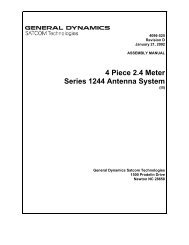
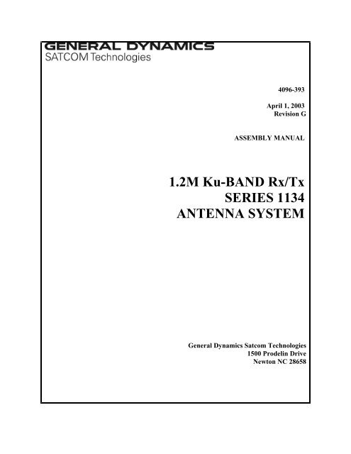
4096-393<br />
April 1, 2003<br />
Revision G<br />
ASSEMBLY MANUAL<br />
<strong>1.2M</strong> <strong>Ku</strong>-<strong>BAND</strong> <strong>Rx</strong>/<strong>Tx</strong><br />
<strong>SERIES</strong> <strong>1134</strong><br />
<strong>ANTENNA</strong> <strong>SYSTEM</strong><br />
<strong>General</strong> Dynamics Satcom Technologies<br />
1500 Prodelin Drive<br />
Newton NC 28658
<strong>1.2M</strong> <strong>Ku</strong>-<strong>BAND</strong> <strong>Rx</strong>/<strong>Tx</strong><br />
<strong>SERIES</strong> <strong>1134</strong> <strong>ANTENNA</strong> <strong>SYSTEM</strong><br />
G Revise Logo and name 4/17/09 RAH<br />
F Removed Feed from last paged 4/1/03 CLT<br />
E Revised Address 1/11/02 RAH<br />
D Revised per ECN2246 082197 PGW<br />
C Updated 3/18/97 PGW<br />
- ORIGINAL RELEASE 01/10/95 R Frye<br />
REV. DESCRIPTION DATE APPROVED
4096-393<br />
GENERAL DYNAMICS <strong>1.2M</strong> <strong>Ku</strong>-<strong>BAND</strong> <strong>Rx</strong>/<strong>Tx</strong> <strong>SERIES</strong> <strong>1134</strong><br />
2
4096-393<br />
GENERAL DYNAMICS <strong>1.2M</strong> <strong>Ku</strong>-<strong>BAND</strong> <strong>Rx</strong>/<strong>Tx</strong> <strong>SERIES</strong> <strong>1134</strong><br />
TABLE OF CONTENTS<br />
SECTION<br />
I<br />
TITLE<br />
INTRODUCTION<br />
1.0 GENERAL INFORMATION<br />
1.1 UNPACKING & INSPECTION<br />
1.2 FREIGHT DAMAGE<br />
1.3 MATERIAL MISSING OR DAMAGED<br />
1.4 MECHANICAL INSTALLATION TOOLS<br />
1.5 FOUNDATION INTERFACE<br />
II<br />
<strong>ANTENNA</strong> <strong>SYSTEM</strong> ASSEMBLY<br />
2.0 <strong>ANTENNA</strong> ASSEMBLY<br />
2.1 FEED ASSEMBLY<br />
III<br />
SATELLITE ALIGNMENT<br />
3.0 <strong>ANTENNA</strong> POINTING<br />
IV<br />
MAINTENANCE<br />
4.0 MAINTENANCE OVERVIEW<br />
4.1 REFLECTOR<br />
4.2 MOUNT & REFLECTOR SUPPORT<br />
4.3 FEED & FEED SUPPORT<br />
3
4096-393<br />
GENERAL DYNAMICS <strong>1.2M</strong> <strong>Ku</strong>-<strong>BAND</strong> <strong>Rx</strong>/<strong>Tx</strong> <strong>SERIES</strong> <strong>1134</strong><br />
SECTION I INTRODUCTION<br />
1.0 GENERAL INFORMATION<br />
This manual describes the assembly and installation of <strong>General</strong> Dynamics's 1.2 meter<br />
antenna system. The <strong>General</strong> Dynamics 1.2 meter is a rugged and reliable mount which<br />
will operate in the <strong>Ku</strong>-Band frequency with high efficiency and at the same time<br />
successfully withstand the effects of the environment.<br />
These instructions are listed by sections that cover all areas of assembly and installation.<br />
Additional sections are included in the manual to provide information on antenna<br />
alignment to the satellite and maintenance.<br />
1.1 UNPACKING AND INSPECTION<br />
The system containers should be unpacked and inspected at the earliest date to insure that<br />
all material has been received and is in good condition. A complete packing list for each<br />
major component is supplied.<br />
1.2 FREIGHT DAMAGE<br />
Any damage to materials while in transit should be immediately directed to the freight<br />
carrier. He will instruct you on matters regarding any freight damage claims.<br />
1.3 MATERIAL - MISSING OR DAMAGED<br />
Any questions regarding missing or damaged materials that is not due to the freight<br />
carrier should be directed to <strong>General</strong> Dynamics's Customer Service Department at:<br />
<strong>General</strong> Dynamics Satcom Technologies<br />
1500 Prodelin Drive<br />
Newton NC 28658<br />
USA<br />
(828) 464-4141<br />
4
4096-393<br />
GENERAL DYNAMICS <strong>1.2M</strong> <strong>Ku</strong>-<strong>BAND</strong> <strong>Rx</strong>/<strong>Tx</strong> <strong>SERIES</strong> <strong>1134</strong><br />
1.4 MECHANICAL INSTALLATION TOOLS<br />
The hardware supplied with this antenna system is U.S. SAE standard size and requires<br />
SAE wrench sizes. However, the sizes have been chosen to allow use with compatibly<br />
sized metric wrenches as shown in the table below.<br />
HARDWARE SIZE SAE WRENCH SIZE METRIC WRENCH<br />
SIZE<br />
MAXIMUM REC.<br />
TORQUE<br />
5/16” Bolt 1/2” 13 mm 12 ft-lbs<br />
(1.66 kg-m)<br />
1/2” Bolt 3/4” 20 mm 45 ft-lbs<br />
(6.20 kg-m)<br />
27/64” Screw 1/2” 13 mm Snug<br />
5/8” Bolt 15/16” 24 mm 85 ft-lbs<br />
(11.7 kg-m)<br />
Also recommended for installation:<br />
Inclinometer<br />
Compass<br />
Adjustable Wrench<br />
1.5 FOUNDATION INTERFACE<br />
The required interface from the foundation to the mount is 2-1/2" schedule 40 pipe (2.88"<br />
or 7.3 cm O.D.). A suggested in-ground foundation is shown in Figure 1.<br />
Also available from <strong>General</strong> Dynamics, as options, are a kingpost pedestal mount and a<br />
non penetrating mast mount.<br />
5
4096-393<br />
GENERAL DYNAMICS <strong>1.2M</strong> <strong>Ku</strong>-<strong>BAND</strong> <strong>Rx</strong>/<strong>Tx</strong> <strong>SERIES</strong> <strong>1134</strong><br />
SUGGESTED IN-GROUND FOUNDATION<br />
12.0<br />
(30.5 cm)<br />
30.0<br />
(76.2 cm)<br />
2.5” (6.4cm) SCH 40 PIPE<br />
2.88” OD (7.3 cm OD )<br />
SECTION A - A<br />
30.0<br />
(76.2 cm)<br />
SEE NOTE #7<br />
A<br />
A<br />
45<br />
NOTES:<br />
1. 2 1/2” schedule 40 pipe should conform with ASTM A53.<br />
2. All concrete should conform to building code standards and have a<br />
minimum compressive strength of 3000 PSI at 28 days. (Per ACI-318-77)<br />
3. Soil bearing capacity should be no less than 2000 PSF.<br />
4-. Concrete should be poured against undisturbed soil.<br />
5. Allow concrete 24 hours set time before installation of antenna.<br />
6. The antenna should be properly grounded to meet applicable local codes.<br />
7. Minimum depth as shown or extend to local frost line.<br />
8. Foundation meets the design requirements as set forth by the uniform building code. (1982 edition)<br />
(GENERAL DYNAMICS CORPORATION DOES NOT REPRESENT OR WARRANT THAT ANY<br />
PARTICULAR DESIGN OR SIZE OF FOUNDATION IS APPROPRIATE FOR ANY LOCALITY OR<br />
EARTH STATION INSTALLATION.)<br />
Figure 1.<br />
6
4096-393<br />
GENERAL DYNAMICS <strong>1.2M</strong> <strong>Ku</strong>-<strong>BAND</strong> <strong>Rx</strong>/<strong>Tx</strong> <strong>SERIES</strong> <strong>1134</strong><br />
PARTS LIST - <strong>1.2M</strong> <strong>ANTENNA</strong> ASSEMBLY<br />
ITEM NO. PART NO. DESCRIPTION QTY<br />
1 0181-585 Canister Assembly 1<br />
2 0181-584 Mount Assembly 1<br />
3 VARIES <strong>1.2M</strong> Reflector 1<br />
4 0490-203 Elevation Rod 1<br />
5 8104-007 1 / 2 - 13 Hex Nut<br />
2<br />
6 8319-006 Hi - Lo Screw<br />
4<br />
7 8031-008 5 / 16” x 1.00” Bolt<br />
2<br />
8 8031-012 5 / 16” x 1.50” Bolt<br />
1<br />
9 8201-041 5 / 16” Flat Washer<br />
4<br />
10 8202-041 5 / 16” Lock Washer<br />
3<br />
11 8101-009 5 / 16” Hex Nut<br />
3<br />
7
4096-393<br />
GENERAL DYNAMICS <strong>1.2M</strong> <strong>Ku</strong>-<strong>BAND</strong> <strong>Rx</strong>/<strong>Tx</strong> <strong>SERIES</strong> <strong>1134</strong><br />
SECTION II<br />
<strong>ANTENNA</strong> ASSEMBLY<br />
CAUTION: During the assembly procedure, the sequence of instructions must be<br />
followed. Do Not Tighten Any Hardware Until Instructed . Refer<br />
to the antenna assembly parts list and the steps shown below.<br />
2.0 <strong>ANTENNA</strong> ASSEMBLY<br />
STEP 1:<br />
Mount Assembly<br />
A). Remove azimuth tube from mount assembly.<br />
B). Set azimuth tube and hardware aside.<br />
Azimuth Tube<br />
Mount Assembly<br />
[ 7 ] [ 9,10,11 ]<br />
STEP 2:<br />
A). Insert 5 / 16” hardware ( items: 7,9,10, 11)<br />
thru hole on mount assembly as shown.<br />
Repeat on opposite side.<br />
8
4096-393<br />
GENERAL DYNAMICS <strong>1.2M</strong> <strong>Ku</strong>-<strong>BAND</strong> <strong>Rx</strong>/<strong>Tx</strong> <strong>SERIES</strong> <strong>1134</strong><br />
Remove<br />
Remove<br />
STEP 3;<br />
A). Remove rotation bolt, washer & lock washer<br />
and set aside.<br />
B). Remove [1] 1 / 2” jam nut.<br />
Canister<br />
Assembly<br />
Azimuth Rod<br />
Azimuth Rod<br />
STEP 4:<br />
A). Slide azimuth tube ( from Step. 1 ) onto<br />
azimuth rod.<br />
Azimuth Tube<br />
B). Replace 1 / 2” jam nut ( from Step. 3 ) back<br />
onto azimuth rod.<br />
1 / 2” Jam Nut<br />
STEP 5:<br />
To Satellite (within +/- 15 )<br />
A). Place the canister assembly onto mast pipe.<br />
B). Orient the canister assembly approximately<br />
towards the center of the satellite orbital arc<br />
to within +/- 15 .<br />
Canister Assembly<br />
C). Securely tighten [8] canister screws.<br />
D). Tighten [8] lock nuts against canister.<br />
Mast Pipe<br />
9
4096-393<br />
GENERAL DYNAMICS <strong>1.2M</strong> <strong>Ku</strong>-<strong>BAND</strong> <strong>Rx</strong>/<strong>Tx</strong> <strong>SERIES</strong> <strong>1134</strong><br />
6.0”<br />
(15.2 cm)<br />
[ 5 ]<br />
Elevation Rod<br />
STEP 6:<br />
A). Thread 1 / 2” nut (item 5) approximately<br />
6” (15.2 cm) onto elevation rod.<br />
Elevation Channel<br />
(on mount assembly)<br />
STEP 7:<br />
A). Insert elevation rod thru hole in elevation<br />
channel on mount assembly.<br />
B). Thread 1 / 2” nut (item 5) onto elevation<br />
rod.<br />
Elevation Rod<br />
[ 5 ]<br />
[ 9, 10, 11 ]<br />
[ 8 ]<br />
STEP 8:<br />
A). Attach elevation rod to the brackets on the<br />
back of the mount assembly with 5 / 16”<br />
hardware ( items: 8, 9, 10, 11 ).<br />
Mount Assembly<br />
B). Lightly tighten all hardware on the mount<br />
assembly at this time.<br />
10
4096-393<br />
GENERAL DYNAMICS <strong>1.2M</strong> <strong>Ku</strong>-<strong>BAND</strong> <strong>Rx</strong>/<strong>Tx</strong> <strong>SERIES</strong> <strong>1134</strong><br />
STEP 9:<br />
Mount Assembly<br />
A). Place the 1.2 meter reflector face down<br />
on a flat surface.<br />
Bottom of<br />
reflector<br />
B). Place the mount assembly onto the back<br />
of the reflector and orient as shown.<br />
C). Attach the mount assembly to the reflector<br />
with [4] HiLo screws ( item 6 ).<br />
D). Tighten securely but DO NOT over tighten<br />
as this may cause damage to the reflector.<br />
Reflector<br />
(face down)<br />
STEP 10:<br />
A). Place the reflector mount assembly<br />
(Step. 9) onto the canister assembly.<br />
Rotation<br />
Hardware<br />
(Step 3)<br />
B). Secure reflector mount assembly with<br />
rotation bolt, washer & lock washer<br />
from Step 3.<br />
11
4096-393<br />
GENERAL DYNAMICS <strong>1.2M</strong> <strong>Ku</strong>-<strong>BAND</strong> <strong>Rx</strong>/<strong>Tx</strong> <strong>SERIES</strong> <strong>1134</strong><br />
Hardware<br />
(Step 1)<br />
STEP 11:<br />
A). Adjust azimuth tube so that the tube will<br />
fit into the hole on the reflector mount<br />
assembly.<br />
B). Secure azimuth tube to the mount assembly<br />
with hardware set aside in Step 1.<br />
Azimuth<br />
Tube<br />
C). Tighten all hardware at this time.<br />
D). Follow instructions in Section II - 2.1 to<br />
install the feed supports.<br />
12
4096-393<br />
GENERAL DYNAMICS <strong>1.2M</strong> <strong>Ku</strong>-<strong>BAND</strong> <strong>Rx</strong>/<strong>Tx</strong> <strong>SERIES</strong> <strong>1134</strong><br />
2.1 FEED SUPPORT ASSEMBLY<br />
These instructions are intended as a general reference for feed support assembly. If<br />
your antenna system has specific feed support installation instructions, then refer to<br />
them at this time.<br />
PARTS LIST - <strong>1.2M</strong> FEED SUPPORT<br />
ITEM NO. PART NO. DESCRIPTION QTY<br />
1 VARIES Feed Rod 2<br />
2 VARIES Feed Support Tube 1<br />
3 8031-008 5 / 16” x 1.00” Bolt<br />
3<br />
4 8031-026 5 / 16” x 3.25” Bolt<br />
1<br />
5 8201-041 5 / 16” Flatwasher<br />
10<br />
6 8202-041 5 / 16” Lock Washer<br />
6<br />
7 8101-009 5 / 16” Hex Nut<br />
6<br />
8 8038-006 5 / 16” x .75” Carriage Bolt<br />
2<br />
13
4096-393<br />
GENERAL DYNAMICS <strong>1.2M</strong> <strong>Ku</strong>-<strong>BAND</strong> <strong>Rx</strong>/<strong>Tx</strong> <strong>SERIES</strong> <strong>1134</strong><br />
CAUTION: During the assembly procedure, the sequence of instructions must be<br />
followed. Do Not Tighten Any Hardware Until Instructed. Refer to the<br />
feed support parts list and the steps shown below.<br />
STEP 1:<br />
See Detail A<br />
A). Attach feed rods to reflector with<br />
( items: 3, 6, 7 ) and with [ 2 ] of<br />
( item 5 ).<br />
NOTE: The 2.00” flat end of the feed<br />
mounts to the outside rim of<br />
the reflector<br />
Feed Rods<br />
STEP 2:<br />
A). Mount feed support tube between the<br />
feed support brackets with [ 2 ] of<br />
( items: 8, 5, 6, 7 ).<br />
Feed Support Tube<br />
See Detail B<br />
14
4096-393<br />
GENERAL DYNAMICS <strong>1.2M</strong> <strong>Ku</strong>-<strong>BAND</strong> <strong>Rx</strong>/<strong>Tx</strong> <strong>SERIES</strong> <strong>1134</strong><br />
Feed Rod<br />
STEP 3:<br />
A). Connect the feed rods to the feed<br />
support tube with ( items: 4, 6, 7 )<br />
and with [ 2 ] of ( item 5 ).<br />
See Detail C<br />
Feed Support Tube<br />
STEP 4:<br />
A). Attach feed support tube to the<br />
reflector with ( items: 3, 6, 7 )<br />
and with [ 2 ] of ( item 5 ).<br />
B). Tighten the hardware at the reflector<br />
rim snugly ( Detail A ).<br />
Feed Support<br />
Tube<br />
See Detail D<br />
C). Tighten the hardware connecting<br />
the feed rods to the feed support<br />
tube ( Detail C ).<br />
D). Tighten the hardware that connects<br />
the feed support tube to the feed<br />
support brackets ( Detail B ).<br />
E). Tighten the hardware connecting<br />
the feed support tube to the reflector<br />
( Detail D ).<br />
F). Refer to separate instructions for the<br />
specific feed/ODU assembly to feed<br />
support.<br />
15
4096-393<br />
GENERAL DYNAMICS <strong>1.2M</strong> <strong>Ku</strong>-<strong>BAND</strong> <strong>Rx</strong>/<strong>Tx</strong> <strong>SERIES</strong> <strong>1134</strong><br />
DETAIL A<br />
[ 5 ]<br />
[ 5, 6, 7 ]<br />
[ 7 ]<br />
Reflector<br />
Feed Rod<br />
DETAIL B<br />
Feed Support<br />
Brackets<br />
[ 5, 6, 7 ]<br />
Feed Support Tube<br />
[ 5, 6, 7 ]<br />
DETAIL C<br />
[ 8 ]<br />
Feed Rod<br />
[ 5 ]<br />
[ 5, 6, 7 ]<br />
[ 4 ]<br />
Feed Support Tube<br />
DETAIL D<br />
Reflector<br />
Feed Support<br />
Bracket<br />
[ 5, 6, 7 ]<br />
[ 5 ]<br />
Feed Support Tube<br />
[ 3 ]<br />
16
4096-393<br />
GENERAL DYNAMICS <strong>1.2M</strong> <strong>Ku</strong>-<strong>BAND</strong> <strong>Rx</strong>/<strong>Tx</strong> <strong>SERIES</strong> <strong>1134</strong><br />
SECTION III <strong>ANTENNA</strong> POINTING<br />
3.0 <strong>ANTENNA</strong> POINTING<br />
The 1.2 meter reflector contains a 17.3° elevation offset look angle. Therefore, when<br />
the reflector aperture is perpendicular to the ground, the antenna is actually looking<br />
17.3° in elevation. Refer to Figure 2.<br />
Step 1: Place an inclinometer on the reflector support angle as shown in Figure 2.<br />
Step 2:<br />
Step 3:<br />
Step 4:<br />
Step 5:<br />
Adjust the reflector up or down in elevation by turning the two ½" hex nuts at the<br />
elevation channel until the desired elevation is read on the (inclinometer reading<br />
plus 17.3° = elevation angle). Note: Be sure that the elevation pivot hardware is<br />
loose enough to allow adjustment without damaging (bending) the elevation rod.<br />
Snug the hardware.<br />
Azimuth Adjustment: With the electronics set to acquire the satellite, rotate the<br />
antenna in azimuth until the satellite is found. Snug the azimuth adjustment<br />
hardware.<br />
Peak the antenna signal by fine adjustments made in both azimuth and elevation<br />
until the optimum signal is achieved.<br />
Tighten all hardware used for adjustment.<br />
17
4096-393<br />
GENERAL DYNAMICS <strong>1.2M</strong> <strong>Ku</strong>-<strong>BAND</strong> <strong>Rx</strong>/<strong>Tx</strong> <strong>SERIES</strong> <strong>1134</strong><br />
PLACE INCLINOMETER HERE<br />
ADJUST ELEVATION<br />
ADJUST AZIMUTH<br />
Figure 2<br />
18
4096-393<br />
GENERAL DYNAMICS <strong>1.2M</strong> <strong>Ku</strong>-<strong>BAND</strong> <strong>Rx</strong>/<strong>Tx</strong> <strong>SERIES</strong> <strong>1134</strong><br />
SECTION IV MAINTENANCE<br />
4.0 MAINTENANCE OVERVIEW<br />
After installation, the antenna requires only periodic inspection. It is anticipated<br />
that maintenance, if required, will be minimal and easily handled by a local or inhouse<br />
maintenance staff.<br />
4.1 REFLECTOR<br />
<strong>General</strong> Dynamics's reflector does not require any maintenance. The composite<br />
construction of the reflector is virtually impervious to any damages that could be caused<br />
by weather or atmospheric conditions.<br />
It is only necessary to inspect for any physical damage done by vandalism or very severe<br />
weather conditions.<br />
Should any damage be detected to a portion of the reflector, contact the Customer<br />
Service Department at <strong>General</strong> Dynamics for recommendations involving reflector<br />
repair.<br />
4.2 MOUNT AND REFLECTOR SUPPORT STRUCTURE<br />
The mount and reflector support structure supplied with this antenna is of steel<br />
construction and has a galvanized finish.<br />
If there are any signs of structural failure, the mount members that are damaged should be<br />
repaired or replaced.<br />
CORROSION: Any corrosion on steel members may be repaired with a cold, zinc-rich<br />
galvanizing paint.<br />
Note: Rust on the edges of stamped metal parts is normal and will not adversely<br />
affect the structural integrity of the antenna system.<br />
19
4096-393<br />
GENERAL DYNAMICS <strong>1.2M</strong> <strong>Ku</strong>-<strong>BAND</strong> <strong>Rx</strong>/<strong>Tx</strong> <strong>SERIES</strong> <strong>1134</strong><br />
4.3 FEED AND FEED SUPPORT<br />
The feed support and feed rods should be inspected to insure that all hardware is secure.<br />
The feed/radio mounting bolts should be tight.<br />
The feed horn window should be inspected to insure that it is intact so that no moisture<br />
can collect inside the feed horn.<br />
20
4096-393<br />
GENERAL DYNAMICS <strong>1.2M</strong> <strong>Ku</strong>-<strong>BAND</strong> <strong>Rx</strong>/<strong>Tx</strong> <strong>SERIES</strong> <strong>1134</strong><br />
<strong>General</strong> Dynamics Corporation<br />
Box contents for <strong>1134</strong> series, <strong>1.2M</strong> .8 F/D, basic antenna<br />
(Options to basic antenna not listed)<br />
Qty P/N Description<br />
1 0800-1366 <strong>1.2M</strong> .8 F/D Az/EL mount<br />
1 0181-584 assy, reflector support, <strong>1.2M</strong>, .8 F/D<br />
1 0181-585 assy, canister, <strong>1.2M</strong>, .8 F/D<br />
1 0490-203 weldment, elevation rod, <strong>1.2M</strong>, .8 F/D<br />
1 4096-393 instructions, <strong>1.2M</strong> .8 F/D Az/EL series <strong>1134</strong><br />
2 0200-320 kit, hardware, <strong>1.2M</strong> Az/EL mount<br />
4* 8319-006 screw, 27/64 - 13 x 1 3/8”, HL THD CTG<br />
1* 8031-012 bolt, HHCS, 5/16-18 x 1.50”, zinc w/ ultraguard<br />
4* 8201-041 flatwasher, 5/16, zinc w/ ultraguard<br />
3* 8202-041 lock washer, 5/16, zinc w/ ultraguard<br />
3* 8101-009 nut, HEX, 5/16-18, zinc w/ ultraguard<br />
2* 8104-007 nut, HEX, 1 / 2-13, zinc w/ ultraguard<br />
2* 8031-008 bolt, HHCS, 5/16-18 x 1.00”, zinc w/ ultraguard<br />
1 0800-1362 <strong>1.2M</strong> <strong>Rx</strong>/<strong>Tx</strong> reflector w/ <strong>Ku</strong> feed, .8 F/D<br />
1 0179-355 reflector, <strong>1.2M</strong> offset, <strong>Rx</strong>/<strong>Tx</strong>, .8F/D<br />
1 0200-604 kit, hardware (includes the following):<br />
1 0198-120 O ring, .962” I.D. x .067”<br />
1 0268-003 allen wrench, 7/64” short arm<br />
1 0432-036 grease silicon #3 pill<br />
7 8200-010 lock washer, #6, internal tooth, stainless steel<br />
7 8300-002 screw, SH, #6-32 x .50, stainless steel<br />
* Quantity per 0200-320, total count is twice the number indicated<br />
21