Two-Wire SuperDuct Duct Smoke Detector
Two-Wire SuperDuct Duct Smoke Detector
Two-Wire SuperDuct Duct Smoke Detector

Create successful ePaper yourself
Turn your PDF publications into a flip-book with our unique Google optimized e-Paper software.
GE<br />
Security<br />
FireworX Fire & Life Safety<br />
Conventional Initiating Devices<br />
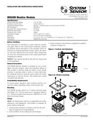
Overview<br />
<strong>Super<strong>Duct</strong></strong> is slim feature-rich alternative to bulky duct smoke<br />
detectors. Designed for easy installation and superb reliability,<br />
<strong>Super<strong>Duct</strong></strong> represents the perfect balance of practical design and<br />
advanced technology.<br />
<strong>Super<strong>Duct</strong></strong> detectors feature a unique design that speeds installation<br />
and simplifies maintenance. Removable dust filters, conformally<br />
coated circuit boards, and optional water-resistant gaskets keep<br />
contaminants away from components, ensuring years of troublefree<br />
service. When cleaning is required, the assemblies come apart<br />
easily and snap back together in seconds.<br />
<strong>Super<strong>Duct</strong></strong> detectors use differential sensing to prevent gradual environmental<br />
changes from triggering false alarms. A rapid change<br />
in environmental conditions, such as smoke from a fire, causes the<br />
detector to automatically signal an alarm condition but dust and<br />
debris accumulated over time does not change alarm sensitivity.<br />
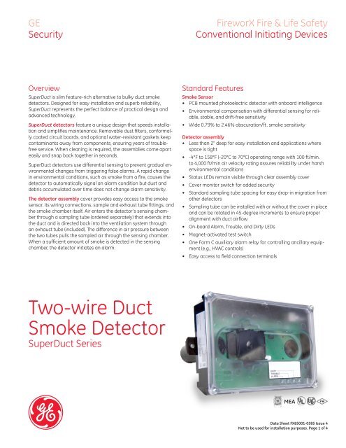
The detector assembly cover provides easy access to the smoke<br />
sensor, its wiring connections, sample and exhaust tube fittings, and<br />
the smoke chamber itself. Air enters the detector’s sensing chamber<br />
through a sampling tube (ordered separately) that extends into<br />
the duct and is directed back into the ventilation system through<br />
an exhaust tube (included). The difference in air pressure between<br />
the two tubes pulls the sampled air through the sensing chamber.<br />
When a sufficient amount of smoke is detected in the sensing<br />
chamber, the detector initiates an alarm.<br />
Standard Features<br />
<strong>Smoke</strong> Sensor<br />
• PCB mounted photoelectric detector with onboard intelligence<br />
• Environmental compensation with differential sensing for reliable,<br />
stable, and drift-free sensitivity<br />
• Wide 0.79% to 2.46% obscuration/ft. smoke sensitivity<br />
<strong>Detector</strong> assembly<br />
• Less than 2" deep for easy installation and applications where<br />
space is tight<br />
• -4°F to 158°F (-20°C to 70°C) operating range with 100 ft/min.<br />
to 4,000 ft/min air velocity rating assures reliability under harsh<br />
environmental conditions<br />
• Status LEDs remain visible through clear assembly cover<br />
• Cover monitor switch for added security<br />
• Standard sampling tube spacing for easy drop-in migration from<br />
other detectors<br />
• Sampling tube can be installed with or without the cover in place<br />
and can be rotated in 45-degree increments to ensure proper<br />
alignment with duct airflow<br />
• On-board Alarm, Trouble, and Dirty LEDs<br />
• Magnet-activated test switch<br />
• One Form C auxiliary alarm relay for controlling ancillary equipment<br />
(e.g., HVAC controls)<br />
• Easy access to field connection terminals<br />
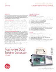
<strong>Two</strong>-wire <strong>Duct</strong><br />
<strong>Smoke</strong> <strong>Detector</strong><br />
<strong>Super<strong>Duct</strong></strong> Series<br />
MEA<br />
Data Sheet FX85001-0585 Issue 4<br />
Not to be used for installation purposes. Page of 4
Application<br />
The <strong>Super<strong>Duct</strong></strong> two-wire duct smoke detector is ideally suited to<br />
applications where early indication of combustion is required within<br />
the confined space of ventilation ductwork. Its primary purpose is<br />
to provide early warning of an impending fire and to prevent smoke<br />
from circulating throughout the building. It is typically used to<br />
detect smoke in the supply side of the HVAC system but can provide<br />
supervision of the return side as well.<br />
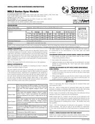
Assembly<br />
Sampling tube<br />
socket<br />
Exhaust tube<br />
Exhaust tube<br />
socket<br />
<strong>Detector</strong><br />
Protected premises<br />
Alarm relay<br />
output<br />
Remote<br />
test<br />
station<br />
Thin<br />
gasket<br />
Thick<br />
gasket<br />
Coupling<br />
HVAC<br />
unit<br />
FACP<br />
Alarm relay<br />
output<br />
<strong>Duct</strong> smoke<br />
detector<br />
<strong>Duct</strong> smoke<br />
detector<br />
Remote<br />
test<br />
station<br />
Return<br />
air<br />
Supply<br />
air<br />
Mounting<br />
Airflow<br />
Plug<br />
Sampling tube<br />
(ordered separately)<br />
HVAC duct<br />
<strong>Detector</strong><br />
<strong>Super<strong>Duct</strong></strong> detectors continually sample air flow in the HVAC duct<br />
and initiate an alarm condition whenever smoke is detected. An<br />
alarm is activated when the quantity (percent obscuration) of combustion<br />
products in that air sample exceeds the detector’s sensitivity<br />
setting.<br />
Sampling<br />
tube<br />
Air velocity in the duct as low as 100 ft/min. maintains adequate<br />
air flow into the sensor smoke chamber through air holes in the air<br />
sampling tube and discharges through the exhaust tube. <strong>Super<strong>Duct</strong></strong><br />
air sampling tubes must be installed with the inlet holes facing the<br />
airstream. Sampling tubes may be rotated in 45-degree increments<br />
so that air-holes can be aligned to allow the unit to be mounted in<br />
virtually any angle relative to the airflow.<br />
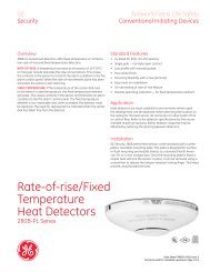
Dimensions<br />
8.70 in (22.1 cm)<br />
8.15 in (20.7 cm)<br />
7.75 in (19.7 cm)<br />
#10 sheet metal screw (2X)<br />
The sampling tube may be installed from either the duct side of the<br />
assembly or from inside the sensor compartment, as preferred by<br />
the installer. (The exhaust tube must be installed from the duct side.)<br />
Sampling tubes may be rotated in 45-degree increments so that<br />
air-holes can be aligned to allow the unit to be mounted at virtually<br />
any angle relative to the air flow.<br />
3.08 in (7.82 cm)<br />
1.60 in<br />
(4.06 cm)<br />
<strong>Super<strong>Duct</strong></strong> sensors are engineered to operate optimally under the<br />
harsh environmental conditions frequently found in HVAC ductwork.<br />
Nonetheless, before installing the detector, test the duct air velocity,<br />
temperature, and humidity to verify that it is within the operating<br />
range of the <strong>Super<strong>Duct</strong></strong> detector. Consult the <strong>Super<strong>Duct</strong></strong> installation<br />
sheet for details.<br />
2.28 in<br />
(5.78 cm)<br />
Remote Test, Reset, and Alarm Stations<br />
Labor-saving Remote Test/Reset stations<br />
provide alarm testing and indication from the<br />
convenience of a remote location. Tests can be<br />
performed quickly and safely – without having<br />
to climb to the roof. Magnetically-operated and<br />
key-operated one-gang models are available.<br />
<strong>Two</strong>-wire <strong>Super<strong>Duct</strong></strong> detectors are also compatible<br />
with EC-LED remote alarm LEDs.<br />
1.38 in<br />
(3.51 cm)<br />
5.40 in<br />
(13.72 cm)<br />
5.45 in<br />
(13.84 cm)<br />
1.90 in<br />
(4.83 cm)<br />
Data Sheet FX85001-0585 Issue 4<br />
Not to be used for installation purposes. Page of 4
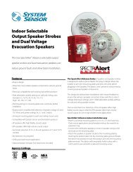
Wiring<br />
IDC short circuit current < 100 mA (Compatibility 0.0)<br />
Notes<br />
First device<br />
Last device<br />
[1] End-of-line resistor required on<br />
last controller only. Value is<br />
determined by the fire alarm control<br />
panel.<br />
17<br />
16<br />
Auxiliary<br />
equipment<br />
17<br />
16<br />
Auxiliary<br />
equipment<br />
[2] No more than one remote test<br />
stations can be connected at the<br />
same time. Wiring is nonsupervised.<br />
Maximum wire resistance is 10 ohms<br />
per wire.<br />
15<br />
14 4<br />
SD-TRK or SD-TRM [2]<br />
15<br />
14<br />
(3) Only the first detector to go into<br />
alarm operates its alarm relay.<br />
Operation of the alarm relay can't be<br />
guaranteed if a manual initiating<br />
device or other detector on the same<br />
circuit is activated.<br />
13 3<br />
12 2<br />
11 1<br />
Alarm<br />
13<br />
12<br />
11<br />
<br />
<br />
EC-LED [1]<br />
Alarm<br />
UL/ULC listed<br />
fire alarm<br />
control panel<br />
Initiating<br />
device<br />
circuit<br />
9 7<br />
10 8<br />
CAUTION<br />
Do not use looped wires under<br />
terminals 9 and 7, or 10 and 8.<br />
Break wire run to provide<br />
supervision of connections.<br />
9 7<br />
10 8<br />
EOLR [1]<br />
IDC short circuit > 100 mA (Compatibility 1.0)<br />
Notes<br />
First device<br />
Last device<br />
[1] End-of-line resistor required on<br />
last controller only. Value is<br />
determined by the fire alarm control<br />
panel.<br />
17<br />
16<br />
Auxiliary<br />
equipment<br />
17<br />
16<br />
Auxiliary<br />
equipment<br />
[2] No more than one remote test<br />
station can be connected at the same<br />
time. Wiring is nonsupervised.<br />
Maximum wire resistance is 10 ohms<br />
per wire.<br />
15<br />
14 4<br />
SD-TRK or SD-TRM [2]<br />
15<br />
14<br />
(3) Only the first detector to go into<br />
alarm operates its alarm relay.<br />
Operation of the alarm relay can't be<br />
guaranteed if a manual initiating<br />
device or other detector on the same<br />
circuit is activated.<br />
13 3<br />
12 2<br />
11 1<br />
Alarm<br />
13<br />
12<br />
11<br />
<br />
<br />
EC-LED [1]<br />
Alarm<br />
UL/ULC listed<br />
fire alarm<br />
control panel<br />
Initiating<br />
device<br />
circuit<br />
6 5<br />
10 8<br />
CAUTION<br />
Do not use looped wires under<br />
terminals 6 and 10, or 5 and 8.<br />
Break wire run to provide<br />
supervision of connections.<br />
6 5<br />
10 8<br />
EOLR [1]<br />
WARNING: <strong>Duct</strong> detectors have specific limitations. <strong>Duct</strong> detectors are not a<br />
substitute for an open area smoke detector. <strong>Duct</strong> detectors are not a substitute<br />
for early warning detection or a replacement for a building’s regular fire detection<br />
system. <strong>Smoke</strong> detectors are not designed to detect toxic gases which can build up<br />
to hazardous levels in some fires. These devices will not operate without electrical<br />
power. As fires frequently cause power interruptions, GE Security suggests you<br />
discuss further safeguards with your local fire protection specialist.<br />
Data Sheet FX85001-0585 Issue 4<br />
Not to be used for installation purposes. Page of 4
GE<br />
Security<br />
U.S.<br />
T 888-GESECURITY<br />
F 503-691-7566<br />
Canada<br />
T 519 376 2430<br />
F 519 376 7258<br />
Asia<br />
T 852 2907 8108<br />
F 852 2142 5063<br />
Latin America<br />
T 305 593 4301<br />
F 305 593 4300<br />
www.gesecurity.com/fireworx<br />
© 2009 General Electric Company<br />
All Rights Reserved<br />
Specifications, detector<br />
Dimensions<br />
<strong>Wire</strong> size<br />
Detection method<br />
Air velocity rating<br />
Air pressure differential<br />
Sensitivity<br />
Reset time<br />
Power up time<br />
Alarm test response time<br />
LED indicators<br />
Common alarm relay<br />
Operating voltage<br />
Operating current<br />
Alarm impedance<br />
Operating Environment<br />
Humidity<br />
Compatibility ID<br />
8.70 x 5.45 x 1.90 inches (221 x 138 x 48 mm)<br />
14 to 22 AWG<br />
Photoelectric (light scattering principle)<br />
100 to 4,000 ft/min and meets the required minimum air pressure differential<br />
0.005 to 1.00 inches of water<br />
0.79 to 2.46 %/ft obscuration<br />
1 second, max.<br />
30 seconds, max.<br />
5 seconds<br />
Alarm (red), Trouble (yellow), Dirty (yellow)<br />
Unsupervised and power-limited. Quantity: 1. Type: Form C.<br />
Ratings: 2.0 A at 30 Vdc (resistive)<br />
16 to 30 Vdc<br />
Startup: 200 µA. Standby: 70 µA. Alarm: 5 to 100 mA.<br />
50 to 750 Ohm<br />
Temperature (UL): -4 to 158 °F (-29 to 70 °C).<br />
Temperature (ULC): -4 to 120 °F (-29 to 49 °C)<br />
Relative humidity: 10 to 93%, noncondensing<br />
93% RH, noncondensing<br />
0.0: IDC short circuit current < 100 mA 0.0: IDC short circuit current<br />
= 100 mA 1.0: IDC short circuit current > 100 mA<br />
Specifications, test stations<br />
Remote Test/Reset Stations provide alarm test, trouble<br />
indication, and reset capability from a remote location.<br />
They include a one-gang plate, momentary SPST switch,<br />
red alarm LED, yellow trouble LED, and terminal block.<br />
Magnetically-operated models (TRM) or key-operated<br />
models (TRK) are available.<br />
Compatible<br />
electrical boxes<br />
LED indicators<br />
LED type<br />
<strong>Wire</strong> size<br />
Resistance per wire<br />
Current<br />
requirements<br />
LED circuit ratings<br />
Switch ratings<br />
(SD-TRK)<br />
Switch ratings (SD-<br />
TRM)<br />
Compatible<br />
detectors<br />
Operating<br />
environment<br />
Storage<br />
temperature<br />
North American 1-<br />
gang box Standard<br />
4-in square box, 1-1/2<br />
inches deep, with 1-<br />
gang cover<br />
Alarm (red)<br />
Clear lens<br />
12 to 22 AWG<br />
10 Ohms, max.<br />
See detector<br />
specifications<br />
Voltage: 3 Vdc, max.<br />
Current: 30 mA, max.<br />
Voltage: 125 Vdc, max.<br />
Current: 4 A, max.<br />
Voltage: 200 Vdc, max.<br />
Current: 0.5 A, max.<br />
<strong>Super<strong>Duct</strong></strong> conventional<br />
two-wire and instelligent<br />
duct smoke detectors<br />
Temperature: 32 to<br />
131 °F (0 to 55 °C)<br />
Humidity: 93% RH,<br />
noncondensing<br />
-4 to 140 °F (-20 to 60 °C)<br />
Ordering Information<br />
Catalog<br />
Number<br />
SD-2W<br />
Description<br />
Conventional<br />
<strong>Super<strong>Duct</strong></strong> <strong>Detector</strong><br />
Ship<br />
Wt. lb.<br />
(kg)<br />
2.4 (1.1)<br />
Accessories<br />
SD-T8 8-inch sampling tube 0.5 (0.2)<br />
SD-T18 18-inch sampling tube 1.5 (0.7)<br />
SD-T24 24-inch sampling tube 2.7 (1.2)<br />
SD-T36 36-inch sampling tube 3.0 (1.4)<br />
SD-T42 42-inch sampling tube 3.5 (1.6)<br />
SD-T60 60-inch sampling tube 5.8 (2.6)<br />
SD-T78 78-inch sampling tube 7.5 (3.4)<br />
SD-T120<br />
120-inch sampling 11.5<br />
tube<br />
(5.2)<br />
SD-TRM4<br />
Remote test station,<br />
magnetic<br />
1.0 (0.5)<br />
SD-TRK4<br />
Remote test station,<br />
keyed<br />
1.0 (0.5)<br />
EC-LED Remote LED indicator 1.0 (0.5)<br />
SD-VTK<br />
Air velocity test kit<br />
(stoppers only, etc)<br />
1.0 (0.5)<br />
SD-GSK Cover gasket kit 0.5 (0.2)<br />
SD-MAG Test magnet kit 0.5 (0.2)<br />
SD-2WPCB<br />
Replacement PCB,<br />
2-wire sensor kit<br />
1.0 (0.5)<br />
Data Sheet FX85001-0585 Issue 4<br />
Not to be used for installation purposes. Page of 4