

ASPIRE Spring 09 - Aspire - The Concrete Bridge Magazine
ASPIRE Spring 09 - Aspire - The Concrete Bridge Magazine
ASPIRE Spring 09 - Aspire - The Concrete Bridge Magazine

Create successful ePaper yourself
Turn your PDF publications into a flip-book with our unique Google optimized e-Paper software.
THE CONCRETE BRIDGE MAGAZINE<br />
SPRING 20<strong>09</strong><br />
www.aspirebridge.org<br />
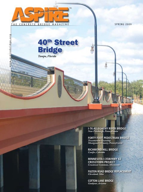
40 th Street<br />
<strong>Bridge</strong><br />
Tampa, Florida<br />
I-76 Allegheny River <strong>Bridge</strong><br />
Near Pittsburgh, Pennsylvania<br />
Forty Foot Pedestrian <strong>Bridge</strong><br />
Towamencin Township,<br />
Montgomery County, Pennsylvania<br />
RICHMOND HILL BRIDGE<br />
Conifer, Colorado<br />
MINNESOTA I-35W/Hwy 62<br />
CROSSTOWN PROJECT<br />
Crosstown Commons, Minnesota<br />
FULTON ROAD BRIDGE REPLACEMENT<br />
Cleveland, Ohio<br />
COTTON LANE BRIDGE<br />
Goodyear, Arizona
Bentley Solution for<br />
BriDges<br />
1<br />
2 3 4<br />
Deliver the BriDge You envisioneD<br />
<strong>Bridge</strong> engineering has advanced by leaps and bounds in recent years.<br />
Finally you can choose a single, comprehensive bridge software solution<br />
that can handle the state of your practice today.<br />
<strong>The</strong> Bentley ® bridge solution is at work worldwide on bridges of all<br />
types. From standard bridge projects with fairly consistent workflows to<br />
those with special engineering issues and problems, our software can<br />
meet virtually any bridge project need.<br />
<strong>The</strong>re are no dead ends in the process. Data is repurposed across<br />
analysis, design, engineering, fabrication, and construction – even<br />
rehabilitation. This greatly enhances collaboration and keeps all project<br />
stakeholders on the same page.<br />
1. Stonecutters <strong>Bridge</strong>, Hong Kong,<br />
Arup<br />
2. Ein Ha’Kore Interchange,<br />
Finley Engineering Group, Inc.<br />
3. West Gate Freeway, Australia<br />
Parsons Brinckerhoff<br />
4. I-15 NOW Project,<br />
Michael Baker Corporation<br />
Look to Bentley for unmatched software and services. Improve bridge<br />
project delivery. Control costs. Meet client expectations. Best of all,<br />
deliver the bridge you envisioned.<br />
We invite you to learn about Bentley’s bridge solution today. Visit<br />
www.bentley.com/bridges<br />
© 20<strong>09</strong> Bentley Systems, Incorporated. Bentley and the “B” Bentley logo are either registered or unregistered trademarks<br />
or service marks of Bentley Systems, Incorporated or one of its direct or indirect wholly owned subsidiaries. Other brands or<br />
product names are the properties of their respective owners.
Photo: PBS&J.<br />
Social, Economic, and Ecological Benefits<br />
of Sustainable <strong>Concrete</strong> <strong>Bridge</strong>s<br />
22<br />
8<br />
Features<br />
CONTENTS<br />
PBS&J Standardizing Success 8<br />
PBS&J creates innovative solutions by focusing on<br />
efficiency, constructability, and long life.<br />
I-76 Allegheny River <strong>Bridge</strong> 18<br />
New Pennsylvania Turnpike <strong>Bridge</strong> balances aesthetics,<br />
economy, and environmental sensitivity.<br />
Forty Foot Pedestrian <strong>Bridge</strong> 22<br />
Integrating Art and Engineering in Public Infrastructure.<br />
Richmond Hill <strong>Bridge</strong> 26<br />
Constant-depth bottom flanges on precast concrete<br />
U-girders were converted to a variable depth at the<br />
site to reduce fabrication and transportation costs.<br />
Minnesota I-35W/Hwy 62 Crosstown Project 30<br />
Precast segmental construction offered the most<br />
advantages and was the most attractive option.<br />
Fulton Road <strong>Bridge</strong> Replacement 34<br />
Cotton Lane <strong>Bridge</strong> 38<br />
Combination of local government and developers<br />
produces decorative, cost-efficient bridge design.<br />
Photo: Simone Collins Inc. Landscape Architecture.<br />
Photo: © FIGG.<br />
30<br />
Departments<br />
Editorial 2<br />
Reader Response 4<br />
<strong>Concrete</strong> Calendar 6<br />
Perspective—Sustainability<br />
Get In, Get Out, and Stay Out 14<br />
Aesthetics Commentary 33<br />
Safety and Serviceability 42<br />
<strong>Concrete</strong> Connections 44<br />
COUNTY—Lee County, Florida 46<br />
AASHTO LRFD Specifications 48<br />
Photo: State Highway 45 Interchange, PBS&J.<br />
Advertisers Index<br />
Bentley/LEAP .. . . . . . . . . . Inside Front Cover<br />
<strong>Bridge</strong> Software Institute.. . . . . . . . . . . . . 29<br />
Campbell Scientific.. . . . . . . . . . . . . . . . . . 43<br />
DSI. ................................ 7<br />
FIGG .. . . . . . . . . . . . . . . . . . . . . . . . . . . . . . . 3<br />
General Technologies Inc. .............. 4<br />
Headwaters Resources. ............... 48<br />
Larsa ............................... 5<br />
PB ................... Inside Back Cover<br />
PCAP—CABA.................. Back Cover<br />
PCI. ............................41, 45<br />
Shuttlelift........................... 13<br />
Simone Collins Inc. ................... 25<br />
Splice Sleeve. ....................... 47<br />
T.Y. Lin International .. . . . . . . . . . . . . . . . . 21<br />
ThyssenKrupp........................ 17<br />
Williams Form Engineering Corp......... 17<br />
<strong>ASPIRE</strong>, <strong>Spring</strong> 20<strong>09</strong> | 1
EDITORIAL<br />
Photo: Ted Lacey Photography.<br />
John S. Dick, Executive Editor<br />
As <strong>ASPIRE</strong> goes to press, the American<br />
Recovery and Reinvestment Act of 20<strong>09</strong> (also<br />
known as the Stimulus Act) has been signed into<br />
law. Whether it will accomplish its intended purpose<br />
remains to be seen. However, one thing is certain:<br />
A great many highway and bridge projects will get<br />
underway very soon. Many of these bridges will be<br />
constructed with concrete components, for a range of<br />
good reasons.<br />
An early assessment indicates some $26.6 billion<br />
will be apportioned to the states for “highways and<br />
bridges.” <strong>The</strong>se funds are in addition to contract<br />
authority provided in FY 20<strong>09</strong> and FY 2010. <strong>The</strong><br />
rules are specific concerning percentages of funds<br />
that need to be obligated by the agencies within a<br />
specified period of time, time frames for start-up and<br />
completion of projects, and so forth. But that is beyond<br />
the scope of our concern here.<br />
What is important to understand is that the<br />
concrete industry is poised to respond to this potential<br />
flood of demand. Responsiveness always has been<br />
a hallmark of the industry, and it was especially<br />
important during recent natural disasters and over<br />
the past several years when the supply of construction<br />
materials was erratic at best.<br />
<strong>The</strong> owner agencies have increasingly turned to<br />
concrete solutions. In 2008, the Federal Highway<br />
Administration (FHWA) reported statistics taken from<br />
the 2005 National <strong>Bridge</strong> Inventory (NBI), the most<br />
recent year for which complete data are available.<br />
For all new and replaced bridges constructed that<br />
year, concrete constituted a 65.5% share based on<br />
the area of decks. Based on the numbers of bridges,<br />
concrete accounted for 76.2% of bridges built in 2005.<br />
This percentage has continued to increase through<br />
the years.<br />
<strong>The</strong>re are many reasons for the growth of concrete<br />
bridges in the United States. Some of these include:<br />
Precast/Prestressed<br />
<strong>Concrete</strong> Institute<br />
American Coal Ash<br />
Association<br />
Stimulus Act and the<br />
Benefits of <strong>Concrete</strong> <strong>Bridge</strong>s<br />
1<br />
American Segmental<br />
<strong>Bridge</strong> Institute<br />
Expanded Shale Clay<br />
and Slate Institute<br />
Portland Cement<br />
Association<br />
Silica Fume<br />
Association<br />
• Wide-spread use of high performance concrete,<br />
which provides increased confidence in<br />
exceptional long-term performance.<br />
• Freedom from routine maintenance and its<br />
interference with traffic.<br />
• Improved efficiencies in construction methods<br />
and in the production of materials, and<br />
products—resulting in lower unit costs.<br />
• Confidence concerning supply and relative price<br />
stability.<br />
• Exciting solutions that expand the range of<br />
applications for concrete.<br />
• Sensitivity to creating sustainable solutions.<br />
• Capability for a wider range of aesthetic<br />
expressions.<br />
• <strong>The</strong> ability to meet ever-increasing demand<br />
to construct quickly, with improved quality, to<br />
reduce the duration of work-zone interference.<br />
<strong>ASPIRE</strong> is dedicated to bringing to its readers, a<br />
broad spectrum of real solutions that illustrate the<br />
benefits achieved with concrete bridges across a wide<br />
range of challenges, geographies, and stakeholders.<br />
This issue features examples of how concrete can<br />
be used for long-span bridges or short-span bridges;<br />
highway bridges or pedestrian overpasses; and<br />
interstate bridges, urban bridges, or rural bridges.<br />
We hope the stimulus program helps you to<br />
produce more bridges in the coming year, and we<br />
hope our efforts at <strong>ASPIRE</strong> give you new ideas for how<br />
to meet those needs quickly, cost effectively, and in<br />
aesthetically pleasing ways.<br />
We value your opinion about how we are<br />
succeeding. We invite you to share your impressions<br />
and comments about <strong>ASPIRE</strong> magazine with us. You<br />
can send an email from www.aspirebridge.org, or even<br />
better, fill out the quick survey reached by selecting<br />
the “Survey” button at www.aspirebridge.org. It offers<br />
multiple-choice and fill-in-the-blank questions. It’ll<br />
take less than 5 minutes to complete.<br />
Log on NOW at www.<br />
aspirebridge.org<br />
and take the <strong>ASPIRE</strong><br />
Reader Survey.<br />
Executive Editor: John S. Dick<br />
Managing Technical Editor: Dr. Henry G.<br />
Russell<br />
Managing Editor: Craig A. Shutt<br />
Editorial Staff: Daniel C. Brown, Roy Diez<br />
Editorial Administration: James O. Ahtes Inc.<br />
Art Director: Mark Leader, Leader Graphic<br />
Design Inc.<br />
Layout Design: Marcia Bending, Leader<br />
Graphic Design Inc.<br />
Electronic Production: Chris Bakker,<br />
Jim Henson, Leader Graphic Design Inc.<br />
Ad Sales: Jim Oestmann<br />
Phone: (847) 838-0500 • Cell: (847) 924-5497<br />
Fax: (847) 838-0555<br />
joestmann@arlpub.com<br />
Reprint Sales: Mark Leader<br />
(847) 564-54<strong>09</strong><br />
e-mail: mark@leadergraphics.com<br />
Publisher:<br />
Precast/Prestressed <strong>Concrete</strong> Institute,<br />
James G. Toscas, President<br />
Editorial Advisory Board:<br />
Susan N. Lane, Portland Cement Association<br />
(PCA)<br />
John S. Dick, Precast/Prestressed <strong>Concrete</strong><br />
Institute (PCI)<br />
William R. Cox, American Segmental <strong>Bridge</strong><br />
Institute (ASBI)<br />
Dr. Henry G. Russell, Managing Technical Editor<br />
POSTMASTER: Send address changes<br />
to <strong>Aspire</strong>, 2<strong>09</strong> W. Jackson Blvd., Suite 500,<br />
Chicago, IL 60606. Standard postage paid at<br />
Chicago, IL, and additional mailing offices.<br />
<strong>Aspire</strong> (Vol. 3, No. 2), ISSN 1935-2<strong>09</strong>3 is<br />
published quarterly by the Precast/Prestressed<br />
<strong>Concrete</strong> Institute, 2<strong>09</strong> W. Jackson Blvd., Suite<br />
500, Chicago, IL 60606.<br />
Copyright 20<strong>09</strong>, Precast/Prestressed <strong>Concrete</strong><br />
Institute.<br />
If you have a project to be con sidered for <strong>Aspire</strong>,<br />
send information to <strong>Aspire</strong>,<br />
2<strong>09</strong> W. Jackson Blvd., Suite 500,<br />
Chicago, IL 60606<br />
phone: (312) 786-0300<br />
www.aspirebridge.org<br />
e-mail: info@aspirebridge.org<br />
Cover:<br />
40th Street <strong>Bridge</strong>, Tampa, Fla.<br />
Photo: PBS&J.<br />
2 | <strong>ASPIRE</strong>, <strong>Spring</strong> 20<strong>09</strong>
I-76 Allegheny River <strong>Bridge</strong><br />
near Pittsburgh, PA<br />
Owner:<br />
Pennsylvania Turnpike<br />
Commission<br />
Designer: FIGG<br />
Contractor:<br />
Walsh Construction Company<br />
Creating <strong>Bridge</strong>s As Art ©<br />
Pennsylvania’s<br />
Longest <strong>Concrete</strong><br />
Segmental Span<br />
An Environment Friendly <strong>Bridge</strong><br />
Pennsylvania’s first<br />
balanced cantilever bridge<br />
provides an aesthetically<br />
pleasing and environment<br />
friendly crossing for<br />
Turnpike customers.<br />
Long spans of 285’, 380’,<br />
380’, 444’, 532’, and 329’<br />
and curved piers with<br />
stone texturing are<br />
in harmony with the site.<br />
Environment sensitive design<br />
protects aquatic habitats<br />
and preserves<br />
archeological areas.<br />
Completion planned<br />
for early 2010.<br />
Join the firm whose<br />
customers have received over<br />
300 design awards for<br />
sustainability, cost-efficiency,<br />
speed of construction and<br />
aesthetic beauty. If you share<br />
our passion for creating bridges<br />
as art ® , please contact us at<br />
1-800-358-3444.<br />
www.figgbridge.com<br />
An Equal Opportunity Employer
Bothe l, Washington<br />
READER RESPONSE<br />
T H E C O N C R E T E B R I D G E M A G A Z I N E<br />
w w w . a s p i r e b r i d g e . o r g<br />
WINTER 20<strong>09</strong><br />
Canyon Park<br />
Freeway Station <strong>Bridge</strong><br />
Editors,<br />
Again thank you for the opportunity to contribute<br />
to your magazine. <strong>The</strong> latest issue was terrific.<br />
William Collins, vice president<br />
Simone Collins Inc. Landscape Architecture<br />
Berwyn, Pa.<br />
Editor,<br />
<strong>ASPIRE</strong> is my favorite technical magazine!<br />
Tim Shell<br />
KPFF<br />
Portland, Ore.<br />
Editor,<br />
I am an editor in CH2M HILL’s Boise office. I<br />
would like to download the PDF of the article<br />
on Rainbow <strong>Bridge</strong> and link to it in our office<br />
newsletter. John Hinman, the author, is in our<br />
office.<br />
Eric Oden<br />
CH2M HILL<br />
Boise, Idaho<br />
Editors,<br />
I’ve had a couple people comment to me in<br />
the last few days about how much they like<br />
<strong>ASPIRE</strong>. You guys are obviously doing something<br />
right.<br />
Fred Gottemoeller, principal<br />
<strong>Bridge</strong>scape<br />
Columbia, Md.<br />
Editor,<br />
Just wanted to say “Thanks !!” for sending<br />
us the copies of the <strong>ASPIRE</strong> magazine that<br />
includes the NH article. It is well presented<br />
and formatted, and I was glad to see that the<br />
photos were clear and sharp. Thanks for the<br />
opportunity of having NH prepare an article<br />
for <strong>ASPIRE</strong>.<br />
Mark W. Richardson,<br />
Administrator, <strong>Bridge</strong> Design Bureau<br />
NH Department of Transportation<br />
Concord, N.H.<br />
MAPLE AVENUE BRIDGE<br />
Redmond, Oregon<br />
FOLSOM LAKE CROSSING<br />
Folsom, California<br />
KANAWHA RIVER BRIDGE<br />
Kanawha County, West Virginia<br />
PORT COLUMBUS<br />
INTERNATIONAL AIRPORT<br />
CROSSOVER TAXIWAY BRIDGE<br />
Columbus, Ohio<br />
Editor,<br />
“…wanted to let you know we thought the<br />
article turned out great (“Custom Arches,”<br />
<strong>ASPIRE</strong>, Winter 20<strong>09</strong>, p.18). Our engineer<br />
in particular was pleased. He was especially<br />
excited about the Aesthetics Commentary<br />
by Frederick Gottemoeller who ‘got what we<br />
were trying to do.’ Mr. Gottemoeller really<br />
understood our objectives and expressed them<br />
so well.”<br />
OBEC Consulting Engineers<br />
Eugene, Ore.<br />
4 | <strong>ASPIRE</strong>, <strong>Spring</strong> 20<strong>09</strong>
LET LARSA 4D TAKE YOUR PROJECTS INTO THE NEXT<br />
DIMENSION<br />
LARSA 4D is advanced structural analysis and design<br />
software specializing in bridges. <strong>The</strong> LARSA Macro Interface<br />
is an open system allowing clients to customize the program<br />
according to their needs.<br />
PBS&J uses LARSA 4D for staged construction and timedependent<br />
analysis, utilizing macros to accelerate the<br />
process of modeling and design.<br />
Clients turn to LARSA 4D for cable-stayed, segmental, and<br />
other advanced bridge projects. <strong>The</strong> software is the company<br />
standard at leading engineering and design firms including<br />
FIGG, HDR, International <strong>Bridge</strong> Technologies, and Parsons<br />
Brinckerhoff.<br />
I-4/Lee Roy Selmon Connector Interchange in Hillsborough County, Florida designed by PBS&J using LARSA 4D<br />
DESIGN ANALYSIS CONSTRUCTIOND<br />
LARSA 4
CONTRIBUTING AUTHORS<br />
Dr. Dennis R. Mertz is<br />
professor of civil engineering<br />
at the University of Delaware.<br />
Formerly with Modjeski and<br />
Masters Inc. when the LRFD<br />
Specifications were first written,<br />
he has continued to be actively<br />
involved in their development.<br />
Craig Finley is founder and<br />
managing principal of Finley<br />
Engineering Group Inc. (FINLEY),<br />
a bridge and construction<br />
engineering firm based in<br />
Tallahassee, Fla. A two-time<br />
winner of the ASBI Leadership<br />
Award, Finley has participated on some of the most noted<br />
precast segmental projects of the last 25 years.<br />
Frederick Gottemoeller<br />
is an engineer and architect,<br />
who specializes in the aesthetic<br />
aspects of bridges and<br />
highways. He is the author<br />
of <strong>Bridge</strong>scape, a reference<br />
book on aesthetics and was deputy administrator of the<br />
Maryland State Highway Administration.<br />
April 20-21, 20<strong>09</strong><br />
20<strong>09</strong> ASBI Grouting Certification Training<br />
J.J. Pickle Research Campus<br />
<strong>The</strong> Commons Center, Austin, Tex.<br />
April 22-26, 20<strong>09</strong><br />
PCI Committee Days<br />
Westin Hotel, Chicago, Ill.<br />
May 4-7, 20<strong>09</strong><br />
World of Coal Ash (WOCA 20<strong>09</strong>)<br />
Lexington Convention Center, Lexington, Ky.<br />
CONCRETE CALENDAR 20<strong>09</strong>/2010<br />
May 11-15, 20<strong>09</strong><br />
PCI Quality Control & Assurance Schools, Levels I, II & III<br />
Certified Field Auditor and Industry Erection Standards Schools<br />
Sheraton Music City Hotel, Nashville, Tenn.<br />
May 31, 20<strong>09</strong><br />
<strong>The</strong> Fifth International Conference on <strong>Bridge</strong> Maintenance, Safety and Management<br />
Abstracts due May 31, 20<strong>09</strong>, for IABMAS2010, to be held July 11-15, 2010<br />
Loews Philadelphia Hotel, Philadelphia, Pa.<br />
June 14-19, 20<strong>09</strong><br />
International <strong>Bridge</strong> Conference<br />
David L. Lawrence Convention Center, Pittsburgh, Pa.<br />
For links to websites, email addresses,<br />
or telephone numbers for these events,<br />
go to www.aspirebridge.org.<br />
June 15, 20<strong>09</strong><br />
fib International Congress (hosted by PCI)<br />
Abstracts due June 15, 20<strong>09</strong>, for this event, to be held May 29-June 2, 2010<br />
Gaylord National Resort & Convention Center, National Harbor, Md.<br />
July 5-9, 20<strong>09</strong><br />
AASHTO Subcommittee on <strong>Bridge</strong>s and Structures Annual Meeting<br />
Hilton Riverside Hotel, New Orleans, La.<br />
September 13-16, 20<strong>09</strong><br />
PCI-FHWA National <strong>Bridge</strong> Conference<br />
Marriott Rivercenter Hotel and Henry B. Gonzales Convention Center, San Antonio, Tex.<br />
MANAGING<br />
TECHNICAL EDITOR<br />
Photo: Ted Lacey Photography.<br />
Dr. Henry G. Russell is an engineering consultant,<br />
who has been involved with the applications of concrete in<br />
bridges for over 35 years and has published many papers<br />
on the applications of high performance concrete.<br />
September 21-23, 20<strong>09</strong><br />
Western <strong>Bridge</strong> Engineer’s Seminar<br />
Sacramento Convention Center and Sheraton Grand Hotel, Sacramento, Calif.<br />
October 25-27, 20<strong>09</strong><br />
20<strong>09</strong> ASBI 21st Annual Convention<br />
Hilton Hotel, Minneapolis, Minn.<br />
November 8-12, 20<strong>09</strong><br />
ACI Fall Convention<br />
Marriott New Orleans, New Orleans, La.<br />
January 10-14, 2010<br />
Transportation Research Board Annual Meeting<br />
Marriott Wardman Park, Omni Shoreham, and Hilton Washington, Washington, D.C.<br />
6 | <strong>ASPIRE</strong>, <strong>Spring</strong> 20<strong>09</strong>
1<br />
AMERICAN SEGMENTAL BRIDGE INSTITUTE<br />
Mark Your Calendar Today!<br />
For these two important 1 events.<br />
April 20-21<br />
20<strong>09</strong> Grouting Certification Training<br />
J.J. Pickle Research Campus<br />
University of Texas, Austin<br />
<strong>ASPIRE</strong> <strong>Concrete</strong> Construction03_20<strong>09</strong>.eps 19.02.20<strong>09</strong> 11:20:17<br />
October 25-27<br />
20<strong>09</strong> ASBI Convention<br />
Hilton Minneapolis<br />
For further details visit www.asbi-assoc.org<br />
11425_ASBI_<strong>ASPIRE</strong>_win<strong>09</strong>.indd 1<br />
12/10/08 1:08:43 PM<br />
RELY ON DSI<br />
Owners and contractors attach great importance to the fastest<br />
possible completion of structures. DYWIDAG Post-Tensioning<br />
Systems are the perfect solution for the construction industry.<br />
Our innovative, high-quality DYWIDAG Systems are<br />
world-renowned for their reliability and performance. DSI is<br />
the global market leader in the development, production and<br />
supply of DYWIDAG Post-Tensioning Systems. In line with<br />
our strong service-approach, we are always committed to<br />
satisfying our customers’ demands.<br />
DYWIDAG Bonded<br />
Post-Tensioning Systems<br />
DYWIDAG Unbonded<br />
Post-Tensioning Systems<br />
Local Presence – Global Competence<br />
POST-TENSIONING SYSTEMS<br />
www.dsiamerica.com<br />
Headquarter Construction America<br />
DYWIDAG-Systems<br />
International USA, Inc.<br />
320 Marmon Drive<br />
Bolingbrook, IL 60440, USA<br />
Phone (630) 739-1100<br />
dsiamerica@dsiamerica.com<br />
External Prestressing<br />
Stay Cable Systems<br />
with Bars<br />
DYNA Bond ® Stay Cable<br />
Systems<br />
Business Unit Post-Tensioning & Reinforcement<br />
320 Marmon Drive<br />
Bolingbrook, IL 60440, USA<br />
Phone (630) 972-4055<br />
Contact: Melissa Mariano<br />
2154 South Street<br />
Long Beach, CA 90805, USA<br />
Phone (562) 531-6161<br />
Contact: Ron Giesel<br />
1801 N. Peyco Drive<br />
Arlington, TX 76001, USA<br />
Phone (817) 465-3333<br />
Contact: Rafael Gomez<br />
4732 Stone Drive, Suite A<br />
Tucker, GA 30084, USA<br />
Phone (770) 491-3790<br />
Contact: Gary Pueschel<br />
168 Mary Reed Road<br />
Baden, PA 15005, USA<br />
Phone (724) 869-0155<br />
Contact: Joe Salvadori<br />
Structural Repair Solutions<br />
Contact: Marc Tessier Contact: Andy Hauter<br />
Phone (202) 263-4601 Phone (630) 972-4024<br />
DYNA Grip ® Stay Cable<br />
Systems<br />
Engineering and Design<br />
Construction Methods<br />
<strong>ASPIRE</strong>, <strong>Spring</strong> 20<strong>09</strong> | 7
FOCUS<br />
PBS&J<br />
Standardizing Success<br />
by Craig A. Shutt<br />
PBS&J creates<br />
innovative<br />
solutions by<br />
focusing on<br />
efficiency,<br />
constructability,<br />
and long life<br />
Many complex, long-span structures<br />
receive plaudits for innovative concepts<br />
that stretch bridge design and material<br />
properties. PBS&J has done its share of<br />
such projects, but its designers pride<br />
themselves more on their ability to bring<br />
innovation to the more conventional<br />
structures that are designed every day. And<br />
their work to standardize components and<br />
extend durability attributes help create<br />
more efficient and economical designs<br />
that benefit the industry.<br />
“Clients come to us because of our<br />
general design philosophy, which<br />
is to create safe designs that are<br />
constructable,” explains Amir Kangari,<br />
national transportation structures<br />
director in the firm’s Tampa, Fla.,<br />
office. “Probably most important, in<br />
this litigious environment today, we<br />
aim to create high-quality, error-free<br />
construction documents that provide<br />
an economical solution that’s innovative<br />
and holistic to the overall transportation<br />
need, not just a bridge that connects<br />
two points. We apply this philosophy<br />
in all of our bridge designs throughout<br />
PBS&J’s varied client base, which<br />
includes surface-transportation, airports,<br />
transit, and pedestrian and wildlifecrossing<br />
type projects.”<br />
8 | <strong>ASPIRE</strong>, <strong>Spring</strong> 20<strong>09</strong>
<strong>The</strong> 40 th Street <strong>Bridge</strong> in Tampa,<br />
Fla., features a single post-tensioned<br />
concrete span with special aesthetic<br />
treatments created by local high-school<br />
art students. <strong>The</strong>y learned the basics of<br />
conceptual design, and contest winners<br />
had their designs’ ideas, colors, and<br />
shapes incorporated into the formal<br />
aesthetic plan.<br />
Adds Joseph McGrew, division manager<br />
for national transportation structures in<br />
the Atlanta, Ga., office, “One key goal<br />
is constructability. We are always looking<br />
for opportunities to save money during<br />
construction by better understanding<br />
the concerns of the contractor who is<br />
constructing our design.”<br />
That focus has led the firm’s designers<br />
to specify concrete components most<br />
often, he says. “<strong>The</strong> majority of our<br />
designs use concrete, with a mix of<br />
both cast-in-place and precast concrete<br />
designs.” <strong>The</strong> final design often plays to<br />
the region’s own strengths, notes Ram<br />
Kozhikote, group manager of structures<br />
in the Orlando, Fla., office. “It depends<br />
on the availability of precast concrete<br />
plants in the area and what contractors<br />
are most familiar with,” he explains. In<br />
the East and South, precast concrete<br />
designs predominate, whereas West<br />
Coast designs often feature cast-inplace<br />
concrete. “We are working with<br />
the precast industry in many regions<br />
to revamp I-girder shapes to be more<br />
efficient and competitive.”<br />
ultimately will widen to four lanes. <strong>The</strong><br />
bridge required a shallow profile due to<br />
the existing roadway beneath.<br />
During the planning phase, designers<br />
suggested a shallow voided-slab<br />
concrete deck superstructure posttensioned<br />
in both longitudinal and<br />
transverse directions. “This design<br />
addressed several issues, including<br />
construction efficiency and low, longterm<br />
maintenance needs,” says Kangari.<br />
“We created a longer, more open span<br />
with no intermediate pier, so it doesn’t<br />
box in the client for future expansion.”<br />
‘One key goal is<br />
constructability.’<br />
“<strong>Concrete</strong>’s flexibility allows us to<br />
do things we couldn’t do with steel<br />
structures,” agrees Glenn Myers,<br />
principal technical professional in<br />
the Fort Lauderdale, Fla., office. “We<br />
can cast any shape needed, which<br />
gives us the ability to overcome many<br />
challenges.”<br />
An example can be seen in the design<br />
for the north taxiway at the Cincinnati/<br />
Northern Kentucky International Airport<br />
in Erlanger, Ky. <strong>The</strong> single-span, 214-<br />
ft wide cast-in-place concrete bridge<br />
allows planes weighing up to 1.6 million<br />
pounds to traverse its length, spanning<br />
an existing two-lane service road that<br />
Such spans show concrete’s flexibility<br />
and are becoming more common, the<br />
designers note. “<strong>Concrete</strong> is a much<br />
easier material with which to design<br />
unusual shapes than other materials,”<br />
says McGrew. Kozhikote agrees. “Many<br />
of our bridge projects are in the midlength<br />
span range, and the concrete<br />
designs compete very effectively with<br />
steel. And now segmental precast<br />
concrete girders are helping to eliminate<br />
any disadvantage for longer spans as<br />
well.”<br />
<strong>The</strong> design for the new taxiway at<br />
the Cincinnati/Northern Kentucky<br />
International Airport features a<br />
cast-in-place voided-slab concrete<br />
deck superstructure with a 4.5-ft<br />
structural depth to maximize<br />
clearance for an existing underpass.<br />
Post-tensioning eliminated the need<br />
for an intermediate pier, allowing<br />
future expansion of the road.<br />
<strong>ASPIRE</strong>, <strong>Spring</strong> 20<strong>09</strong> | 9
PBS&J’s work for the State Highway<br />
45 Interchange project in Austin, Tex.,<br />
features full program-management<br />
services on the diamond interchange<br />
consisting of 10 major bridges and<br />
structural designs for several highlevel<br />
structures, and a double-deck<br />
structure with on/off ramps. Precast<br />
concrete beams were used for all of<br />
the bridges’ superstructures. Photos:<br />
PBS&J.<br />
New Standards Coming<br />
To encourage that competition, PBS&J<br />
and others in the precast industry are<br />
working with the central office of the<br />
Florida Department of Transportation to<br />
implement new standards for prestressed<br />
concrete beams, with the goal of extending<br />
their span range to 200 ft. <strong>The</strong> designs will<br />
take their cue from girders being used in<br />
other states, Myers notes. “New shapes<br />
and higher concrete strengths are allowing<br />
us to look at concrete for more efficient<br />
designs,” he says. “This work will create<br />
a more competitive alternative and open<br />
new design options.”<br />
‘New shapes and higher concrete strengths<br />
are allowing us to look at concrete for more<br />
efficient designs.’<br />
But while PBS&J creates its share of<br />
long-span designs, it shines brightest on<br />
its work with midrange, conventional<br />
designs. Bringing their innovative<br />
concepts to these designs creates great<br />
challenges, says Kangari. “All of our<br />
clients are looking for innovative ideas,<br />
and to create innovative designs that help<br />
achieve their goals within a conventional<br />
design is our greatest challenge.”<br />
Long-span, complex bridges offer greater<br />
freedom to create innovative designs, he<br />
notes, because they’re expected in that<br />
context. “But to convince bridge owners<br />
to use new concepts for designs that<br />
are done day in and day out provides a<br />
much greater challenge, because of the<br />
expected boundaries. It forces us to use<br />
all of our creativity in the concept-study<br />
and preliminary-engineering phases.<br />
Those portions have become pretty<br />
robust as we engage the client with our<br />
ideas for achieving the goals in the most<br />
efficient manner.”<br />
An example can be seen in PBS&J’s work<br />
on the State Highway 45 Interchange in<br />
Austin, Tex. <strong>The</strong> firm provided full programmanagement<br />
services over a 10-year<br />
period for the 16.7-mile-long roadway<br />
improvement project involving 10 major<br />
bridges. In addition, PBS&J provided<br />
structural designs for a portion of the<br />
project including a double-deck structure<br />
using precast concrete Type IV AASHTO<br />
girders with simple spans and conventionally<br />
reinforced concrete straddle bents.<br />
<strong>The</strong> straddle bents’ unique shape,<br />
requested for aesthetic reasons, was<br />
effectively utilized to create a more<br />
efficient structural design. Piers received<br />
a special aesthetic treatment, including<br />
ashlar stone patterns. “It was a simple<br />
design, which had many aesthetic<br />
features and the creative touches that<br />
helped its efficiency,” says McGrew.<br />
10 | <strong>ASPIRE</strong>, <strong>Spring</strong> 20<strong>09</strong>
‘We focus on finding ways to increase<br />
repetition in our designs to save cost.’<br />
Keys to Constructability<br />
Innovations with conventional designs<br />
typically focus on issues of constructability,<br />
economics, and maintenance, Kangari<br />
notes. Those are the key topics that arise<br />
with every project.<br />
Constructability issues play to concrete’s<br />
strengths, the designers note. Not only do<br />
the designers work with local contractors<br />
and precasters to ensure each company’s<br />
strengths are maximized, but they take<br />
full advantage of concrete’s capabilities for<br />
replicating components cost-effectively.<br />
“We focus on finding ways to increase<br />
repetition in our designs to save cost,”<br />
McGrew explains. “Carefully selecting<br />
standard sections early in the design can<br />
save a great deal of fabrication time and<br />
cost for the precaster and forming expense<br />
for the contractor.”<br />
and web thickness. Utilizing this creative<br />
approach, the PBS&J segmental design<br />
experts substantially reduced the estimated<br />
cost of the concrete option.<br />
“By standardizing sections in both types<br />
of construction and using similar crosssections,<br />
we reduced costs substantially,”<br />
McGrew says. Standardization also resulted<br />
in the capability to use typical pier widths,<br />
allowing a great deal of repetition for piers,<br />
which added to the savings. Designers also<br />
selected one size of drilled shafts, standard<br />
footing dimensions, and elastomeric<br />
bearings for all span-by-span construction.<br />
“Standardization resulted in tremendous<br />
savings.<br />
Economic issues permeate the design<br />
process, Kangari notes, taking in not only<br />
efficiency of component design but also<br />
speed of construction to lessen user costs<br />
and durability issues to extend the bridge’s<br />
service life. “Our designs today must<br />
help clients in more than one way,” he<br />
says. “<strong>The</strong>y must solve greater and more<br />
long-term transportation problems, such<br />
as traffic issues during construction and<br />
maintenance needs.”<br />
Lessening traffic disruptions during<br />
construction has become a key concern, he<br />
notes. “Officials are more aware of the costs<br />
associated with those disruptions and the<br />
need to reduce them,” says Kangari. That<br />
has led to the expansion of Accelerated<br />
<strong>Bridge</strong> Construction (ABC) concepts,<br />
adds Kozhikote. <strong>The</strong>se techniques include<br />
building the bridge at a nearby location<br />
and then moving it into place, requiring<br />
only a brief road closure. Girder launchers<br />
and modular designs offer more options.<br />
“<strong>The</strong> less mobilization you need at the site,<br />
the more reduction in cost, time, safety<br />
needs and disruption to users. <strong>The</strong> public is<br />
demanding faster construction.”<br />
Longer Service Life Needed<br />
Maintenance needs have become a key<br />
issue as demands are being placed to<br />
create 100-year service lives and find ways<br />
to reduce the long-term costs required to<br />
maintain bridges. “A 100-year service life<br />
is becoming more popular because clients<br />
<strong>The</strong> efficiencies of that approach were<br />
shown with the design for the I-4/Lee<br />
Roy Selmon Connector Interchange in<br />
Hillsborough County, Fla. <strong>The</strong> multi-level<br />
$450-million complex project, one of the<br />
largest ever in the area, features both<br />
steel and segmental-concrete options. <strong>The</strong><br />
segmental option consists of both span-byspan<br />
and balanced cantilever construction<br />
methods. <strong>The</strong> segmental boxes benefit<br />
from the creative use of external posttensioning,<br />
which allows a reduction in<br />
the principal stresses, shear reinforcement,<br />
<strong>The</strong> I-4/Lee Roy Selmon Crosstown Connector in Tampa, Fla., will create a new interchange<br />
between the two freeways. Six PBS&J bridge design teams from different offices are<br />
providing the design work, which will feature both steel and concrete options. <strong>The</strong> concrete<br />
option will utilize a combination of segmental construction and cantilevered post-tensioned<br />
spliced concrete beams. Standardized components throughout the project will greatly<br />
reduce costs. <strong>The</strong> project is expected to be let for construction in summer 20<strong>09</strong> and take up<br />
to 5 years to complete.<br />
<strong>ASPIRE</strong>, <strong>Spring</strong> 20<strong>09</strong> | 11
In addition, PBS&J is developing new<br />
design criteria to identify the minimum<br />
reinforcement required in concrete<br />
bridge members (NCHRP Project No.<br />
12-80). PBS&J’s Dr. Jay Holombo, Dr. Sami<br />
Megally, and Morad Ghali are working<br />
with Dr. Maher Tadros of the University<br />
of Nebraska. <strong>The</strong>ir research could improve<br />
constructability and reduce the costs of<br />
concrete bridge members.<br />
<strong>The</strong> U.S. 17A/SC 41 <strong>Bridge</strong><br />
over the Santee River in<br />
Georgetown, S.C., sits<br />
downstream of Wilson Dam<br />
and the St. Stephens Power<br />
House, making it subject<br />
to frequent flooding. <strong>The</strong><br />
1.5-mile-long precast concrete<br />
bridge was designed for<br />
construction in either wet<br />
or dry conditions and meets<br />
seismic performance “B”<br />
category requirements.<br />
Photo: PBS&J.<br />
‘We absolutely are<br />
at the forefront of finding<br />
ways to extend durability.’<br />
are very concerned about their structures’<br />
life spans, and they know such durability<br />
is available,” says McGrew. “<strong>Concrete</strong><br />
has an incredible advantage in that area.”<br />
New admixtures are improving quality and<br />
durability, adds Kozhikote, especially for<br />
bridges in aggressive environments such as<br />
coastal areas.<br />
Myers serves as project coordinator<br />
for the R19A project of the Strategic<br />
Highway Research Program conducted by<br />
the National Academy of Sciences. <strong>The</strong><br />
project is examining bridge components<br />
and systems to find ways to make them<br />
last more than 100 years. <strong>Concrete</strong><br />
work focuses on overcoming corrosion<br />
concerns. “We’re very early in evaluating<br />
options and concepts, but we absolutely<br />
are at the forefront of finding ways to<br />
extend durability. It appears that funding<br />
will be available to get projects going, but<br />
maintenance funds are still constrained.”<br />
Indeed, the new administration’s stimulus<br />
package will provide the impetus for<br />
more projects to begin in both design and<br />
construction. “We expect we will be seeing<br />
more projects being funded in the near<br />
future,” says McGrew. “And we expect<br />
to be involved in finalizing many of the<br />
existing designs that are ready but just need<br />
approval, with more going into the pipeline.<br />
<strong>The</strong> designs will be across the spectrum,<br />
including quite a few large projects.”<br />
<strong>The</strong> need for efficiency will increase the<br />
interest in alternative delivery systems,<br />
notes Myers. “Design-build options are<br />
growing, not only because they provide<br />
speed of construction but also because<br />
they improve efficiency, which saves<br />
money. <strong>The</strong> design-build approach allows<br />
us to work with contractors in ways that<br />
are most effective for them based on their<br />
capabilities. Doing that provides a better<br />
approach and a better price than a typical<br />
design can provide. <strong>The</strong> state DOTs are<br />
open to this system, and it plays to our<br />
own strengths.”<br />
From Four to 4000<br />
PBS&J got its start in late 1959, when Howard M. “Budd” Post, a young resident engineer with the<br />
Florida State Road Department, met Bill Graham while visiting a contractor’s office. <strong>The</strong> prominent<br />
South Florida dairyman offered Post an engineering position with his fledgling land-development<br />
company, Sengra, which was considering converting pastureland into what is now known as<br />
Miami Lakes, the first planned “new town” in Florida.<br />
Post recommended hiring an engineering company instead, suggesting the firm that employed<br />
two of his best friends, George G. Mooney and Robert P. Schuh, as well as John D. Buckley, one of<br />
the top sanitary engineers in the state. When Graham expressed a disinterest in hiring a large firm,<br />
Post offhandedly offered to form a company to do the work. To his surprise, the offer was accepted.<br />
<strong>The</strong> four men quickly established a corporation, with Schuh being the first to put up his money.<br />
As a result, Robert P. Schuh & Associates was born on February 29, 1960. In 1970, the firm was<br />
renamed Post, Buckley, Schuh & Jernigan Inc. (PBS&J). <strong>The</strong> firm grew steadily and then took off<br />
during in the 1990s when it acquired a series of related companies in architecture, engineering,<br />
and environmental fields.<br />
Today, the employee-owned firm has a staff of more than 4,000 in 80 offices across the United<br />
States and abroad, offering services in transportation, infrastructure planning, construction<br />
management, environmental consulting, urban planning, architecture, and program management.<br />
<strong>The</strong> firm is ranked by Engineering News-Record as the 25th largest consulting firm.<br />
Funding also will be supplemented by<br />
external sources, predicts Kangari. “<strong>The</strong>re<br />
is growing interest in public/private<br />
partnerships, with private money being<br />
invested in infrastructure to aid local<br />
developments,” he says. That can bring<br />
more challenges, as it creates more needs<br />
and different agendas, and it also puts the<br />
focus on durability. “If private companies<br />
are providing the long-term maintenance,<br />
they are very interested in not only good<br />
designs but also low maintenance costs.”<br />
PBS&J’s designers welcome those<br />
challenges as they work to wring more<br />
efficiency from every structure they create.<br />
“Our clients appreciate practical solutions<br />
that meet all of their needs,” says Myers.<br />
“But when something different or unique<br />
is warranted, we find the solution.”<br />
For more information on this or other<br />
projects, visit www.aspirebridge.org.<br />
12 | <strong>ASPIRE</strong>, <strong>Spring</strong> 20<strong>09</strong>
Customer Inspired Lifting Solutions<br />
To cross any bridge, you<br />
must arrive at it first…<br />
…the engineers at Shuttlelift<br />
are always ready to adapt.<br />
Working together in tandem, two of our customized mobile gantry cranes<br />
are helping to restore a seven mile stretch of the LA 1 highway between<br />
Port Fourchon and Leeville, Louisiana. <strong>The</strong> process for building this elevated<br />
bridge is highly unconventional, being built from the top down so as not<br />
to disturb the delicate ecological system below.<br />
www.shuttlelift.com<br />
T: 920-743-8650<br />
E: info@shuttlelift.com<br />
Shuttlelift | 49 E Yew Street | Sturgeon Bay | WI 54235<br />
HG01048 Shuttlelift Advert.indd 1 20/2/<strong>09</strong> 16:02:08
PERSPECTIVE<br />
Sustainability<br />
by Craig Finley,<br />
Finley Engineering<br />
Group Inc.<br />
Get In, Get Out,<br />
and Stay Out<br />
Several years ago, even before sustainable development<br />
was the important topic it is today, the American Segmental<br />
<strong>Bridge</strong> Institute (ASBI) acknowledged the following phrase as<br />
an organization goal—get in, get out, stay out.<br />
Cliff Freyermuth, who was then ASBI director, wrote in 2003<br />
that this concise statement summed up ASBI’s mission of “…<br />
reducing project construction time and reducing the need for<br />
project maintenance activities following construction.”<br />
What does that have to do with sustainability? Plenty,<br />
if you consider sustainability more than an issue for<br />
environmentalists and ecologists. Sustainable Measures,<br />
a consulting firm dedicated to promoting sustainable<br />
communities, says sustainability can be measured by whether<br />
the “economic, social, and environmental systems that make<br />
up the community are providing a healthy, productive,<br />
meaningful life for all community residents, present and<br />
future.”<br />
That’s a lot bigger than using energy-saving bulbs in the<br />
lighting plan.<br />
At its core, sustainable development offers all kinds of<br />
short- and long-term benefits to a community—whether<br />
it’s the residential community, the driving public, or the<br />
environment.<br />
With recent advances made in post-tensioned segmental<br />
concrete bridge construction, we’re making significant<br />
strides toward achieving higher levels of sustainability in our<br />
projects as an industry. Specifically, new grouting material<br />
specifications and new approaches to grouting tendons,<br />
improvements in epoxy technology, innovation in posttensioning<br />
systems, and new developments in concrete mix<br />
designs resulting in better, higher-strength concretes are<br />
improving our ability to get in, get out, and stay out.<br />
By using ground-based crane erection of precast segments,<br />
construction does not require the use of large gantries on site.<br />
Photos: Finley Engineering Group Inc.<br />
14 | <strong>ASPIRE</strong>, <strong>Spring</strong> 20<strong>09</strong>
National grouting standards<br />
and a certification program<br />
have contributed to improved<br />
performance. Photo: American<br />
Segmental <strong>Bridge</strong> Institute.<br />
Grout and Epoxy<br />
Improvements<br />
<strong>The</strong> Florida Department of Transportation<br />
(FDOT), in its Post-Tensioning Tendon<br />
Installation and Grouting Manual,<br />
states: “Good corrosion protection<br />
of post-tensioning is essential for<br />
structural integrity and longterm<br />
durability. Over the years,<br />
occasional failures have been<br />
detected that were attributed to<br />
inadequate grouting and lack of<br />
overall protection.”<br />
Grout originally had two roles in posttensioned<br />
bridge projects—to bond the<br />
tendon to the surrounding concrete<br />
via corrugated ducts and to fill the<br />
duct and prevent corrosion caused<br />
by contaminants. However, problems<br />
arose related to grouting. With no<br />
set standards for uniformity, grouting<br />
systems tended to bleed water, incur<br />
installation voids, and leak at ducts and<br />
deviation pipes. Other issues included<br />
lack of cap protection, chemical issues<br />
for set and hardening, and duct<br />
cracking.<br />
In recent years, the development<br />
of national grouting standards and<br />
specifications, a grouting certification<br />
p ro g r a m , a n d m o re i n t e n s i v e<br />
training have dramatically improved<br />
performance. Now, with virtually<br />
no grout issues, bridges require less<br />
inspection and maintenance, and they<br />
last longer.<br />
Early epoxy was also sometimes<br />
problematic, failing to properly cure, not<br />
providing the necessary waterproofing to<br />
the deck; and variations in thickness of the<br />
epoxy affected the segment geometry. As<br />
an industry, we learned that a one-size-fitsall<br />
approach to epoxy technology would<br />
not work, so we developed a variety of<br />
different formulations to address project<br />
variables such as extreme temperatures<br />
and set times.<br />
Unlike the grouting improvements,<br />
which were driven by ASBI and the<br />
Precast/Prestressed <strong>Concrete</strong> Institute<br />
(PCI) in cooperation with the states, the<br />
evolution of epoxy mixes was driven by<br />
manufacturers competing to improve<br />
a product that as originally introduced,<br />
was inadequate.<br />
In both cases, but in different ways,<br />
the industry’s innovations reinforce the<br />
notion that good construction practice,<br />
and the sustainability that accompanies<br />
it, are evolutionary.<br />
Improvements in post-tensioning<br />
techniques are also reaping performance<br />
and durability rewards on major bridge<br />
projects. <strong>The</strong>se include low-relaxation<br />
strand, improved analysis techniques and<br />
design software, the use of unbonded<br />
tendons in extruded sheathing,<br />
encapsulated anchors, diabolos, and<br />
development of prepackaged, non-bleed<br />
grouts for bonded post-tensioning.<br />
An effort is currently underway to<br />
establish a national standard for posttensioning;<br />
just as such standards were<br />
achieved for grouts and grouting.<br />
Proponents of this standard (including<br />
the writer) are reviewing and adapting<br />
state codes into a single national<br />
standard for post-tensioning, with a goal<br />
of 12 to 18 months for implementation.<br />
<strong>ASPIRE</strong>, <strong>Spring</strong> 20<strong>09</strong> | 15
Longitudinal view of <strong>Bridge</strong> 22 on<br />
Road 431 in Israel, built in precast<br />
segmental cantilever construction.<br />
Photo: Finley Engineering Group Inc.<br />
Aerial view of the Ein Ha’kore Interchange of Road 431. Precast concrete segmental<br />
bridges offer insights into how durability and sustainable construction intertwine.<br />
Photo: Danya-Cebus.<br />
Road 431 in Israel<br />
<strong>The</strong> introduction of external posttensioning<br />
tendons has also helped<br />
change the nature of the corrosion<br />
protection system, as illustrated by the<br />
Road 431 project in Israel.<br />
Time was the most compelling reason<br />
to use precast segmental construction<br />
with external tendons on the Road<br />
431 Ein Ha’kore Interchange <strong>Bridge</strong>s in<br />
Israel. With a very limited design and<br />
construction schedule, and several other<br />
aspects of the overall roadway project<br />
dependent on prompt completion of the<br />
interchanges, the project team needed<br />
to perform quickly.<br />
Deviation segment featuring posttensioning<br />
tendon diabolos in the<br />
foreground. Photo: Finley Engineering<br />
Group Inc.<br />
<strong>The</strong> external post-tensioning system<br />
reduced the segment cross-sectional<br />
area, including narrower web width<br />
and bottom slab thickness. This resulted<br />
in lower superstructure weight and<br />
foundation loads, and better utilization<br />
and effectiveness of the post-tensioning<br />
system. With smaller sections, the same<br />
post-tensioning force achieved higher<br />
compressive stress in the concrete and<br />
reduced cracking potential, meaning<br />
lower cost and better performance.<br />
Also, external tendons meant that fewer<br />
segments required post-tensioning<br />
embedments and associated details, so<br />
segment casting was faster and more<br />
efficient. <strong>The</strong> system reduced posttensioning<br />
operations in the field as<br />
there were fewer tendons to install,<br />
less anchorage hardware, and fewer<br />
stressing operations. <strong>The</strong> continuous<br />
duct also reduced the number of<br />
connections.<br />
When considered collectively, these<br />
factors positioned the Road 431 project<br />
as a model of sustainability.<br />
Because Road 431 is a build-operatetransfer<br />
project, contractor/concessionaire<br />
Danya-Cebus was particularly sensitive<br />
to durability issues and conscious of<br />
inspection and maintenance of the<br />
infrastructure. Since it is a toll road, any<br />
shutdown for inspection or maintenance<br />
would reduce income. So staying out<br />
was equally as important as getting in<br />
and getting out.<br />
Because external tendons are not<br />
encased in concrete, maintenance<br />
teams can ensure that all strands remain<br />
protected against harmful exposures<br />
by simple visual inspection of the<br />
tendon ducts. External tendons can be<br />
inspected for nearly their entire length<br />
and repair teams can repair any defect<br />
from inside the box girder. Such defects<br />
would include grout voids, split ducts,<br />
and tendon damage.<br />
Conclusion<br />
By focusing on getting in, getting<br />
out, and staying out, a bridge design<br />
and construction team can contribute<br />
greatly to sustainability goals. Less<br />
construction time usually means fewer<br />
traffic problems and, as a result, reduced<br />
smog, faster commute times, and an<br />
overall improvement in qualify of life. A<br />
more durable bridge means less down<br />
time for inspection and maintenance,<br />
a higher level of safety, and a longerlasting<br />
structure.<br />
In the United States, with billions of<br />
dollars from the stimulus bill likely to<br />
be spent on bridge construction and<br />
reconstruction, and an industry wisely<br />
focused on increasing sustainability in<br />
all areas, we should continue our quest<br />
for innovation and improvement in our<br />
construction processes and techniques.<br />
This way, our country’s investment in<br />
bridge infrastructure will be rewarded<br />
with highly efficient, rapidly built, and<br />
low-maintenance structures that do their<br />
job and do it for a long, long time.<br />
For more information on this or other<br />
projects, visit www.aspirebridge.org.<br />
16 | <strong>ASPIRE</strong>, <strong>Spring</strong> 20<strong>09</strong>
Williams Pre-Stressing / Post Tensioning Systems consist of high tensile steel bars<br />
available in five diameters from 1" (26 mm) to 3" (75 mm) with guaranteed tensile<br />
strengths to 969 kips (4311 kN). <strong>The</strong>y are provided with cold rolled threads over<br />
all or a portion of the bar's length. All tension components for the systems are<br />
designed to develop 100% of the bar strength. All components of the systems are<br />
designed and manufactured in the United States. Williams All-Thread-Bar<br />
systems have been field proven around the world.<br />
Post Tensioning System and Prestressing Steel Bars<br />
• Transverse Post Tensioning<br />
• Longitudinal Post Tensioning<br />
• Pile Test Anchors<br />
• Ground Anchors and Soil Nails<br />
• <strong>Bridge</strong> Retrofit Applications<br />
• Seismic Restrainer Systems<br />
• Tower Base Plate Anchor Bolts<br />
• Sheet Pile Ties and Tie-backs<br />
Sunshine Skyway <strong>Bridge</strong><br />
Richmond / San Rafael <strong>Bridge</strong><br />
Williams Form Engineering Corp.<br />
8165 Graphic Dr.<br />
Belmont, MI 49306<br />
Phone: (616) 866-0815<br />
Fax: (616) 866-1890<br />
williams@williamsform.com<br />
www.williamsform.com<br />
QuikDeck Suspended Access System<br />
<strong>Bridge</strong> Division<br />
Toll-Free: (800) 582-9391<br />
Phone: (518) 381-6000<br />
Fax: (518) 381-4613<br />
<strong>The</strong> Access Advantage for concrete<br />
bridges, buildings or other structures.<br />
To be successful in today’s competitive market, you need an<br />
advantage. <strong>The</strong> versatile QuikDeck Suspended Access<br />
System’s modular platform design can be assembled from<br />
just a few basic components and made to fit almost any<br />
shape or size.<br />
■ Designed for easy installation<br />
■ Safe to the environment<br />
■ Specially-engineered modular<br />
platform to reduce labor costs<br />
■ Can be “leapfrogged” to reduce<br />
equipment cost<br />
■ Professional engineering<br />
support and crew training on<br />
installation and removal to<br />
ensure safety<br />
<strong>ASPIRE</strong>, <strong>Spring</strong> 20<strong>09</strong> | 17
PROJECT<br />
ALLEGHENY<br />
RIVER<br />
BRIDGE<br />
Sustainable<br />
Design and<br />
Construction<br />
A rendering showing the finished bridge and its main span.<br />
Rendering: © FIGG.<br />
by Brian Ranck, Pennsylvania<br />
Turnpike Commission and<br />
Ken Heil, FIGG<br />
New Pennsylvania<br />
Turnpike <strong>Bridge</strong><br />
balances aesthetics,<br />
economy, and<br />
environmental<br />
sensitivity<br />
<strong>The</strong> Pennsylvania Turnpike Commission’s<br />
new Allegheny River <strong>Bridge</strong>, near<br />
Pittsburgh, is Pennsylvania’s first castin-place<br />
balanced cantilever bridge.<br />
<strong>The</strong> bridge construction began shortly<br />
after the U.S. Open Championship at<br />
Oakmont Country Club’s golf course in<br />
the summer of 2007, and the bridge<br />
construction will be completed in early<br />
2010, ahead of the U.S. Women’s<br />
Open Championship at Oakmont. <strong>The</strong><br />
Pennsylvania Turnpike bisects Oakmont<br />
Country Club within the limits of the<br />
Allegheny River <strong>Bridge</strong> project.<br />
<strong>The</strong> existing Turnpike <strong>Bridge</strong> over<br />
the Allegheny River was opened in<br />
December 1951 and carried two<br />
lanes of I-76 traffic in each direction.<br />
Options to both replace and repair the<br />
aging structure were evaluated prior<br />
to design of the new bridge. <strong>The</strong><br />
narrow width of the existing bridge,<br />
projected traffic demands, and the<br />
Turnpike Commission’s long-term goal<br />
of widening to three lanes in each<br />
direction led to the decision to replace<br />
the existing bridge.<br />
<strong>The</strong> new bridge carries I-76 over the<br />
Allegheny River and consists of twin<br />
2350-ft-long parallel structures for<br />
eastbound and westbound traffic with<br />
an 8-ft-wide gap between bridges to<br />
facilitate future access. <strong>The</strong> alignment<br />
of the new bridge is downstream and<br />
roughly parallel to the existing bridge,<br />
allowing two lanes of traffic in each<br />
direction to be maintained during<br />
construction and minimizing traffic<br />
impacts to Pennsylvania Turnpike<br />
customers. <strong>The</strong> contract was awarded<br />
for the project in May 2007 with a<br />
low bid of $189 million. In addition<br />
to the main river bridge, the overall<br />
Allegheny River <strong>Bridge</strong> Replacement<br />
Project also includes three overpass<br />
bridge replacements, reconstruction of<br />
the Allegheny Valley Interchange ramps<br />
and interchange bridge, construction of<br />
three major walls, approximately 2 miles<br />
of approach roadway reconstruction,<br />
and demolition of the existing bridge.<br />
<strong>The</strong> New <strong>Bridge</strong><br />
Variable depth concrete segmental box<br />
girders which are 26 ft deep at the<br />
profile<br />
I-76 Allegheny River <strong>Bridge</strong> / NEAR PITTSBURGH, PENNSYLVANIA<br />
Engineer: Figg <strong>Bridge</strong> Engineers Inc., Tallahassee, Fla.<br />
Contractor and Post-Tensioning Contractor: Walsh Construction Company, Chicago, Ill.<br />
<strong>Concrete</strong> Supplier: Stone and Company, Tarentum, Pa.<br />
Form Travelers for Cast-in-Place Segments: NRS-ASIA, Norway<br />
18 | <strong>ASPIRE</strong>, <strong>Spring</strong> 20<strong>09</strong>
<strong>The</strong> Pennsylvania Turnpike Commission’s new Allegheny River <strong>Bridge</strong> will<br />
result in a sustainable bridge that will serve the Pittsburgh area for many years.<br />
main span piers, 19 ft deep at the side<br />
span piers, and 11 ft deep at midspan<br />
cross the Allegheny River Valley. Using<br />
traveling forms, the bridge is being cast<br />
in place using the balanced cantilever<br />
method, working from the tops of the<br />
piers. Incrementally working out from<br />
the piers, five cantilevers result in six<br />
spans of 285, 380, 380, 444, 532, and<br />
329 ft. <strong>The</strong> two end spans include 105-<br />
ft- and 69-ft-long portions beyond the<br />
balanced cantilever that are cast in place<br />
on falsework.<br />
<strong>The</strong> cross section of the segmental box<br />
girder was designed as a single-cell<br />
box girder with a constant core form<br />
without ribs or transverse drop beams in<br />
order to simplify formwork and casting<br />
operations. Variable wing lengths<br />
accommodate deck widths from 61 ft<br />
(typical) to 84 ft at the westbound end<br />
span adjacent to the interchange.<br />
Each segment is cast with 2 in. of<br />
additional monolithic top slab concrete<br />
thickness to form an integral wearing<br />
surface. <strong>The</strong> top flange of the box<br />
and the integral wearing surface were<br />
post-tensioned in both the longitudinal<br />
and transverse directions to provide<br />
compression in the deck for long-term<br />
durability of the final riding surface.<br />
Milling ½ in. at the end of construction<br />
ensures the best final riding surface. <strong>The</strong><br />
design allows for complete removal of the<br />
integral wearing surface and replacement<br />
with an overlay in the future.<br />
Construction<br />
Balanced cantilever construction began<br />
from pier tables cast in place atop<br />
twin-wall piers to provide a platform<br />
for launching the traveling forms. One<br />
side of the pier table was 16 ft long<br />
while the other side was 24 ft long; the<br />
asymmetry kept the cantilever balanced<br />
A 4-ft closure is all that<br />
remains to complete a<br />
380 ft span at a height<br />
of 100 ft over the<br />
Allegheny River.<br />
All photos: © FIGG.<br />
<strong>The</strong> balanced cantilever<br />
construction method allowed<br />
traffic flow through the<br />
Allegheny River Valley on the<br />
roads below while construction<br />
took place 54 ft overhead.<br />
CAST-IN-PLACE, POST-TENSIONED BOX GIRDER / PENNSYLVANIA TURNPIKE COMMISSION, OWNER<br />
Post-Tensioning Materials: Schwager Davis Inc., San Jose, Calif.<br />
Prepackaged Grout: Sika, Lyndhurst, N.J.<br />
<strong>Bridge</strong> Description: Twin, 2350-ft-long, segmental box girder bridges built using cast-in-place balanced cantilevers with a 532-ft-long main span<br />
over the Allegheny River<br />
<strong>Bridge</strong> Construction Cost: $189 million (total project)<br />
<strong>ASPIRE</strong>, <strong>Spring</strong> 20<strong>09</strong> | 19
<strong>The</strong> concrete pier shape was selected by the Pennsylvania Turnpike<br />
Commission Team.<br />
to within a half segment to minimize<br />
out-of-balance loads on the piers while<br />
utilizing constant 16-ft segment lengths<br />
for ease of construction.<br />
Year-round cantilever construction<br />
utilizes four traveling forms for the<br />
superstructure to meet the project<br />
schedule. Daily low winter temperatures<br />
in nearby Pittsburgh are 20 oF on average,<br />
making a cold weather concreting<br />
plan vital for maintaining production.<br />
Construction began at Pier 1 where<br />
access was the most straightforward,<br />
with the eastbound (EB) bridge being<br />
built first to allow for traffic phasing.<br />
Cantilevers 1EB and 2EB were cast in<br />
tandem, and then the four traveling<br />
forms were alternately advanced to cast<br />
the remaining cantilevers. Four-ft-long<br />
closure segments connect each of the<br />
cantilevers at the center of the span. <strong>The</strong><br />
superstructure is supported with internal<br />
high-strength steel post-tensioning<br />
tendons containing nineteen 0.6-in.-<br />
diameter strands, and external posttensioning<br />
tendons containing twentyseven<br />
0.6-in.-diameter strands.<br />
Piers and Foundations<br />
Twin wall piers were selected for an<br />
optimum design that eliminated the<br />
need for temporary towers during<br />
construction. Strength and slenderness<br />
of the twin walls are balanced with their<br />
height to provide the required flexibility<br />
for creep and temperature effects. <strong>The</strong><br />
piers are 100 ft tall for river Piers 2<br />
through 5 and 60 ft tall at Pier 1. All<br />
piers in the river were designed for barge<br />
impact loading (3000 kip maximum), ice<br />
loading, and scour provisions.<br />
Studies during the design phase of the<br />
new Allegheny River <strong>Bridge</strong> project<br />
indicated that several foundation options<br />
provided viable solutions. To stimulate a<br />
competitive bidding arena and maximize<br />
economy in the foundations while taking<br />
advantage of contractors’ expertise,<br />
fully detailed foundation bid options<br />
were included in the bid documents for<br />
both pipe piles and drilled shafts at all<br />
piers. Pier 5, which has relatively shallow<br />
bedrock, also had a spread footing<br />
option. <strong>The</strong> contractor chose pipe piles<br />
for Pier 1 and drilled shafts for Piers 2<br />
through 5.<br />
As of January 20<strong>09</strong>, foundation<br />
construction is complete, and the twinwall<br />
pier construction is nearly complete,<br />
with only Piers 2WB and 5WB remaining.<br />
Completion of the eastbound bridge is<br />
scheduled for November 20<strong>09</strong> to<br />
accommodate a key shift of eastbound<br />
traffic off of the existing bridge and<br />
Environmental Challenge<br />
roadway. Completion of the westbound<br />
bridge is scheduled for early 2010.<br />
____________<br />
Brian Ranck is bridge/tunnel maintenance<br />
coordinator, Pennsylvania Turnpike<br />
Commission, Harrisburg, Pa., and Ken Heil<br />
is senior bridge engineer, FIGG, Exton, Pa.<br />
For more information on this or other<br />
projects, visit www.aspirebridge.org.<br />
A Context–Sensitive Solution<br />
FIGG designed the new Allegheny River <strong>Bridge</strong> to be a<br />
sustainable, environment-friendly structure that would<br />
fit in harmony with the landscape around the Allegheny<br />
River and Fourteen Mile Island (part of Allegheny<br />
Island State Park) while preserving the river and other<br />
historically significant areas nearby. Span arrangements<br />
were planned to accommodate a busy multi-modal<br />
transportation network that runs through the Allegheny<br />
River Valley. <strong>The</strong> new bridge crosses a local road, Norfolk<br />
Southern Railroad, the two channels of the Allegheny<br />
River, Fourteen Mile Island, and Allegheny Valley Railroad.<br />
Balanced cantilever construction allows for continual flow<br />
of highway, rail, and barge traffic throughout the duration<br />
of construction. <strong>The</strong> 532-ft-long main span preserves the existing horizontal clearance<br />
needed for the navigation channel of the Allegheny River, which supports commercial<br />
barge traffic. <strong>The</strong> new river piers are close to the river banks and island to entirely avoid<br />
the archaeologically sensitive zone on Fourteen Mile Island, while being sensitive to the<br />
aquatic habitat. <strong>The</strong> Allegheny River’s history of fluctuating water levels also contributed to<br />
the decision for locating piers adjacent to the river banks.<br />
Photo: © FIGG.<br />
<strong>The</strong> concrete pier shape was selected by the Pennsylvania Turnpike Commission (PTC) Team<br />
during the design process using a FIGG <strong>Bridge</strong> Design Charette. <strong>The</strong> PTC was presented<br />
with several pier shape options and selected a curved pier that complements the graceful<br />
sweep of the variable depth superstructure. FIGG considered constructability, repetition,<br />
and reuse of formwork at all piers during design to maintain an economical pier shape.<br />
To simplify construction, a parabolic curve was approximated by combining two circular<br />
radii. A variable height rectangular base compensates for the different heights at each<br />
pier. <strong>Concrete</strong> formliners and earth-toned stain are used to create a stone texture on the<br />
pier faces. <strong>The</strong> stone texture was selected by the PTC to complement existing stonework at<br />
Oakmont Country Club and the surrounding landscape.<br />
<strong>The</strong> Pennsylvania Turnpike Commission’s new Allegheny River <strong>Bridge</strong> will result in a<br />
sustainable bridge that will serve the Pittsburgh area for many years. Built from the top<br />
down to keep traffic flowing, the long, sweeping spans deliver an aesthetically pleasing<br />
design that also functions to protect the sensitive river environment.<br />
20 | <strong>ASPIRE</strong>, <strong>Spring</strong> 20<strong>09</strong>
<strong>Aspire</strong>Ad:Layout 1 12/18/08 11:11 AM Page 1<br />
Need Help Designing to AASHTO LRFD Specifications?<br />
PCA has the publications you need with extensive design examples<br />
LRFD Design of Cast-in-Place <strong>Concrete</strong> <strong>Bridge</strong>s<br />
<strong>The</strong> emphasis on short-span concrete bridges makes it a must-have<br />
for county and state bridge engineers.<br />
Understand the design of cast-in-place bridge superstructures according to the<br />
AASHTO LRFD <strong>Bridge</strong> Design Specifications. This book presents step-by-step analysis<br />
and design procedures with five detailed bridge design examples.<br />
EB232–$35<br />
AASHTO LRFD Strut-and-Tie Model Design Examples<br />
Don’t understand the Strut-and-Tie Model?<br />
This book is for you.<br />
This publication identifies disturbed regions of structures resulting from<br />
geometric or force discontinuities where the Strut-and-Tie Model (STM)<br />
must be used. A step-by-step procedure for STM is provided, as well as<br />
five detailed design examples.<br />
EB231–$30<br />
Order at www.cement.org/bookstore or 800.868.6733<br />
Buy both<br />
books for $50<br />
and save $15<br />
XC051<br />
Kanawha River <strong>Bridge</strong><br />
Kanawha County, West Virginia<br />
2007 West Virginia Division of Highways Engineering<br />
Excellence Award in the Large <strong>Bridge</strong> Category<br />
T.Y. Lin International engineers designed this record-setting concrete<br />
segmental bridge with costs and constructability in mind, while still<br />
embracing aesthetics, durability, and innovation. Discover how you<br />
can leverage our talents to benefit your program.<br />
Two Harrison Street, Suite 500<br />
San Francisco, California 94105<br />
tel: 415.291.3700 | fax: 415.433.0807 | www.tylin.com<br />
<strong>ASPIRE</strong>, <strong>Spring</strong> 20<strong>09</strong> | 21
Forty Foot Pedestrian <strong>Bridge</strong><br />
by William Collins, Simone Collins Inc.<br />
<strong>The</strong> Forty Foot <strong>Bridge</strong> under<br />
night traffic reveals many<br />
of its aesthetic features.<br />
All photos: Simone Collins<br />
Landscape Architecture.<br />
Integrating Art and<br />
Engineering in Public<br />
Infrastructure<br />
It took Towamencin Township over twelve<br />
years of planning, design, and construction<br />
to depress the alignment of State Route<br />
63 and construct the new Forty Foot<br />
Pedestrian <strong>Bridge</strong> as the context-sensitive<br />
signature of an 8100-ft-long highway<br />
improvement project. <strong>The</strong> new 40-ft-wide<br />
by 80-ft-long concrete bridge spans<br />
the highway known as Forty Foot Road<br />
in Montgomery County, Pa. <strong>The</strong> bridge<br />
creates a safe and accessible pedestrian<br />
link over the five lanes of traffic that bisect<br />
the new Towamencin Town Center. 1<br />
<strong>The</strong> Pennsylvania Department of<br />
Transportation (PennDOT) served as the<br />
construction and funding partner for the<br />
transportation improvements that were<br />
planned and engineered by the township<br />
to integrate smart land-use strategies that<br />
included parks, trails, streetscape amenities,<br />
structured parking, and incentives for<br />
private mixed-use development.<br />
Towmencin Township designed and built<br />
a municipal road around the project area<br />
as a bypass to maintain state highway<br />
and turnpike-bound traffic. This early<br />
investment in infrastructure allowed<br />
Forty Foot Road to be closed for roadway<br />
excavation and bridge construction with<br />
reduced traffic maintenance costs, and<br />
created a valuable new asset for motorists<br />
and local developers. <strong>The</strong> bridge was<br />
built as a turnkey element for Township<br />
ownership after completion in 2007.<br />
profile<br />
Forty Foot Pedestrian <strong>Bridge</strong> / Towamencin Township, Montgomery<br />
County, Pennsylvania<br />
Funding / Construction Partner: Pennsylvania Department of Transportation District 6<br />
Structural Engineer: QBS International Inc., Pennsauken, N.J.<br />
<strong>Bridge</strong> Designer: Simone Collins Inc. Landscape Architecture, Berwyn, Pa.<br />
Civil Engineer: McMahon Associates Inc, Fort Washington, Pa.<br />
Geotechnical Engineer: GeoStructures Inc., King of Prussia, Pa.<br />
Prime Contractor: RoadCon Inc., West Chester, Pa.<br />
Awards: Award of Excellence, 2008 – Portland <strong>Concrete</strong> Association (PCA); Project of the Year, 2007<br />
– American Society of Highway Engineers (ASHE) Delaware Valley Chapter (projects over $5 million)<br />
22 | <strong>ASPIRE</strong>, <strong>Spring</strong> 20<strong>09</strong>
Infrastructure as<br />
Community Fabric<br />
From the start, Towamencin Township<br />
envisioned the highway project to<br />
be an essential part of the revitalized<br />
community landscape—in terms of<br />
walkability and physical character. When<br />
a central pedestrian bridge was selected<br />
as the preferred alternative for crossing<br />
the highway, the prominent location<br />
demanded functions and aesthetics above<br />
the ordinary.<br />
<strong>Concrete</strong> was selected for its economy,<br />
durability, and plastic qualities that could<br />
deliver a seamless aesthetic in a single<br />
structural and artistic material. <strong>The</strong><br />
sculptural potential of concrete inspired<br />
a collaborative process between the<br />
bridge designer and structural engineer<br />
to incorporate art considerations within<br />
the engineering decisions. <strong>The</strong> result is<br />
a practical synthesis of conventional<br />
materials and techniques with strategically<br />
selected, custom concrete treatments for<br />
aesthetics in high–priority elements.<br />
Geometry as an Aesthetic<br />
Program Element<br />
<strong>The</strong> Forty Foot <strong>Bridge</strong> design consciously<br />
features and mitigates specific geometric<br />
proportions. <strong>The</strong> clear span from center<br />
to center of bearings is 78 ft 6 in. Fascia<br />
beams are engineered as structural<br />
members up to 12 ft deep and 90 ft long,<br />
with integrally-formed architecture. Beam<br />
depths were selected to create parapets to<br />
cloister the pedestrian environment from<br />
the traffic below. <strong>The</strong> bridge’s width is 40 ft<br />
with curving, cast-in-place planters on both<br />
sides of the concrete deck to modulate<br />
space within the inside faces of the<br />
parapets by defining a sweeping, variablewidth<br />
promenade. Pedestrian lighting<br />
was designed for safety and ambiance.<br />
<strong>The</strong> cartway is wide enough to serve as a<br />
“civic” space for periodic functions within<br />
the town center. <strong>The</strong> cambered deck serves<br />
pedestrian and bicycle traffic only, but is<br />
engineered to support an H-20 truck load<br />
for maintenance and emergency vehicles.<br />
Engineering Innovation –<br />
Fascia Beams and Haunched<br />
Box Beams<br />
<strong>The</strong> fascia beams are uninterrupted,<br />
full-span, full-height beams that extend<br />
above the deck elevation to create the<br />
appearance of a rigid frame. <strong>The</strong>y are,<br />
however, simple span reinforced concrete<br />
beams designed to sit on cast-in-place<br />
concrete abutments with standard<br />
Far Left: View of pedestrian<br />
environment toward south portal<br />
showing the concrete deck with<br />
cast-in-place planters.<br />
Middle: Exposed aggregate structural<br />
deck. Planter wall forms were designed<br />
to echo the parapet line and the<br />
wingwall rustications.<br />
Right: Structural pylons are clad with<br />
architectural wingwall panels, mirrored<br />
inside and out. Globe lights were<br />
mounted on custom formed pylon caps.<br />
<strong>The</strong> sculptural potential of concrete inspired a<br />
collaborative process between the bridge designer<br />
and structural engineer…<br />
PRECAST, PRESTRESSED CONCRETE BOX BEAMS AND CAST-IN-PLACE FASCIA BEAMS WITH INTEGRAL<br />
ARCHITECTURE / TOWAMENCIN TOWNSHIP, OWNER<br />
<strong>Concrete</strong> Supplier: Berks Products, Allentown, Pa.<br />
White Cement Supplier: Lehigh White Cement, Allentown, Pa.<br />
Precaster for Box Beams: Schuylkill Products Inc., Cressona, Pa., a PCI-certified producer<br />
Precaster for MSE Wall and Cap Finials: <strong>The</strong> Reinforced Earth Company, Vienna, Va.<br />
Precaster for Finials and Pylon Caps: Architectural Precast Inc., Burlington, Ky.<br />
<strong>Bridge</strong> Description: An 80-ft-clear span by 40-ft-wide pedestrian bridge, exposed aggregate structural deck on conventional spread box beams,<br />
and ornamental fascia beams<br />
<strong>Bridge</strong> Construction Cost: $1 million for the bridge as part of a $13 million highway reconstruction project<br />
<strong>ASPIRE</strong>, <strong>Spring</strong> 20<strong>09</strong> | 23
<strong>The</strong> East fascia beam<br />
showing the rippled<br />
form, abutments,<br />
paver-faced sloped<br />
walls, MSE walls with<br />
precast cap finials,<br />
precast wingwalls,<br />
and pylon cap.<br />
More and more<br />
modern infrastructure<br />
will be needed to relate<br />
to increasing numbers<br />
of people outside of<br />
vehicles and moving at<br />
the speed of foot traffic.<br />
A view of portal with box<br />
beams, corrugated deck pans,<br />
and fascia beam in place.<br />
Note the haunch on the fascia<br />
beam to support the cast-inplace<br />
structural deck.<br />
laminated neoprene bearing pads. Fascia<br />
beams were engineered to act as standard<br />
load-bearing concrete stringers. <strong>The</strong>y<br />
serve as hybrid members with modified<br />
geometry that allows the beams to include<br />
the safety functions of concrete parapets,<br />
the sound-dampening functions of sound<br />
walls, and the expansive surfaces for art<br />
forms—all within the new concrete beam<br />
design. <strong>The</strong> L-shaped fascia beams vary in<br />
depth from 12 ft at midspan to 8 ft 8 in.<br />
over the supports and have a thickness<br />
that varies from 18 in. to 20 in.<br />
Within each fascia, 15 epoxy-coated<br />
No. 7 bars provide the primary flexural<br />
reinforcement, and epoxy-coated No. 4<br />
stirrups act as shear reinforcement. <strong>The</strong><br />
ends of the beams cantilever behind the<br />
abutments toward structural pylons where<br />
both are clad with precast architectural<br />
wingwall panels. <strong>The</strong> structural concrete<br />
deck bears on interior haunches of the<br />
fascia beams. This design allows deck<br />
edges to be hidden behind the fascia<br />
beams, so that the structural deck is only<br />
exposed as the wearing surface with<br />
aesthetic treatments. <strong>Concrete</strong> buttresses<br />
hidden within the cast-in-place planters tie<br />
the fascia beams structurally to the deck.<br />
<strong>The</strong> concrete deck is also supported by<br />
three interior 48-in.-wide by 39-in.-deep<br />
precast, prestressed concrete box beams.<br />
<strong>The</strong> beams were haunched 13 in. to simplify<br />
the forming and casting of the cambered<br />
deck. <strong>The</strong> beams varied in depth from 39<br />
in. at the supports to 52 in. at midspan.<br />
<strong>The</strong> interior void form varied in depth as<br />
well, maintaining a constant 3-in.-thick top<br />
flange and 5½-in.-thick bottom flange.<br />
Art and Architecture<br />
<strong>The</strong> architecture of Forty Foot <strong>Bridge</strong><br />
acknowledges typical structural features<br />
such as corbels, spring points, camber,<br />
hinges, and keystones. Art lines in the<br />
concrete are graphic interpretations of<br />
forces alive within the bridge, including<br />
tension, compression, bearing, and<br />
repose.<br />
<strong>The</strong> Art Deco motif responds to the bold<br />
engineering by exploiting the concrete<br />
material to form elegant, archetypal arch<br />
shapes as shadowed relief, designed<br />
to “lighten” the apparent mass of the<br />
deceptively large fascia beams. Below<br />
the arches, the art of the ripple art forms<br />
change frequency to express the fluid<br />
nature of movements below a bridge, and<br />
functionally create horizontal shadow lines<br />
designed to subtly elongate the bridge<br />
visually and “de-emphasize” the sense of<br />
its vertical dimension.<br />
CAD-generated documents for computercut,<br />
styrene formliners were used to create<br />
molds up to 4 in. deep for the surface<br />
topography within the fascia beams. <strong>The</strong><br />
curved top of the fascia beams was an<br />
aesthetic decision accommodated by the<br />
engineering to soften the shape, reduce<br />
visual “mass,” and create the top line of<br />
the perceived arch in the fascia beam.<br />
Color for concrete surfaces was specified<br />
conservatively to allow for multiple field<br />
mock-ups and photo-rendering studies of<br />
the actual structure during construction.<br />
Color selections were simplified to two<br />
colors and bright white. A light green<br />
was used below the arch shape to make<br />
the rippled surface visually “recede,”<br />
creating the effect from a distance that<br />
it blends with the sky and landscape<br />
beyond, making the slender white arch<br />
shape over the road appear to leap to<br />
the foreground. All finished concrete<br />
surfaces were treated with a transparent<br />
gloss urethane sealant.<br />
24 | <strong>ASPIRE</strong>, <strong>Spring</strong> 20<strong>09</strong>
Foundations, Retaining Walls,<br />
and Sloped Paver Walls<br />
<strong>The</strong> substructures are conventional concrete<br />
abutments using standard formliners to<br />
match the rustications of the adjacent<br />
precast mechanically stabilized earth<br />
(MSE) retaining walls. Custom-cast finials<br />
terminate the lines of standard MSE wall<br />
caps at the abutments. Four 85-ft-long MSE<br />
retaining walls create the grade separation<br />
along the depressed Forty Foot Road.<br />
<strong>The</strong> sloped paver walls above the MSE<br />
retaining walls were designed at a 1:1<br />
gradient to be visible from all directions, and<br />
are essential to the success of the design—<br />
providing a sense of openness, light, and<br />
visual access between the roadway and<br />
pedestrian environments. <strong>The</strong> 45 degree<br />
walls also serve to limit the height of the<br />
retaining walls to 8 ft, prevent a “tunnel”<br />
effect under the bridge, and expose the<br />
wingwalls as visible “pylon” elements—all<br />
effectively elongating the visual sense of<br />
the bridge.<br />
<strong>The</strong> arches formed in the fascia beams<br />
appear to “spring” from the sloped bearing<br />
line formed in the pylon panels. Structurally,<br />
the sloped walls act as compressive<br />
structures to bear against the MSE walls<br />
and are tied into grade using the same<br />
conventional geogrid reinforcement as the<br />
vertical walls. <strong>Concrete</strong> unit “brick” pavers<br />
were laid on a mortar bed in a fan pattern<br />
with dark mortar to reduce contrast.<br />
Required roadway clearance below the<br />
bridge was achieved by partially depressing<br />
the highway and partially elevating the<br />
bridge to create subtle 3% approach<br />
gradients that allow complete visibility<br />
under the bridge to the surrounding town<br />
center landscape.<br />
Conclusion<br />
<strong>The</strong> highway project, including the Forty<br />
Foot <strong>Bridge</strong>, was let by PennDOT under<br />
the state contracting process, and the<br />
lowest prequalified bidder was selected.<br />
<strong>The</strong> product demonstrates that capable<br />
fine craftsmanship is available within the<br />
industry to deliver a project with exacting,<br />
custom aesthetic specifications.<br />
<strong>The</strong> success of the fascia beam concept<br />
relied completely on engineering innovation<br />
to create an extraordinary venue for<br />
the proposed artwork, to achieve a rare<br />
collaboration where art considerations<br />
affect geometry, engineering, and construction<br />
methods. <strong>The</strong> jury for the 2008 PCA<br />
<strong>Concrete</strong> <strong>Bridge</strong> Awards said Forty Foot<br />
<strong>Bridge</strong>, “…is in itself a work of art.” <strong>The</strong><br />
visual harmony and scale of Forty Foot<br />
<strong>Bridge</strong> succeeds in creating an inviting civic<br />
“place” and a landmark for both motorists<br />
and pedestrians. <strong>The</strong> structure features<br />
modern engineering design infused with<br />
a restrained aesthetic that salutes the<br />
inspiration of the historic Merritt Parkway<br />
bridges built in the 1930s.<br />
With a pending economic stimulus package<br />
and promised rush of infrastructure projects<br />
in 20<strong>09</strong>, we understand that what we build<br />
today lives with us for the next half century<br />
or more. Enduring infrastructure and<br />
quality jobs require smart choices to ensure<br />
that our special places are protected and<br />
improved by new projects that incorporate<br />
the combined talents of engineers, artists,<br />
and craftspersons. More and more modern<br />
infrastructure will be needed to relate to<br />
increasing numbers of people outside of<br />
vehicles and moving at the speed of foot<br />
traffic. Forty Foot <strong>Bridge</strong> is an example of a<br />
21st Century project that borrows the best<br />
from two previous “eras of infrastructure”<br />
by incorporating humanizing art features<br />
that gave public works projects of the 1930s<br />
depression-era their unique personalities,<br />
with typical standardized, mass-produced<br />
efficiencies ushered in with the products of<br />
the Interstate Highway System of the 1950s.<br />
Reference<br />
1.<br />
Collins, William, John Ruff, Kristen<br />
York, and Bashar S. Qubain, 2008,<br />
“Forty Foot Road Pedestrian <strong>Bridge</strong>:<br />
Integrating Aesthetics and Engineering,”<br />
Proceedings of the PCI-FHWA National<br />
<strong>Bridge</strong> Conference, October 5-7,<br />
Orlando, Fla., 22 pp.<br />
____________<br />
William Collins is vice president, Simone<br />
Collins Inc. Landscape Architecture,<br />
Berwyn, Pa.<br />
For more information on this or other<br />
projects, visit www.aspirebridge.org.<br />
<strong>ASPIRE</strong>, <strong>Spring</strong> 20<strong>09</strong> | 25
Colorado creates unique<br />
solution for RuRal <strong>Bridge</strong><br />
by Peter Montoya and Trever Wang,<br />
Colorado Department of<br />
Transportation<br />
Constant-depth<br />
bottom flanges on<br />
precast concrete<br />
U-girders were<br />
converted to a<br />
variable depth at<br />
the site to reduce<br />
fabrication and<br />
transportation costs<br />
<strong>The</strong> Richmond Hill <strong>Bridge</strong> in Conifer,<br />
Colo., creates a separate grade crossing<br />
and enhanced safety for nearby<br />
mountain residents plus safer access to<br />
and from the adjacent fire station. It is<br />
part of a larger project to widen U.S. 285<br />
from two to four lanes for approximately<br />
2 miles and create a new animal crossing<br />
at the site. Goals for the project included<br />
creating a signature design and providing<br />
an attractive, cost-efficient structure to<br />
inspire later designs along this highway<br />
and elsewhere in the state. Achieving<br />
these goals required value-engineering<br />
the original plan and creating a unique<br />
approach in which precast concrete<br />
U-girders made with constant-depth<br />
bottom flanges were converted into<br />
variable-depth flanges at the site.<br />
Initial bids on the widening project as<br />
designed by the Colorado Department<br />
of Transportation (CDOT) were rejected<br />
because they exceeded the allowable<br />
maximum bid established by CDOT’s<br />
cost-estimating engineers. Presented<br />
with this challenge to their design,<br />
CDOT’s designers placed the entire<br />
project before an independent valueengineering<br />
team to find cost-effective<br />
alternatives and reduce the cost.<br />
An initial in-house, value-engineering<br />
effort changed the original cast-in-place,<br />
variable-depth, parabolic-girder concept<br />
to a precast concrete design with<br />
constant-depth U-girders and variablethickness<br />
bottom flanges. This allowed<br />
the girders to resist large negative<br />
moments over the piers. As a result, the<br />
owner and engineer could save time<br />
and money.<br />
<strong>The</strong> independent value-engineering<br />
team subsequently suggested two minor<br />
deletions: eliminating a textured finish<br />
profile<br />
RICHMOND HILL BRIDGE / CONIFER, COLORADo<br />
ENGINEER: Colorado Department of Transportation, Denver, Colo.<br />
CONCRETE PIER CONSULTANT: HDR Inc., Denver, Colo.<br />
PRIME CONTRACTOR: Lawrence Construction Co., Littleton, Colo.<br />
PRECASTER: Plum Creek Structures, Littleton, Colo., a PCI-certified producer<br />
AWARDS: Best Owner-Designed <strong>Bridge</strong>, Co-Winner, Precast/Prestressed <strong>Concrete</strong> Institute’s 2008<br />
Design Awards<br />
26 | <strong>ASPIRE</strong>, <strong>Spring</strong> 20<strong>09</strong>
<strong>The</strong> Richmond Hill <strong>Bridge</strong><br />
in Conifer, Colo., features a<br />
striking design that is enhanced<br />
by the use of precast concrete<br />
components, including<br />
trapezoidal U-girders and fulldepth<br />
deck panels. <strong>The</strong> V-legs at<br />
each end reduce the span length<br />
without encroaching on the<br />
roadway.<br />
on the girders and a flared-web detail<br />
at the post-tensioning anchor plates.<br />
But otherwise, they determined that<br />
the bridge design, having undergone<br />
intensive design reviews previously,<br />
was as cost effective as possible. <strong>The</strong>se<br />
changes lowered the precast concrete<br />
girder costs, but they did not provide the<br />
significant overall project-cost reductions<br />
required. Subsequently, the team found<br />
significant savings in other areas of the<br />
project, including modifying roadway<br />
geometry and eliminating retaining<br />
walls. <strong>The</strong>se changes allowed the project<br />
to meet the budget and move forward.<br />
Prior to beginning construction, design<br />
engineers created a virtual 3-D model,<br />
while the contractor built a full-scale<br />
mock-up of the pier leg-to-girder<br />
connections. <strong>The</strong>se are both unusual<br />
steps for a modest project. Because<br />
this project was far from typical, the<br />
Six prestressed, post-tensioned<br />
trapezoidal U-girders, 60 in. deep,<br />
were used for the superstructure.<br />
models provided a better understanding<br />
of how the components worked for this<br />
signature bridge.<br />
<strong>The</strong> 215-ft-long bridge features a<br />
superstructure composed of all precast<br />
concrete components. Six prestressed,<br />
post-tensioned trapezoidal U-girders,<br />
60 in. deep, along with 27 prestressed,<br />
variable-thickness deck panels were used<br />
on the project.<br />
Variable-Depth Flanges<br />
Created<br />
Creating the bridge as a precast<br />
concrete structure posed a significant<br />
challenge, in that the original design<br />
featured a parabolic girder with<br />
variable-depth bottom flanges to resist<br />
the high negative moments over the<br />
piers. To accomplish this economically,<br />
the precaster took the project’s variabledepth<br />
bottom flanges and substituted<br />
constant-depth precast flanges with the<br />
additional thickness provided by cast-inplace<br />
concrete hidden inside the girder.<br />
<strong>The</strong> precaster was allowed to create<br />
the constant-depth design as long as<br />
horizontal shear reinforcement was<br />
provided at the plane between the<br />
precast and cast-in-place concrete.<br />
However, rather than have shear<br />
reinforcement project above the top of<br />
the bottom flange, which would have<br />
been very difficult due to the steel form<br />
at that location, the precaster provided<br />
transverse grooves that were form-cast<br />
in the interior of the tub. <strong>The</strong> grooves<br />
provided an alternative shear-friction<br />
plane. By keeping the bottom flange at<br />
a constant depth in the casting yard,<br />
fabrication costs and shipping weights<br />
were reduced. This was a significant<br />
factor, as the girders, with a weight of<br />
about 104 tons apiece, were near the<br />
handling limits for typical cranes.<br />
215-FT-LONG BRIDGE WITH PRECAST CONCRETE TRAPEZOIDAL U-GIRDERS / COLORADO DEPARTMENT OF<br />
TRANSPORTATION, Owner<br />
BRIDGE DESCRIPTION: Four cast-in-place pier columns, six, 60-in.-deep trapezoidal U-girders, and 27 precast, prestressed concrete, variablethickness<br />
full-width deck panels<br />
BRIDGE CONSTRUCTION COST: $1.354 million ($170.18/ft 2 )<br />
<strong>ASPIRE</strong>, <strong>Spring</strong> 20<strong>09</strong> | 27
<strong>The</strong> V-legs that provide a striking silhouette<br />
for the project take their shape and dimensions<br />
from the precast concrete U-girders.<br />
Precast concrete deck panels<br />
were set over studs on steel<br />
plates embedded in the girders.<br />
In addition, numerous inserts were<br />
specified in the webs and top flanges<br />
of the U-girders to facilitate the hidden<br />
pier cap, the hidden thickened bottom<br />
flange, and the end diaphragms at<br />
the abutments. Weldable A-706 steel<br />
reinforcement was allowed in the girder<br />
so that inserts could be positioned in<br />
congested areas where there was little<br />
or no room for wire ties.<br />
Upon arrival at the site, an additional<br />
mat of steel reinforcement was placed at<br />
a slope inside the U-girder. Field-placed<br />
concrete produced variable-depth<br />
bottom flanges that were completely<br />
hidden inside the box.<br />
V-Legs Reflect Girders<br />
<strong>The</strong> V-legs that provide a striking<br />
silhouette for the project take their<br />
shape and dimensions from the precast<br />
concrete U-girders. <strong>The</strong> width at the<br />
top of each pier leg was sized to slightly<br />
exceed that of the bottom girder flange.<br />
Moreover, the webs in standard precast<br />
Colorado U-girders are sloped at a ratio<br />
of 4:1 and this slope was allowed to<br />
flow into the pier legs, defining the<br />
V-shape. As a result, the legs echo<br />
the exterior precast concrete girder<br />
faces. Sun falling on the piers and on<br />
the girders reflects at the same angle,<br />
casting shadows of equal intensities on<br />
the pier and girders, visually smoothing<br />
the transition between these connecting<br />
elements.<br />
<strong>The</strong> aesthetic design produced by the<br />
two precast girder lines was superior to<br />
that of a single, flat bottom flange that<br />
would have been provided in a castin-place<br />
superstructure. Because the<br />
interior cells would have been hidden<br />
behind a single flat bottom flange, the<br />
cast-in-place approach would have<br />
produced a visually undesirable tunnel<br />
effect. <strong>The</strong> transition between each<br />
of the two supports at the top of the<br />
slant-Vs into two precast concrete girder<br />
lines provided a more visually unified<br />
appearance than if it consisted of a<br />
single bottom flange.<br />
Precast Deck Panels Selected<br />
Full-width precast concrete deck panels<br />
were chosen, with a cast-in-place<br />
alternative offered as well. <strong>The</strong> girders<br />
were fitted with steel plates embedded in<br />
the top flanges. <strong>The</strong> required numbers of<br />
studs were field-welded onto the plates<br />
at locations lining up with blockouts in<br />
the precast concrete deck panels. Foam<br />
board was carefully sized and glued in<br />
place along the top flange to contain the<br />
concrete used to fill the blockouts and<br />
spaces between the tops of the beams<br />
and the bottoms of the panels.<br />
<strong>The</strong> concrete deck panels were<br />
delivered from the casting yard, lifted<br />
onto the girders, and fitted up. <strong>The</strong>y<br />
were adjusted for height with leveling<br />
screws and clamps. A concrete mix<br />
that was virtually self-consolidating<br />
with a spread of approximately 22 in.,<br />
was used to fill the spaces. This mix<br />
exceeded all strength requirements<br />
and did not require internal vibration.<br />
Using this flowable mix ensured that<br />
any congested spaces between the deck<br />
panels or within the hidden pier cap<br />
were completely filled.<br />
<strong>The</strong> deck joints were cured under<br />
insulated blankets. High-strength posttensioning<br />
rods were inserted into the<br />
ducts running longitudinally through<br />
the deck. Jacks were positioned, and the<br />
rods were tensioned. Finally, all shoring<br />
towers (those supporting the girders<br />
and the V-legs) were dismantled, leaving<br />
a freestanding structure.<br />
To complete the bridge’s aesthetics,<br />
orange paint highlighted the bridge’s<br />
face. Painted lines on the exterior webs<br />
mimic the angles of the internal strands<br />
of the girders.<br />
In addition to the emphasis placed on<br />
achieving a high-quality design with<br />
innovative thinking, designers also<br />
emphasized construction safety. This<br />
was also reinforced by the use of precast<br />
concrete components, as local precasters<br />
have a proven safety record.<br />
<strong>The</strong> result of this creative thinking by<br />
the entire design and construction team<br />
was that Colorado received a signature<br />
bridge with all visible components<br />
sharing elegant proportions, symmetry,<br />
unity, openness, and a use of materials<br />
that allows for maximum creativity. <strong>The</strong><br />
work also was completed safely and<br />
provided low final costs. It is expected<br />
that the bridge will remain durable<br />
for a 100-year service life, and initial<br />
experience with the finished project<br />
indicates that it has more than enough<br />
resilience to meet this challenge.<br />
___________<br />
Peter Montoya is a bridge designer and<br />
Trever Wang is a bridge engineer and<br />
supervisor with the Colorado Department<br />
of Transportation, Denver, Colo.<br />
For more information on this or other<br />
projects, visit www.aspirebridge.org.<br />
28 | <strong>ASPIRE</strong>, <strong>Spring</strong> 20<strong>09</strong>
FOR MORE INFORMATION VISIT<br />
www.pci.org<br />
20<strong>09</strong><br />
PCI design awards<br />
A CALL FOR ENTRIES<br />
the search for excellence<br />
entry deadline<br />
MAY 22, 20<strong>09</strong><br />
NO ENTRY FEE<br />
MKT<strong>09</strong>1356DesignAwards<strong>09</strong>Half<strong>Aspire</strong>.indd 1<br />
2/20/<strong>09</strong> 4:46:27 PM<br />
FB-MultiPier<br />
Single or Multiple Pier Model<br />
Static, Dynamic, and Pushover Analysis<br />
Linear and Nonlinear Analysis (structure and soil)<br />
Rapid Model and Load Generation Tools:<br />
w Automated multiple pier generation for<br />
bridge model<br />
w AASHTO load combination generator<br />
Graphical Force Display (axial, shear and moment)<br />
Calculation of Equivalent Foundation Stiffness<br />
Nonlinear Soil Degradation Model<br />
Modeling of Nonlinear Soil-Structure Interaction<br />
Bi-Axial Moment Interaction Diagrams<br />
BSI<br />
<strong>Bridge</strong> Software Institute<br />
http://bsi-web.ce.ufl.edu<br />
365 Weil Hall, Gainesville FL 32611<br />
Support: bsi@ce.ufl.edu<br />
<strong>ASPIRE</strong>, <strong>Spring</strong> 20<strong>09</strong> | 29
Minnesota Crosstown Project Features<br />
Precast <strong>Concrete</strong> Segmental <strong>Bridge</strong>s<br />
by Keith Molnau, Minnesota Department of Transportation and Franklin Hines, FIGG<br />
Precast segmental<br />
construction offered<br />
the most advantages<br />
and was the most<br />
attractive option<br />
<strong>The</strong> Minnesota I-35W/Hwy 62 Crosstown Project features<br />
precast concrete segmental bridges utilizing balanced cantilever<br />
construction within one of the most highly congested sections<br />
of interstate highway system in the region. Approximately<br />
200,000 vehicles per day travel through the project, which<br />
is situated in the southern portion of Minneapolis and into<br />
Richfield, with the Mall of America and the Minneapolis-St.<br />
Paul International Airport nearby.<br />
<strong>The</strong> old configuration was essentially an at-grade interchange.<br />
<strong>The</strong> traffic from Hwy 62 merged into the left-most (fast)<br />
lane of I-35W and caused traffic delays as the traffic wove<br />
together. This 1960s design had exceeded its design capacity,<br />
had a high accident rate, and was outdated with an aging<br />
infrastructure. Additionally, the area has long since undergone<br />
densely populated urban sprawl, with homes and businesses<br />
built to the edge of the right-of-way along the corridor.<br />
<strong>The</strong> new layout includes elevated structures that separate the<br />
traffic and eliminate the merging and weaving requirements.<br />
<strong>The</strong> use of precast balanced cantilever techniques permits<br />
construction in these highly confined areas.<br />
<strong>The</strong> $288 million contract, the largest in Minnesota’s history,<br />
includes $99 million for bridges, of which $42 million is the<br />
total for the six precast segmental bridges. Construction began<br />
in 2007 and is on schedule for the planned 2010 completion<br />
date. This project was the first use of precast segmental<br />
construction in the state of Minnesota.<br />
With the casting of this pier<br />
segment on October 18, 2007,<br />
Minnesota’s first precast concrete<br />
segmental bridge gets underway.<br />
Photo: Mn/DOT.<br />
<strong>Bridge</strong> Type Selection<br />
<strong>The</strong> bridge type selection process for these flyover ramps was<br />
based on a combination of several factors.<br />
• <strong>The</strong> box girder geometry and balanced cantilever construction<br />
method offered an approach that better fits the confined<br />
work area.<br />
profile<br />
MINNESOTA I-35W/Hwy 62 CROSSTOWN PROJECT / CROSSTOWN COMMONS,<br />
MINNESOTA<br />
ENGINEERS: (Each firm designed two segmental bridges) PB Americas, Minneapolis, Minn. (Lead Designer),<br />
URS, Minneapolis, Minn., Parsons Transportation, Minneapolis, Minn.<br />
ENGINEER: (Project Layout, Staging Plans, and Roadway Plans) SRF Consulting Group Inc., Plymouth, Minn.<br />
CONSTRUCTION ENGINEERS: McNary Bergeron and Associates, Broomfield, Colo.<br />
OWNER’S REPRESENTATIVE: FIGG Construction Engineering Inspection, Eagan, Minn.<br />
PRIME CONTRACTOR: ALS– A Joint Venture of Ames, Lunda, and Shafer construction companies, Minneapolis, Minn.<br />
SUBCONTRACTOR: High Five Erectors Inc., Shakopee, Minn.<br />
CONCRETE SUPPLIER: Aggregate Industries, Eagan, Minn.<br />
30 | <strong>ASPIRE</strong>, <strong>Spring</strong> 20<strong>09</strong>
• <strong>The</strong> segments could be erected during<br />
brief night-time or weekend traffic<br />
closures.<br />
• With six bridges comprising 461<br />
p re c a s t s e g m e n t s , M i n n e s o t a<br />
Department of Transportation (Mn/<br />
DOT) believed the volume was<br />
sufficient to overcome the investment<br />
for a casting yard and provide an<br />
alternative that was more economical<br />
than other bridge types.<br />
• Steel girder bridges were considered<br />
but deemed less desirable because piers<br />
necessitated integral caps that resulted<br />
in vertical clearance issues. Integral<br />
steel pier caps introduced fracture<br />
critical concerns Mn/DOT wanted to<br />
avoid. Integral post-tensioned concrete<br />
pier caps needed with steel bridges<br />
introduced vertical clearance problems<br />
due to falsework and the staged traffic<br />
lanes. Additionally there were longterm<br />
maintenance concerns.<br />
Considering long-term maintenance costs<br />
for future painting and deck replacements<br />
associated with steel girder-type bridges,<br />
precast segmental construction offered<br />
the most advantages and was the most<br />
attractive option.<br />
<strong>Bridge</strong> Design Standards<br />
and Other Design<br />
Considerations<br />
During design, a special effort was<br />
made by the lead segmental designers<br />
to standardize the precast segmental<br />
superstructure components. 1 Initial<br />
analysis included verification that one<br />
basic precast concrete section would<br />
be adequate for the project. In addition<br />
to the LRFD design loads, the section<br />
would suffice for the special permit<br />
truck loading cases required by Mn/DOT.<br />
<strong>The</strong>refore, a modified AASHTO/PCI/ASBI<br />
Section 8-2 (2400-2) was selected for<br />
all six segmental bridges, even though<br />
there were three unique roadway widths<br />
varying from 33 ft 4 in. to a maximum<br />
of 45 ft 4 in. <strong>The</strong> deck flanges would<br />
simply be narrowed or extended as<br />
needed to accomplish the bridge<br />
width variations. Also, the bottom slab<br />
thickness was increased to 24 in. at the<br />
pier then tapered to 9 in. thick for the<br />
typical precast segments.<br />
More standardization was accomplished<br />
following the project letting. <strong>The</strong><br />
contractor and his segmental specialty<br />
engineer wanted to adjust the tendon<br />
layouts to eliminate some double<br />
layer stacking in both the upper and<br />
Segmental bridges under construction in West<br />
Interchange show I-35W open to traffic following a<br />
night-time closure for erecting segments. Photo: ©FIGG.<br />
PRECAST, POST-TENSIONED BOX GIRDERS / MINNESOTA DEPARTMENT OF TRANSPORTATION, OWNER<br />
FORMWORK FOR PRECAST SEGMENTS: Southern Forms Inc., Guild, Tenn.<br />
POST-TENSIONING SUPPLIER: VSL, Grand Prairie, Tex. BRIDGE DESCRIPTION:<br />
BRIDGE DESCRIPTION: Six precast concrete segmental bridges with 200-ft-long maximum spans<br />
STRUCTURAL COMPONENTS: 461 precast AASHTO/PCI/ASBI Modified Section 8-2 segments<br />
PRECAST SEGMENTAL BRIDGES COST: $42 Million (six bridges)<br />
<strong>ASPIRE</strong>, <strong>Spring</strong> 20<strong>09</strong> | 31
<strong>The</strong> East Interchange near Nicolet Avenue<br />
begins to take shape. <strong>The</strong> two bridges<br />
shown come together near a gore area,<br />
located off the bridges to allow for<br />
clearance of the full-width segments.<br />
Photo: © FIGG.<br />
were required based on the Florida<br />
DOT’s initiative with duct couplers. (See<br />
<strong>ASPIRE</strong> Winter 2008.)<br />
<strong>The</strong> use of precast balanced cantilever<br />
techniques permits construction in these highly<br />
confined areas.<br />
lower corners of the box section where<br />
the slab thickens near the webs. <strong>The</strong><br />
proposed changes were acceptable<br />
because the stresses in the structures<br />
were not significantly affected.<br />
Such changes were reviewed in a<br />
streamlined shop drawing review process.<br />
In this process, the initial concept approval<br />
for a given change was made in advance<br />
by the respective designer. <strong>The</strong>n, final<br />
approval was made following a detailed<br />
review by the owner’s construction<br />
engineer, requiring final concurrence<br />
from each designer. This streamlined shop<br />
drawing review process minimized review<br />
cycles and helped avoid delays.<br />
Indoor Casting Facilities<br />
<strong>The</strong> contractor established a casting yard<br />
on property they owned by converting<br />
a building into a short-line casting<br />
facility. Two sets of forms were used<br />
to construct all segments. One set of<br />
forms used adjustable form inserts so<br />
that it could fabricate pier segments,<br />
abutments segments, and typical<br />
segments. <strong>The</strong> second set of forms was<br />
non-adjustable and used for production<br />
of only typical segments.<br />
Segments are cast, cured, transversely<br />
post-tensioned, and stored at the casting<br />
yard; approximately 25 miles hauling<br />
distance to the project site. Some 6<br />
months after the notice to proceed, the<br />
contractor had cast the first segment<br />
on October 18, 2007. Casting was<br />
completed on January 22, 20<strong>09</strong>, for all<br />
of the project’s 461 segments.<br />
During the 2008 construction season,<br />
the contractor erected 248 segments,<br />
completing three of the smaller bridges<br />
in the project’s West Interchange and<br />
portions of the three larger bridges<br />
in the project’s East Interchange.<br />
<strong>The</strong> remaining 213 segments will be<br />
erected in spring 20<strong>09</strong> when weather<br />
is favorable. Erection of segments<br />
throughout the winter is not practical<br />
due to restrictions on the required<br />
temperature for grouting operations and<br />
minimum temperature requirements for<br />
the epoxy in the match-cast joints.<br />
Lessons Learned<br />
Duct Couplers. Recently, posttensioning<br />
suppliers have been urged<br />
to develop duct couplers that can be<br />
used at the joints of precast segmental<br />
bridges. <strong>The</strong> intent is to provide an<br />
additional layer of corrosion protection<br />
for the post-tensioning tendons at the<br />
match-cast joints. <strong>The</strong> Crosstown project<br />
initially had specified that duct couplers<br />
Segmental bridges<br />
under construction<br />
in the East<br />
Interchange<br />
showing traffic<br />
on temporary<br />
alignments.<br />
Photo: Mn/DOT.<br />
After the Crosstown project letting, a<br />
prototype duct coupler was tested for<br />
acceptance. Couplers were cast into<br />
mock-up concrete test blocks. <strong>The</strong> duct<br />
with couplers was pressurized with<br />
compressed air to test for leakage and<br />
maximum sustainable pressure. <strong>The</strong><br />
assemblage of the duct with the duct<br />
couplers was then grouted to also test<br />
the installation and grouting procedures<br />
and establish a safe upper bound<br />
grouting pressure.<br />
When the specimen was cut apart at the<br />
joint and examined, the duct coupler<br />
was rejected by Mn/DOT based on an<br />
excessive void area within the coupler.<br />
<strong>The</strong> concern was that this void would<br />
trap water and chlorides that could<br />
lead to accelerated deterioration of the<br />
tendons and top slab. To resolve the<br />
situation, the couplers were eliminated<br />
from the contract. It was reasoned that<br />
the high-strength epoxy joint at the<br />
match-cast face offered adequate longterm<br />
durability and corrosion protection.<br />
Ultimately, proper attention was focused<br />
on match-casting operations so no<br />
grouting cross-over (grout leaking at<br />
the joints from one duct into another)<br />
was experienced during the entire 2008<br />
season.<br />
32 | <strong>ASPIRE</strong>, <strong>Spring</strong> 20<strong>09</strong>
Mn/DOT will not likely specify duct<br />
couplers on future segmental projects<br />
until the couplers from each supplier<br />
are fully developed, tested, and<br />
preapproved for use. Mn/DOT certainly<br />
wants to maximize corrosion protection<br />
of the tendons, but not at the expense<br />
of potentially reducing the service life<br />
of the bridge deck. <strong>The</strong> decks for these<br />
segmental bridges are critical to the<br />
longevity of the structures.<br />
Falsework. Precast balanced cantilever<br />
segmental bridges are constructed with<br />
minimal use of falsework. However, fourlegged<br />
falsework towers used adjacent<br />
to the piers are critical for structural<br />
stability during construction. <strong>The</strong><br />
AASHTO Guide Design Specifications<br />
for <strong>Bridge</strong> Temporary Works includes a<br />
diagram showing a 1-ft-minimum setback<br />
clear distance behind a barrier for<br />
falsework leg placement. This is shown<br />
for a tangent section of highway with<br />
full shoulder widths. <strong>The</strong> Crosstown<br />
project has curving, nonstandard<br />
temporary alignments weaving through<br />
the construction area with minimum<br />
shoulder widths.<br />
Recent crash studies show that when<br />
a truck impacts a barrier, the upper<br />
portion of the vehicle extends beyond<br />
the barrier into what is termed as the<br />
“zone of intrusion.” To maintain a safe<br />
work-zone, the falsework support legs<br />
cannot be allowed to be placed within<br />
this zone of intrusion.<br />
AESTHETICS<br />
COMMENTARY<br />
by Frederick Gottemoeller<br />
Economy and elegance have a fruitful convergence in Minnesota’s Crosstown Reconstruction.<br />
<strong>The</strong> Minnesota DOT has learned, as New Mexico, Florida, and other states did<br />
before them, that concrete segmental construction provides both an economical and attractive<br />
solution for flyover ramps in complex interchanges.<br />
Let’s start with the economics. In these interchanges the ramp widths can usually be<br />
sufficiently standardized to produce long lengths of bridges with similar widths. This means<br />
that there will be a large number of similar segments that in turn justifies the establishment<br />
of a casting yard. It also allows the standardization of the substructure, resulting in<br />
additional economy through the repeated use of a few standard pier forms. Once those<br />
economic basics have been met, the inherent advantages of the box girder come into play.<br />
<strong>The</strong> small footprint of the piers compared to a typical multi-column pier bent means there<br />
are more places to put the piers, a great advantage in a complex interchange. That, plus the<br />
fact that the critical vertical clearance point is often not on the bottom of the girder but on<br />
the bottom of the thin overhanging wing, usually eliminates the need for costly and unsightly<br />
straddle bents. Finally, balanced cantilever construction minimizes falsework and allows<br />
traffic to be maintained with minimal disruption, another savings.<br />
All of these points of economy have their aesthetic payoff as well. First, the box girder,<br />
with its wide overhang and deep shadow line, looks thinner than a typical girder bridge of<br />
the same depth. <strong>The</strong> piers occupy a much smaller part of the visual field than typical multicolumn<br />
pier bents. All piers are essentially the same, varying only in height. <strong>The</strong>y don’t have<br />
to be modified or rotated from place to place, as multi-column pier bents often do, in order<br />
to fit into tight locations. <strong>The</strong> result is an interchange that is easy to see through and to<br />
understand, a great advantage to drivers trying to navigate it. Finally, the girders themselves<br />
smoothly and continuously parallel the curves of the ramps. <strong>The</strong>y fit right into the interchange.<br />
After all, an interchange is basically an assembly of curves.<br />
<strong>The</strong> contractor understood the risk and<br />
responded to this issue by casting a<br />
temporary concrete wall, taller than the<br />
“zone of intrusion.” Two legs of the tower<br />
were then fixed to the top of the wall.<br />
Cold Weather Issues. <strong>The</strong> segment<br />
casting cycle allows a 3-day curing<br />
period after which the segment is<br />
moved into an outdoor storage area.<br />
<strong>Concrete</strong> test cylinders are kept with<br />
the segment during the initial curing<br />
period. When the segments are moved<br />
outdoors, the cylinders are put on an<br />
outdoor curing rack, which happened<br />
to be on the north side of the building.<br />
<strong>The</strong>se control cylinders then become the<br />
basis for determining when the concrete<br />
reaches its required strength to erect the<br />
segment.<br />
During cold weather, the required<br />
28-day compressive strengths were not<br />
achieved on several segments. Prior to<br />
erecting these segments in the early<br />
spring, the contractor moved them and<br />
their corresponding cylinders to a heated<br />
enclosure to help increase strength gain.<br />
When the initial 28-day strengths were<br />
not met, additional cylinders were tested<br />
or, as a final step, the segments were<br />
cored and the cores tested. All segments<br />
eventually attained their required<br />
strength. <strong>The</strong> curing process must be<br />
carefully monitored and coordinated<br />
with the erection schedule to ensure<br />
the proper concrete strength is attained<br />
prior to erecting the segments.<br />
Conclusion<br />
Precast segmental bridges are proving<br />
to be economical and a good choice for<br />
the Minnesota Crosstown project flyover<br />
ramps. Being highly elevated structures,<br />
they are especially aesthetically pleasing<br />
and are expected to provide the<br />
added lasting value of low, long-term<br />
maintenance costs.<br />
Reference<br />
1.<br />
Tse, Joseph K., Paul J. Pilarski, Laura<br />
M. Amundson, and Keith Molnau,<br />
2007, “Crosstown Segmental Design<br />
Standards,” Proceedings of the PCI-<br />
FHWA National <strong>Bridge</strong> Conference,<br />
October 22-24, Phoenix, Ariz., 19 pp.<br />
___________<br />
Keith Molnau is bridge design unit leader<br />
with the <strong>Bridge</strong> Office of the Minnesota<br />
Department of Transportation, Oakdale,<br />
Minn., and Franklin Hines is resident<br />
engineer with FIGG, Tallahassee, Fla.<br />
For more information on this or other<br />
projects, visit www.aspirebridge.org.<br />
<strong>ASPIRE</strong>, <strong>Spring</strong> 20<strong>09</strong> | 33
Oh io Fu l t o n Ro a d<br />
BRIDGE REPLACEMENT<br />
by Gregory Kronstain, Ohio Department of Transportation, John Dietrick,<br />
Michael Baker Jr. Inc., and Brendan Finn, Cuyahoga County Engineer’s Office<br />
OHIO’S CONCRETE BRIDGES<br />
Sitting at the crossroads of a number of the nation’s major east-west and north-south<br />
transportation corridors, Ohio is second only to Texas in the size of its bridge inventory.<br />
Including all state, county, and local bridges 10 ft or more in length, Ohio’s inventory<br />
includes over 20,000 concrete bridges. Of these, over 7000 bridges, representing some<br />
20 million ft 2 of bridge deck, are prestressed concrete bridges. For the first time, in<br />
2007 the Ohio Department of Transportation built more new concrete bridges than<br />
steel bridges. Previous issues of <strong>ASPIRE</strong> have featured the Pomeroy-Mason <strong>Bridge</strong>;<br />
Veteran’s Glass City Skyway, Toledo; the High-Main Street <strong>Bridge</strong>, Hamilton; and the<br />
Perry Street <strong>Bridge</strong>, Napoleon. Among the new concrete bridges emerging in the state<br />
are a number of creative and innovative structures like the new Fulton Road <strong>Bridge</strong> in<br />
Cleveland.<br />
For over 70 years, the original Fulton<br />
Road <strong>Bridge</strong> stood within Brookside<br />
Park and the Cleveland Metroparks<br />
Zoo, carrying a significant volume of<br />
traffic 100 ft above the zoo, the park,<br />
Big Creek, and two active railroad lines.<br />
Replacement of this concrete openspandrel<br />
deck arch bridge, which was<br />
constructed in 1932, had become<br />
imperative because of the severely<br />
deteriorated condition of the bridge,<br />
which resulted from extensive use of<br />
deicing chemicals in northeast Ohio’s<br />
severe climate.<br />
profile<br />
FULTON ROAD BRIDGE REPLACEMENT / Cleveland, Ohio<br />
ENGINEER: Michael Baker Jr. Inc., Cleveland, Ohio<br />
CONSTRUCTION MANAGER: Ohio Department of Transportation<br />
CONTRACTOR: Kokosing Construction Company Inc., Fredericktown, Ohio<br />
CONSTRUCTION ENGINEER: Janssen and Spaans Engineering Inc., Indianapolis, Ind.<br />
POST-TENSIONING SUPPLIER: Dywidag-Systems International USA Inc., Bolingbrook, Ill.<br />
PRECAST ARCH SUPPLIER: Carr <strong>Concrete</strong> Corporation, Waverly, W.Va., a PCI-certified producer<br />
34 | <strong>ASPIRE</strong>, <strong>Spring</strong> 20<strong>09</strong>
A rendering showing the Fulton Road<br />
<strong>Bridge</strong> traversing the Big Creek Valley<br />
and a walkway at the Cleveland<br />
Metroparks Zoo. Illustration: Michael<br />
Baker Jr. Inc.<br />
Design considerations represented excellent<br />
opportunities for the owner and stakeholders<br />
to create a more sustainable, durable, and lowmaintenance<br />
replacement structure.<br />
With its unique location inside the<br />
Cleveland Metroparks Zoo, which<br />
is attended by over a million visitors<br />
annually, the bridge had long been a<br />
highly visible structure and an important<br />
symbol to the community. It was also<br />
one of the few of its type and era still<br />
in use in Ohio. For these reasons, a<br />
bridge alternative study was performed<br />
to evaluate replacement bridge types,<br />
focusing on maintaining the unique<br />
aesthetic character and cultural<br />
significance of the original structure and<br />
minimizing negative impacts to the zoo.<br />
After evaluating a number of conceptual<br />
and preliminary bridge replacement<br />
types and incorporating public input, a<br />
precast concrete arch alternative, with<br />
six 210-ft-long spans to resemble the<br />
original structure, was selected and<br />
advanced to final design. Construction<br />
of this unique new structure is currently<br />
ongoing with an anticipated completion<br />
in late 20<strong>09</strong>.<br />
Structure Type Selection<br />
<strong>The</strong> conceptual design phase followed<br />
a number of previous efforts to address<br />
concerns with the deterioration of the<br />
bridge. <strong>The</strong>se concerns are of particular<br />
importance in light of the significant<br />
pedestrian traffic that passes beneath<br />
the structure. <strong>The</strong> conceptual design<br />
effort also encompassed a number of<br />
environmental, cultural, and historic<br />
issues associated with the replacement<br />
of the structure.<br />
Because of the nature of the extensive<br />
deterioration in the original structure,<br />
rehabilitation was judged to not be<br />
a practical alternative. In recognition<br />
of the strong sentiment and personal<br />
attachment to the original arch bridge by<br />
the local populace, it was also decided<br />
during development of alternatives<br />
that the new bridge be “arch-like” in<br />
appearance. Additionally, to limit the<br />
impact to the zoo and Brookside Park,<br />
and to minimize right-of-way acquisition,<br />
it was deemed important to maintain<br />
piers at the existing pier locations.<br />
<strong>The</strong>se geometric parameters, established<br />
early in the conceptual design, provided<br />
a context for the development of<br />
bridge replacement alternatives and<br />
put practical limitations on feasible<br />
replacement types. With the goal in<br />
mind of replacing the Fulton Road <strong>Bridge</strong><br />
with another structure “arch-like” in<br />
appearance, the design team initially<br />
developed 12 different alternatives for<br />
the bridge replacement. Each of these<br />
alternatives fit the criteria of being<br />
“arch-like” in appearance, even though<br />
several were not true arch structures.<br />
<strong>The</strong> designers worked collaboratively<br />
with the Cuyahoga County Engineer’s<br />
Office (CCEO), City of Cleveland, Ohio<br />
Department of Transportation (ODOT),<br />
Cleveland Metroparks, the Federal<br />
Highway Administration (FHWA),<br />
other key stakeholders and the public<br />
to systematically evaluate and refine<br />
structure type alternatives based on<br />
agreed-upon evaluation criteria. Among<br />
the criteria judged to be of importance<br />
on this project were aesthetics, public<br />
input, long-term durability, anticipated<br />
maintenance requirements, and<br />
construction impact.<br />
<strong>The</strong> final alternative selected for<br />
construction was a precast, posttensioned<br />
concrete arch bridge with<br />
210-ft-long main arch spans similar to<br />
the existing structure. This alternative<br />
employs the use of modern materials<br />
and construction methods with<br />
PRECAST, PRESTRESSED CONCRETE I-GIRDER BRIDGE SUPPORTED ON SIX PRECAST CONCRETE ARCH SPANS /<br />
CUYAHOGA COUNTY, OHIO, OWNER<br />
PRECAST BEAM SUPPLIER: Prestressed Services Industries LLC, Grove City, Ohio, a PCI-certified producer<br />
BRIDGE DESCRIPTION: 35-span continuous, 1583-ft-long bridge with AASHTO Type III girders supported on five approach spans and six 210-ft-long<br />
precast concrete, post-tensioned arch spans with cast-in-place concrete piers, spandrel columns, and transverse cap beams<br />
COST: $45.9 million; Structure Cost: $293/ft 2<br />
<strong>ASPIRE</strong>, <strong>Spring</strong> 20<strong>09</strong> | 35
In consideration of the desire to maintain<br />
operations in the zoo at all times, it was proposed<br />
to use precast arch rib segments.<br />
All photos: Ohio Department of<br />
Transportation.<br />
four spandrel columns in each span,<br />
giving a more open and contemporary<br />
appearance than the original bridge.<br />
<strong>The</strong> arch ribs of the original structure<br />
were cast in place, which necessitated<br />
extensive formwork supported from<br />
the ground. For the new structure, in<br />
consideration of the desire to maintain<br />
operations in the zoo at all times, it<br />
was proposed to use precast arch rib<br />
segments fabricated in approximately<br />
60-ft-long, 70-ton pieces. A top-down<br />
approach to the arch construction was<br />
proposed to minimize the negative<br />
impact to the railroads and allow for<br />
continuous operation of the zoo during<br />
construction.<br />
<strong>The</strong> introduction of post-tensioning in<br />
the precast arch ribs also represented<br />
an opportunity to enhance the longterm<br />
durability of the structure. Along<br />
with the ability to provide a structure<br />
with no expansion joints between<br />
abutments, as described below, these<br />
design considerations represented<br />
excellent opportunities for the owner<br />
and stakeholders to create a more<br />
sustainable, durable, and lowmaintenance<br />
replacement structure.<br />
<strong>Bridge</strong> Design<br />
Right-of-way easements existed for the<br />
existing bridge footings only, with the<br />
bridge superstructure occupying an<br />
aerial easement. Most of the remaining<br />
land beneath the bridge is owned by the<br />
Cleveland Metroparks Zoo, Brookside<br />
Reservation, and the Norfolk Southern<br />
and CSX railroads. Thus, the main arch<br />
spans were designed to match the<br />
original six 210-ft-long arch spans.<br />
<strong>The</strong> arch spans have a parabolic profile<br />
and a 41 ft 8 in. rise. <strong>The</strong>y consist<br />
of three precast concrete sections,<br />
comprised of two identical end segments<br />
and one crown segment. <strong>The</strong> tall piers<br />
supporting the arches lead to greater<br />
arch design moments than if the arches<br />
were founded directly on rock. <strong>The</strong>se<br />
increased moments are resisted using<br />
post-tensioning. <strong>The</strong> individual segments<br />
contain two post-tensioning tendons to<br />
resist eccentric design moments and the<br />
completed arch span is connected with<br />
four concentric post-tensioning tendons.<br />
While design of the segmental concrete<br />
arches included analysis tools that<br />
evaluate staged construction and timedependent<br />
creep and shrinkage forces,<br />
important design aspects were gleaned<br />
from historical design references,<br />
including Conde McCullough, the great<br />
American designer of many continuous<br />
concrete deck arch bridges.<br />
<strong>The</strong> original bridge had expansion<br />
joints between each arch span and<br />
drainage conduits located inside the<br />
pier columns. Years of deicing salts<br />
caused significant deterioration of the<br />
structural concrete, contributing to the<br />
bridge’s demise. <strong>The</strong> CCEO desired a<br />
low maintenance, durable structure for<br />
economic considerations and to minimize<br />
future impact to the zoo. Additionally,<br />
the owners desired a superstructure<br />
that would facilitate part-width deck<br />
replacement for future rehabilitation.<br />
<strong>The</strong>se desires resulted in a 1583-ft-long<br />
bridge with no expansion joints between<br />
abutments. <strong>The</strong> addition of a crest<br />
vertical curve and bicycle lanes created<br />
the ability to eliminate all scuppers and<br />
downspouts from the bridge. Removal<br />
of drainage facilities from the bridge also<br />
limited right-of-way needs from the zoo<br />
and reduced direct runoff to Big Creek.<br />
To accomplish this, a prestressed<br />
concrete I-beam superstructure was<br />
designed to “float” on top of six<br />
210-ft-long arch spans with a spandrel<br />
column spacing of 42 ft. Nine AASHTO<br />
Type III beams support an 81-ft-wide<br />
deck, with four 12-ft-wide traffic lanes,<br />
two 5-ft-wide bicycle lanes, and two<br />
10-ft-wide sidewalks.<br />
Including the six main arch spans<br />
and five approach spans, the beams<br />
will be continuous across 35 spans.<br />
A combination of elastomeric and<br />
PTFE sliding bearings are necessary to<br />
accommodate the thermal movements.<br />
<strong>The</strong> beams will be composite with the<br />
36 | <strong>ASPIRE</strong>, <strong>Spring</strong> 20<strong>09</strong>
A Metroparks<br />
Zoo walkway<br />
crosses beneath<br />
the location of<br />
an arch span.<br />
deck and will be connected transversely<br />
with continuity diaphragms. <strong>The</strong> beams<br />
were designed to account for deflection<br />
of the arches under live loads in addition<br />
to long-term creep and shrinkage<br />
effects. Thus, the design of the individual<br />
42-ft-long beam spans between spandrel<br />
columns were superimposed with the<br />
design of a continuous 210-ft-long<br />
beam spanning each arch span, with<br />
the spandrel columns acting as flexible<br />
supports for the continuous span. <strong>The</strong><br />
outcome was the need for additional<br />
prestressing strands near midspan of<br />
the arches, additional reinforcement in<br />
the deck over the arch span piers, and a<br />
longer length of extended strands at the<br />
continuity diaphragms.<br />
Construction<br />
<strong>The</strong> project went to bid in late August<br />
2006 and had an original duration<br />
of almost 3 years. <strong>The</strong> contract was<br />
awarded to Kokosing Construction<br />
Company Inc. from Fredericktown,<br />
Ohio, with a low bid of $45,859,138.<br />
<strong>The</strong> project includes the construction of<br />
a new zoo entrance that was required<br />
to be completed and placed into use<br />
prior to demolition of the old structure,<br />
a mechanically stabilized earth wall at<br />
the north abutment, a shared-use path<br />
with soldier pile/concrete panel retaining<br />
walls, and minimal roadway work on the<br />
approaches.<br />
Construction operations began in early<br />
October 2006 with preparations for<br />
the demolition. <strong>The</strong> contractor elected<br />
to use explosives to demolish the six<br />
main arch spans. One of the spans<br />
was over both the Norfolk Southern<br />
and CSX railroads, where access was<br />
difficult and “track time” was limited.<br />
A big challenge was coordinating work<br />
with both railroads simultaneously. <strong>The</strong><br />
railroads were able to provide only a<br />
48-hour window to remove the tracks,<br />
implode the structure, haul out the<br />
debris, and re-install the tracks.<br />
Two other existing main arch spans cut<br />
through the Cleveland Metroparks Zoo,<br />
where zoo access would be impeded.<br />
<strong>The</strong> access path closure times were<br />
limited and traditional mechanical<br />
demolition techniques were neither<br />
desirable to the zoo authorities nor in<br />
the best interest of the animals.<br />
Another of the main spans crossed over<br />
both the Big Creek and an old historic<br />
three-hinged arch bridge that required<br />
protection throughout the construction<br />
work. <strong>The</strong> contractor chose to construct<br />
a temporary bridge over the top of<br />
the historic bridge to serve as both<br />
protection during demolition and access<br />
across the creek and into the zoo.<br />
Foundations for the structure consist<br />
both of footings on large drilled shafts<br />
and spread footings on hard shale. <strong>The</strong><br />
footings, pier bases, and pier thrust<br />
blocks are all cast-in-place concrete. Due<br />
to the complexity of the thrust block<br />
construction (dense configuration of<br />
reinforcement, post-tensioning ducts,<br />
and mass concrete cooling tubes),<br />
the contractor chose to use selfconsolidating<br />
concrete (SCC) for these<br />
placements.<br />
Each arch line consists of three precast<br />
arch segments, as described above,<br />
that have a 1 ft 6 in. concrete closure<br />
placement between each segment. <strong>The</strong><br />
end segments are erected first, with<br />
one end supported on a temporary steel<br />
tower and the other end bolted to a<br />
temporary support bracket attached to<br />
the cast-in-place concrete thrust block<br />
arm. <strong>The</strong> crown segments are later set<br />
utilizing a strong-back connection at one<br />
end and a temporary bolted connection<br />
at the other. After the closures are cast,<br />
the post-tensioning is performed, tying<br />
the segments together.<br />
Precast concrete arch struts are installed<br />
between arch lines by bolting them<br />
to the face of the arches. Closure<br />
placements are required to encase the<br />
steel bracket connections and give the<br />
arch strut a uniform appearance.<br />
Work has recently begun on the castin-place<br />
concrete spandrel columns and<br />
frames. <strong>The</strong> columns will extend up<br />
from the top of the arch lines, framing<br />
into transverse column caps. <strong>The</strong><br />
column caps will support the prestressed<br />
concrete I-beams that in turn will<br />
support the deck.<br />
<strong>Bridge</strong> construction is expected to be<br />
completed by the end of 20<strong>09</strong>. In the<br />
meantime, the local residents and all of<br />
the participating agencies are looking<br />
forward to the completion of this project<br />
and the enjoyment the new structure<br />
will provide to the citizens of Cleveland<br />
and to patrons of the zoo for decades<br />
to come. Once reopened, the bridge will<br />
again be a key connection across the Big<br />
Creek Valley, improving traffic operations<br />
on Fulton Road and allowing greater<br />
pedestrian and bicycle access across the<br />
valley and into the park below.<br />
____________<br />
Gregory Kronstain is a construction project<br />
engineer with the Ohio Department<br />
of Transportation, District 12, Garfield<br />
Heights, Ohio, John Dietrick is director<br />
of bridge services for Michael Baker Jr.<br />
Inc., Cleveland, Ohio, and Brendan Finn is<br />
chief bridge engineer with the Cuyahoga<br />
County Engineer’s Office, Cleveland, Ohio.<br />
For more information on this or other<br />
projects, visit www.aspirebridge.org.<br />
<strong>ASPIRE</strong>, <strong>Spring</strong> 20<strong>09</strong> | 37
<strong>The</strong> Cotton Lane <strong>Bridge</strong> over the Gila River in Goodyear, Ariz.,<br />
was created with a unique public/private partnership that<br />
involved the city, county, and two developers.<br />
Exterior girders had textural<br />
decorations reflecting the desert<br />
environment cast into them with<br />
the use of formliners.<br />
Public/Private<br />
Partnership Succeeds<br />
by David Lawson, Michael Baker Jr. Inc.<br />
Combination of<br />
local government<br />
and developers<br />
produces decorative,<br />
cost-efficient bridge<br />
design<br />
<strong>Bridge</strong> designs often must meet the<br />
concerns of a variety of participants, and<br />
finding innovative ways to ensure all needs<br />
are met becomes even more acute as<br />
more private organizations join with public<br />
entities to fund bridge designs. That proved<br />
to be the case for the Cotton Lane <strong>Bridge</strong><br />
over the Gila River in Goodyear, Ariz.,<br />
where the Maricopa County Department<br />
of Transportation (MCDOT), as the lead<br />
agency, joined forces with the City of<br />
Goodyear (COGY) and two local developers.<br />
<strong>The</strong> resulting precast concrete design met<br />
everyone’s needs and produced a strikingly<br />
attractive structure that met a reasonable<br />
budget and was produced on schedule.<br />
As the city experienced strong growth,<br />
COGY and MCDOT officials recognized<br />
the need to alleviate traffic congestion in<br />
a region that was expanding with housing<br />
developments. <strong>The</strong>y also wanted to provide<br />
an additional bridge crossing over the Gila<br />
River to improve the regional transportation<br />
system.<br />
In achieving these goals, the various<br />
stakeholders had specific priorities. MCDOT,<br />
which transferred ownership to COGY<br />
upon completion, wanted to ensure the<br />
project was constructed quickly to support<br />
the local development and to improve the<br />
regional transportation network, setting a<br />
one-year construction schedule. <strong>The</strong> two<br />
contributing developers (Sonterra Partners<br />
and Estrella Mountain Ranch) emphasized<br />
the need for an attractive design to draw<br />
potential buyers to the development while<br />
remaining within budget. Meanwhile,<br />
the Flood Control District of Maricopa<br />
County (FCDMC) wanted to ensure the<br />
new crossing preserved the area’s rich<br />
environmental resources and unique river<br />
wildlife.<br />
Meeting these needs was complicated by<br />
the requirement that the structure optimize<br />
the modest construction budget. To achieve<br />
this, Michael Baker Jr., serving as the prime<br />
consultant, worked with COGY, MCDOT,<br />
FCDMC, and the developers through a<br />
profile<br />
COTTON LANE BRIDGE / Goodyear, ArizONA<br />
LEAD AGENCY: Maricopa County Department of Transportation<br />
ENGINEER: Michael Baker Jr. Inc., Phoenix, Ariz.<br />
CONSTRUCTION MANAGER: Tristar Engineering & Management Inc., Chandler, Ariz.<br />
GEOTECHNICAL INVESTIGATION: Ricker Atkinson McBee Mormann & Associates, Tempe, Ariz.<br />
AWARDS: Best <strong>Bridge</strong> With Spans Between 75 and 150 Feet, Co-Winner, Precast/Prestressed <strong>Concrete</strong><br />
Institute’s Design Awards 2008; Top 20 Project, Southwest Contractor magazine, 2008; 2008 Honor<br />
Award, Arizona chapter of the American Council of Engineering Companies.<br />
38 | <strong>ASPIRE</strong>, <strong>Spring</strong> 20<strong>09</strong>
Construction Management at Risk (CMAR)<br />
partnership.<br />
COGY, MCDOT, and the developers were<br />
all financial participants in the bridge and<br />
corresponding roadway’s cost. Kiewit<br />
Western Co. was selected early in the<br />
design process to serve as the construction<br />
manager and advisor during design. It also<br />
served as general contractor. <strong>The</strong> CMAR<br />
format allowed Baker and the entire design<br />
team to evaluate alternatives quickly during<br />
design with more accurate estimation of<br />
construction cost, constructability, and<br />
construction time.<br />
<strong>The</strong> final design consisted of a 17-span<br />
bridge using 12 lines of AASHTO Type<br />
VI-modified girders per span. Each span is<br />
approximately 121 ft 6 in., resulting in a<br />
2067-ft-long bridge. All interior girders are<br />
modified to a 6-in.-thick web as a result of<br />
moving the side forms closer together. This<br />
provides a 26-in.-wide bottom flange and<br />
40-in.-wide top flange. Interior girders are<br />
spaced at 9 ft 5 in. centers.<br />
<strong>The</strong> fascia girders were modified to<br />
accommodate an aesthetic formliner that<br />
imparted textures that are overlain by twodimensional<br />
illustrations of geckos. This<br />
pattern has a maximum ¾ in. relief, 3 ft 6<br />
in. tall by the full length of the girder. To<br />
achieve the flat face to apply the pattern,<br />
both top and bottom flanges on the exterior<br />
face of the girder were blocked off during<br />
casting, creating a “C” or channel shaped<br />
girder. In addition, the web was increased<br />
to 14 in. thick by adding 6 in. to the outside<br />
face. <strong>The</strong> resulting top flange is 2 ft 7 in.<br />
Alcoves with benches were created<br />
along the bridge’s length to invite<br />
pedestrians to linger and enjoy the<br />
scenery, while two bat lodgings<br />
were created beneath the bridge to<br />
accommodate up to 8000 bats. <strong>The</strong><br />
alcoves along the bridge are each<br />
supported by two precast concrete<br />
corbels, which served as falsework<br />
during construction, reducing<br />
project cost and construction time.<br />
<strong>The</strong> substructure consisted of cast-inplace<br />
drilled shafts, piers, and bent caps.<br />
Stakeholder Input and Environmental Assessment<br />
In addition to the four funding groups, many other stakeholders were involved in the<br />
design and construction of the project. <strong>The</strong>se stakeholders included local schools, a<br />
number of city, county, state, and federal governmental agencies, irrigation districts,<br />
railroad, utilities, local residents, and business owners.<br />
With these inputs, designers analyzed several bridge-design alternatives relative to<br />
hydraulics, on-site and off-site hydrology, sediment transport, cost, environmental options,<br />
and drainage-infrastructure impacts to the Gila River corridor and floodplain.<br />
<strong>The</strong> precaster, who was brought onto the<br />
project early due to the use of a Construction<br />
Management at Risk contracting method,<br />
supplied 204 Type VI-modified AASHTO<br />
girders in 17 spans, each approximately 122<br />
ft long, to create the 2067-ft-long bridge.<br />
Drainage design included a review of the Gila River hydraulic and sediment-transport<br />
modeling report, and the design and modeling of various alternatives in compliance with<br />
the requirements. <strong>The</strong> alternatives consisted of a longer bridge without floodplain impact<br />
and a shorter bridge with improvements to the floodplain. <strong>The</strong> selected alternative was<br />
the shorter bridge with corresponding improvements to the floodplain.<br />
Permitting presented several challenges, since the Gila River is among the jurisdictional<br />
waters of the United States, requiring various permits. This effort led to the largest Section<br />
404 permit in Arizona’s history.<br />
17-SPAN PRECAST, PRESTRESSED CONCRETE AASHTO I-GIRDER BRIDGE / CITY OF GOODYEAR, OWNER<br />
LANDSCAPE ARCHITECT: Corral Dybas Group Inc., Phoenix, Ariz.<br />
PRIME CONTRACTOR: Kiewit Western Company, Phoenix, Ariz.<br />
PRECASTER: Tpac—A Division of Kiewit Western Co., Phoenix, Ariz., a PCI-certified producer<br />
BRIDGE DESCRIPTION: 2067-ft-long bridge featuring 17 spans of AASHTO Type VI-modified precast, prestressed concrete girders, including exterior girders with<br />
decorative designs created with form liners; precast concrete corbels supporting circular pedestrian alcoves; and cast-in-place substructure and deck<br />
BRIDGE CONSTRUCTION COST: $27 million<br />
<strong>ASPIRE</strong>, <strong>Spring</strong> 20<strong>09</strong> | 39
Formliners<br />
featuring bats<br />
and cacti created<br />
decorative elements that<br />
were used on the traffic<br />
barriers along the bridge.<br />
wide and the bottom flange is 2 ft 0 in.<br />
wide. This modified edge girder contains<br />
fifty-three 0.6-in.-diameter strands—41<br />
straight and 12 harped. <strong>The</strong> specified<br />
concrete strength was 6500 psi at 28 days<br />
and 5200 psi at release. More details of<br />
design of the horizontally asymmetric<br />
exterior girders may be found in a paper by<br />
the author. 1<br />
<strong>The</strong> 8-in.-thick deck has an out-to-out width<br />
of 114 ft 9½ in. with a 16-ft-wide striped<br />
median and provides, in each direction, a<br />
6-ft-wide outside sidewalk protected by a<br />
traffic barrier to the inside and pedestrian<br />
railing to the outside, a 5-ft 5-in.-wide<br />
bicycle lane, and three 12-ft-wide traffic<br />
lanes (two striped now and one in the<br />
future). Beneath the deck, the bridge carries<br />
a 24-in.-diameter reclaimed water line, two<br />
30-in.-diameter water lines, and a large<br />
utility bank (12 conduit lines).<br />
Thirty-two circular pedestrian alcoves, placed<br />
on both sides of the bridge at each pier<br />
location, invite pedestrians to linger and<br />
enjoy the scenery. Each alcove is supported<br />
by two precast concrete corbels, which<br />
were designed to serve as the falsework<br />
during construction, reducing project cost<br />
and construction time.<br />
In an effort to achieve cost savings without<br />
compromising any of the stakeholders’<br />
interests, the team utilized creative cost<br />
saving strategies. Precast concrete was used<br />
where possible to minimize construction<br />
time, cost, and adverse impact to the<br />
environment. Additionally, a static drilled<br />
shaft load test utilizing the Osterberg load<br />
cell was performed during early design. Due<br />
to the higher reliability of the soil response<br />
obtained through the use of this load test,<br />
a reduced safety factor, as permitted by the<br />
AASHTO LRFD specifications was permitted<br />
in design. Savings in the foundation cost<br />
far outweighed the cost of the load test<br />
and resulted in net savings of more than $1<br />
million to the project.<br />
<strong>The</strong> bridge’s substructure, including columns<br />
and bent caps, is cast-in-place concrete.<br />
Each column is founded on a single, 72-in.-<br />
diameter drilled shaft approximately 105 ft<br />
deep.<br />
<strong>The</strong> Cotton Lane <strong>Bridge</strong> was a project of<br />
firsts and extremes, but the innovative<br />
design approach chosen and solutions<br />
incorporated into the project exceeded<br />
the needs of the owner and client. <strong>The</strong><br />
design exemplifies environmentally<br />
responsive and responsible engineering<br />
achieved through continual collaboration<br />
of all project stakeholders. <strong>The</strong> versatility of<br />
precast concrete produced a cost-efficient<br />
and aesthetically unique bridge that pleased<br />
everyone involved.<br />
From forging a creative public/private<br />
funding partnership to using unique<br />
aesthetics and the CMAR process, the<br />
solutions created for this project can serve<br />
as a prototype for future bridge-engineering<br />
challenges in achieving the collective goals<br />
of context sensitivity, project streamlining,<br />
and cost efficiency.<br />
References<br />
1.<br />
Lawson, David J., and G. P. Wollmann,<br />
2007, “Advanced Aesthetic Embedment<br />
in Prestressed Girder,” Proceedings of the<br />
PCI-FHWA National <strong>Bridge</strong> Conference,<br />
October 22-24, Phoenix, Ariz., 10 pp.<br />
2.<br />
Lawson, David J., Ed Corral, and Larry<br />
N. Sullivan, 2007, “Cotton Lane Gila<br />
River <strong>Bridge</strong>—Integration of Environment<br />
and Infrastructure,” Proceedings of the<br />
PCI-FHWA National <strong>Bridge</strong> Conference,<br />
October 22-24, Phoenix, Ariz., 11 pp.<br />
___________<br />
David Lawson is a structural engineer with<br />
Michael Baker Jr. Inc. in Phoenix, Ariz.<br />
For more information on this or other<br />
projects, visit www.aspirebridge.org.<br />
Sustainability and Aesthetic Impact<br />
<strong>The</strong> Construction Management at Risk (CMAR) process allowed local<br />
precasters to add their valuable input to the design process, contributing<br />
to the development of effective precast concrete alternatives. This ensured<br />
that critical construction elements were not overlooked and that the<br />
most efficient solutions to each challenge were discussed, refined, and<br />
implemented.<br />
Creating a Natural Design 2<br />
Recognizing that this bridge would forever change the natural environment<br />
of this portion of the Gila River, the Maricopa County Department of<br />
Transportation inspired the team to frame its conceptual design around the<br />
question, “How would nature build this?” <strong>The</strong> answer produced numerous<br />
design elements to support the natural environment and wildlife at the<br />
construction site while also meeting goals for incorporating sustainable<br />
design wherever possible.<br />
<strong>The</strong> bridge features a low-profile vertical curve, allowing the minimizedarch<br />
shape to blend visually with the backdrop of the Estrella Mountains.<br />
Sustainability measures also were incorporated into the precast concrete<br />
components in a variety of ways. Precasting the components minimized<br />
construction waste, and concrete remaining after casting was recycled for<br />
use with other ongoing projects. <strong>The</strong> precast concrete components were<br />
cast in nearby Phoenix, minimizing transportation costs. Precast products<br />
incorporated Type F fly ash in the concrete mixture, reducing the amount of<br />
Portland cement.<br />
Amenities Enhance Design<br />
Inspired by the weathered desert surroundings, the design features exterior<br />
girders that used custom form liners to create textures that are overlain<br />
by two-dimensional illustrations of geckos. <strong>The</strong> columns used construction<br />
techniques to create fossil-like patterns of prehistoric creatures and plants<br />
on their sides. Incorporating the aesthetics directly onto the fascia girders<br />
decreased construction time by eliminating the need to hang aestheticpatterned<br />
panels after girder placement. Bats and cacti also were cast<br />
onto the back of the traffic barrier to further enhance the desert-themed<br />
aesthetics and visual connection to the environment.<br />
To support the wildlife of the river ecosystem, designers created enclosed<br />
lodgings to sustain the bat populations living near the river. Baker worked<br />
closely with the Arizona Game & Fish Department to incorporate two<br />
appropriate bat lodgings on the underside of the bridge, each of which can<br />
accommodate up to 4000 bats. Additionally, to minimize pollution caused<br />
by excess illumination and comply with the city’s “dark sky” requirements,<br />
designers created shortened light poles with low-intensity lighting.<br />
40 | <strong>ASPIRE</strong>, <strong>Spring</strong> 20<strong>09</strong>
Your Partner<br />
Resource<br />
and<br />
for<br />
Certification<br />
photo courtesy of PCI and Mid-States <strong>Concrete</strong> Industries<br />
Assure<br />
Quality<br />
Specify<br />
PCI Certification<br />
PCI’s certification program is more<br />
than just inspections and documentation.<br />
It is based on comprehensive<br />
expertise. For over 50 years, PCI<br />
has set the standards and developed<br />
the knowledge for the design and<br />
construction of precast concrete<br />
structures. This feat is set on the<br />
foundation of millions of dollars<br />
of research, dozens of technical<br />
guides and manuals, a network of<br />
over 80 committees, PCI’s professional<br />
and experienced staff, and<br />
support of over 2000 PCI members.<br />
To learn more about PCI<br />
certification and PCI, visit<br />
www.pci.org/certification<br />
or contact Dean Frank, P.E.,<br />
Director of Quality Programs, at<br />
(312) 583-6770 or dfrank@pci.org<br />
2<strong>09</strong> West Jackson Boulevard I Suite 500 I Chicago, IL 60606<br />
Phone: 312-786-0300 I Fax: 312-786-0353 I www.pci.org
S A F E T Y AND S E R V I C E A B I L I T Y<br />
<strong>The</strong> AASHTO Manual<br />
for <strong>Bridge</strong> Evaluation<br />
by Matthew M. Farrar, Idaho Transportation Department<br />
With the publication in 2008 of the First Edition<br />
of the American Association of State Highway and<br />
Transportation Officials (AASHTO) Manual for<br />
<strong>Bridge</strong> Evaluation (MBE), AASHTO completes<br />
an up-to-date trio of specifications for the design,<br />
construction, and evaluation of bridges.<br />
<strong>The</strong> MBE contains important information for<br />
bridge owners regarding bridge management and<br />
operations for existing bridges. As stated in the preface<br />
to the MBE, “Long anticipated and painstakingly<br />
developed, <strong>The</strong> Manual for <strong>Bridge</strong> Evaluation,<br />
First Edition, offers assistance to <strong>Bridge</strong> Owners at all<br />
phases of bridge inspection and evaluation.”<br />
It sometimes comes as a surprise to bridge<br />
practitioners that bridge owners permit truck loads<br />
as much as 10 times larger than the original design<br />
truck to cross their bridges. <strong>The</strong> MBE provides<br />
bridge owners with a state-of-the-art specification to<br />
determine the safe capacities of their bridges with<br />
consideration of bridge condition.<br />
As far back as 1941, the American Association<br />
of State Highway Officials (AASHO) Standard<br />
Specification for Highway <strong>Bridge</strong>s included<br />
provisions for the load rating of existing bridges.<br />
Around 1970, AASHTO combined load rating<br />
specifications and bridge condition evaluation and<br />
inspection procedures into a stand-alone publication<br />
titled the AASHTO Manual for Maintenance<br />
Inspection of <strong>Bridge</strong>s. This manual evolved into<br />
the Manual for Condition Evaluation of <strong>Bridge</strong>s<br />
in 1994.<br />
In 2003, AASHTO published the Guide Manual<br />
for Condition Evaluation and Load and<br />
Resistance Factor Rating (LRFR) for Highway<br />
<strong>Bridge</strong>s to reflect the Load and Resistance Factor<br />
Design (LRFD) Specifications that AASHTO had<br />
already adopted.<br />
<strong>The</strong> 2008 First Edition of the AASHTO MBE<br />
supersedes the publications mentioned above<br />
and has been developed to assist bridge owners by<br />
establishing inspection procedures and evaluation<br />
practices that meet the National <strong>Bridge</strong> Inspection<br />
Standards (NBIS). <strong>The</strong> MBE comprises 548 pages<br />
and has been divided into the following eight<br />
sections, with each section representing a distinct<br />
phase of an overall bridge inspection and evaluation<br />
program. <strong>The</strong> manual also contains numerous load<br />
rating examples.<br />
Section 1: Introduction<br />
Section 1 contains introductory and background<br />
information on the maintenance inspection of<br />
bridges as well as definitions of general interest<br />
terms.<br />
Section 2: <strong>Bridge</strong> Files (Records)<br />
Key components of a comprehensive bridge file<br />
are defined in Section 2. <strong>The</strong> record of each bridge<br />
in the file provides the foundation against which<br />
changes in physical condition can be measured.<br />
Section 3: <strong>Bridge</strong> Management<br />
Systems<br />
A bridge management system is an effective tool<br />
in allocating limited resources to bridge related<br />
activities. An overview of bridge management systems<br />
is included in Section 3.<br />
Section 4: Inspection<br />
<strong>The</strong> types and frequency of field inspections are<br />
discussed in Section 4, as are specific inspection<br />
techniques and requirements.<br />
Section 5: Material Testing<br />
Conditions at a bridge site or the absence of<br />
information from original construction may<br />
warrant more elaborate material tests. Various testing<br />
methods are discussed in Section 5.<br />
Section 6: Load Rating<br />
Section 6 discusses the load rating of bridges and<br />
includes the Load and Resistance Factor (LRFR)<br />
method, the Load Factor (LFR) method and the<br />
Allowable Stress (ASR) method. No preference is<br />
placed on any rating method. <strong>The</strong> rating procedures<br />
presented for the LRFR method recognize a balance<br />
between safety and economics. In most cases, a lower<br />
target reliability than design has been chosen for<br />
load rating at the strength limit state. <strong>The</strong> LRFD<br />
calibration reported a target LRFD reliability index β<br />
of 3.5. <strong>The</strong> LRFR procedures adopt a reduced target<br />
reliability index of approximately 2.5 calibrated<br />
to past AASHTO operating level load rating. This<br />
value was chosen to reflect the reduced exposure<br />
period, consideration of site realities, and the<br />
economic considerations of rating versus design. <strong>The</strong><br />
methodology for the load and resistance factor rating<br />
of bridges is comprised of three distinct procedures:<br />
1) design load rating, 2) legal load rating, and 3)<br />
permit load rating. <strong>The</strong> results of each procedure<br />
serve specific uses and also guide the need for further<br />
evaluations to verify bridge safety or serviceability.<br />
Section 7: Fatigue Evaluation of<br />
Steel <strong>Bridge</strong>s<br />
<strong>The</strong> evaluation of existing steel bridges for fatigue<br />
is discussed in Section 7.<br />
Section 8: Nondestructive Load<br />
Testing<br />
Load test procedures are described in Section 8.<br />
Load testing is the observation and measurement of<br />
the response of a bridge subjected to controlled and<br />
predetermined loadings without causing changes<br />
in the elastic response of the structure. Load tests<br />
can be used to verify both component and system<br />
performance under a known live load and provide an<br />
alternative evaluation methodology to analytically<br />
computing the load rating of a bridge.<br />
<strong>The</strong> successful application of the MBE is directly<br />
related to the organizational structure established<br />
by the bridge owner. Such an organization should<br />
be both effective and responsive so that the unique<br />
characteristics and special problems of individual<br />
bridges are considered in developing an appropriate<br />
inspection plan and load capacity determination.<br />
<strong>The</strong> AASHTO Manual for <strong>Bridge</strong> Evaluation,<br />
First Edition, may be ordered from AASHTO<br />
Publications at 800-231-3475 or obtained online at<br />
https://bookstore.transportation.org.<br />
___________<br />
Matthew M. Farrar is state bridge<br />
engineer, Idaho Transportation<br />
Department, Boise, Idaho, and serves<br />
on the AASHTO Subcommittee on<br />
<strong>Bridge</strong>s and Structures, and its Technical<br />
Committee T-18, <strong>Bridge</strong> Management,<br />
Evaluation, and Rehabilitation.<br />
42 | <strong>ASPIRE</strong>, <strong>Spring</strong> 20<strong>09</strong>
Expanded Shale, Clay, and Slate Institute<br />
<strong>The</strong> Expanded Shale, Clay & Slate Institute (ESCSI) is the international trade association<br />
for manufacturers of expanded shale, clay, and slate (ESCS) aggregates produced using a<br />
rotary kiln. <strong>The</strong> institute is proud to sponsor <strong>ASPIRE</strong> magazine.<br />
Sustainable concrete bridges must be durable bridges. Durable concrete must have both low permeability and few<br />
or no cracks. Lightweight aggregate concrete has been shown to have enhanced properties in both of these issues. <strong>The</strong><br />
enhanced performance of lightweight concrete has been attributed to a number of factors including:<br />
• Internal curing provided by premoistened lightweight aggregate;<br />
• Elastic matching of the lightweight aggregate and hardened paste;<br />
• Excellent bond between the lightweight aggregate and paste; and<br />
• Lower modulus of elasticity and higher strain capacity.<br />
<strong>The</strong> enhanced durability of lightweight concrete, combined with the obvious benefits of reduced density, results in<br />
structures that will last longer. Such structures conserve valuable natural resources as well as scarce funds for bridge<br />
construction and rehabilitation.<br />
For more information on lightweight concrete, including references discussing the factors mentioned above, please<br />
visit www.escsi.org. <strong>The</strong> members of ESCSI look forward to assisting owners, designers, and concrete producers in<br />
using lightweight concrete for bridges.<br />
When Measurements Matter<br />
What percentage of error can you afford?<br />
WEIGHT<br />
LIMIT<br />
53<br />
TONS<br />
At Campbell Scientific, we design rugged,<br />
stand-alone data acquisition systems for any<br />
size of bridge. For long-term dynamic or static<br />
monitoring, our systems will provide you with<br />
accurate decision-making data.<br />
(435) 750-9692<br />
www.campbellsci.com/bridges<br />
<strong>ASPIRE</strong>, <strong>Spring</strong> 20<strong>09</strong> | 43
CONCRETE CONNECTIONS<br />
<strong>Concrete</strong> Connections is an annotated list of websites where information is available about concrete bridges. Fast links to<br />
the websites are provided at www.aspirebridge.org.<br />
In this Issue<br />
www.trb.org/CRP/NCHRP/NCHRPprojects.asp<br />
This website provides a list of all National Cooperative<br />
Highway Research Program (NCHRP) projects since 1989<br />
and their current status. Research Field 12—<strong>Bridge</strong>s<br />
generally lists projects related to bridges although projects<br />
related to concrete materials performance may be listed in<br />
Research Field 18—<strong>Concrete</strong> Materials. Click on Research<br />
Field 12 and scroll down to NCHRP 12-80 for a description<br />
of the research being performed by PBS&J.<br />
www.paturnpike.com/ConstructionProjects/arb<br />
This Pennsylvania Turnpike project website contains<br />
additional information and photographs of the I-76<br />
Allegheny River <strong>Bridge</strong>.<br />
www.dot.state.co.us/US285/index.cfm<br />
This Colorado Department of Transportation website<br />
contains information about the widening of U.S. 285<br />
from Foxton Road to Richmond Hill. Photographs of early<br />
construction are available.<br />
https://bookstore.transportation.org<br />
Visit this website to order a copy of the AASHTO Manual<br />
for <strong>Bridge</strong> Evaluation, other AASHTO publications, or just<br />
to browse the bookstore.<br />
http://cms.transportation.org/?siteid=34&pageid=1484<br />
This website lists the preliminary versions of the balloted<br />
items from the AASHTO 2008 Subcommittee on <strong>Bridge</strong>s<br />
and Structures meeting. Balloted items in pdf format may<br />
be downloaded by scrolling to the bottom of the page.<br />
Environmental<br />
http://environment.transportation.org/<br />
<strong>The</strong> Center for Environmental Excellence by AASHTO’s<br />
Technical Assistance Program offers a team of experts to<br />
assist transportation and environmental agency officials in<br />
improving environmental performance and program delivery.<br />
<strong>The</strong> Practitioner’s Handbooks provide practical advice on a<br />
range of environmental issues that arise during the planning,<br />
development, and operation of transportation projects.<br />
http://www.environment.transportation.org/teri_database<br />
This website contains the Transportation and Environmental<br />
Research Ideas (TERI) database. TERI is the AASHTO<br />
Standing Committee on Environment’s central storehouse<br />
for tracking and sharing new transportation and<br />
environmental research ideas. Suggestions for new ideas<br />
are welcome from practitioners across the transportation<br />
and environmental community.<br />
<strong>Bridge</strong> Technology<br />
www.aspirebridge.org<br />
Previous issues of <strong>ASPIRE</strong> are available as pdf files and<br />
may be downloaded as a full issue or individual articles.<br />
Information is available about subscriptions, advertising,<br />
and sponsors. You may also complete a reader survey to<br />
provide us with your impressions about <strong>ASPIRE</strong>. It takes less<br />
than 5 minutes to complete.<br />
www.nationalconcretebridge.org<br />
<strong>The</strong> National <strong>Concrete</strong> <strong>Bridge</strong> Council (NCBC) website provides<br />
information to promote quality in concrete bridge construction<br />
as well as links to the publications of its members.<br />
www.hpcbridgeviews.org<br />
This website contains 53 issues of HPC <strong>Bridge</strong> Views, an<br />
electronic newsletter published jointly by the FHWA and<br />
the NCBC to provide relevant, reliable information on all<br />
aspects of high-performance concrete in bridges. Sign up<br />
at this website for a free subscription.<br />
<strong>Bridge</strong> Research<br />
www.tfhrc.gov/ltbp/index.htm<br />
This FHWA website provides information about the Long-<br />
Term <strong>Bridge</strong> Performance Program—a major new strategic<br />
initiative designated as a flagship research project. <strong>The</strong> LTBP<br />
program is intended to be a 20-year undertaking with the<br />
global objective of collecting scientific quality data from the<br />
Nation’s highway bridges.<br />
http://www.fhwa.dot.gov/pavement/concrete/asr.cfm<br />
A quarterly newsletter titled Reactive Solutions is available<br />
to download at this website. Reactive Solutions provides<br />
general information about alkali-silica reactivity (ASR) as<br />
well as updates on the FHWA ASR Development and<br />
Deployment Program.<br />
http://rip.trb.org/<br />
<strong>The</strong> Transportation Research Board’s Research in Progress (RiP)<br />
website contains the Research In Progress (RiP) Database of over<br />
11,800 current or recently completed transportation research<br />
projects. A data-entry system allows users in state departments<br />
of transportation, the U.S. Department of Transportation, and<br />
university transportation centers to add, modify, and delete<br />
information on their current research projects.<br />
www.trb.org/news/blurb_detail.asp?id=8693<br />
NCHRP Report 584, Full-Depth Precast <strong>Concrete</strong> <strong>Bridge</strong><br />
Deck Panel Systems examines recommended guidelines<br />
and the AASHTO LRFD specifications language for design,<br />
fabrication, and construction of full-depth precast concrete<br />
bridge deck panel systems. Recommended guidelines and<br />
proposed revisions to the LRFD specifications language are<br />
available as online appendices.<br />
http://www.trb.org/news/blurb_detail.asp?id=9627<br />
NCHRP Report 628, Self-Consolidating <strong>Concrete</strong> for Precast,<br />
Prestressed <strong>Concrete</strong> <strong>Bridge</strong> Elements explores recommended<br />
guidelines for the use of self-consolidating concrete (SCC)<br />
in precast, prestressed concrete bridge elements. <strong>The</strong> report<br />
examines the selection of constituent materials, proportioning of<br />
concrete mixtures, testing methods, fresh and hardened concrete<br />
properties, production, and quality control issues, and other<br />
aspects of SCC.<br />
44 | <strong>ASPIRE</strong>, <strong>Spring</strong> 20<strong>09</strong>
CALL<br />
FOR PAPERS<br />
<strong>The</strong><br />
Annual Convention and<br />
National <strong>Bridge</strong> Conference<br />
In conjunction with the Third International<br />
CEB•FIP Congress and Exhibition<br />
May 29 — June 2, 2010<br />
Gaylord National Resort and Convention Center<br />
www.fib2010washington.com<br />
think<br />
GLOBALLY<br />
build<br />
LOCALLY<br />
Welcome to Washington D.C.<br />
<strong>The</strong> International fib Congress and Exhibition, held only once every four years, is always a major event<br />
on the concrete-industry calendar. <strong>The</strong> 2010 event will be no exception. <strong>The</strong> theme for the 2010 Congress<br />
is “Think Globally, Build Locally,” celebrating international information sharing and collaboration<br />
to achieve superior results everywhere people design and build with concrete.<br />
Submission Requirements<br />
Individuals wishing to present a contribution (paper or poster) at the technical sessions are invited to<br />
submit an abstract online. <strong>The</strong> deadline for receipt of abstracts is June 15, 20<strong>09</strong>. Abstracts should<br />
be submitted electronically to www.fib2010washington.com<br />
<strong>The</strong> 2010 fi b Congress will provide:<br />
• Three major events<br />
• Thousands of attendees<br />
• Over 30 countries represented<br />
• Over 700 papers presented<br />
• Over 100 committee meetings<br />
• Over 100,000 sq ft of exhibits<br />
• One International venue<br />
• All that is missing is you!<br />
<strong>The</strong> world is your stage!<br />
Submit an abstract today!!
COUNTY<br />
CONCRETE BRIDGES<br />
IN LEE COUNTY, FLORIDA<br />
by Paul Wingard, Clay Simmons, and Ehab Guirguis, Lee County, Fla.<br />
A view from under the Sanibel Island<br />
<strong>Bridge</strong> A revealing its unique piers.<br />
Lee County is located along the picturesque<br />
southwest Gulf Coast of Florida and includes<br />
the famous Sanibel and Captiva Islands. <strong>The</strong> Lee<br />
County Department of Transportation (LCDOT) is<br />
charged with the maintenance responsibility of 128<br />
bridge structures within Lee County. LCDOT’s bridges<br />
represent approximately 1.16% of the total number<br />
of bridges in the state of Florida.<br />
<strong>The</strong> majority of these bridges are located in a<br />
high humidity, salt-water environment, so corrosion<br />
resistance is of utmost importance to the service<br />
lives of our bridges. LCDOT has found that bridges<br />
constructed of reinforced concrete fulfill these needs<br />
nicely and provide reliable service life to support<br />
growing traffic demands as our population continues<br />
to increase.<br />
Twenty-eight of our 128 bridges, or 22%, are<br />
concrete box culverts crossing small to medium<br />
width canals and bodies of water where navigation is<br />
not a consideration.<br />
Thirty-nine bridges (31%) are constructed using<br />
precast, prestressed concrete slabs. <strong>The</strong>se bridges are<br />
usually located over medium-width bodies of water<br />
and small navigable canals.<br />
<strong>Bridge</strong>s over Lee County’s largest bodies of water,<br />
including the newly completed Sanibel Causeway<br />
<strong>Bridge</strong>s, are constructed with precast, prestressed<br />
concrete piles and beams. This is typical of the<br />
practice for such bridges located across the state<br />
of Florida. <strong>The</strong>se large bridges represent an<br />
additional 19 structures or 15% of Lee County’s<br />
overall inventory. Included in this category are three<br />
functioning drawbridges.<br />
<strong>The</strong> remainder of those qualifying as bridges<br />
according to the Federal Highway Administration<br />
(FHWA) definition as having an effective span length<br />
of 20 ft or greater, consist primarily of small concrete<br />
culverts providing crossings over such features as<br />
drainage ways. All public bridges in Lee County that<br />
meet this FHWA bridge definition are inspected by<br />
the Florida Department of Transportation (FDOT) at<br />
least once every 2 years.<br />
With an average age of 25.7 years, we are pleased<br />
with the performance of reinforced concrete as<br />
our primary bridge construction material. None<br />
of Lee County’s bridges are currently classified as<br />
structurally deficient according to FHWA/FDOT<br />
condition inspection and rating guidelines.<br />
In addition to material selection, Lee County<br />
believes that preventative maintenance routines play<br />
a significant role in keeping the county’s bridges<br />
in the best possible condition. LCDOT is fortunate<br />
to have in-house bridge repair crews, comprising<br />
seven bridge technicians that handle most required<br />
maintenance including concrete spall repairs, joint<br />
repairs, guardrail repairs, vessel fender repairs,<br />
routine substructure cleaning, and drawbridge<br />
maintenance. Qualified contractors are procured for<br />
larger repairs and long-term comprehensive bridge<br />
rehabilitation projects.<br />
In 2007, LCDOT completed construction of the<br />
Sanibel Causeway <strong>Bridge</strong>s. <strong>The</strong> three bridges were<br />
constructed using precast, prestressed concrete<br />
bulb-tee beams. <strong>The</strong> bridges have a total length of<br />
approximately 1.6 miles and contain 6.6 miles of<br />
precast beams. <strong>The</strong>y use 13,339 yd 3 of concrete in<br />
the superstructure, 14,087 yd 3 of concrete in the<br />
substructure and 28 miles of 30-in.-square, hollow,<br />
precast, prestressed concrete piles. In addition to<br />
the piles and beams, much of the substructure, the<br />
footings and columns, were also precast elements,<br />
constructed at a temporary casting yard set up closeby<br />
within Lee County.<br />
In the future, LCDOT will continue to use concrete<br />
as our primary construction material to build new<br />
bridges as an efficient, cost-effective, and timely<br />
material for bridge construction along the Gulf Coast<br />
region of Florida.<br />
___________________<br />
Paul Wingard is deputy director,<br />
Department of Transportation, Clay<br />
Simmons is division director, Department<br />
of Transportation Operations, and Ehab<br />
Guirguis is bridge engineer, all with Lee<br />
County, Fla.<br />
<strong>The</strong> Midpoint <strong>Bridge</strong><br />
was constructed in<br />
1997.<br />
<strong>The</strong> three Sanibel Island <strong>Bridge</strong>s were<br />
completed in 2007 and have a total<br />
length of 1.6 miles. Photo: Florida<br />
Aerial Services Inc.
Silica Fume Association<br />
<strong>The</strong> Silica Fume Association (SFA), a not-for-profit corporation based in Delaware, with offices in<br />
Virginia and Ohio, was formed in 1998 to assist the producers of silica fume in promoting its usage in<br />
concrete. Silica fume, a by-product of silicon and ferro-silicon metal production, is a highly-reactive<br />
pozzolan and a key ingredient in high performance concrete, dramatically increasing the service-life of structures.<br />
<strong>The</strong> SFA advances the use of silica fume in the nation’s concrete infrastructure and works to increase the awareness and<br />
understanding of silica fume concrete in the private civil engineering sector, among state transportation officials and in the<br />
academic community. <strong>The</strong> SFA’s goals are two-fold: to provide a legacy of durable concrete structures and to decrease silica<br />
fume volume in the national waste stream.<br />
Some of the recent projects completed by the SFA, under a cooperative agreement with the Federal Highway Administration<br />
(FHWA), include:<br />
• <strong>The</strong> publication of a Silica Fume User’s Manual—the manual is a comprehensive guide for specifiers, ready mixed and<br />
precast concrete producers, and contractors that describes the best practice for the successful use of silica fume in the<br />
production of high performance concrete (HPC).<br />
• <strong>The</strong> introduction of a Standard Reference Material (SRM) ® 2696 Silica Fume for checking the accuracy of existing<br />
laboratory practices and to provide a tool for instrument calibration. This SRM is available from the National Institute<br />
of Standards and Technology (NIST).<br />
A much anticipated research program nearing completion by the SFA is the testing of in-place silica fume concrete under<br />
service conditions. At the conclusion of this research the results will demonstrate the benefit of silica fume concrete’s<br />
unparalleled long-term performance. For more information about SFA, visit www.silicafume.org.<br />
Q<br />
A<br />
Edison <strong>Bridge</strong>, Fort Myers, Florida<br />
How do you connect<br />
the rebar?<br />
Use the…<br />
NMB<br />
Splice-Sleeve ®<br />
System.<br />
How to do it in Precast…<br />
cross-section<br />
Q<br />
A<br />
How is the moment connection made?<br />
All you need is an emulative detail,<br />
reconnect the concrete and rebar.<br />
Mill Street <strong>Bridge</strong>, Epping, New Hampshire<br />
SPlice Sleeve NortH AMericA, iNc.<br />
192 Technology Drive, Suite J • Irvine, CA 92618-24<strong>09</strong><br />
PHONE: 949-861-8393 • FAX: 949-861-8419 • e-mail: info@splicesleeve.com<br />
www.SPliceSleeve.coM<br />
11003_SPLICE_.5bridge_win08.indd 1<br />
11/30/07 10:51:14 AM<br />
<strong>ASPIRE</strong>, <strong>Spring</strong> 20<strong>09</strong> | 47
AASHTO LRFD<br />
20<strong>09</strong><br />
Interim Changes Part 2<br />
by Dr. Dennis R. Mertz<br />
In the Winter 20<strong>09</strong> issue of <strong>ASPIRE</strong>, three of the five 2008 concrete-structures agenda items considered and adopted by the American Association of State<br />
Highway and Transportation Officials (AASHTO) Subcommittee on <strong>Bridge</strong>s and Structures (SCOBS) at their annual meeting in Omaha, Neb., in May 2008, were<br />
reviewed. <strong>The</strong>se agenda items along with the complete agenda for the May 2008 SCOBS meeting can be found on the AASHTO website at http://cms.transportation.<br />
org/?siteid=34&pageid=1484. <strong>The</strong>se agenda items represent revisions and additions to the AASHTO LRFD <strong>Bridge</strong> Design Specifications, which will become the 20<strong>09</strong><br />
interim changes. A review of the final two concrete-structures items, Agenda Items 61 and 62 follows.<br />
Agenda Item 61 clarifies the provisions<br />
for prestress losses of Article 5.9.5 of the LRFD<br />
<strong>Bridge</strong> Design Specifications. Previous revisions<br />
to Article 5.9.5 were based upon NCHRP Report<br />
496, “Prestress Losses in Pretensioned High-<br />
Strength <strong>Concrete</strong> <strong>Bridge</strong> Girders,” by Tadros<br />
et al., extending the provisions to concretes<br />
with specified compressive strengths up to 15<br />
ksi. Agenda Item 61 provides clarification on<br />
the application of the research findings. <strong>The</strong><br />
research only addressed normal weight concretes.<br />
Thus, this agenda item restricts the application<br />
of Article 5.9.5.3.1 to normal weight concretes.<br />
Further, the lump-sum time-dependent losses<br />
of Table 5.9.5.3-1 were not investigated in the<br />
NCHRP study. Thus, the losses in the table<br />
are not applicable to concretes with specified<br />
compressive strengths above 10 ksi. Finally, the<br />
agenda item clarifies that the losses of Table<br />
5.9.5.3-1 may be used for structural lightweight<br />
concrete members other than those made with<br />
composite slabs provided the values in the table<br />
are increased by 5.0 ksi. In previous versions of<br />
the LRFD Specifications, the 5.0 ksi increase was<br />
mandatory.<br />
Agenda Item 62 creates a new appendix to<br />
Section 5, <strong>Concrete</strong> Structures, titled Appendix<br />
C5—Upper Limits for Articles Affected by <strong>Concrete</strong><br />
Compressive Strength. This new appendix is referenced<br />
in Article C5.4.2.1. Appendix C5 tabulates the articles in<br />
Section 5 that are a function of concrete compressive<br />
strength and for each indicates their applicability in<br />
terms of the upper bound of specified compressive<br />
strength, either 10 or 15 ksi, for each article. In<br />
addition, the agenda item limits the applicability<br />
of the equation of direct tensile strength of Article<br />
C5.4.2.7 to normal weight concrete with specified<br />
compressive strengths up to 10 ksi.<br />
NEWGreenAd4.916sq:Layout 1 2/17/<strong>09</strong> 10:38 AM Page 1<br />
<strong>The</strong>se two concrete-structures agenda items,<br />
along with the three discussed in the previous issue<br />
of <strong>ASPIRE</strong>, are included in the 20<strong>09</strong> interim changes<br />
to the AASHTO LRFD <strong>Bridge</strong> Design Specifications.<br />
AASHTO Technical Committee, T-10, <strong>Concrete</strong> Design,<br />
continues to work during their four annual meetings<br />
on working agenda items which may potentially<br />
become revisions and additions to the AASHTO<br />
documents. As these working agenda items are moved<br />
to the subcommittee’s ballot and are subsequently<br />
considered as agenda items and adopted as interim<br />
changes, they will be discussed in this column.<br />
HOW TO<br />
combat global warming,<br />
reduce the<br />
production of greenhouse gases,<br />
and builda<br />
stronger infrastructure.<br />
SPECIFY FLY ASH<br />
(a recovered resource)<br />
as a replacement for cement in concrete.<br />
When you specify fly ash as replacement for<br />
cement in concrete, you help reduce CO2<br />
emissions from cement production, conserve<br />
landfill space, and decrease water usage.<br />
You also enhance workability and chemical<br />
attack resistance, increase strength and<br />
produce more durable concrete.<br />
Contact Headwaters Resources<br />
for free technical literature and<br />
information on how fly ash use<br />
benefits the environment and<br />
produces better concrete.<br />
1-888-236-6236<br />
www.flyash.com<br />
48 | <strong>ASPIRE</strong>, <strong>Spring</strong> 20<strong>09</strong>
P R E S T R E S S E D<br />
CONCRETE BRIDGES<br />
PHOTO OF ROUTE 70 OVER MANASQUAN RIVER IN NEW JERSEY.<br />
ALTERNATE STRUCTURE DESIGN UTILIZES PRECAST CAISSONS, PIERS, PIER CAPS, AND PRESTRESSED BEAMS AND WAS OPENED TO TRAFFIC TWO YEARS AHEAD OF AS-DESIGNED SCHEDULE.<br />
AN OPTIMUM SOLUTION TO BENEFIT:<br />
THE PUBLIC – AESTHETIC, DURABLE, AND SAFE<br />
THE OWNERS – LOW MAINTENANCE AND LIFE CYCLE COSTS<br />
THE DESIGNERS – WELL ESTABLISHED STANDARDS – SIMPLE TO DESIGN<br />
THE CONTRACTORS – FAMILIAR MATERIAL – FAST TO CONSTRUCT<br />
THE ENVIRONMENT – LOW ENERGY CONTENT AND SUSTAINABLE SOLUTION<br />
CERTIFIED PLANTS AT YOUR SERVICE IN THE CENTRAL ATLANTIC REGION<br />
Bayshore <strong>Concrete</strong> Products<br />
1134 Bayshore Road<br />
Cape Charles, VA 23310<br />
Phone: (757) 331-2300<br />
Fax: (757) 331-2501<br />
www.usacivil.skanska.com<br />
Email: Cad.Saunders@skanska.com<br />
1042 North Thirty Eighth Street • Allentown, PA 18104<br />
Telephone: (610) 395-2338 • FAX: (610) 395-8478
I-76 ALLEGHENY RIVER BRIDGE / PENNSYLVANIA<br />
Piers from the bridge<br />
are textured and stained<br />
to complement the<br />
landscape from the<br />
golf course at Oakmont<br />
Country Club.<br />
Photo: © FIGG.<br />
<strong>The</strong> variable depth<br />
superstructure creates<br />
an arching form over<br />
the Allegheny River.<br />
Photo: © FIGG.<br />
Web | <strong>ASPIRE</strong>, <strong>Spring</strong> 20<strong>09</strong>
I-76 ALLEGHENY RIVER BRIDGE / PENNSYLVANIA<br />
Cantilever 2(EB)<br />
extends out over<br />
the Allegheny River.<br />
Photo: © FIGG.<br />
<strong>ASPIRE</strong>, <strong>Spring</strong> 20<strong>09</strong> | Web
I-76 ALLEGHENY RIVER BRIDGE / PENNSYLVANIA<br />
Once the superstructure cantilevers were 184 ft and 192 ft long, forms were lowered<br />
onto a barge in one piece, dismantled into smaller sections, and then relocated to a<br />
new pier for the next cantilever construction. Photo: © FIGG.<br />
Web | <strong>ASPIRE</strong>, <strong>Spring</strong> 20<strong>09</strong>
Forty Foot Pedestrian <strong>Bridge</strong> / Towamencin Township, Montgomery County, Penn.<br />
Web | <strong>ASPIRE</strong>, <strong>Spring</strong> 20<strong>09</strong><br />
Photo: Simone Collins Landscape Architecture.
Forty Foot Pedestrian <strong>Bridge</strong> / Towamencin Township, Montgomery County, Penn.<br />
Photo: Simone Collins Landscape Architecture.<br />
<strong>ASPIRE</strong>, <strong>Spring</strong> 20<strong>09</strong> | Web
Forty Foot Pedestrian <strong>Bridge</strong> / Towamencin Township, Montgomery County, Penn.<br />
<strong>The</strong> Forty Foot <strong>Bridge</strong> under night traffic reveals many of its aesthetic features. Photo: Simone Collins Landscape Architecture.<br />
Web | <strong>ASPIRE</strong>, <strong>Spring</strong> 20<strong>09</strong><br />
Photo: Simone Collins Landscape Architecture.
Forty Foot Pedestrian <strong>Bridge</strong> / Towamencin Township, Montgomery County, Penn.<br />
<strong>The</strong> 13-in.-deep haunches on the box beams and<br />
fascia panels can be easily seen with the deck forms<br />
in place. Providing haunches simplified forming, tying<br />
reinforcement, and placing concrete for the cambered<br />
deck. Paint on the deck form outlines the shape of a<br />
cast-in-place concrete planter. Photo: Simone Collins<br />
Landscape Architecture.<br />
Structural Components:<br />
Abutments—conventional cast in place with<br />
structural pylons<br />
Retaining Walls—conventional precast MSE panels<br />
and caps, with geogrid reinforcing<br />
Superstructure—hybrid design – with three<br />
conventional precast box girders<br />
and two custom, cast in place fascia<br />
beams<br />
Deck—Cast in place, exposed aggregate structural<br />
deck<br />
Landscape Planters—custom, cast in place planter<br />
walls on structural deck<br />
Architectural Wingwalls—custom, precast panels,<br />
caps and finials, cladding<br />
structural pylons<br />
Sloped Walls—conventional concrete paver blocks<br />
<strong>ASPIRE</strong>, <strong>Spring</strong> 20<strong>09</strong> | Web
Forty Foot Pedestrian <strong>Bridge</strong> / Towamencin Township, Montgomery County, Penn.<br />
Web | <strong>ASPIRE</strong>, <strong>Spring</strong> 20<strong>09</strong><br />
Photo: Simone Collins Landscape Architecture.
Forty Foot Pedestrian <strong>Bridge</strong> / Towamencin Township, Montgomery County, Penn.<br />
Photo: Simone Collins Landscape Architecture.<br />
<strong>ASPIRE</strong>, <strong>Spring</strong> 20<strong>09</strong> | Web
Forty Foot Pedestrian <strong>Bridge</strong> / Towamencin Township, Montgomery County, Penn.<br />
Web | <strong>ASPIRE</strong>, <strong>Spring</strong> 20<strong>09</strong><br />
Photo: Simone Collins Landscape Architecture.
Forty Foot Pedestrian <strong>Bridge</strong> / Towamencin Township, Montgomery County, Penn.<br />
Photo: Simone Collins Landscape Architecture.<br />
<strong>ASPIRE</strong>, <strong>Spring</strong> 20<strong>09</strong> | Web
Forty Foot Road Pedestrian <strong>Bridge</strong>:<br />
Integrating Aesthetics and Engineering<br />
William Collins, RLA, ASLA, Simone Collins Landscape Architecture, Berwyn, PA<br />
John Ruff, P.E., Senior Structural Engineer, QBS International Inc. Pennsauken, NJ<br />
Kristen York, P.E., McMahon Associates Inc., Fort Washington, PA<br />
Bashar S. Qubain, Ph.D., P.E., President, GeoStructures Inc., King of Prussia, PA<br />
ABSTRACT<br />
Forty Foot Road Pedestrian <strong>Bridge</strong> is an 80-foot long by 40-foot wide, single span,<br />
signature bridge over a 5-lane Pennsylvania highway, and the featured centerpiece of a<br />
"context sensitive design” highway infrastructure project completed in 2007 to create<br />
transportation improvements through a redeveloping town center. This case study offers:<br />
• Details of how aesthetics were incorporated into the structure during engineering, as<br />
an alternative to “applying” façade treatments after engineering.<br />
• <strong>The</strong> attributes of concrete as the preferred structural and artistic material to achieve<br />
economy, longevity, and a seamless aesthetic between project engineering, bridge<br />
design, and site elements.<br />
• Innovative engineering of a structural stringer beam to incorporate safety functions<br />
of concrete parapets and sound dampening functions of sound walls within the new<br />
architectural “fascia” beam design.<br />
• Design of sloped “paver” retaining walls supported by MSE reinforcement.<br />
• Brief context of how the local municipality conducted a 14-year process to<br />
comprehensively plan, justify, design, secure funding, and construct the $13 Million<br />
highway realignment and pedestrian bridge project in partnership with Pennsylvania<br />
Department of Transportation (PennDOT).<br />
• Value-added design features, materials and techniques as smart, life-cycle<br />
investments to reduce maintenance costs, and create incentives for private<br />
development partnerships.<br />
• Green investment in bridge infrastructure to save energy use.<br />
KEY WORDS<br />
Forty Foot Road Pedestrian <strong>Bridge</strong> Aesthetics Context Sensitive Design <strong>Concrete</strong> Art<br />
Form Liners PennDOT MSE Simone Collins Landscape Architecture QBS Engineering<br />
McMahon Associates GeoStructures Towamencin Township RoadCon.
INTRODUCTION<br />
Figure 1 - Forty Foot Road Pedestrian <strong>Bridge</strong> is an 80-foot long by 40-foot wide, single span, signature<br />
bridge over a 5-lane Pennsylvania highway, and the featured centerpiece of a "context sensitive design”<br />
highway infrastructure project to create transportation improvements through a redeveloping town center.<br />
Completed in 2007.<br />
SITE / LOCATION<br />
Figure 2 – <strong>The</strong> new bridge is located in the heart of the town center project area and constructed as part of<br />
the roadway improvements before development of surrounding parcels. Aerial photo shows bridge and four<br />
pedestrian approaches that will be replaced with streetscape improvements as part of private developments<br />
within the adjacent quadrants.<br />
2
HISTORICAL CONTEXT OF THE TOWN CENTER<br />
In the 1950’s, the Northeast Extension of the Pennsylvania Turnpike (I-476) was cut<br />
through the heart of Kulpsville, in Montgomery County, Pennsylvania – razing much of<br />
the historic village to build the new superhighway and the local “Lansdale” exit.” <strong>The</strong><br />
Lansdale interchange is the first exit north of the primary east-west Turnpike, and the<br />
new highway access favored local commercial agribusinesses, resulting in increased<br />
truck and commuter traffic congestion on the connecting arterial roads. Local access to<br />
State Route 63 (aka Forty Foot Road) developed organically without an access<br />
management strategy to prevent traffic flow from slowing along the entire village<br />
corridor. Marginal businesses struggled in this degraded, highway “strip” environment.<br />
After 40 years, little integrity of the village fabric remained and much of the building<br />
stock within the project area was devalued.<br />
By 1990, intense residential and industrial growth around this node had still not triggered<br />
improvements to state roads locally, as the Pennsylvania Turnpike Commission unveiled<br />
plans to increase the Lansdale toll plaza from four booths to ten, without proposing<br />
comparable improvements to the receiving roads. Facing a looming traffic gridlock, the<br />
local municipality, Towamencin Township, took responsibility as the lead partner to plan<br />
a solution.<br />
COMMUNITY PLANNING ESTABLISHES NEED FOR A PEDESTRIAN BRIDGE<br />
<strong>The</strong> Towamencin “Town Center” began with a vision in the early 1990’s to integrate<br />
transportation improvements and land use planning. <strong>The</strong> Township commissioned<br />
economic studies to determine which market sectors could flourish in a new town center<br />
at this transportation hub. <strong>The</strong>se economic projections were used to inform an iterative<br />
land use planning process and to refine highway plans, based on traffic projections for<br />
regional through traffic and traffic to be generated by a new town center “build out.”<br />
A new village “overlay” zoning ordinance and Town Center Design Manual were both<br />
created and adopted to address the proposed transportation improvements by establishing<br />
the parameters and level of quality for future village development.<br />
<strong>The</strong> original purpose of the project was to improve the intersection and approaches of<br />
Sumneytown Pike and Forty Foot Road (both State Route 63), and to alleviate congestion<br />
and improve safety. Traffic studies determined that widening two-lane Forty Foot Road<br />
to five lanes would be necessary to accommodate projected traffic volume.<br />
A new, signalized pedestrian crossing would be required to provide safe access across the<br />
new five lanes, but traffic analyses also demonstrated that a new signalized intersection<br />
would significantly inhibit both pedestrian crossing and highway vehicular movements.<br />
Towamencin Township commissioned design/engineering studies to convince its partner,<br />
the Pennsylvania Department of Transportation (PennDOT) of the advantages to<br />
depressing Forty Foot Road as a means to create a 16.5 foot vertical clearance envelope<br />
3
for a new grade-separated crossing structure – a pedestrian bridge – over the highway to<br />
allow safe pedestrian and bicycle movements between the two halves of a new mixed-use<br />
town center district.<br />
<strong>The</strong> new pedestrian bridge was designed to become the primary link and “spine” of a<br />
township-wide trail system within the village, in accordance with the Township’s trails<br />
master plan. <strong>The</strong> new village transportation network was planned as multi-modal to<br />
encourage walking, biking, transit, and ride-sharing within the revitalized village. A mix<br />
of social, residential, office, civic, and commercial services were considered essential<br />
components of the new town center to justify and support the transportation investments.<br />
<strong>The</strong> Towamencin Town Center Plan was implemented by municipal supervisors and<br />
supported by several consecutive boards over a 14-year period. <strong>The</strong> transportation<br />
element, including the pedestrian bridge, was completed in 2007 by PennDOT as the<br />
construction and funding partner.<br />
<strong>The</strong> Township sought development proposals for the new town center that would<br />
capitalize on the new zoning overlay ordinance and the new transportation infrastructure.<br />
<strong>The</strong> bridge was designed to function for both “pre” and “post” town center development.<br />
Land development around the bridge continues today under the zoning ordinances<br />
developed as part of the Town Center planning process.<br />
Figure 3 – Concept design for depressed highway and pedestrian bridge with streetscape amenities and<br />
walkway access ramps in Phase 1 – before development of surrounding parcels. <strong>The</strong> general aesthetic<br />
program for the transportation infrastructure was developed in this stage of design.<br />
4
Figure 4 – Concept design for Phase 2 development of parcels surrounding the depressed highway and<br />
pedestrian bridge with streetscape amenities at the level of the bridge deck. <strong>The</strong> adopted zoning overlay<br />
provided incentives for structured parking. <strong>The</strong> depressed highway alignment has allowed development<br />
proposals to utilize the lower roadway elevation for parking access below buildings.<br />
PROJECT DESCRIPTION<br />
<strong>The</strong> Forty Foot Road Pedestrian <strong>Bridge</strong> is the keystone of the Towamencin Town Center<br />
plan and integrates municipal goals for parks, open space, trails and greenway systems<br />
with streetscape, transportation improvements, and incentives for mixed use<br />
development.<br />
<strong>The</strong> pedestrian bridge and MSE highway retaining walls represent about 10.75% of a $13<br />
Million project that extends roadway improvements for a total length of 8,165 feet.<br />
Major roadway widening and reconstruction, concrete paving installation, bituminous<br />
paving overlay, medians, turning lanes, bike lanes, stormwater drainage facilities, utility<br />
relocation, lighting, planting, and intersection improvements represent the balance of the<br />
project scope. Signalization improvements include five intersections with interconnected<br />
fiber optic cable into the township closed loop system.<br />
<strong>The</strong> combination of these technical achievements delivered a complete modernization<br />
program of safety and accessibility improvements within the state highway right of way,<br />
with the new context sensitive bridge as the most visible and popular feature.<br />
5
BRIDGE ALTERNATIVES / SITE SELECTION<br />
<strong>The</strong> basic bridge geometry and alignment was shaped by typical engineering<br />
considerations. Other architectural and humanizing context criteria were considered as<br />
early as possible in the design process.<br />
Alignment<br />
<strong>The</strong> central axis or “spine” of the new town center street grid was originally designed as<br />
an “at grade” crossing perpendicular to Route 63. This general alignment also suited the<br />
concept for a pedestrian bridge.<br />
Topography<br />
<strong>The</strong> topography of Route 63 near the proposed pedestrian spine appeared to be conducive<br />
to creating a pedestrian bridge that could land on modified grades on either side of the<br />
road. <strong>The</strong> bridge concept was proposed by the landscape architect, and the civil engineer<br />
concurred with the potential site suitability. <strong>The</strong> Township commissioned studies to<br />
determine the potential effects and cost/benefit comparison between alternatives of (a) no<br />
bridge, (b) a totally depressed alignment, and (c) a partially depressed alignment.<br />
A minimum design clearance of 16.5 feet from roadway surface to bottom of structure<br />
was used to assess the alignments. Alternative highway gradients to create the depressed<br />
roadway were analyzed in terms of design speeds, sight distances, views, and<br />
maintenance of adjacent local access to the state highway.<br />
Stormwater<br />
Any new depressed roadway design required a stormwater low point to be set to allow<br />
gravity drainage to a detention facility within the town center project area. Potential<br />
effects of new land use development in the quadrants around the pedestrian spine were<br />
also assessed and included in the engineering of a stormwater piping system – sized to<br />
serve a future centralized facility that will accommodate high density development within<br />
the town center district.<br />
Signalization<br />
<strong>The</strong> engineering analyses considered the capital and operation costs of new Forty Foot<br />
Road traffic signal required by the surface crossing alternative. It was recognized that if<br />
highway traffic was not forced to make an additional stop at a new signalized pedestrian<br />
crossing, cost savings would be realized in terms of reduced travel times, energy<br />
consumption, and pollution.<br />
Adjacent Land Use<br />
6
<strong>The</strong> bridge symbolizes the commitment to the multi-phased plan by Towamencin for<br />
economic development within the Town Center. <strong>The</strong> bridge and pedestrian approaches<br />
are integrated within the highway geometry modifications to achieve optimum mobility<br />
in the near and long term, and are; universally accessible, a visual attraction, and catalyst<br />
for adjacent redevelopment. <strong>The</strong> bridge deck was conceived to serve as a civic plaza<br />
space after adjacent private development occurs.<br />
Preferred Alternative<br />
A partially depressed alignment was selected as the preferred alternative, based upon<br />
balanced grading, roadway and pedestrian approach gradients, aesthetics, and costs. <strong>The</strong><br />
studies were submitted to PennDOT as the basis of negotiation by the Township. A<br />
successful case was made that the bridge would be safer and more efficient than a new<br />
surface crossing on Forty Foot Road.<br />
BRIDGE DESIGN<br />
Figure 5 – In this case the highway bridge becomes a “landscape” structure and features Art Deco<br />
detailing in concrete surfaces (above) elevation shows fascia beam and pylon ornamentation; (below)<br />
longitudinal section through center of deck shows built-in concrete landscape planters.<br />
7
Intent<br />
Towamencin Township envisioned the new pedestrian bridge to be more than a simple<br />
pedestrian conduit over a busy highway. Expectations for the bridge included; high level<br />
of aesthetics, durability of materials, low maintenance, and multi-functional uses.<br />
<strong>The</strong> wider bridge design “reclaims” some land taken by the highway expansion.<br />
<strong>The</strong> new span also sets the standard for scale and service of the new town center<br />
streetscape. <strong>The</strong> bridge itself is designed as a civic “place,” both inviting and a landmark<br />
for motorists and pedestrians. Architectural features were designed to evoke the best<br />
tradition of historic parkway bridge design using modern techniques.<br />
Geometry<br />
<strong>The</strong> geometry of the bridge is visually deceptive. <strong>The</strong> clear span from center to center of<br />
bearings is 78’-6”over five traffic lanes, shoulders, and sidewalks on both sides of Route<br />
63. <strong>The</strong> primary “fascia” beams are structural members up to 12 feet deep and 90 feet<br />
long, designed with integrally formed architectural features. <strong>The</strong> bridge is 40 feet total<br />
width with curving planters built into both sides of the deck to create a sweeping,<br />
variable-width promenade. <strong>The</strong> deck is for pedestrian and bicycle traffic only, however,<br />
the bridge is engineered to support an H20 truck load to serve maintenance and<br />
emergency vehicles.<br />
Approach Grading<br />
<strong>The</strong> site was sculpted to depress the state highway and to elevate the bridge structure. A<br />
subtle 3% gradient for both Route 63 approaches was designed by the civil engineers to<br />
allow complete visibility under and through the bridge to the town center landscape on<br />
either side. This feature eliminates any “tunnel” effect for roadway traffic. <strong>The</strong><br />
pedestrian approaches are designed to meet ADA regulations from all quadrants.<br />
Retaining Walls<br />
Four, 85-foot long MSE retaining walls were designed by the geotechnical engineer to<br />
create the grade separation along the depressed Forty Foot Road. <strong>The</strong> MSE walls employ<br />
standard precast concrete materials and were engineered to support and drain paved,<br />
geogrid reinforced sloping walls above.<br />
Pedestrian Environment<br />
<strong>The</strong> bridge deck was designed as a generous pedestrian environment, cloistered by the<br />
fascia parapets from the sights and sounds of highway traffic below. <strong>The</strong> bridge serves as<br />
the “spine” of the Township pedestrian and bicycle network to connect the townshipwide<br />
trail system to the future town center open spaces. <strong>The</strong> cartway is wide enough to<br />
serve as a “civic” space for periodic functions within the town center. Built-in planting<br />
beds establish a human scale and sensual amenity. Pedestrian lighting was designed for<br />
safety and ambiance.<br />
8
Construction Considerations<br />
To prepare for the Forty Foot Road / <strong>Bridge</strong> construction project, Towmencin Township<br />
designed and built a municipal road around the project area as a bypass to maintain state<br />
highway and Turnpike-bound traffic. With Forty Foot Road reopened and adjacent land<br />
redevelopment beginning, the bypass road will be re-striped to become “Towamencin<br />
Avenue,” a town center street with on-street parking. This early investment in<br />
infrastructure allowed Forty Foot Road to be closed for roadway excavation and bridge<br />
construction with reduced traffic maintenance costs, and created a valuable new asset for<br />
motorists and local developers.<br />
<strong>The</strong> structural engineer assessed the options for constructing the large fascia beams,<br />
including construction of the beams in place (standing and flat) and precast / delivered.<br />
All options were determined to be technically feasible. Ultimately, prefabricators did not<br />
respond to the project due to issues of transporting the fascia beams. <strong>The</strong> prime<br />
contractor elected to build the beams in place, with formwork set on scaffolding bearing<br />
on the asphalt sub-course of Forty Foot Road.<br />
Figure 6 – Forty Foot Road was excavated and utilities relocated. <strong>The</strong> contractor elected to build the<br />
roadway base course and erect scaffolding to support structural formwork for the fascia beams. <strong>The</strong> fascia<br />
beams were designed with haunches to bear the outer edges of the deck. Three interior stringer beams<br />
support a traditional structural concrete deck. Computer-cut foam art forms were used inside the structural<br />
forms to create the fascia art motif. Structural pylons were clad with formed concrete art panels.<br />
9
INTEGRATING AESTHETICS AND ENGINEERING DETAILS<br />
Aesthetic Design Process<br />
Determining the “context” and selecting the art features of the bridge was a rational<br />
design process that was fully integrated with engineering from the project conception.<br />
Philosophy<br />
<strong>The</strong> aesthetics of Forty Foot Pedestrian <strong>Bridge</strong> exceed the minimalist sensibility of<br />
beauty inherent in “pure” structural solutions. In this case, the added “architecture”<br />
creates a restrained aesthetic for the structure by evoking the archetypal language of<br />
engineering geometry.<br />
Art lines are designed as graphic interpretations of forces active within the bridge,<br />
including tension, compression, camber, bearing, and repose. <strong>The</strong>se symbolic<br />
acknowledgements respect real structural features such as corbels, spring points, hinges,<br />
and keystones. Scale was carefully considered to integrate structural requirements with<br />
visually pleasing proportions. <strong>The</strong> result is a subliminal sense of harmony and balance to<br />
the structure.<br />
Fascia Beams as a “Canvas”<br />
<strong>The</strong> fascia beams were selected as the primary members for art treatment for their<br />
visibility. A conventional concrete bridge design for this span would not normally<br />
provide the opportunity to create such a large uninterrupted canvas for art forms.<br />
Typically, a solid parapet would be created by either fastening a jersey barrier, cast in<br />
place wall, or precast sound barrier to a composite concrete box beam superstructure /<br />
concrete deck. In some cases, art treatments are applied to these vertical elements, but<br />
rarely does artwork affect their shapes, engineering, or construction methods. <strong>The</strong><br />
challenge to the structural engineer was to create an uninterrupted full-span, full-height<br />
beam that could be constructed practically.<br />
Engineering Innovation – Fascia Beams<br />
<strong>The</strong> structural engineer created a hybrid beam member that acts as a standard loadbearing<br />
concrete stringer beam with geometry modified to include the safety functions of<br />
concrete parapets as well as the sound-dampening functions of sound walls within the<br />
new concrete fascia beam design.<br />
<strong>The</strong> success of the aesthetic ideas for the fascia beams relied on this engineering<br />
innovation – not only to provide the venue for the proposed artwork, but to become the<br />
true artistic achievement. <strong>The</strong> art motif responded to the bold engineering in the form of<br />
elegant, sweeping arch lines and Art Deco-style detailing within the deceptively massive<br />
80-foot span fascia beams.<br />
10
Figure 7 – Landscape architect’s construction document for fascia beam architectural treatment.<br />
11
Figure 8 –Structural engineers construction document for fascia beam..<br />
12
<strong>The</strong> fascia beams extend above the deck elevation to create the appearance of a rigid<br />
frame. <strong>The</strong> structural concrete deck bears on interior haunches of both fascia beams and<br />
three interior box beam stringers. This design allows deck edges to be hidden, with only<br />
the structural wearing surface exposed and treated. <strong>Concrete</strong> buttresses hidden within the<br />
planters tie the beams structurally to the deck.<br />
<strong>The</strong> fascia beams are simple span reinforced concrete members designed to seat on cast<br />
in place concrete abutments with standard laminated neoprene bearing pads. Within each<br />
fascia, 15 epoxy-coated #7 bars provide the primary flexural reinforcement, and epoxycoated<br />
#4 stirrups act as shear reinforcement. Both ends of the beams slope up behind the<br />
abutments to cantilever toward structural pylons that are supported on the substructure.<br />
<strong>The</strong> curved top of the fascia beams was an aesthetic decision that the engineering<br />
accommodated to soften the shape and “reduce” the visual mass of the member. <strong>The</strong><br />
curves at the top of the beams become part of the visual arch created by the art line<br />
formed below into the face of the fascia beam.<br />
Art / Architecture Forms<br />
<strong>The</strong> architectural design of the bridge exploits the versatile, plastic nature of concrete and<br />
employs a combination of treatments to the material.<br />
<strong>The</strong> formed arch line and the shadowed relief that it creates in the fascia beams was<br />
designed to “lighten” the apparent mass of bridge structure. CAD-generated, computer<br />
controlled and cut styrene form liners were used to create the art features within the<br />
fascia beams. <strong>The</strong> art relief below the arch was designed to be simple and intriguing<br />
ripple forms that change frequency and capture the general fluid nature of movements<br />
below a bridge. <strong>The</strong> horizontal shadow lines created by the ripples were designed to<br />
subtly elongate the bridge and “de-emphasize” the sense of its vertical dimension.<br />
Maximum depth of relief in the structural beam is four inches.<br />
Sloped Paver Walls<br />
<strong>The</strong> most important architectural decision after the fascia beams was the engineering of<br />
the sloped paver walls, above the MSE retaining walls. <strong>The</strong> sloped walls were designed<br />
using geogrid-reinforced slopes at a 1:1 gradient to expand the sense of openness and<br />
provide visual relief from the roadway vantage point. <strong>The</strong> sloped walls allow the<br />
roadway environment to open up to light and views toward the pedestrian streetscape<br />
environment above, and are visible from all directions.<br />
Without the sloped walls, the MSE retaining walls would have been much higher, and the<br />
roadway approaches to the bridge would have appeared much deeper and narrower. This<br />
would have created a severe “trough” effect in the roadway environment, and the bridge<br />
would have appeared shorter and higher.<br />
13
Figure 9 – <strong>The</strong> sloped walls above the MSE retaining walls reduced the sense of depth of the roadway and<br />
were constructed with standard concrete unit pavers and stabilized with geogrid reinforcement. <strong>The</strong><br />
pavers were finished with dark mortar and urethane anti-graffiti treatment.<br />
<strong>The</strong> sloped walls allow the engineered abutment wing walls to be visible as they extend<br />
away from the bridge portals and to serve as “pylon” elements. <strong>The</strong> cantilevered ends of<br />
the beams slope up from the abutments to the structural pylons and are clad with<br />
architectural wing wall façade panels attached to the structural pylon cores. <strong>The</strong> sloped<br />
wall allows the formed arch in the fascia beams to appear to “thrust” from the 45-degree<br />
angle bearing line.<br />
<strong>The</strong> material selected for treatment of the slopes was very important. <strong>The</strong> maintenance<br />
program eliminated the option to vegetate the steep 1:1 slopes. Conventional concrete<br />
unit “brick” pavers were specified on sloped concrete slabs and laid on a mortar bed in a<br />
fan pattern. <strong>The</strong> paver walls were designed and installed as compressive structures,<br />
bearing against the MSE walls and tied to grade using geogrid reinforcement. <strong>The</strong>se<br />
reinforced slopes are reportedly the first to be designed and constructed using geogrid<br />
reinforcement within PennDOT District 6-0. A trench drain was engineered behind the<br />
cap of each quadrant of MSE wall to drain the sloped walls. Dark mortar was used in the<br />
paver joints to reduce contrast and the finished sloped surfaces were treated with a<br />
transparent urethane sealant.<br />
14
<strong>The</strong> sloped walls will remain structurally intact, even as development occurs in the<br />
quadrants around the bridge. A new hotel complex in one quadrant uses the new building<br />
foundation to re-anchor MSE reinforcing ties.<br />
MSE Retaining Walls<br />
Precast MSE panels with vertical rustications were selected from in-stock materials as the<br />
most economical option for roadway retaining walls. At the deepest point, the MSE walls<br />
are exposed eight feet. <strong>The</strong> art design takes advantage of the line of MSE wall caps as an<br />
architectural corbelling feature by adding custom cast finials where MSE walls meet the<br />
abutments.<br />
Abutments<br />
<strong>The</strong> abutments are conventional cast-in-place, reinforced concrete with in-stock<br />
architectural rustication formwork to match the MSE wall panel rustications for visual<br />
continuity. Structural abutment wing walls support custom, precast concrete architectural<br />
panels that are used to unite the fascia beams visually to the pylons. Precast wing wall<br />
caps sit down over the architectural panels and support finial globe lights on each pylon.<br />
Deck<br />
<strong>The</strong> deck is 40 feet wide at the portals and narrows to 20 feet wide at center span between<br />
the cast-in-place landscape planters. <strong>The</strong> deck slopes away from midspan at 2% to direct<br />
water to trench drains at either abutment and to reinforce a subtle, ceremonial “camber.”<br />
<strong>Concrete</strong> deck material was extended in semicircular aprons outside each portal to create<br />
a graceful approach and sense of spatial transition to the bridge.<br />
A dark red aggregate was specified for the deck mix with an analogous red stain in the<br />
urethane surface coating to provide contrast to the lighter colors of the other bridge<br />
elements. <strong>The</strong> deck aggregate was exposed and a three-foot apron at the base of both<br />
planters was stamped to impress a fan pattern to match the sloped wall pattern. Both<br />
texture treatments were used specifically to inhibit the attractiveness of skate boarding on<br />
the desk. A construction achievement was creating the stamped patterns in the same deck<br />
using retardants to achieve an exposed aggregate texture finish for the primary walk area.<br />
15
Figure 10 – <strong>The</strong> portal elevation of the bridge reveals the sweeping forms of the concrete landscape<br />
planters that echo the curves of the fascia beams and deck. <strong>The</strong> planters are insulated, waterproofed for<br />
drainage and automatic irrigation. Plant material was selected for harsh microclimate extremes.<br />
Landscape Planters on Deck<br />
<strong>The</strong> concrete planters formed into both sides of the deck are amenities that capture the<br />
elements of the surrounding landscape to temper the bridge deck environment. <strong>The</strong> size<br />
of the planters was designed to create vessels large enough to support medium-sized<br />
canopy trees and balance the need for a generous pedestrian cartway. <strong>The</strong> curved shapes<br />
reinforce the curving parapet shape of fascia beams. Planter wall rustications match the<br />
scalloped formwork in the wing wall panels.<br />
<strong>The</strong> planters are insulated, membrane-lined, automatically irrigated, and plumbed for<br />
drainage – to create the most optimum growing environment possible. <strong>The</strong> trees and the<br />
insides of the fascia beams are up-lighted from within the planters for night effects. A<br />
custom planting soil medium was designed for optimum growing culture in harsh<br />
conditions. Hardy plant materials were selected to meet extreme wind, cold and heat<br />
conditions.<br />
16
CONCRETE MATERIALS / TECHNIQUES / TREATMENTS<br />
Material<br />
<strong>Concrete</strong> was selected as the most practical and economical material for a bridge of this<br />
size and configuration. <strong>The</strong> entire bridge project is constructed of concrete, using many<br />
standard construction items to display a wide range of capabilities in mixing, forming,<br />
and treating concrete material for aesthetics – without any attempt to mimic other<br />
materials such as faux stonework.<br />
Combination of Precast and Cast in Place Elements<br />
<strong>The</strong> bridge design combines multiple fabrication techniques to take advantage of the wide<br />
variety of unique properties achievable with conventional precast, custom precast, and<br />
custom cast-in-place members, such as;<br />
• conventional precast elements including: prestressed concrete box beams, MSE wall<br />
panels/caps, jersey barriers, and conventional sloped wall concrete unit pavers.<br />
• custom precast elements including: pylon wing wall panels, pylon caps, and MSE<br />
Wall cap finials.<br />
• cast-in-place elements including: reinforced concrete fascia beams with custom<br />
prefabricated architectural form liners, reinforced concrete abutments with<br />
architectural treatments, bridge deck, curved planter walls, and coping on deck.<br />
A White Portland cement mix was specified for all cast-in-place structures and<br />
architectural elements to show off the colors of exposed aggregates and to provide the<br />
most pure concrete base for translucent color staining. This proved to be effective for<br />
treatment of the exposed aggregate areas of the planter walls, wing wall panels and fascia<br />
beams, where a lightly pigmented urethane coating allowed the white Portland cement<br />
mix to show off the selected color. This was not the case where the urethane treatment<br />
was applied without pigment and the bright white color of the raw concrete was darkened<br />
and uneven using a clear urethane. <strong>The</strong> remedy was to pigment the urethane treatment of<br />
exposed aggregate areas with translucent color and all other areas with opaque color.<br />
Three classes of concrete were specified for the bridge. Class A (f’c=3000 psi) was used<br />
in the foundations, abutments, and wingwalls. Class AA (f’c=3500 psi) was used in the<br />
fascia beams, wingwall panels, and planter wall. Class AAA (f’c=4000 psi) was used in<br />
the reinforced concrete deck slab.<br />
<strong>The</strong> superstructure also contains three standard prestressed concrete box beams. <strong>The</strong>se<br />
48” wide by 36” deep beams were fabricated using concrete with a 28-day strength of<br />
7000 psi. <strong>The</strong> beams contain 50, 270 ksi low relax strands, 12 of which are debonded for<br />
12 feet at each end. <strong>The</strong> beams were prestressed with an initial jacking load of 1691 kips.<br />
17
Techniques<br />
Architectural techniques employed include:<br />
• sandblasting – to expose aggregates for aesthetics in specific surfaces in the fascia<br />
beams, wing wall panels, and planter walls. <strong>The</strong> contractor chose grinding and wire<br />
brushing for certain surfaces.<br />
• retardant – to expose ornamental aggregate in the deck for aesthetics and non-slip<br />
texture. <strong>The</strong> contractor found the challenge was to use retardant in the mix to expose<br />
aggregate while stamping the surface of the same concrete pour without exposing the<br />
aggregate.<br />
• Stamped concrete – to create architectural patterns in the concrete deck to match the<br />
patterns of the pavers laid for the sloped walls.<br />
• form liners – custom-cut form liners fabricated using an automated shaping machine<br />
programmed to read the AutoCAD construction documents and to create precisely<br />
matched panels for the ripple forms in the fascia beams.<br />
• water-resistance admixture – for deck and fascia beams concrete mixes, to improve<br />
water resistance of high-cost primary members where de-icing salts threatened<br />
longevity. This was considered a prudent investment with the fascia beams tied to the<br />
deck with structural buttresses and the steel of architectural concrete planter walls tied<br />
to the deck.<br />
<strong>Concrete</strong> Treatments<br />
A custom-colored, aliphatic urethane treatment was applied to all exposed surfaces of the<br />
bridge and retaining walls.<br />
Color<br />
Color for the concrete surfaces was specified extremely carefully to allow for multiple<br />
field mockups and photo-rendering studies of the actual structure during construction.<br />
Early concepts using several colors were simplified to two colors and a bright white.<br />
<strong>The</strong> deck was stained a medium burnt red with dark red aggregate to reduce glare. A light<br />
sea green was selected as the translucent color to be applied to the exposed aggregate<br />
areas. <strong>The</strong> color hue and value were balanced to accent the rougher exposed aggregate<br />
textures and strategically set off the opaque bright white to emphasize specific art shapes.<br />
In the case of the fascia beams, the light green is used below the arch shape to make the<br />
ripple forms visually “recede” and push the white arch forward. <strong>The</strong> effect from a<br />
distance is that the green tends to blend with the sky and landscape colors and the slender<br />
arch leaps across the road ahead.<br />
18
COSTS / FINANCING<br />
CONTRACT AMOUNT, PROJECT SCHEDULE, AND STATISITICS<br />
<strong>The</strong> project was documented and bid using the standard PennDOT Electronic Contract<br />
Management System process and awarded to the lowest qualified bidder. <strong>The</strong> original<br />
and final contract award amount was $12,976,706.50, bid by Road Con, Inc. <strong>The</strong> project<br />
let date was September 9, 2004, and construction started in December 2004.<br />
<strong>The</strong> <strong>Bridge</strong> was a lump sum cost of $1,039,845 (including rebar). <strong>The</strong> MSE walls were<br />
also lump sum items at $77,000 each ($308,000 for all four).<br />
<strong>The</strong> project was constructed in five stages and several were built concurrently.<br />
Towamencin Avenue was built in 2001, as part of the Towamencin Township Village<br />
Plan and in advance of this project, to create a convenient detour for Forty Foot Road.<br />
Forty Foot Road excavation depressed the finished roadway elevation 8 feet to construct<br />
the pedestrian bridge and MSE walls. This plan also allowed for full width<br />
reconstruction with no maintenance of traffic on Forty Foot Road. Forty Foot Road was<br />
reopened to traffic in December 2006. Time extensions were granted to extend the<br />
construction schedule into June 2007 to complete the pedestrian bridge. A technical time<br />
extension was granted until spring 2008 to allow for final inspection/installation of the<br />
plantings, testing and municipal training for bridge maintenance.<br />
PARTNERSHIP FINANCING<br />
<strong>The</strong> project was structured as a local match between the Towamencin Township<br />
Infrastructure Authority (TTIA) and PennDOT. <strong>The</strong> TTIA was responsible for 100% of<br />
the engineering costs and PennDOT was responsible for 100% of the construction costs –<br />
using a typical 80% federal to 20% state matching ratio. <strong>The</strong> project was conducted as a<br />
phased process, with the municipality commissioning all planning, design, and<br />
engineering costs. Ownership was a structured as “turnkey” agreement, where the<br />
Township assumes ownership and maintenance of the bridge upon completion.<br />
LIFE CYCLE INVESTMENTS<br />
Higher capital costs were found to be acceptable for value-added features, materials, and<br />
techniques that were considered as smart life-cycle investments to reduce maintenance<br />
costs. Adding the water resistance admixture to major structural elements including the<br />
fascia beams and deck was considered prudent by the Township as the “turnkey” owner<br />
that would assume maintenance. PennDOT considered this investment prudent as part of<br />
the terms of ownership transfer that would remove the bridge from the state highway<br />
system in perpetuity.<br />
19
Higher capital costs for context design features were found to be acceptable as a catalyst<br />
for local private investments to increase tax ratables to contribute as a perpetual source of<br />
bridge maintenance funding to the Township..<br />
SUSTAINABILITY<br />
<strong>The</strong> pedestrian bridge was conceived in 1994, on the early edge of investments in “green<br />
infrastructure.” <strong>The</strong> merits of the bridge were considered in terms of energy and<br />
environmental savings as well as pedestrian and vehicular safety issues of a gradeseparated<br />
crossing of Route 63. Sustainability considerations for the bridge included the<br />
following features:<br />
• Walking Alternative – <strong>The</strong> new pedestrian bridge offers an inviting and convenient<br />
alternative to driving across the road, an option that significantly reduces costly fuel<br />
consumption, greenhouse gas emissions, and air quality pollutants generated from<br />
inefficient and dirty vehicular “cold starts” to otherwise drive across the road.<br />
• Vehicular Efficiency – <strong>The</strong> new pedestrian bridge eliminates an additional traffic<br />
signal for a pedestrian crossing on Route 63, making it a green infrastructure capital<br />
investment that significantly reduces inefficient fuel consumption by eliminating the<br />
need for hundreds of dead stops, idling, and acceleration of highway vehicles daily<br />
within the town center. This is a major contribution to regional air quality and fuel<br />
efficiency for all citizens.<br />
CONCLUSION<br />
<strong>The</strong> Forty Foot <strong>Bridge</strong> project demonstrates how proactive land use planning by a small,<br />
but determined municipality can positively impact transportation infrastructure decisions.<br />
Depressing an existing state highway alignment to accommodate a new pedestrian bridge<br />
is a rare achievement between PennDOT and local governments and reflects the growing<br />
emphasis within the Department toward creating highly functional, multi-modal context<br />
sensitive improvements.<br />
Within the Towamencin Town Center, the new bridge serves as an icon and catalyst for<br />
future mixed-use, pedestrian-oriented development in adjacent parcels.<br />
<strong>The</strong> successful execution of this bridge within the standard PennDOT procurement<br />
process demonstrates that there is the sufficiently high level of craftwork capability in the<br />
marketplace to construct such custom design and technically challenging projects.<br />
<strong>The</strong> Forty Foot Pedestrian <strong>Bridge</strong> is a visible landmark and benchmark for excellence in<br />
the design of public infrastructure.<br />
AWARDS<br />
20
<strong>The</strong> Forty Foot Road Pedestrian <strong>Bridge</strong> and Roadway Improvement project received the<br />
• 2007 Project of the Year Award from the American Society of Highway Engineers<br />
(ASHE) Delaware Valley Chapter - for projects over $5 million.<br />
<strong>The</strong> Forty Foot <strong>Bridge</strong> was acknowledged to receive the<br />
• 2008 PCA <strong>Bridge</strong> Design of Excellence Award from the Portland <strong>Concrete</strong><br />
Association – to be presented on November 2, 2008.<br />
<strong>The</strong> Towamencin Town Center Plan won three planning awards in 1996.<br />
ACKNOWLEDGMENTS<br />
Owner:<br />
Partner:<br />
Consultants:<br />
Towamencin Township<br />
P.O. Box 303<br />
1<strong>09</strong>0 Troxel Road<br />
Kulpsville, PA 19443-0303<br />
215 368-7602; fax 215 368-7650<br />
Robert Ford, Township Manager<br />
Pennsylvania Department of Transportation, Engineering<br />
District 6-0<br />
7000 Geerdes Blvd.<br />
King of Prussia, PA 19406<br />
Harold Windish, Construction Project Manager<br />
hwindisch@state.pa.us<br />
For additional information, please contact:<br />
Simone Collins Landscape Architecture Inc.<br />
511 Old Lancaster Road, Berwyn, PA 19312<br />
Master Plan – Prime, <strong>Bridge</strong> Design / documentation<br />
610 889 0348; fax 610 889 7521<br />
William Collins, RLA, ASLA wcollins@simonecollins.com<br />
McMahon Associates Inc. – Transportation / Civil Engineers<br />
Traffic studies, Engineering, Construction Inspection - Prime<br />
425 Commerce Drive, Suite 200<br />
Fort Washington, Pennsylvania 19034<br />
215.283.9444, 215.283.9447<br />
John J. Mitchell, P.E., Associate, Fort Washington GM<br />
Kristen L. York, P.E.<br />
kristen.york@mcmtrans.com<br />
QBS International, Inc. – Structural Engineers<br />
Kevon Office Center<br />
2500 McClellan Blvd, Suite 340<br />
21
Pennsauken, NJ 081<strong>09</strong>-4613<br />
856 663 3222; fax 856 6631777<br />
John Ruff, P.E.<br />
jruff@qbsinternational.com<br />
GeoStructures Inc. – Geotechnical Engineers<br />
1000 W. 9 th Avenue<br />
King of Prussia, PA 19406<br />
610 265 1818; fax 610 265 1833<br />
Bashar S. Qubain, PE, President bquabain@geostructures.net<br />
RoadCon Inc. – Contractor<br />
917 Old Fern Hill Rd, Suite 500<br />
West Chester, PA 19380<br />
610 429-8089; fax 215 412 2658<br />
Albert D. Hoffman, VP<br />
ahoffman@road-con.com<br />
John Granger, former Towamencin Township Manager<br />
“Architect” of the Towamencin Town Center Plan<br />
22
Web | <strong>ASPIRE</strong>, <strong>Spring</strong> 20<strong>09</strong><br />
RICHMOND HILL BRIDGE / COLORADO
RICHMOND HILL BRIDGE / COLORADO<br />
<strong>ASPIRE</strong>, <strong>Spring</strong> 20<strong>09</strong> | Web
Web | <strong>ASPIRE</strong>, <strong>Spring</strong> 20<strong>09</strong><br />
RICHMOND HILL BRIDGE / COLORADO
MINNESOTA I-35W/Hwy 62 CROSSTOWN PROJECT / CROSSTOWN COMMONS, MINNESOTA<br />
<strong>Concrete</strong> blocks were cut apart<br />
for examination of the duct<br />
coupler where installation<br />
procedures were tested in this<br />
mock-up of a precast segmental<br />
joint. Photo: Mn/DOT.<br />
<strong>The</strong> void area around the duct<br />
coupler raised concerns where<br />
chlorides could potentially<br />
collect in the top slab. <strong>The</strong><br />
duct couplers were tested, but<br />
not used within any of the<br />
Crosstown segmental bridges.<br />
Photo: Mn/DOT.<br />
Web | <strong>ASPIRE</strong>, <strong>Spring</strong> 20<strong>09</strong>
MINNESOTA I-35W/Hwy 62 CROSSTOWN PROJECT / CROSSTOWN COMMONS, MINNESOTA<br />
Photo: Mn/DOT.<br />
Precast segmental construction offered the most advantages and was the<br />
most attractive option.<br />
Short-term closures occurred at night to allow for safe erection over traveled ways. Photos: © FIGG.<br />
<strong>ASPIRE</strong>, <strong>Spring</strong> 20<strong>09</strong> | Web
MINNESOTA I-35W/Hwy 62 CROSSTOWN PROJECT / CROSSTOWN COMMONS, MINNESOTA<br />
Photo: Mn/DOT.<br />
A modified AASHTO/PCI/ASBI Section 8-2 was<br />
selected for all six segmental bridges<br />
Photo: Mn/DOT.<br />
Web | <strong>ASPIRE</strong>, <strong>Spring</strong> 20<strong>09</strong>
MINNESOTA I-35W/Hwy 62 CROSSTOWN PROJECT / CROSSTOWN COMMONS, MINNESOTA<br />
Aesthetic Design<br />
Considerations<br />
A total of 27 bridges were required<br />
for the project. <strong>The</strong>se include a<br />
mix of bridge types, each serving<br />
a unique purpose. Of the total, 12<br />
were precast, prestressed concrete<br />
girder bridges and six were precast<br />
concrete segmental bridges, five<br />
were steel beam bridges, one was<br />
a pedestrian steel truss bridge<br />
and three were temporary bridges.<br />
Compared with conventional<br />
construction, segmental structures<br />
have a relatively small footprint<br />
that allows for a radial placement<br />
of the substructures while allowing<br />
room to fit traffic lanes between<br />
the radial supports. <strong>The</strong> final plans<br />
were developed using an overall<br />
aesthetic design guide that reflects<br />
the desired architectural theme<br />
of the community and provides<br />
a uniform visual experience<br />
throughout the reconstructed<br />
corridor.<br />
Pier shapes and other substructure<br />
components such as pilasters were<br />
also standardized. Split forms<br />
allowed the use of identical curved<br />
formwork on the tops of the fluted<br />
pier columns. To address variable<br />
slopes, the tops of pier caps were<br />
set to the nearest slope of 0%, 2%,<br />
4%, or 6% with any additional<br />
variation taken up in the bridge<br />
seats. This allowed for repeatable<br />
use of side forms even with the<br />
variation in the superelevation<br />
transitions within the bridges.<br />
Aesthetics were considered in all<br />
aspects of the project through the use<br />
of a design guide that incorporated<br />
architectural themes. Photos: Mn/DOT.<br />
<strong>The</strong> project also includes extensive<br />
use of precast wall components<br />
including precast mechanicallystabilized<br />
earth (MSE) wall panels<br />
and precast posts for noise walls.<br />
Details were also developed<br />
to standardize the connections<br />
between precast wall panels and<br />
the cast-in-place walls at the ends<br />
of the bridge abutments.<br />
Simple pier shapes, repetitive<br />
in nature, minimize the<br />
footprint of the bridge and<br />
reduce congestion in a complex<br />
construction zone.<br />
Photo: Mn/DOT.<br />
<strong>ASPIRE</strong>, <strong>Spring</strong> 20<strong>09</strong> | Web
Tse, Pilarski, Amundson and Molnau<br />
2007 NBC<br />
CROSSTOWN SEGMENTAL DESIGN STANDARDS<br />
Joseph K. Tse, PE, PB, New York City, NY<br />
Paul J. Pilarski, PE, SE, PB, Minneapolis, MN<br />
Laura M. Amundson, PE, PB, Minneapolis, MN<br />
Keith Molnau PE, MnDOT, Oakdale, MN<br />
ABSTRACT<br />
<strong>The</strong> Crosstown Project near Minneapolis, Minnesota is employing precast,<br />
segmental concrete construction for the first time in the state. <strong>The</strong>re are six<br />
curved ramps in the project, each with varying geometry. PB was tasked to<br />
serve as program manager and develop principal details (Standards) that<br />
would work for all six structures.<br />
Standards development focused on modifying the AASHTO/PCI/ASBI<br />
standard segments to envelope the demands of the six unique ramps.<br />
Bulkhead details were developed to identify the number of shear keys, P.T.<br />
bars, and tendon ducts that would be utilized in any scenario. Tendon<br />
arrangement, blister details, deviator details and segment dimensions were<br />
standardized as well. Project specific design and loading requirements were<br />
included in the development process. Standardization provided a basis for the<br />
three consultants’ bridge design efforts while enabling the use of a common<br />
casting machine set.<br />
This paper highlights the results of a consensus building design effort<br />
amongst the three design consultants and the owner, MnDOT. It presents the<br />
more significant aspects of the development and utilization of the design<br />
standards.<br />
Keywords: Precast, Segmental, Post-tensioning, Balanced, Cantilever, ASBI, Standards<br />
Page 1 of 19
Tse, Pilarski, Amundson and Molnau<br />
2007 NBC<br />
INTRODUCTION<br />
Just south of Minneapolis, Minnesota on Interstate 35W is the junction with T.H. 62, an eastwest<br />
corridor that is currently one of the most congested stretches of interstate in the region.<br />
<strong>The</strong>se two thoroughfares meet in a reverse curve junction where traffic is combined for a<br />
mile until the routes diverge again. <strong>The</strong> area is known as the Crosstown Commons and it has<br />
become notorious for its consistently high congestion levels. <strong>The</strong> Minneapolis/St. Paul metro<br />
region has seen substantial growth in the suburbs while retaining many of the employment<br />
opportunities and major attractions. <strong>The</strong> unbalanced growth has increased traffic volumes<br />
significantly, especially in the Crosstown Commons area. T.H. 62 serves commuters from<br />
the rapidly growing southwest suburbs while also providing a direct route to Minneapolis-St.<br />
Paul International Airport. I-35W traffic, while serving a vital role to North-South interstate<br />
transportation, has primarily seen its volume increased due to commuters from the southern<br />
suburbs and business areas, including the Mall of America. <strong>The</strong> combined effects of<br />
suburban sprawl, increased southern business attractions, and airport access have created<br />
congestion levels which generate economic losses, decreased safety and commuter<br />
frustration.<br />
Southwest<br />
Interchange<br />
Northeast<br />
Interchange<br />
Figure 1: Project Location 1<br />
Page 2 of 19
Tse, Pilarski, Amundson and Molnau<br />
2007 NBC<br />
<strong>The</strong> Commons, originally designed in the 1960’s, do not meet current traffic requirements.<br />
Increasing traffic capacity in the area today is complicated by the fact that the resultant<br />
footprint area was minimized in the original design to decrease land acquisition costs.<br />
Today’s land acquisition costs play an equally important role. In addition, maintenance of<br />
traffic during construction has become an increasingly vital consideration. In fact, an early<br />
reconstruction plan that would have caused long-term construction closures was rejected<br />
because it was deemed unacceptable to a large portion of users and area residents. A new<br />
configuration was developed by PB as part of a study to identify options for reducing impacts<br />
to the traveling public which proved to be a winning compromise of increased capacity,<br />
safety, and traffic maintenance. This concept was then advanced into a type, size & location<br />
study by a local transportation consultant. <strong>The</strong> design called for six flyover ramps, three in<br />
each of the interchanges. Preliminary bridge design narrowed the flyover ramp bridge type<br />
to that of precast segmental concrete. Two cross-sections were indicated for the ramp<br />
superstructure, one for the narrow ramps and another for the wider ramps. <strong>The</strong> segmental<br />
option was chosen for its increased durability, low maintenance, and construction flexibility.<br />
Figure 2: AASHTO Standard 8’-0” deep (2400mm) Segments<br />
Page 3 of 19
Tse, Pilarski, Amundson and Molnau<br />
2007 NBC<br />
Minnesota has used segmental construction on three prior occasions (Plymouth St. <strong>Bridge</strong> -<br />
Minneapolis, Wabasha St. <strong>Bridge</strong> - St. Paul and Wakota <strong>Bridge</strong> - Newport), all of which<br />
employed cast-in-place segmental construction. However, the six Crosstown Commons<br />
bridges will use precast segmental construction for the first time in the state.<br />
PB was one of three consultants 1 awarded bridge design contracts, each being responsible for<br />
two bridge designs. MnDOT chose to break the design package out for two reasons – to<br />
support multiple local consultants and to increase the comfort level of adopting the new<br />
structure type. PB also served as program manager tasked with developing segmental design<br />
standards for the six bridges. <strong>The</strong>se standards would serve to fix principal features of the<br />
superstructure elements in order to realize savings by maximizing repeatability in the<br />
segmental precast construction. As part of the management contract PB also provided<br />
training on precast segmental design and construction to MnDOT staff and facilitated design<br />
meetings amongst the bridge consultants. PB was also charged with developing design<br />
criteria.<br />
<strong>The</strong> six ramps varied in curvature, width, span range and overall length. Three bridge<br />
widths: 45’-4”, 43’-4” and 33’-4”, were shared by two bridges each. <strong>The</strong> main span lengths<br />
varied from 170 feet to 200 feet with a degree of curvature up to 8.5 ○ +/-. Figures 3 and 4<br />
show the various bridge geometrics. <strong>The</strong> assumed construction technique for the bridges is<br />
balanced cantilever construction. Design was performed using the 2004 AASHTO LRFD<br />
Specifications.<br />
Figure 3: Northeast Interchange of Crosstown Commons<br />
1 Other bridge design consultants were PTG and URS. SRF served as roadway consultant and reviewed<br />
construction staging area requirements.<br />
Page 4 of 19
Tse, Pilarski, Amundson and Molnau<br />
2007 NBC<br />
Figure 4: Southwest Interchange of Crosstown Commons<br />
PRECAST SEGMENTAL STANDARDS<br />
<strong>The</strong> standards developed on the Crosstown project may be grouped into several areas:<br />
Segment Shape, Standard Components, Tendon Layout standards, Standard Segment Types,<br />
and Transverse P.T. standards. <strong>The</strong>se areas are often inter-related but will be examined<br />
separately for clarity.<br />
SEGMENT SHAPE<br />
<strong>The</strong> segment depth and shape were the first parameters addressed in the design. AASHTO<br />
has adopted box girder standards for various construction methods and span ranges. <strong>The</strong><br />
tight geometric constraints at the site require the choice of the 8’-0” (2400mm) deep<br />
AASHTO Standard box girder in lieu of a deeper section. A review of the bridge lengths<br />
shows that there are less than 100 of the narrower deck segments, Type 8-1. This relatively<br />
low number of segments would make the investment in an additional set of casting forms<br />
dedicated to the narrower sections questionable. Studies completed prior to this time were<br />
based on the understanding that the project schedule would require 2 sets of forms to produce<br />
the segments on the demanding time line. However, for the bridges requiring the smaller<br />
cross-section (Type 8-1), such a low number of segments would underutilize the smaller<br />
forms. PB considered a special hybrid version of forms that were an intermediate size. In<br />
the end, further study showed that the AASHTO Type 8-2 could be modified to work for all<br />
Page 5 of 19
Tse, Pilarski, Amundson and Molnau<br />
2007 NBC<br />
Figure 5: Typical Segment used on Crosstown <strong>Bridge</strong>s.<br />
Page 6 of 19
Tse, Pilarski, Amundson and Molnau<br />
2007 NBC<br />
bridges. Furthermore, use of standard AASHTO forms was desired by MnDOT partially due<br />
to potential use of the same forms for other future projects. Use of the wider Type 8-2<br />
would require that the overhanging flanges be adjusted to achieve the varying roadway<br />
widths. <strong>The</strong> wider bottom of the Type 8-2 was a concern because the wider bottom flange<br />
combined with superelevation further reduced what was already a tight vertical clearance. In<br />
the end, it was decided that the use of just one type, i.e. the Type 8-2, met both economical<br />
and geometric considerations. <strong>The</strong> final typical sections were 10’-0” long and are shown in<br />
Figure 5.<br />
<strong>The</strong> standard box girder shape limits the number of variables by locking in the segment<br />
depth, web angle, web thickness and deck thickness. This is important because it increases<br />
the economy of segment production by limiting the number of form changes / adjustments<br />
that must be utilized. <strong>The</strong> bottom slab is one location where variances could not be avoided.<br />
<strong>The</strong> bottom slab thickens as it nears the pier supports to accommodate the increased moment<br />
demands. <strong>The</strong> thickness variation is described in Table 1 with accompanying<br />
Figure 6. Note that variables “B” through “D” are defined in Figure 5.<br />
Figure 6: Typical Segment Bottom Slab Variation<br />
Table 1<br />
BULKHEAD DETAILS<br />
Selection of the standard shape is tied to the bulkhead details. <strong>The</strong> bulkhead is the form used<br />
to cast the newest segment face in the construction sequence. It is a form that must<br />
Page 7 of 19
Tse, Pilarski, Amundson and Molnau<br />
2007 NBC<br />
accommodate all the necessary variations that may exist at the interface between segments.<br />
Considering this, the definition of the bulkhead details is perhaps one of the most crucial<br />
aspects of setting a precast segmental standard. Refer to Figure 7 for the various bulkhead<br />
components. <strong>The</strong> bulkhead for the Crosstown bridges identifies 36 cantilever ducts in the top<br />
slab, and 16 bottom or span tendon ducts in the bottom slab. In addition, there are 3 pairs of<br />
bar tendon ducts and 5 pairs of continuity tendon ducts. Cantilever and span ducts were sized<br />
to accommodate up to 12-0.6” strand and continuity ducts up to 7-0.6” strand.<br />
Figure 7: Bulkhead Components<br />
In order to arrive at a common bulkhead design that would work for all six segmental<br />
bridges, a preliminary analysis must be conducted for governing aspects of all the bridges in<br />
the project. Post-tensioning requirements for segmental bridges constructed by balanced<br />
cantilever may be governed by construction requirements or final, in-service requirements.<br />
Cantilever tendon post-tensioning is often either governed by construction requirements or<br />
the state of stress when the structure is just opened to traffic. Span tendon post-tensioning is<br />
usually governed for conditions at time=infinity, when concrete creep has occurred and<br />
increased the positive moments between the supports.<br />
Balanced cantilever construction may progress either by lifting the new segment from the<br />
ground (by crane) or by hoist and lift, in which case the hoisting equipment creates an<br />
additional load at the cantilever. Ground cranes were assumed for the erection of the<br />
Page 8 of 19
Tse, Pilarski, Amundson and Molnau<br />
2007 NBC<br />
Figure 8: Bulkhead Configuration<br />
Page 9 of 19
Tse, Pilarski, Amundson and Molnau<br />
2007 NBC<br />
segments in the Crosstown project. To satisfy the requirement that there be 5% reserve posttensioning<br />
capacity, it was decided to simply provide 5% more post-tensioning material than<br />
the minimum required by design. This was, in general, accomplished by specifying an initial<br />
jacking force of 0.86f py rather than 0.90f py . This decision gave the contractor 5% reserve at<br />
any segment rather than the provision of a spare duct as enumerated in the AASHTO<br />
Specifications.<br />
Six post-tensioning bars are used to compress and expel excess epoxy out of the match-cast<br />
joints during erection and to temporarily hold the new segment until the cantilever tendons<br />
are installed. Considering the limited space available in the bulkhead, it was decided that<br />
these bars should be made permanent and factored into the resistance capacity of the section.<br />
This decision also fulfills the desire to minimize the number and size of openings in the deck<br />
given the deicing chemicals used in Minnesota.<br />
Span tendons constitute the positive moment resistance once a closure pour is made. For the<br />
six segmental bridges, a maximum of 16 span tendon ducts were required. <strong>Bridge</strong> 27V75<br />
utilized all 16 span tendon ducts, whereas, <strong>Bridge</strong> 27V66 utilized 10 span tendons, <strong>Bridge</strong><br />
27V73 utilized 12 span tendons, and the remaining bridges used a maximum of 14 span<br />
tendons.<br />
Continuity tendons cross the closure pour and anchor on the opposing face of the pier or<br />
abutment diaphragm. <strong>The</strong>se tendons provide top slab continuity across the closure pour. <strong>The</strong><br />
bottom slab span tendons serve a similar function as the continuity tendons across the closure<br />
pour, and with the exception of a few cases, the bottom continuity tendons were not utilized.<br />
<strong>The</strong> continuity tendons are in place primarily to address thermal stresses and other global<br />
forces. A sample tendon layout for one span is shown in Figure 9. <strong>The</strong> top view shows the<br />
girder elevation and the bottom two views show a half-plan of the top and bottom slabs. One<br />
can see the top slab tendons drop off as they tend toward mid-span, and the bottom slab or<br />
span tendons drop off as one moves away from mid-span. <strong>The</strong> tendon termination is directly<br />
related to the moment and location of tensile demand in the section.<br />
Shear keys are the most basic component of the bulkhead. <strong>The</strong>y serve as a shear transfer<br />
mechanism and an aid to the fit-up of segments. In conjunction with the compressive posttensioning<br />
forces across the joints, well distributed shear keys would ensure full transfer of<br />
shear forces as if the joint is not there.<br />
Web thickness was governed by either shear strength or principle stress limitations,<br />
depending on the structure. Vertical post-tensioned bars have been added in a number of<br />
segments near the pier supports to meet the principle tensile stress requirement. <strong>The</strong> posttensioned<br />
bars are not considered for computing the shear strength of the structure, but rather<br />
are considered only for the serviceability requirements of reducing the principal tension in<br />
the webs. <strong>The</strong> alternative of increasing the thickness of the webs was considered but not<br />
pursued, because, given the restriction in girder depth, an increase in structural weight would<br />
send the design in a spiral of increasing number of tendons, corresponding haunch sizes in<br />
Page 10 of 19
Tse, Pilarski, Amundson and Molnau<br />
2007 NBC<br />
the top slab, and eventually web thickness again. <strong>The</strong> decision of using post-tensioned bars<br />
in the web was agreed upon after confirming that a number of significant bridges, in service<br />
for more than 15 years, have shown no sign of problems using the proposed Crosstown<br />
details; many of these bridges are in northern states with similar climate-related concerns.<br />
Figure 9: Typical Longitudinal Tendon Layout<br />
ANCHORAGE LOCATIONS<br />
<strong>The</strong> anchorage location is defined for both cantilever and span tendons. Span tendon anchors<br />
in bottom slab blisters are located away from the segment face. Bottom slab blisters must be<br />
configured to accommodate any tendon angle that may be required within the span. <strong>The</strong><br />
blister location must consider jacking clearance, which is a potential issue at terminations<br />
near the pier segment, and anchorage congestion. Two scenarios form the bounds for a blister<br />
that will be substantial enough to contain the various anchorage conditions. Span tendons<br />
terminating near the closure pour require a minimal blister size since the bottom flange is<br />
relatively thin. Near the pier segment, however, the bottom slab becomes thicker and a span<br />
tendon terminating in this region will have a larger angle change. Congestion is a potential<br />
issue not only within the blister but in the bottom slab where continuing span tendons are<br />
located. Full detailing plays an important role in the feasibility of blister reinforcement and<br />
the mitigation of bar congestion.<br />
Page 11 of 19
Tse, Pilarski, Amundson and Molnau<br />
2007 NBC<br />
Figure 10: Bottom slab blister details.<br />
Cantilever tendons anchorages are located directly above either side of the web. Designers<br />
sometimes have the cantilever tendons anchor in a top slab blister that hangs below the top<br />
slab (See Figure 11). However, this arrangement would have required blister formers that<br />
fall inside the core form assembly which is expected to be complex given the shallow depth<br />
of the cross-section.<br />
Figure 11: Potential cantilever tendon anchor positions 2 .<br />
Another advantage of anchoring the cantilever tendons at the segment face is that the anchor<br />
pocket is more easily grouted since grouting is done from the top. Placing anchors at the<br />
segment face does have a drawback in that the anchors heads are nearer to the roadway<br />
surface. <strong>The</strong>re are various recommendations on the grout pocket details, but the principle is<br />
the same: To ensure proper integrity to the anchor protection system. Figure 12 illustrates the<br />
Page 12 of 19
Tse, Pilarski, Amundson and Molnau<br />
2007 NBC<br />
standard treatment of the anchorage pocket. <strong>The</strong> grouted pocket will be supplemented by the<br />
aforementioned two inch overlay and a coating of elastomer in addition to the permanent<br />
plastic grout caps.<br />
SEGMENT TYPES<br />
Figure 12: Cantilever Anchorage with Permanent Grout Cap 3 .<br />
<strong>The</strong> typical segments shown in Figure 5 are one of three precast segment types on the bridge.<br />
<strong>The</strong> other two segment types are the abutment segment and pier segment. <strong>The</strong>se segments<br />
are shown in Figures 13 and 14. <strong>The</strong>y incorporate many of the same features such as web<br />
slope and soffit radius, but that’s where the similarities to the typical segment end. <strong>The</strong><br />
abutment segment accommodates a modular joint blockout 24 inches deep by 13 inches<br />
wide. Joints were sized to include a 150 degree thermal range and 120% of the movements<br />
due to creep and shrinkage. <strong>The</strong> largest joint required a 9 inch movement rating.<br />
Figure 13: Abutment Segment Looking at Expansion Joint Face.<br />
Page 13 of 19
Tse, Pilarski, Amundson and Molnau<br />
2007 NBC<br />
Figure 14: Pier Segment.<br />
Both support segment types include a diaphragm sized to transfer the reactions to two<br />
bearings. A two-bearing configuration was selected to control the size of the diaphragm and<br />
diaphragm post-tensioning. Diaphragm thicknesses of 3’-0” and 4’-0” were used at the<br />
abutment segment and pier segment, respectively, as shown in Figure 15. <strong>The</strong> pier diaphragm<br />
naturally takes more load and required 4 draped tendons each carrying 12-0.6” strand in<br />
addition to the aforementioned headed reinforcement. <strong>The</strong>se strands ensure a load path from<br />
the webs to the center of the bearing. <strong>The</strong> abutment segment diaphragm required no<br />
diaphragm post-tensioning. <strong>The</strong> pier segment and pier diaphragm reinforcement are shown<br />
in Figure 16.<br />
Figure 15: Abutment Diaphragm and Pier Diaphragm<br />
Page 14 of 19
Tse, Pilarski, Amundson and Molnau<br />
2007 NBC<br />
Figure 16: Pier segment reinforcement.<br />
<strong>The</strong> pier segment required substantial shear reinforcement in addition to draped diaphragm<br />
post-tensioning. Headed mild reinforcement was specified to alleviate the rebar congestion<br />
problem typical of diaphragm designs. Vertical post-tensioning in the pier segment<br />
diaphragm was considered but excluded, even though web post-tensioning is used in the<br />
webs of the typical segments. <strong>The</strong> rationale is that any loss of the vertical post-tensioning in<br />
the diaphragm due to roadway contaminants and corresponding corrosion would compromise<br />
the strength of the spans, whereas any loss in the webs would at most cause a serviceability<br />
concern.<br />
FUTURE POST-TENSIONING<br />
Future post-tensioning provisions provides a means for strengthening the structure in the<br />
future should unforeseen serviceability or strength concerns arise. <strong>The</strong> basic provisions for<br />
future post-tensioning include a clear path for tendons capable of imparting no less than 10%<br />
of the positive and negative moment post-tensioning forces, and tendon anchorage areas at<br />
segment diaphragms. <strong>The</strong> path provided in the Crosstown Project involves overlapping of<br />
tendons at the pier segment diaphragms, which would allow provision of future posttensioning<br />
only in spans needing additional prestressing. <strong>The</strong> details of this path may be seen<br />
in the sections of Figures 17 and 18. At the future drape point, a standard deviator block was<br />
developed for use in each span. <strong>The</strong> tendon location within the deviator block considered the<br />
range of bridge curvature and potential conflicts with future post-tensioning, which will be<br />
chorded between deviator blocks and support segments. Diablo trumpets were shown at the<br />
pier and deviator to accommodate angular variations amongst the six structures. At the<br />
Page 15 of 19
Tse, Pilarski, Amundson and Molnau<br />
2007 NBC<br />
abutment and pier segments it is expected a heavy steel plate will serve as the tendon anchor<br />
in the event the future post-tensioning is installed.<br />
Figure 17: Future tendon path through abutment segment, deviator and pier segment.<br />
TRANSVERSE DESIGN<br />
Figure 18: Sectional view of future tendon path.<br />
Transverse tendons were designed as the primary reinforcement of the top slab. A transverse<br />
profile was generated for each deck width. <strong>The</strong> tendons are comprised of 4-0.6” dia., 270<br />
ksi, strands in 4” x 1” corrugated plastic flat ducts. Negative moment at the root of the long<br />
overhangs for the widest roadway section governed the transverse design in tension at the top<br />
of the top slab. For the narrow roadway section, positive moment at mid span between the<br />
webs governs the design in tension at the bottom fiber of the top slab. For simplicity in<br />
forming and segment fabrication, the tendon size and spacing were held constant for all deck<br />
widths.<br />
Page 16 of 19
Tse, Pilarski, Amundson and Molnau<br />
2007 NBC<br />
Figure 19: Typical transverse tendon plan.<br />
OWNER’S PERSPECTIVE<br />
<strong>Bridge</strong> Type Selection<br />
<strong>The</strong> decision to utilize precast, segmental, post-tension concrete box girder construction was<br />
based on a combination of factors.<br />
• <strong>The</strong> box girder geometry and balanced cantilever construction method offered a<br />
construction approach that better fit the confined work area.<br />
• <strong>The</strong> segments could be erected during brief night-time or weekend traffic closures.<br />
• Steel girder bridges were considered but deemed less desirable because<br />
clearance issues necessitated integral pier caps. Integral steel pier caps introduced<br />
fracture critical concerns Mn/DOT wished to avoid. Integral post tensioned concrete<br />
pier caps introduced vertical clearance problems with their falsework and the staged<br />
traffic lanes. Additionally there were long-term maintenance concerns.<br />
• With six bridges and over 450 segments required, MnDOT believed the volume was<br />
sufficient to offset the casting yard investment and provide an alternative that was<br />
more economical than other bridge types<br />
Considering long term maintenance, costs of future deck replacements, and future painting<br />
costs associated with steel girder type bridges, the precast segmental construction offered the<br />
most advantages and was the most attractive option.<br />
Consultant Selection<br />
<strong>The</strong> design of precast segmental bridges is highly specialized and requires expertise and prior<br />
experience. Since the MnDOT <strong>Bridge</strong> Office had not completed prior designs with precast<br />
segmental box girders, consultant services were required. Consultant selection was made<br />
from a list of pre-qualified firms with previous precast segmental design experience. Three<br />
firms were selected, each being awarded two bridge designs. Project magnitude, the time<br />
frame available to complete designs, and the desire to distribute consultant work when<br />
possible were the primary reasons for three selections.<br />
Page 17 of 19
Tse, Pilarski, Amundson and Molnau<br />
2007 NBC<br />
MnDOT staff understood the importance of an initial standardization effort for precast<br />
segmental sections and details to minimize the variability and construction costs. <strong>The</strong><br />
approach of utilizing a lead consultant to develop segmental bridge standards was employed<br />
to provide a template for each designer to utilize. As final design progressed, a “Consensus<br />
Building Approach” evolved. Each firm offered their expertise and recent project<br />
experiences. <strong>The</strong> end result was the development of final standards that were utilized for all<br />
bridges.<br />
Other Issues<br />
Embarking on precast segmental construction for the first time did present several unique<br />
challenges to MnDOT. <strong>The</strong> design phase of the project was initiated at a time when the<br />
LRFD Specification was undergoing a major transformation to include the provisions of<br />
segmental construction. This departure from the past use of the “Guide Specifications” for<br />
segmental bridges added some difficulty due to the need to work through several AASHTO<br />
LRFD agenda items that were approved but not yet incorporated into the current printing of<br />
the Specifications. Copies of several AASHTO LRFD Agenda Items were submitted to the<br />
designers early on, and were incorporated into project design requirements.<br />
MnDOT made use of experiences from other states, in particular from the evolving technical<br />
information on segmental bridges that has been documented by the Florida DOT. Generally,<br />
the design directives and special requirements that were being proposed by the State of<br />
Florida were regarded as the most current requirements for segmental bridge designs that<br />
Minnesota used as a starting point.<br />
One of MnDOT’s goals was to provide details that would result in maximum durability. As<br />
an example segment joint duct couplers were specified to provide an additional layer of<br />
corrosion protection at the precast joints. However, the post-tensioning suppliers had not<br />
completely verified that the stringent pressure testing requirements for the post-tensioning<br />
systems was achievable with inclusion of the duct couplers. After designs were complete, a<br />
contractor questioned how he could provide a bid on a post-tensioning system that included<br />
both the duct couplers and the air-tight pressure testing requirements, since the posttensioning<br />
suppliers did not yet have an approved airtight system available for the particular<br />
angled tendon geometry layout. In response, MnDOT issued a project addendum late in the<br />
bidding process that would still require the use of duct couplers, but changed the air-tight<br />
testing requirements. Rather than making the air-tight testing an absolute requirement, a cash<br />
incentive payment for passing the pressure testing requirements was written into the<br />
Contract. As of the writing of this paper, it appears that the stringent pressure testing<br />
requirements will be satisfied based on pressure tests recently completed.<br />
For <strong>Bridge</strong> Ratings, each consultant was assigned the task of providing a bridge ratings<br />
manual for each bridge they designed. Florida publications utilizing the LRFR <strong>Bridge</strong><br />
Rating Method were useful as a template. It was important to establish the bridge ratings<br />
process using the same design behavior assumptions that were made in the original designs<br />
which utilized the LRFD method. Using traditional LFD <strong>Bridge</strong> Ratings procedures would<br />
have required extensive re-analysis due to the different behavior models and live load<br />
Page 18 of 19
Tse, Pilarski, Amundson and Molnau<br />
2007 NBC<br />
vehicles in the LFD and “Guide Specifications”. Since the LRFR design behavior<br />
assumptions are consistent with the LRFD Specifications, the <strong>Bridge</strong> ratings process was<br />
consistent with the design approach.<br />
Because of the complexities of segmental bridge construction verses standard bridge<br />
construction, MnDOT has retained a specialty segmental bridge construction engineering<br />
firm to augment MnDOT field personnel in administering the construction contract. <strong>The</strong>y<br />
will provide rapid review of the Contractor’s shop drawings and provide expert advice during<br />
construction. <strong>The</strong> exchange of information and approval process requires quick turn around<br />
to Contractor questions and quick resolution to issues as they arise. <strong>The</strong> three original<br />
design firms were each issued a construction contract to address bridge design specific<br />
questions that may arise during construction.<br />
As of the writing of this paper, the Contractor has begun to quickly make use of the<br />
standardization process that was employed during the design. Some minor adjustments to<br />
the bulkhead layout have been proposed, but all designers have indicated that the proposed<br />
modifications will have a very small effect on the resulting stresses indicating that the<br />
consensus building approach during the design process was a successful endeavor.<br />
CONCLUSIONS<br />
Standards development is a crucial aspect for organizing a multi-consultant design effort. It is<br />
rare that bridges having the same construction type be developed under parallel designs by<br />
three consultants. However, MnDOT chose to break the design package out for two reasons<br />
– to support multiple local consultants and to increase the comfort level of adopting the new<br />
construction technique. In this regard the design approach and the development of the design<br />
standards served MnDOT well. In particular, MnDOT became part of an ongoing healthy<br />
professional exchange on design issues characterized by a mix of professional preference that<br />
reflect the equally varied views of the construction industry. <strong>The</strong> team effort that created six<br />
complex bridge designs was a success because it met MnDOT’s vision for the future of<br />
Crosstown Commons while simultaneously generating confidence in the designs.<br />
REFERENCES<br />
1. Map graphic from MnDOT with permission:<br />
http://www.dot.state.mn.us/projects/crosstown/maps-projectarea.html<br />
2. FHWA Post-Tensioning and Grouting Manual, May 2004, Chapter 2, p.22<br />
3. FHWA Post-Tensioning and Grouting Manual, May 2004, App. D, p.15<br />
Page 19 of 19
FULTON ROAD BRIDGE REPLACEMENT / Cleveland, Ohio<br />
Reinforcement in the<br />
footing on 6-ft-diameter<br />
drilled shafts. Photo:<br />
Ohio Department of<br />
Transportation.<br />
In consideration of<br />
the desire to maintain<br />
operations in the zoo<br />
at all times, it was<br />
proposed to use precast<br />
arch rib segments.<br />
Thrust blocks located within the<br />
Cleveland Metroparks zoo. Photo: Ohio<br />
Department of Transportation.<br />
Web | <strong>ASPIRE</strong>, <strong>Spring</strong> 20<strong>09</strong>
Web | <strong>ASPIRE</strong>, <strong>Spring</strong> 20<strong>09</strong><br />
COTTON LANE BRIDGE / GOODYEAR, ARIZONA
COTTON LANE BRIDGE / GOODYEAR, ARIZONA<br />
Precast girders aided sustainability<br />
factors by reducing construction<br />
waste, minimizing transportation<br />
costs, and contained Type F fly ash..<br />
<strong>The</strong> CMAR process allowed local precasters to<br />
be involved in the design process.<br />
<strong>ASPIRE</strong>, <strong>Spring</strong> 20<strong>09</strong> | Web
Web | <strong>ASPIRE</strong>, <strong>Spring</strong> 20<strong>09</strong><br />
COTTON LANE BRIDGE / GOODYEAR, ARIZONA
COTTON LANE BRIDGE / GOODYEAR, ARIZONA<br />
<strong>The</strong> Cotton Lane <strong>Bridge</strong> was a<br />
project of firsts and extremes.<br />
<strong>ASPIRE</strong>, <strong>Spring</strong> 20<strong>09</strong> | Web
Lawson, Corral and Sullivan<br />
2007 <strong>Concrete</strong> <strong>Bridge</strong> Conference<br />
COTTON LANE GILA RIVER BRIDGE – INTEGRATION OF ENVIRONMENT<br />
AND INFRASTRUCTURE<br />
David J. Lawson, P.E., Michael Baker Jr., Inc., Phoenix, Arizona<br />
Ed Corral, R.L.A., Corral Dybas Group, Phoenix, Arizona<br />
Larry N. Sullivan, JD, MLA, Corral Dybas Group, Phoenix, Arizona<br />
ABSTRACT<br />
It is often difficult to blend the design of highway bridges with the<br />
surrounding environment. <strong>The</strong> recently constructed Cotton Lane <strong>Bridge</strong> over<br />
the Gila River at Goodyear, Arizona features a unique design that not only<br />
uses the site’s natural surroundings for inspiration, but incorporates them<br />
without large scale land transformation. Primary goals for the design<br />
aesthetic included visual access to the mountain horizon and the riverine<br />
environment, as well as support for native geomorphic and biotic processes<br />
with materials, colors, and patterns. On vertical concrete surfaces,<br />
unpainted sandblast and simulated sandblast textures reveal both prehistoric<br />
and familiar desert life. <strong>The</strong> outboard face of the exterior precast, prestressed<br />
girders uses form-liners to create gecko and cactus imprints. <strong>The</strong> bridge’s<br />
pier columns also feature artistic impressions of Goodyear’s ecosystem, with<br />
ancient life forms such as water scorpions and dragonflies exposed by<br />
sandblasting. Patterns in the safety barrier reveal saguaro cactus, the bats<br />
that pollinate them, and a moon form. All pier columns were stained copper<br />
oxide color up to the 100 year flood elevation to suggest the wet-dry desert<br />
riparian cycle and to connect with the copper mining history of the region.<br />
Keywords:<br />
Aesthetics, Environment, <strong>Bridge</strong><br />
1
Lawson, Corral and Sullivan<br />
2007 <strong>Concrete</strong> <strong>Bridge</strong> Conference<br />
INTRODUCTION<br />
Increased traffic volumes and congestion, dynamic suburban residential development, and a<br />
river habitat enhancement initiative worked together to create the need for a unique bridge<br />
across the Gila River in Maricopa county. <strong>The</strong> City of Goodyear has experienced rapid<br />
residential development in recent years. Major parts of the community were separated by the<br />
Gila River. City officials wanted to connect these areas and consolidate development on the<br />
north side of the river with a major north-south arterial that would cross the river at the foot<br />
of the Estrella Mountain formation. Maricopa County transportation officials, along with<br />
several private developers, wanted a bridge that could be constructed quickly and costeffectively<br />
Both the developers and the sponsors of a river habitat enhancement effort<br />
wanted to make sure that bridge styling and appearance fit with outspoken local preferences<br />
for a rustic and natural appearance. Further, the City of Goodyear was concerned about how<br />
the bridge would impact their “dark sky” requirements. A unique partnership of county, city,<br />
and private developers was forged to address the varying interests and needs of each<br />
stakeholder. Using a construction management at risk (CMAR) contracting method,<br />
engineers, landscape architects, contractors, and project partners addressed these needs<br />
through unique design and construction solutions for the Cotton Lane <strong>Bridge</strong> over the Gila<br />
River.<br />
OVERVIEW<br />
In combination with a proposed river habitat enhancement program, hydraulic analysis<br />
indicated that a 2,100 foot long bridge was necessary to span the Gila River and properly<br />
connect with planned freeway alignments. A traffic analysis recommended an ultimate<br />
capacity of three travel lanes in each direction on the bridge. <strong>The</strong> City of Goodyear and the<br />
developers required a six-foot wide sidewalk on each side of the bridge to encourage<br />
pedestrian traffic across the river. A bridge type study revealed that traffic and hydraulic<br />
needs could be satisfied with a structure consisting of 17 spans of about 122 feet each,<br />
utilizing AASHTO Type VI modified prestressed girders. County and river improvement<br />
officials insisted that the designers use a context sensitive approach. <strong>The</strong> designers<br />
recommended that conceptual design be driven by an intensive collabaration between project<br />
sponsors, engineers, landscape architects, and contractors.<br />
Figure 1: Context Section<br />
2
Lawson, Corral and Sullivan<br />
2007 <strong>Concrete</strong> <strong>Bridge</strong> Conference<br />
Figure 2: Context Elevation<br />
Designers began the charrette process by conducting a graphical site analysis, which<br />
observed the various visual, geographical, cultural, and social contexts associated with the<br />
use and siting of the bridge, as can be seen in Figures 1 and 2. Fueling the conceptual design<br />
process was the idea that motorists’ experience of the mountains, river, and flood plain<br />
environment in Goodyear would be shaped, in part, by the physical attributes of the bridge.<br />
<strong>The</strong> design charettes used the highly interactive process shown in Figure 3, which included<br />
high levels of participant involvement. <strong>The</strong> participants explored the various aesthetic<br />
options and conceptual themes associated with different bridge types in order to effectively<br />
blend appearance with functionality in the design. A “Rapid-viz” visualization process was<br />
used, whereby the charette facilitator conducted on-the-spot sketching in order to receive<br />
immediate feedback and alternatives from the participants.<br />
Figure 3: Concept Development Process<br />
3
Lawson, Corral and Sullivan<br />
2007 <strong>Concrete</strong> <strong>Bridge</strong> Conference<br />
<strong>The</strong> Rapid-viz technique (Ref. 1) is similar to drawing short hand, using symbolic images to<br />
represent verbal ideas. It not only eliminated the designers’ need for an elaborate sequence of<br />
presentation boards, but also allowed them to expedite the process of generating, assessing<br />
and refining concepts for basic structural forms and styling. It can be geared to encourage<br />
real time participations in a workshop context. Or it can be used to reduce studies and time<br />
devoted to polishing formal alternatives panels. Comments from specialists in different<br />
disciplines can be incorporated into design development instantaneously. Figures 1, 2, and 3<br />
illustrate some of the ways that Rapid-viz was used in this project.<br />
Since the scope and goals of the project were broad and somewhat unrestricted, the project<br />
used a CMAR contracting method, which allowed the contractor to contribute to the design<br />
process. Participation from the contractor helped to ensure that the costs, schedule and<br />
constructability were reasonable and acceptable to the project stakeholders and that design<br />
goals were feasible to construct. <strong>The</strong> CMAR process also provided greater access to the<br />
local precasters in order to determine most effective solutions.<br />
<strong>The</strong> project was funded through a unique public/private agreement. Maricopa County<br />
Department of Transportation, the City of Goodyear, and two private developers representing<br />
the neighboring housing developments participated in financing the bridge’s construction<br />
cost. Because each contributor was allowed a role in the development of design aesthetics,<br />
conflicting concerns about cost, schedule, and aesthetics arose. <strong>The</strong> design charettes allowed<br />
involvement and contribution from all participating parties, resolving many differences early<br />
in the design process.<br />
Figure 4: Drilled Shaft Load Test per Osterberg Cell Method<br />
In an effort to achieve cost savings without compromising any of the stakeholders’ interests,<br />
the team utilized creative cost saving strategies. Precast concrete was used where possible to<br />
4
Lawson, Corral and Sullivan<br />
2007 <strong>Concrete</strong> <strong>Bridge</strong> Conference<br />
minimize construction time, cost, and adverse impact to the environment. Additionally, a<br />
static dilled shaft load test utilizing the Osterberg Load Cell was performed during early<br />
design as shown in Figure 4. Due to the higher reliability of the soil response obtained thru<br />
use of this load test, a reduced safety factor, as permitted by the AASHTO LRFD code (Ref.<br />
2), was correspondingly permitted in design. Savings in the foundation far outweighed the<br />
cost of the load test and resulted in net savings of more than $1M to the project.<br />
Through a Clean Water Act Section 404 Individual Permit (IP), which is regulated by the<br />
U.S. Corps of Army Engineers, the bridge construction project now contains 859 acres of<br />
habitat enhancement mitigation measures to off-set construction impacts to the Gila River.<br />
This IP authorized the largest amount of construction related impacts in Arizona to date. <strong>The</strong><br />
bridge project is also linked to the Flood Control District’s Rio Salado Project, a habitat<br />
enhancement and flood control project. This project will enhance over 18 miles of riparian<br />
habitat along the Gila River Corridor while providing flood protection to the Town of<br />
Buckeye. <strong>The</strong> project will also decongest the river by removing not-native plants and<br />
restoring the Gila River to its natural state.<br />
CONTEXT SENSITIVE DESIGN<br />
<strong>The</strong> County Transportation Engineer admonished the Design Team that what is done at this<br />
bridge crossing project would forever change the environment. He insisted that concept<br />
development be sensitive to the physical environment and biotic communities.<br />
<strong>The</strong> design team introduced concepts of environmental and local landscape preservation<br />
early in design discussions. Dialog often centered around two questions: “How would nature<br />
build this?” and “How would nature help to achieve a desirable aesthetic result?” <strong>The</strong><br />
charette process produced several ideas that shaped structural and aesthetic treatments. One<br />
element of the design aesthetic was inspired by the nature’s own process of erosion. Stencil<br />
and sand blast techniques were used to reveal fossil-like patterns of prehistoric creatures and<br />
plants on columns. <strong>The</strong> same process was used for reveling contemporary life forms on the<br />
back of the traffic barrier, as shown in Figure 6. To achieve this weathered and eroded<br />
appearance on specially designed precast girders, designers used custom made form liners in<br />
girder production molds to reveal gecko patterns like the one shown in Figure 5. Since local<br />
aggregate was used for the cast-in-place concrete, the only paint used on the project<br />
simulated a stain that might be left on bridge piers after a major flood event originating in the<br />
upstream copper mining district.<br />
Figure 5: Preliminary Sketch of Life Forms to be Integrated within Girders<br />
5
Lawson, Corral and Sullivan<br />
2007 <strong>Concrete</strong> <strong>Bridge</strong> Conference<br />
Figure 6: Preliminary Sketch of Life Forms to be Integrated within Traffic Barrier<br />
Arizona’s history is deeply connected with that of the copper mining industry in the United<br />
States. <strong>The</strong> region surrounding the Gila River, in particular, remains rich with copper today.<br />
As a means of incorporating copper into the design, a pale green shade, resembling oxidized<br />
copper, was used as an accent in many of the bridge’s stains, including the railing (Figure 7)<br />
as well as the pavers off the bridge that comprise the median flatwork.<br />
Desert storms produce sudden, often turbulent floods that can act as abrasive forces on<br />
bridges. <strong>Bridge</strong> piers were extended above the Gila’s riverbed, and coated with a waterborne<br />
stain. <strong>The</strong> stain was the same pale green, oxidized copper shade as the other stained<br />
areas of the bridge.<br />
Figure 7: Preliminary Sketch of Alcove with Copper Accents in Railing<br />
In an effort to preserve motorists’ view of the Estrella Mountains, the bridge was designed to<br />
have only a slight vertical curve, with no pier structures or light poles breaking the horizon.<br />
<strong>The</strong> addition of the minimized arch required less fill than that of a flat profile, and therefore,<br />
less harmful impact to the Gila River. Shortened light poles with low-intensity lighting were<br />
used to comply with the City‘s light pollution and “dark sky” ordinances, providing the effect<br />
shown in Figure 8.<br />
6
Lawson, Corral and Sullivan<br />
2007 <strong>Concrete</strong> <strong>Bridge</strong> Conference<br />
Figure 8: Preliminary Sketch of <strong>Bridge</strong> at Night – “Dark Sky” Requirement<br />
<strong>The</strong> bridge’s design was also driven by an awareness of the Gila’s River environment.<br />
Driving at 60 mph, drivers would have almost 30 seconds of viewing time on the bridge.<br />
Designers wanted barriers that would allow motorists and pedestrians to look at the riverbed.<br />
Design of the bridge included a series of alcoves and benches, as shown in Figure 9, inviting<br />
pedestrians to gaze at the river and enjoy the natural surroundings. <strong>The</strong> versatility of precast<br />
concrete made the addition of the alcoves feasible, with the alcoves’ concrete corbels serving<br />
as the false work system for the alcove slabs during construction. Pedestrian walkways were<br />
further enhanced with a design of native bats and cacti on the back face of the traffic safety<br />
barriers.<br />
Figure 9: Preliminary Sketch of <strong>Bridge</strong> with Pedestrian Alcoves<br />
7
Lawson, Corral and Sullivan<br />
2007 <strong>Concrete</strong> <strong>Bridge</strong> Conference<br />
APPLICATIONS<br />
A relief pattern was applied to the outboard faces of the exterior precast prestressed girders in<br />
order to reveal the gecko patterns shown in Figures 10 and 11. This resulted in<br />
unsymmetrical girder section, which required special design and detailing. During design of<br />
these girders, the design team worked with the contractor and local girder precasters to<br />
determine the most cost effective way to incorporate the form-liner into the girder prior to<br />
prestressing.<br />
Figure 10: Exterior Girder with Embedded Gecko & Cacti Pattern<br />
Figure 11: Construction prior to Deck Pour<br />
8
Lawson, Corral and Sullivan<br />
2007 <strong>Concrete</strong> <strong>Bridge</strong> Conference<br />
Pier lines on both sides of the bridge feature half circle pedestrian alcoves supported by two<br />
precast curved corbels as shown in Figure 12. <strong>The</strong>se alcoves are 9’-9” in radius and feature<br />
precast park benches. Eventually, the alcoves will also feature the work of local artists or<br />
informational plaques on the local history and environment. Inviting pedestrians to rest and<br />
view the natural surroundings, the alcoves allow the bridge to act as more than simply a<br />
conveyance over the Gila River.<br />
Figure 12: Pedestrian Alcove with Precast Corbels<br />
<strong>The</strong> alcove slab and adjacent sidewalk area feature exposed aggregate with stain. <strong>The</strong><br />
exposed aggregate finish was achieved by sandblasting around the patterns after concrete<br />
placement. Further enhancing each alcove is a bat and cacti pattern, like the one in Figure<br />
13, that is displayed on the back face of the F-barrier.<br />
9
Lawson, Corral and Sullivan<br />
2007 <strong>Concrete</strong> <strong>Bridge</strong> Conference<br />
Figure 13: Relief Pattern on Back Face of Barrier<br />
<strong>The</strong> pier columns received a treatment of stain and sand-blasted patterns, as Figure 14 shows.<br />
<strong>The</strong> stain on each column extends up to the 100-year storm elevation in order to suggest the<br />
abrasive and eroding capability of the floods over time.<br />
Figure 14: Stain and Pattern on Columns (Constructed Photo not available yet)<br />
CONCLUSIONS<br />
From charettes to construction, design of the Cotton Lane <strong>Bridge</strong> over the Gila River in<br />
Goodyear, Arizona, balanced the stakeholders’ need for an attractive, functional, and<br />
pedestrian-friendly bridge with their concerns about environmental context and sensitivity.<br />
<strong>The</strong> collaborative nature of the conceptual design expedited the design process. Such<br />
concern for preservation of the local landscape influenced designers to use specific colors,<br />
materials, and textures, while the awareness of the Gila’s River environment and inhabitants<br />
shaped the bridge’s form. Above all, the versatility of precast concrete, from the modified<br />
exterior girders to the curved corbels at the alcoves, enabled and provided for a more cost<br />
efficient, environmentally friendly, quickly constructed and unique bridge.<br />
10
Lawson, Corral and Sullivan<br />
2007 <strong>Concrete</strong> <strong>Bridge</strong> Conference<br />
REFERENCES<br />
1. Hanks, Kurt, “Rapid Viz, Third Edition, A New Method for the Rapid Visualization<br />
of Ideas”, William Kaufmann Inc., 2006.<br />
2. AASHTO 2004 LRFD <strong>Bridge</strong> Design Specifications, Customary U.S. Units, 3rd<br />
Edition, American Association of State Highway and Transportation Officials,<br />
Washington, D.C.<br />
11
Lawson and Wollmann<br />
2007 <strong>Concrete</strong> <strong>Bridge</strong> Conference<br />
ADVANCED AESTHETIC EMBEDMENT IN PRESTRESSED GIRDER<br />
David J. Lawson, P.E., Michael Baker Jr., Inc., Phoenix, Arizona<br />
Gregor P. Wollmann, Ph.D., P.E., Michael Baker Jr., Inc., Charleston, West Virginia<br />
ABSTRACT<br />
For the recently completed Cotton Lane <strong>Bridge</strong> over the Gila River in<br />
Goodyear, Arizona, architectural form liners were embedded into the<br />
outboard face of the exterior modified AASHTO Type VI girders. <strong>The</strong> girders<br />
were modified by increasing the web thickness and by curtailing the top flange<br />
on one side to create a C-shaped section. <strong>The</strong> resulting deep outboard girder<br />
face received a relief pattern of lizards and cacti. <strong>The</strong> asymmetric girder<br />
cross section required a modified prestressing strand pattern. Due to the nonsymmetry<br />
additional torsional shear stresses and weak axis bending were<br />
introduced. Increased torsional rigidity of the modified girder compared to<br />
the non-modified interior girders influences the live load and composite dead<br />
load distribution. Eccentricity between centroid of prestressing strands and<br />
centroid of section caused horizontal bowing. <strong>The</strong> unsymmetrical girder<br />
needed to be adequately braced during concrete deck placement to minimize<br />
both additional torsional stresses and non-uniform pressure on the bearing<br />
pads. <strong>The</strong> paper discusses these and other design issues as well as the<br />
construction of the Cotton Lane <strong>Bridge</strong> in detail.<br />
Keywords<br />
Aesthetics, <strong>Concrete</strong>, Unsymmetrical, Prestressing, Precast
Lawson and Wollmann<br />
2007 <strong>Concrete</strong> <strong>Bridge</strong> Conference<br />
INTRODUCTION<br />
Design of the new Cotton Lane <strong>Bridge</strong> was driven by Goodyear, Arizona’s rapid growth and<br />
suburbanization, and the resulting need to span the Gila River with an attractive, costefficient<br />
structure. In order to create a visually interesting structure, architectural relief<br />
patterns were cast directly into the prestressed concrete bridge girders. Each panel was<br />
embedded with a Southwestern-themed lizard and cacti pattern, eliminating the need to hang<br />
patterned panels after girder placement, and thereby decreasing construction time. This<br />
approach enhanced aesthetics without sacrificing economy. However, incorporating this<br />
pattern into prestressed girder sections increased the complexity of both the design and<br />
construction, as will be shown in this paper.<br />
Recently constructed, the Cotton Lane <strong>Bridge</strong> over the Gila River is a 17 span, 2,067-foot<br />
long bridge with a bridge deck that is 114-feet wide. Each span measures approximately<br />
122-feet from pier to pier, and consists of 12 girder lines spaced at 9’-5” centers. <strong>The</strong> cast-inplace<br />
deck is eight inches thick. Each pier was made from cast-in-place concrete and<br />
consists of a 5-foot wide pier cap, supported on four columns, each 5-foot in diameter which<br />
transition directly into drilled caissons that are 6-foot diameter. <strong>The</strong> outside face of all 34<br />
exterior girders received a relief pattern of lizards and cacti, totaling approximately 4,080<br />
linear feet. <strong>The</strong> ten interior girder lines consist of typical AASHTO Type VI modified<br />
prestressed girders. Figure 1 shows the modified exterior girder at the precast yard. Figures<br />
2 and 3 are in-construction pictures taken at the job site.<br />
<strong>The</strong> bridge owner is Maricopa County Department of Transportation and the general<br />
contractor is Peter Kiewit & Sons. <strong>The</strong> girder precaster is T-PAC.<br />
Fig. 1 Exterior Girder at Precast Yard (After Stripping)<br />
1
Lawson and Wollmann<br />
2007 <strong>Concrete</strong> <strong>Bridge</strong> Conference<br />
Fig. 2 Girder Placement at Job Site (Before Deck Pour)<br />
DESIGN CONSIDERATIONS<br />
Fig. 3 Exterior Girder at Job Site (After Deck Pour)<br />
This section examines the unique design considerations that are associated with using<br />
embedded form liners within prestressed bridge girders. <strong>The</strong> architectural pattern is 3’-6”<br />
2
Lawson and Wollmann<br />
2007 <strong>Concrete</strong> <strong>Bridge</strong> Conference<br />
deep with ¾ in. maximum relief depth. <strong>The</strong> inboard face of the girder has the same profile<br />
and dimensions as the AASHTO Type VI section. Web thickness was increased to 14-inch,<br />
which resulted in a 24-inch wide bottom flange and a 31-inch wide top flange. <strong>The</strong>se<br />
modifications resulted in the C-shaped asymmetric section shown in Figure 4.<br />
Fig. 4 Typical Cross Section<br />
Due to the asymmetry, the principal axes do not coincide with the vertical and horizontal<br />
directions. <strong>The</strong> deviation is very small (less than 1.3 degrees) so that principal section<br />
properties do not differ much from the properties about the original axes. However, it is<br />
important that the applied moments are properly decomposed into principal axes<br />
components. Moments about the horizontal axes due to prestressing and dead load are large<br />
and thus cause appreciable moments about the weak principal axis which cannot be ignored<br />
for stress and deflection calculations. An additional complication is that the shear center is<br />
about 6-inch horizontally eccentric with respect to the centroid, which creates additional<br />
torsional stresses.<br />
Figure 5 is the strand pattern that was used for these modified exterior girders. <strong>The</strong> girder is<br />
prestressed using 53 - 0.6-inch diameter 270-ksi low relaxation strands stressed to 202.5-ksi.<br />
Forty-one of these strands are straight, while the remaining twelve strands are harped with<br />
hold-down points located at a distance of 12-feet on either side of the midpoint of the girder.<br />
3
Lawson and Wollmann<br />
2007 <strong>Concrete</strong> <strong>Bridge</strong> Conference<br />
Because of the draped pattern, debonding of strands to control stresses near the girder ends<br />
was not necessary. <strong>The</strong> specified 28-day concrete strength was 6,500-psi.<br />
This asymmetric section required a modified prestressing strand pattern. <strong>The</strong> modified<br />
strand pattern shown in Figure 5 was chosen, in part, to minimize the horizontal eccentricity<br />
between centroid of section and center of gravity of prestressing. <strong>The</strong> final eccentricity was<br />
only ¼ inch. However, even with such a small eccentricity the effects on girder stresses and<br />
deflections need to be accounted for in design due to the small stiffness of the girder about its<br />
weak axis.<br />
Fig. 5 Prestressing Strand Pattern<br />
At various locations along the girder, additional tensile and compressive stresses reaching up<br />
to 300 psi resulted from the weak axis bending under prestressing and non-composite dead<br />
loads. <strong>The</strong>se additional stresses, either tensile or compressive, were appropriately combined<br />
with the traditional stresses to ensure the code limits were not exceeded. For loads on the<br />
composite system the stiffness of deck and diaphragms prevents horizontal girder<br />
displacements, which justifies the common assumption that vertical and horizontal axes are<br />
principal directions of the composite edge girder.<br />
4
Lawson and Wollmann<br />
2007 <strong>Concrete</strong> <strong>Bridge</strong> Conference<br />
Due to weak axis bending and principal axes rotation, horizontal bowing at transfer is much<br />
larger than for conventional, symmetric girders. For the Cotton Lane <strong>Bridge</strong> the calculated<br />
horizontal displacement at midspan under self weight and prestress was 1.70 in. on 119’-8”<br />
girder length. Because horizontal bowing can impact deck forming operations as well as<br />
intermediate diaphragm forming operations, the contractors needs to be informed of and plan<br />
for the anticipated horizontal bowing. This is best done by indicating the anticipated bowing<br />
at release on the contract drawings. <strong>The</strong> precaster is typically limited to a sweep tolerance of<br />
1/8 inch per 10-feet of girder length (Ref. 1). If horizontal bowing is anticipated, then the<br />
tolerance limit should only be applied to the deformation difference from the anticipated<br />
value. Similarly to camber growth, horizontal bowing will grow with time due to creep until<br />
diaphragms in the completed structure restrain further growth.<br />
Increasing the torsional rigidity of the modified exterior girder influenced both the live load<br />
and composite dead load distribution to the girder. <strong>The</strong> modified load distribution needs to<br />
be investigated and determined before the girder can be properly designed. Performing a<br />
grid analysis provides a more realistic estimate of how the live loads and composite dead<br />
loads will distribute to the girder lines.<br />
Fig. 6 Girder Elevation with diaphragms<br />
Per Reference 2 torsional rigidity does not significantly influence life load distribution as<br />
long as the moment of inertia is at least ten times greater than the torsional stiffness. For the<br />
Cotton Lane <strong>Bridge</strong> this requirement was just satisfied. However, in order to better<br />
understand the likely distribution of loads between the girder lines a grid line analysis was<br />
performed and compared to the AASHTO LRFD distribution factors. <strong>The</strong> grid analysis<br />
results were found to be within 10% of the AASHTO values and the AASHTO values were<br />
used for design.<br />
5
Lawson and Wollmann<br />
2007 <strong>Concrete</strong> <strong>Bridge</strong> Conference<br />
Self weight and initial prestressing force introduced torsional shear stresses up to a maximum<br />
of about 90-psi, due to the approximately 6-in. eccentricity of the shear center with respect to<br />
the centroid of the section. <strong>Concrete</strong> diaphragms were installed prior to placement of the<br />
deck concrete in order to minimize the introduction of additional torsional stresses due to<br />
superimposed dead loads. <strong>The</strong> intermediate diaphragms were located at the third points<br />
between all girder lines and the end-bracing diaphragms were located five feet from the<br />
girder ends between exterior and first interior girders only (Figure 6). <strong>The</strong> location of the<br />
end-bracing diaphragms was selected to not interfere with the pier diaphragms, which were<br />
placed concurrently with the concrete for the deck.<br />
<strong>The</strong>se end-bracing diaphragms provided an added benefit in that they prevented rotation at<br />
the girder ends. By preventing this rotation, the non-uniform pressure on the elastomeric<br />
bearing pads was limited to that caused by the weight of the girders themselves.<br />
CONSTRUCTION CONSIDERATIONS<br />
This section presents several of the unusual construction considerations that arose from the<br />
use of the C-shaped edge girders with embedded form liners and the on-going dialogue<br />
between the designer and the precaster from early design to construction.<br />
Fig. 7 Unloading Girder at Job Site<br />
In early design, the local precasters were contacted in order to discuss various aesthetic<br />
modifications to standard girder sections and to understand their constraints and limitations.<br />
For special projects such as this, a good relationship must be established between the<br />
designer and the precaster. Before deciding on the use of the C-shaped edge girders with<br />
embedded form liners, several other aesthetic enhancements were considered. Precast<br />
6
Lawson and Wollmann<br />
2007 <strong>Concrete</strong> <strong>Bridge</strong> Conference<br />
patterned panels hung on traditional exterior girders were considered and dismissed because<br />
of the lesser aesthetic qualities (vertical joints between the panels) and long-term<br />
maintenance needs. Trapezoidal tub girders in lieu of AASHTO girders were considered and<br />
dismissed because of the high cost of purchasing the necessary steel forms.<br />
One consideration associated with the C-shaped sections is that the modified girder was<br />
heavier due to the increased web thickness. <strong>The</strong>refore, local precasters were contacted to<br />
determine the maximum efficient girder shipping weight. If a girder is too heavy, special<br />
transportation vehicles and hauling permits may be required, which will impact cost and<br />
time. Additionally, lifting devices need to be checked for adequacy. During the Cotton Lane<br />
<strong>Bridge</strong> project, the local precaster was able to accommodate and ship the 80 ton girders to the<br />
job site. Figure 7 shows the exterior girder being unloaded at the job site. Figure 8 shows<br />
the custom form created for the outboard face.<br />
Once stripping is complete, the precaster must evaluate which way the girders will face while<br />
being stored in the yard prior to shipping. Girders should be oriented in such a way that<br />
bowing caused by environmental temperature changes are minimized. Further, the direction<br />
the girder is bowing due to the eccentricity between the prestressing and the section centroid<br />
should also be considered. <strong>The</strong> Cotton Lane <strong>Bridge</strong> spans primarily North-South which<br />
means the exterior girders on one side face East and face West on the other side. Once the<br />
girders were placed at the job site and prior to placing diaphragms and deck, the East facing<br />
exterior girders experienced additional bowing due to temperature differences. At night, the<br />
girders all cooled down. At sunrise, the outboard face of the East facing girders rapidly<br />
heated up while their inboard faces remained cooler causing the temperature difference and<br />
additional on-site bowing. Since the West facing girders did not experience direct sunlight<br />
exposure until the afternoon, there was not a large temperature difference between the<br />
inboard and outboard faces.<br />
Any horizontal bowing will impact deck forming operations. <strong>The</strong> contractor needs to be<br />
informed of the anticipated horizontal bowing caused by the asymmetric exterior girders. By<br />
indicating the anticipated horizontal bowing on the plans, the contractor can properly account<br />
for it with respect to their deck forming operations.<br />
<strong>The</strong> precaster and contractor should carefully evaluate and accommodate the requirements<br />
for lateral stability (Ref. 4) in combination with horizontal bowing with respect to girder<br />
shipping, picking, placing, and temporary stability before deck & diaphragm placement.<br />
7
Lawson and Wollmann<br />
2007 <strong>Concrete</strong> <strong>Bridge</strong> Conference<br />
Fig. 8 Precaster’s Custom Form for Outboard Face<br />
CONCLUSIONS<br />
<strong>The</strong> recently constructed Cotton Lane <strong>Bridge</strong> over the Gila River in Goodyear, Arizona<br />
utilized artistic form liners embedded in the outboard face of the prestressed exterior girders.<br />
Even with the complexities resulting from using an asymmetric section, this architectural<br />
enhancement still proved economically reasonable.<br />
Design needs to account for the rotation of the principal axes relative to the vertical and<br />
horizontal axes. Prestress and self weight induce significant moments about the principal<br />
weak axis which causes bowing and additional stresses. Additional torsional and thus<br />
principal stresses arise from the offset of the shear center relative to the centroid of the<br />
section. Finally, the C-section has greater torsional rigidity due to its thicker web which<br />
influences live load and composite dead load distribution.<br />
<strong>The</strong> use of end-braces and intermediate braces (diaphragms) will limit torsional stress to that<br />
caused only by self weight and prestressing. End-bracing diaphragms placed prior to the<br />
pouring of the deck concrete provide the added benefit of preventing end rotation, which<br />
will, in turn, minimize non-uniform pressure on the bearing pads under the fascia girders.<br />
8
Lawson and Wollmann<br />
2007 <strong>Concrete</strong> <strong>Bridge</strong> Conference<br />
<strong>The</strong> asymmetric section required a modified prestressing strand pattern. Any horizontal<br />
eccentricity between prestressing center of gravity of prestressing and section centroid will<br />
cause horizontal camber and additional flexural stresses through weak axis bending.<br />
Major construction considerations on the Cotton Lane project included increased horizontal<br />
bowing due to temperature differences, transporting & lifting the heavier section and using<br />
due diligence with respect to lateral stability.<br />
<strong>The</strong> tremendous versatility offered by precast and prestressed concrete makes the creation of<br />
an asymmetric section with embedded form liner quite feasible and practical from both a<br />
design and construction perspective. While hanging aesthetic precast panels on standard<br />
exterior girders is also quite feasible & practical, embedding the aesthetics into the exterior<br />
girder section prior to prestressing has the added benefits of increased aesthetics (no vertical<br />
joints between the panels) and elimination of long-term maintenance on the panels.<br />
REFERENCES<br />
1. “Tolerance Manual for Precast and Prestressed <strong>Concrete</strong> Construction,”<br />
MNL 135-00, Precast/Prestressed <strong>Concrete</strong> Institute, Chicago, IL, 2000.<br />
2. Hambly, E.C., “<strong>Bridge</strong> Deck Behavior”, John Wiley and Sons, Inc., New York, NY,<br />
2 nd Edition, 1991.<br />
3. AASHTO 2004 LRFD <strong>Bridge</strong> Design Specifications, Customary U.S. Units, 3rd<br />
Edition, American Association of State Highway and Transportation Officials,<br />
Washington, D.C.<br />
4. Mast, Robert F., “Lateral Stability of Long Prestressed <strong>Concrete</strong> Beams –<br />
Parts 1 & 2”, PCI JOURNAL, V. 38, No. 1, January – February 1993<br />
9


