

ASPIRE Fall 2012 - Aspire - The Concrete Bridge Magazine
ASPIRE Fall 2012 - Aspire - The Concrete Bridge Magazine
ASPIRE Fall 2012 - Aspire - The Concrete Bridge Magazine

You also want an ePaper? Increase the reach of your titles
YUMPU automatically turns print PDFs into web optimized ePapers that Google loves.
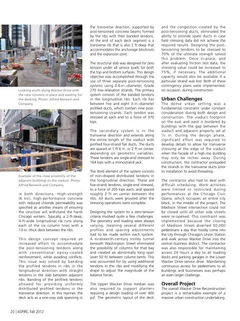
Looking south along Wacker Drive with<br />
the new columns in place and waiting for<br />
the decking. Photo: Alfred Benesch and<br />
Company.<br />
Example of the close proximity of the<br />
adjacent buildings to the viaduct. Photo:<br />
Alfred Benesch and Company.<br />
in both directions. High-strength<br />
(6 ksi), high-performance concrete<br />
with reduced chloride permeability was<br />
specified as another means of ensuring<br />
the structure will withstand the harsh<br />
Chicago winters. Typically, a 2-ft-deep,<br />
4-ft-wide longitudinal rib runs along<br />
each of the six column lines with a<br />
13-in.-thick deck between the ribs.<br />
This design concept required an<br />
increased effort to accommodate<br />
the post-tensioning tendons along<br />
with conventional epoxy-coated<br />
reinforcement, while avoiding conflicts.<br />
This issue was solved by banding<br />
the profiled tendons in ribs in the<br />
longitudinal direction with straight<br />
tendons in the slab between adjacent<br />
ribs. Banding of the profiled tendons<br />
allowed for providing uniformly<br />
distributed profiled tendons in the<br />
transverse direction. In this manner, the<br />
deck acts as a one-way slab spanning in<br />
the transverse direction, supported by<br />
post-tensioned concrete beams formed<br />
by the ribs with their banded tendons.<br />
At the end of each deck segment is a<br />
transverse rib that is also 2 ft deep that<br />
accommodates the anchorage blockouts<br />
and the expansion joint.<br />
<strong>The</strong> structural slab was designed for zero<br />
tension under all service loads for both<br />
the top and bottom surfaces. This design<br />
objective was accomplished through the<br />
use of three separate post-tensioning<br />
systems using 0.6-in.-diameter, Grade<br />
270 low-relaxation strands. <strong>The</strong> primary<br />
system consists of the banded tendons<br />
in the longitudinal ribs. Each rib has<br />
between five and eight 3-in.-diameter<br />
profiled ducts, which contain nine posttensioning<br />
strands. Each tendon was<br />
stressed at each end to a force of 370<br />
kips.<br />
<strong>The</strong> secondary system is in the<br />
transverse direction and extends along<br />
the entire length of the viaduct with<br />
profiled four-strand flat ducts. <strong>The</strong> ducts<br />
are spaced at 1 ft 6 in. or 2 ft on center,<br />
depending on geometric variables.<br />
<strong>The</strong>se tendons are single-end stressed to<br />
164 kips with a monostrand jack.<br />
<strong>The</strong> third element of the system consists<br />
of non-draped distributed tendons in<br />
the longitudinal direction. <strong>The</strong>se are<br />
five-strand tendons, single-end stressed,<br />
to a force of 205 kips each, and spaced<br />
roughly 2 ft on center between the<br />
ribs. All ducts were grouted after the<br />
stressing operations were complete.<br />
Designing the system to a zero-tension<br />
criteria involved quite a few challenges.<br />
<strong>The</strong> geometry and loading were always<br />
varying, meaning several different<br />
profiles and spacing adjustments<br />
had to be made within each system.<br />
A nineteenth-century trolley tunnel<br />
beneath Washington Street eliminated<br />
the possibility of columns for that bay<br />
and created an abnormally long span<br />
(over 50 ft) between column bents. This<br />
was accounted for by using additional<br />
tendons in the ribs and modifying the<br />
drape to adjust the magnitude of the<br />
balance forces.<br />
<strong>The</strong> Upper Wacker Drive median was<br />
also required to support planters<br />
requiring a design loading of over 400<br />
psf. <strong>The</strong> geometric layout of the deck<br />
and the congestion created by the<br />
post-tensioning ducts, eliminated the<br />
ability to provide spare ducts in case<br />
field stressing data did not achieve the<br />
required results. Designing the posttensioning<br />
tendons to be stressed to<br />
70% of the ultimate strength solved<br />
this problem. Once in-place, and<br />
after evaluating friction test data, the<br />
stressing value could be increased to<br />
75%, if necessary. <strong>The</strong> additional<br />
capacity would also be available if a<br />
particular strand was lost. Both of these<br />
contingency plans were implemented,<br />
on occasion, during construction.<br />
Urban Challenges<br />
<strong>The</strong> dense urban setting was a<br />
fundamental constraint under constant<br />
consideration during both design and<br />
construction. <strong>The</strong> viaduct footprint<br />
on the east and west is bordered by<br />
buildings with the gap between the<br />
viaduct and adjacent property set at<br />
7<br />
/ 8 in. During the design phase,<br />
significant effort was required to<br />
develop details to allow for transverse<br />
stressing at the edge of the viaduct<br />
when the facade of a high-rise building<br />
may only be inches away. During<br />
construction, the contractor preloaded<br />
the strands in the transverse ducts prior<br />
to installation to avoid threading.<br />
<strong>The</strong> contractor also had to deal with<br />
difficult scheduling. Work activities<br />
were limited or restricted during<br />
performances at the Chicago Civic<br />
Opera, which occupies an entire city<br />
block, in the middle of the project. <strong>The</strong><br />
Madison Street intersection could not<br />
be closed until all other side streets<br />
were re-opened. This constraint was<br />
implemented because the closing<br />
of Madison Street diverted 50,000<br />
pedestrians a day that mostly come into<br />
the city through Chicago’s Union Station<br />
and walk across Wacker Drive into the<br />
central business district. <strong>The</strong> contractor<br />
was also responsible for maintaining<br />
access 24 hours a day to all loading<br />
docks and parking garages in the Lower<br />
Wacker Drive service drive. Maintaining<br />
continuous access for pedestrians to all<br />
buildings and businesses was perhaps<br />
an even larger challenge.<br />
Overall Project<br />
<strong>The</strong> overall Wacker Drive Reconstruction<br />
project is a remarkable example of a<br />
massive urban construction undertaking.<br />
20 | <strong>ASPIRE</strong>, <strong>Fall</strong> <strong>2012</strong>


