RainMaster Evolution DX2 Controller Owners Manual - Irrigation Direct
RainMaster Evolution DX2 Controller Owners Manual - Irrigation Direct
RainMaster Evolution DX2 Controller Owners Manual - Irrigation Direct

You also want an ePaper? Increase the reach of your titles
YUMPU automatically turns print PDFs into web optimized ePapers that Google loves.
<strong>Evolution</strong> <strong>DX2</strong><br />
<strong>Evolution</strong> <strong>DX2</strong><br />
<strong>Evolution</strong> DX 2<br />
USER User MANUAL <strong>Manual</strong><br />
SUN or RAIN,<br />
We’re in Control
Rain Master <strong>Irrigation</strong> Systems<br />
<strong>DX2</strong> User <strong>Manual</strong><br />
Table Of Contents<br />
CHAPTER 1......................................................................................... 1<br />
INTRODUCTION ............................................................................... 1<br />
ABOUT THIS MANUAL....................................................................... 1<br />
FEATURES AND CAPABILITIES................................................... 4<br />
EVOLUTION <strong>DX2</strong> FEATURES AND SPECIFICATIONS............ 4<br />
HARDWARE FEATURES...................................................................... 4<br />
SCHEDULING CAPABILITIES............................................................... 5<br />
PROGRAM SETUP OPTIONS ................................................................ 6<br />
MAINTENANCE AND ALARM DIAGNOSTIC CAPABILITIES .................. 6<br />
MISCELLANEOUS FEATURES.............................................................. 8<br />
ELECTRICAL SPECIFICATIONS............................................................ 9<br />
CHAPTER 2......................................................................................... 9<br />
SYSTEM BASICS ............................................................................... 9<br />
EVOLUTION <strong>DX2</strong> CONTROLLER FRONT PANEL ................................. 9<br />
EVOLUTION <strong>DX2</strong> CONTROLLER FRONT PANEL ............................... 10<br />
BASE SCREEN .................................................................................. 12<br />
MAIN MENU .................................................................................... 14<br />
USING THE CONTROLLER KEYS....................................................... 15<br />
"Beep" Responses....................................................................... 17<br />
System Configuration................................................................. 17<br />
Keyboard Main Panel ................................................................ 17<br />
Main Power Switch Box............................................................. 18<br />
Master Valve/Pump/Power Board ............................................. 18<br />
Station Output Board ................................................................. 18<br />
Communication Board (optional) .............................................. 19<br />
Sensor Terminal Board (optional) ............................................. 19<br />
<strong>DX2</strong> Pedestal <strong>Controller</strong> Assembly Layout................................ 20<br />
CHAPTER 3....................................................................................... 23<br />
GETTING STARTED....................................................................... 23<br />
INITIALIZATION PROCEDURE ........................................................... 23<br />
MASTER VALVE/PUMP PROGRAM DEFAULT OPTIONS..................... 25<br />
TO CREATE A PROGRAM, THE FOLLOWING PARAMETERS MUST BE SET:<br />
........................................................................................................ 28<br />
CHAPTER 4....................................................................................... 35<br />
Table of Contents<br />
i
Rain Master <strong>Irrigation</strong> Systems<br />
<strong>DX2</strong> User <strong>Manual</strong><br />
SETUP ................................................................................................35<br />
SYSTEM DEFAULTS..........................................................................35<br />
SYSTEM DEFAULTS..........................................................................36<br />
PROGRAM ........................................................................................41<br />
Program Setup Procedure..........................................................42<br />
ISC (INDIVIDUAL STATION CONTROL).............................................50<br />
Station Number Procedure.........................................................51<br />
STATIONS.........................................................................................52<br />
STATIONS SETUP..............................................................................53<br />
Limits/Type Procedure ...............................................................55<br />
Main Flow Procedure ................................................................61<br />
Flow Max Main Line Limits .......................................................61<br />
Procedure...................................................................................62<br />
Auto Limits Procedure................................................................63<br />
SETUP CONTROLLER ........................................................................67<br />
Flow Options Procedure ............................................................68<br />
Omit By Date Procedure ............................................................72<br />
User Options Procedure.............................................................73<br />
Configuration Procedure ...........................................................79<br />
SENSORS ..........................................................................................83<br />
Moisture Procedure....................................................................83<br />
Flow Procedure..........................................................................84<br />
CHAPTER 5.......................................................................................89<br />
PROGRAM ENTRY .........................................................................89<br />
EXAMPLE OF PROGRAM EXECUTION................................................89<br />
EXAMPLE OF PROGRAM EXECUTION................................................90<br />
MODIFY PROGRAM ..........................................................................92<br />
Overview ....................................................................................92<br />
PROGRAM START TIME PROCEDURE................................................93<br />
Overview ....................................................................................93<br />
Procedure...................................................................................93<br />
WATERING DAY OPTIONS................................................................95<br />
Water Days Procedure (14 Day Cycle)......................................95<br />
Overview ....................................................................................95<br />
Procedure...................................................................................96<br />
WATER DAYS PROCEDURE (SKIP BY DAY)......................................98<br />
Overview ....................................................................................98<br />
Procedure...................................................................................98<br />
WATER DAYS PROCEDURE (31 DAY CYCLE).................................100<br />
Overview ..................................................................................100<br />
Procedure.................................................................................100<br />
ii<br />
Table of Contents
Rain Master <strong>Irrigation</strong> Systems<br />
<strong>DX2</strong> User <strong>Manual</strong><br />
STATIONS ...................................................................................... 102<br />
Overview .................................................................................. 102<br />
Procedure................................................................................. 102<br />
STATION RUN TIME OPTION .......................................................... 103<br />
Programming Individual Stations with Different Run Times ... 103<br />
Procedure................................................................................. 103<br />
QUICK STATION PROGRAMMING OPTION ...................................... 105<br />
Programming Station Groups with Identical Run Time........... 105<br />
Procedure................................................................................. 105<br />
PERCENT........................................................................................ 107<br />
Overview .................................................................................. 107<br />
Procedure................................................................................. 107<br />
SEND (APPLIES TO CENTRAL CONTROL SYSTEMS ONLY) .............. 109<br />
Overview .................................................................................. 109<br />
Procedure................................................................................. 109<br />
NEW PROGRAM ............................................................................. 111<br />
Overview .................................................................................. 111<br />
New Program Procedure ......................................................... 112<br />
REVIEW PROGRAM ........................................................................ 113<br />
Review Program Procedure..................................................... 114<br />
CLEAR PROGRAM .......................................................................... 116<br />
Clear Program Procedure ....................................................... 116<br />
PROGRAM ON/OFF......................................................................... 117<br />
PROGRAM ON/OFF PROCEDURE .................................................... 118<br />
Stopping a program ................................................................. 118<br />
Starting a Program .................................................................. 119<br />
CHAPTER 6..................................................................................... 120<br />
INDIVIDUAL STATION CONTROL........................................... 120<br />
ISC................................................................................................ 122<br />
CHAPTER 7..................................................................................... 123<br />
SYSTEM STATUS .......................................................................... 123<br />
COMM STATUS .............................................................................. 124<br />
MEASUREMENTS............................................................................ 125<br />
Measurements Procedure......................................................... 126<br />
WATER TOTAL .............................................................................. 129<br />
Water Total Procedure............................................................. 129<br />
REVIEW ALL.................................................................................. 131<br />
Procedure................................................................................. 131<br />
CHAPTER 8..................................................................................... 133<br />
Table of Contents<br />
iii
Rain Master <strong>Irrigation</strong> Systems<br />
<strong>DX2</strong> User <strong>Manual</strong><br />
MANUAL SYSTEM CONTROL...................................................133<br />
TEST ..............................................................................................134<br />
Procedure.................................................................................134<br />
MULTI-STATION ............................................................................137<br />
Procedure.................................................................................137<br />
MULTI-STATION DIAGNOSTICS......................................................142<br />
Diagnostic Procedure...............................................................142<br />
PRESS THE QUIT KEY TO RETURN TO THE BASE MENU...................145<br />
STATION ........................................................................................145<br />
Procedure.................................................................................145<br />
RAIN OFF .......................................................................................149<br />
Procedure.................................................................................149<br />
CHAPTER 9.....................................................................................153<br />
CENTRAL CONTROL...................................................................153<br />
CONTROLLER AS SUBMASTER........................................................154<br />
TRANSFERRING PROGRAMS BETWEEN THE CENTRAL CONTROL<br />
COMPUTER AND SUBMASTER/SATELLITE CONTROLLERS ..............155<br />
Upload Procedure ....................................................................155<br />
COMMUNICATIONS AND PROBLEM REPORTING .............................157<br />
Submaster.................................................................................157<br />
Satellite.....................................................................................157<br />
Diagnostics...............................................................................158<br />
<strong>Controller</strong> Logs ........................................................................158<br />
Weather Center Sensors ...........................................................159<br />
CHAPTER 10...................................................................................161<br />
FIELD MAINTENANCE ACTIVITY AND<br />
TROUBLESHOOTING ..................................................................161<br />
FLOW MONITORING........................................................................161<br />
BROKEN FIELD WIRING, SHORT CIRCUITS, AND FAULTY VALVE<br />
SOLENOIDS:....................................................................................161<br />
AC POWER INPUT PROBLEMS:........................................................161<br />
COMMUNICATIONS WIRING ISSUES: ...............................................161<br />
WARNING REPORT (ALARMS)........................................................163<br />
VIEWING THE WARNING LIST ........................................................164<br />
WARNING DISPLAY LIST................................................................165<br />
Standard Warnings...................................................................165<br />
Flow Max Warnings .................................................................166<br />
STANDARD FLOW WARNINGS........................................................167<br />
001 - Station Flow Too Low .....................................................167<br />
iv<br />
Table of Contents
Rain Master <strong>Irrigation</strong> Systems<br />
<strong>DX2</strong> User <strong>Manual</strong><br />
002 - Station Flow Too High.................................................... 169<br />
003 - Monthly Water Limit Violation ....................................... 171<br />
004 - Station Electrical Current Too High............................... 173<br />
005 - Station Electrical Current Too Low................................ 175<br />
006 - <strong>Controller</strong> Main Line Break Occurred ........................... 177<br />
007 - Hourly Rain Limit Was Exceeded ................................... 178<br />
008 - Hardwire Communications Restored (On Line) ............. 179<br />
009 - Off Line........................................................................... 180<br />
010 - Hardwire Communication Failure ................................. 182<br />
011 - Wind Lower Limit Satisfied............................................. 184<br />
012 - Wind Upper Limit Exceeded ........................................... 185<br />
013 - Power Failure................................................................. 186<br />
014 - Power Restoration .......................................................... 187<br />
015 - Program Upload Request ............................................... 188<br />
016 - Unscheduled Flow .......................................................... 189<br />
017 - Daily Rain Limit Reached............................................... 190<br />
018 - Short Circuit ................................................................... 191<br />
FLOW MAX WARNINGS ................................................................. 192<br />
019 - Flow Max - Flow Lower Limit Violation ........................ 192<br />
020 - Flow Max - Flow Upper Limit Violation ........................ 194<br />
021 - FM - Multiple Flow Sensor 1 Assignment ...................... 195<br />
022 - FM - Multiple Flow Sensor 2 Assignment ...................... 196<br />
023 - FM - Multiple Pump Assignment .................................... 197<br />
024 - FM - Multiple Master Valve ........................................... 199<br />
025 - FM - Multiple Master Valve 2 Assignment ..................... 200<br />
026 - FM - Multiple Normally Open Master Valves ................ 202<br />
027 - Flow Max - Station Advance........................................... 204<br />
028 - Flow Max - Stop Water................................................... 205<br />
029 - Auto Limits Aborted........................................................ 206<br />
030 - FM - Communications Failure ....................................... 207<br />
031- FM - Communications Restored ...................................... 209<br />
032 - Flow Max - Main Flow ................................................... 209<br />
032 - Flow Max - Main Flow ................................................... 210<br />
TROUBLESHOOTING....................................................................... 211<br />
<strong>Direct</strong>ory of Flow Chart Diagnostic Problems........................ 212<br />
Automatic Program Does Not Start ......................................... 213<br />
Flow Sensor Reading Always Zero .......................................... 215<br />
A Station/Valve Does Not Water .............................................. 218<br />
A Station/Valve Does Not Water .............................................. 218<br />
Display is Blank ....................................................................... 218<br />
Display is Blank ....................................................................... 219<br />
Display is Blank ....................................................................... 220<br />
Display is Blank ....................................................................... 221<br />
Table of Contents<br />
v
Rain Master <strong>Irrigation</strong> Systems<br />
<strong>DX2</strong> User <strong>Manual</strong><br />
<strong>Controller</strong> Emits a Constant Tone............................................223<br />
Program Starts - But Does Not Water......................................224<br />
Monthly Flow Violation Occurred but Program Still Operates<br />
..................................................................................................226<br />
Monthly Flow Violation Occurred but Program Still Operates<br />
..................................................................................................227<br />
Multiple Stations Do Not Water ...............................................228<br />
CONTROLLER STATION OUTPUT BOARD........................................229<br />
CONTROL DEVICES (RAIN SENSORS, FREEZE SENSORS, ETC.) .......231<br />
APPENDIX A...................................................................................232<br />
FLOW METERS .............................................................................232<br />
FLOW METER OPERATION OVERVIEW ...........................................233<br />
FLOW READING ACCURACY ..........................................................234<br />
FLOW METER OFFSET AND K VALUES...........................................234<br />
RAIN MASTER FLOW SENSORS..............................................235<br />
SELECTION CHART...................................................................235<br />
DATA INDUSTRIAL TEE MOUNTED SENSORS .................................236<br />
FLOW LIMIT CHECKING .................................................................236<br />
STATION UPPER LIMIT ...................................................................236<br />
STATION LOWER LIMIT..................................................................237<br />
MAIN FLOW LIMITS .......................................................................237<br />
TOTAL MONTHLY FLOW LIMIT......................................................238<br />
UNSCHEDULED FLOW LIMIT ..........................................................238<br />
ENABLING AND DISABLING FLOW LIMIT CHECKING......................239<br />
DELAYING FLOW RATE LIMIT CHECKING......................................239<br />
LIMIT CHECKING WITH TWO FLOW METERS..................................241<br />
FLOW METER READING .................................................................241<br />
Procedure.................................................................................241<br />
READING MONTHLY WATER TOTALS ............................................243<br />
Procedure.................................................................................243<br />
WHEN A FLOW LIMIT VIOLATION IS DETECTED.............................244<br />
FLOW LIMIT VIOLATION EXAMPLES ..............................................245<br />
Overflow in <strong>Controller</strong>/Main Line Break .................................245<br />
STATION OVERFLOW .....................................................................246<br />
STATION UNDER FLOW..................................................................246<br />
MONTHLY WATER LIMIT EXCEEDED.............................................246<br />
MULTIPLE STATIONS WITH NON-OVERLAP PROTECTION...............247<br />
APPENDIX B ...................................................................................254<br />
CURRENT MONITOR...................................................................254<br />
CURRENT MONITOR SETUP............................................................254<br />
vi<br />
Table of Contents
Rain Master <strong>Irrigation</strong> Systems<br />
<strong>DX2</strong> User <strong>Manual</strong><br />
CURRENT LIMIT DETECTION.......................................................... 255<br />
AUTO LIMITS PROCEDURE............................................................. 256<br />
ENABLING AND DISABLING CURRENT CHECKING ......................... 258<br />
Procedure................................................................................. 258<br />
STATION CURRENT LIMIT SETUP ................................................... 259<br />
Current Limit Setup Procedure:............................................... 260<br />
EXAMPLE CURRENT LIMIT VIOLATIONS........................................ 262<br />
Station Consumes Too Much Current ...................................... 262<br />
STATION CONSUMES TOO LITTLE CURRENT.................................. 262<br />
MULTIPLE STATIONS WITH NON-OVERLAP PROTECTION .............. 262<br />
MAXIMUM CONTROLLER CURRENT............................................... 263<br />
APPENDIX C................................................................................... 265<br />
POWER FAILURE/RECOVERY ................................................. 265<br />
PROBLEM REPORTING.................................................................... 265<br />
CANCELING AND CONTINUING WATERING PROGRAMS ................. 266<br />
APPENDIX D................................................................................... 269<br />
ACCESS CODES............................................................................. 269<br />
ENTERING AN ACCESS CODE ......................................................... 269<br />
Procedure: ............................................................................... 269<br />
USING ACCESS CODES................................................................... 272<br />
Gain Access Procedure:........................................................... 273<br />
APPENDIX E................................................................................... 275<br />
FLOW MAX .................................................................................... 275<br />
OVERVIEW..................................................................................... 276<br />
SUBMASTER................................................................................... 277<br />
DEVICES ........................................................................................ 277<br />
FLOW SENSORS.............................................................................. 278<br />
FLOW CHECK DELAY..................................................................... 279<br />
MAIN LINE LIMITS......................................................................... 279<br />
FLOW MAX LIMITATIONS .............................................................. 279<br />
PHYSICAL CONFIGURATION........................................................... 280<br />
FLOW MAX SETUP PROCEDURE..................................................... 285<br />
Overview .................................................................................. 285<br />
Submaster: ..................................................................................... 285<br />
Satellite: ......................................................................................... 285<br />
SUBMASTER SETUP PROCEDURE.................................................... 286<br />
FLOW MAX MAIN LINE FLOW LIMITS PROCEDURE ....................... 292<br />
MAIN FLOW PROCEDURE............................................................... 292<br />
Table of Contents<br />
vii
Rain Master <strong>Irrigation</strong> Systems<br />
<strong>DX2</strong> User <strong>Manual</strong><br />
SATELLITE CONTROLLERS .............................................................294<br />
Procedure.................................................................................294<br />
FLOW MAX WORKSHEET ...............................................................301<br />
FLOW MAX DIAGNOSTIC TOOLS....................................................304<br />
Real Time Flow Monitor ..........................................................304<br />
Procedure.................................................................................304<br />
PRESS THE QUIT KEY TO RETURN TO THE BASE MENU...................306<br />
REVIEW FLOW MAX PHYSICAL CONFIGURATION ..........................306<br />
Review All Procedure...............................................................306<br />
FLOW MAX WARNINGS AND EXCEPTION CONDITIONS ..................309<br />
FLOW MAX LOWER LIMIT VIOLATION...........................................309<br />
FLOW MAX UPPER LIMIT VIOLATION............................................310<br />
FLOW MAX COMMUNICATIONS FAILURE.......................................311<br />
FLOW MAX MAIN FLOW................................................................312<br />
FLOW MAX UNSCHEDULED FLOW .................................................312<br />
APPENDIX F ...................................................................................314<br />
TROUBLESHOOTING BASICS...................................................314<br />
ANALOG MULTIMETERS ................................................................315<br />
VOLTAGE SCALE............................................................................316<br />
DIGITAL MULTIMETERS.................................................................317<br />
TROUBLESHOOTING .......................................................................318<br />
CABLE CHECKOUT PROCEDURE.....................................................318<br />
POLARITY CHECKOUT PROCEDURE................................................321<br />
REQUIRED EQUIPMENT ..................................................................321<br />
Procedure.................................................................................321<br />
ALTERNATE POLARITY CHECKOUT PROCEDURE............................324<br />
REQUIRED EQUIPMENT ..................................................................324<br />
Procedure.................................................................................324<br />
GLOSSARY .....................................................................................328<br />
INDEX ..............................................................................................338<br />
RAIN MASTER LIMITED WARRANTY....................................355<br />
Table of Figures<br />
FIGURE 1: EVOLUTION <strong>DX2</strong> PEDESTAL ENCLOSURE..........2<br />
FIGURE 2: EVOLUTION <strong>DX2</strong> CONTROLLER FACE PANEL 10<br />
FIGURE 3: BASE SCREEN .............................................................12<br />
FIGURE 4: MAIN MENU ................................................................14<br />
viii<br />
Table of Contents
Rain Master <strong>Irrigation</strong> Systems<br />
<strong>DX2</strong> User <strong>Manual</strong><br />
FIGURE 5: PEDESTAL CONTROLLER ASSEMBLY LAYOUT<br />
............................................................................................................. 20<br />
FIGURE 6: AC POWER SUPPLY WIRING DIAGRAM ............ 21<br />
FIGURE 7: MASTER VALVE AND STATION CONNECTION 22<br />
FIGURE 8: LANGUAGE SELECTION ......................................... 23<br />
FIGURE 9: YEAR ENTRY .............................................................. 24<br />
FIGURE 10: MONTH ENTRY........................................................ 24<br />
FIGURE 11: DAY OF THE MONTH ENTRY .............................. 24<br />
FIGURE 12: DAY OF THE WEEK ENTRY.................................. 25<br />
FIGURE 13: TIME OF DAY ENTRY............................................. 25<br />
FIGURE 14: MASTER VALVE OPTIONS.................................... 26<br />
FIGURE 15: PUMP OPTIONS........................................................ 26<br />
FIGURE 16: BASE SCREEN DISPLAY ........................................ 26<br />
FIGURE 17: PROGRAM ENTRY .................................................. 42<br />
FIGURE 18: CYCLE MODE........................................................... 43<br />
FIGURE 19: OVERLAP PROTECTION ....................................... 43<br />
FIGURE 20: IRRIGATION PROGRAM ....................................... 44<br />
FIGURE 21: OMIT BY DATE OPTION ........................................ 45<br />
FIGURE 22: STATION DELAY TIME DISPLAY........................ 45<br />
FIGURE 23: TIME FORMAT......................................................... 46<br />
FIGURE 24: AT WATER LIMIT.................................................... 47<br />
FIGURE 25: MASTER VALVE SELECTION .............................. 47<br />
FIGURE 26: PUMP SELECTION................................................... 48<br />
FIGURE 27: VALVE ON/OFF BETWEEN STATIONS .............. 48<br />
FIGURE 28: VALVE DELAY TURN ON TIME........................... 49<br />
FIGURE 29: ISC PROGRAM NUMBER ....................................... 51<br />
FIGURE 30: STATION LIMITS OPTIONS .................................. 53<br />
FIGURE 31: FLOW/CURRENT SELECTION ............................. 53<br />
FIGURE 32: UPPER LIMIT CHECK ............................................ 54<br />
FIGURE 33: LOWER LIMIT CHECK .......................................... 54<br />
FIGURE 34: LIMITS/TYPE ............................................................ 56<br />
FIGURE 35: LIMIT OPTIONS ....................................................... 57<br />
FIGURE 36: MAX CURRENT LIMIT........................................... 57<br />
FIGURE 37: MIN CURRENT LIMIT ............................................ 58<br />
FIGURE 38: MAX FLOW LIMIT................................................... 58<br />
FIGURE 39: MIN FLOW LIMIT.................................................... 58<br />
FIGURE 40: STATION TYPE......................................................... 59<br />
FIGURE 41: MAIN FLOW LIMIT ENTRY .................................. 62<br />
FIGURE 42: MAIN LIMIT OPTIONS ........................................... 62<br />
FIGURE 43: MAIN FLOW MAXIMUM LIMIT........................... 62<br />
FIGURE 44: AUTO LIMITS ........................................................... 63<br />
FIGURE 45: AUTO LIMITS ........................................................... 64<br />
FIGURE 46: AUTO LIMITS ........................................................... 65<br />
Table of Contents<br />
ix
Rain Master <strong>Irrigation</strong> Systems<br />
<strong>DX2</strong> User <strong>Manual</strong><br />
FIGURE 47: CONTROLLER OPTIONS .......................................68<br />
FIGURE 48: LIMIT OPTIONS........................................................68<br />
FIGURE 49: MONTHLY WATER LIMIT ....................................69<br />
FIGURE 50: FLOW METER SELECTION...................................70<br />
FIGURE 51: DELAY LIMIT TIME................................................71<br />
FIGURE 52: UNSCHED FLOW LIMIT.........................................71<br />
FIGURE 53: OMISSION DATES....................................................72<br />
FIGURE 54: MONTH ENTRY ........................................................72<br />
FIGURE 55: DAY OF THE MONTH..............................................73<br />
FIGURE 56: USER OPTIONS .........................................................73<br />
FIGURE 57: TIME FORMAT .........................................................74<br />
FIGURE 58: TIME ENTRY FORMAT ..........................................74<br />
FIGURE 59: YEAR ENTRY FORMAT..........................................75<br />
FIGURE 60: MONTH ENTRY FORMAT......................................75<br />
FIGURE 61: DATE OF THE MONTH ENTRY ............................75<br />
FIGURE 62: DATE FORMAT OPTIONS......................................75<br />
FIGURE 63: DATE FORMAT OPTIONS......................................76<br />
FIGURE 64: DAY OF WEEK ENTRY FORMAT.........................76<br />
FIGURE 65: USER OPTIONS .........................................................76<br />
FIGURE 66: ACCESS CODE ..........................................................77<br />
FIGURE 67: ACCESS CODE ..........................................................78<br />
FIGURE 68: ACCESS RESTRICTION ..........................................78<br />
FIGURE 69: SELECT ACCESS LEVEL........................................79<br />
FIGURE 70: SELECT ACCESS LEVEL........................................79<br />
FIGURE 71: CONFIGURATION OPTIONS .................................80<br />
FIGURE 72: SUBMASTER COMMUNICATION ........................81<br />
FIGURE 73: SUBMASTER ADDRESS ..........................................81<br />
FIGURE 74: SHARED DEVICES ...................................................82<br />
FIGURE 75: SENSOR OPTIONS....................................................83<br />
FIGURE 76: SENSORS SETUP.......................................................83<br />
FIGURE 77: SENSOR OPTIONS....................................................84<br />
FIGURE 78: FLOW METER SELECTION...................................84<br />
FIGURE 79: K VALUE ENTRY......................................................85<br />
FIGURE 80: OFFSET VALUE ENTRY .........................................85<br />
FIGURE 81: PROGRAM 1...............................................................91<br />
FIGURE 82: MODIFY PROGRAM ................................................92<br />
FIGURE 83: START TIME ENTRY...............................................93<br />
FIGURE 84: WATER DAYS OPTIONS.........................................96<br />
FIGURE 85: WEEK 1 ENTRY ........................................................96<br />
FIGURE 86: SKIP BY DAY ENTRY ..............................................98<br />
FIGURE 87: START WATER DAY................................................99<br />
FIGURE 88: 31 DAYS CYCLE ENTRY.......................................100<br />
FIGURE 89: STATIONS ................................................................102<br />
x<br />
Table of Contents
Rain Master <strong>Irrigation</strong> Systems<br />
<strong>DX2</strong> User <strong>Manual</strong><br />
FIGURE 90: STATION RUN TIME OPTIONS .......................... 103<br />
FIGURE 91: SELECT STATION NUMBER ............................... 104<br />
FIGURE 92: STATION RUN TIME ENTRY .............................. 104<br />
FIGURE 93: QUICK STATION NUMBER ENTRY .................. 105<br />
FIGURE 94: QUICK STATION TOTAL RUNTIME................. 106<br />
FIGURE 95: PERCENTAGE RUN TIME ................................... 107<br />
FIGURE 96: MODIFY PROGRAM.............................................. 109<br />
FIGURE 97: PROGRAM UPLOAD REQUEST.......................... 109<br />
FIGURE 98: WATER DAY CYCLE OPTIONS.......................... 112<br />
FIGURE 99: PROGRAM ENTRY ................................................ 114<br />
FIGURE 100: WEEK 1 WATER DAYS ....................................... 114<br />
FIGURE 101: PROGRAM CLEAR NUMBER............................ 116<br />
FIGURE 102: ISC............................................................................ 122<br />
FIGURE 103: SYSTEM STATUS OPTIONS............................... 123<br />
FIGURE 104: COMM STATUS .................................................... 124<br />
FIGURE 105: MEASUREMENTS OPTION................................ 126<br />
FIGURE 106: FLOW METER MEASUREMENTS.................... 126<br />
FIGURE 107: CURRENT METER MEASUREMENTS ............ 127<br />
FIGURE 108: ET............................................................................. 127<br />
FIGURE 109: RAIN/WIND READINGS...................................... 128<br />
FIGURE 110: WATER TOTALS .................................................. 129<br />
FIGURE 111: PAST MONTH WATER TOTALS....................... 130<br />
FIGURE 112: REVIEW WATER DAYS...................................... 131<br />
FIGURE 113: MANUAL MAIN MENU ....................................... 133<br />
FIGURE 114: OPERATION TIME............................................... 134<br />
FIGURE 115: PROGRAM TESTING........................................... 135<br />
FIGURE 116: MULTI-STATION OPTIONS............................... 137<br />
FIGURE 117: STATION ON SEQUENTIALLY......................... 139<br />
FIGURE 118: STATION RUN TIME ........................................... 140<br />
FIGURE 119: START LATER TIME........................................... 141<br />
FIGURE 120: WARNING, SHORT CIRCUIT ............................ 142<br />
FIGURE 121: MULTI-STATION OPTIONS............................... 143<br />
FIGURE 122: RUN TIME ENTRY ............................................... 143<br />
FIGURE 123: STATION/DEVICE ENTRY................................. 143<br />
FIGURE 124: STATION/DEVICE ENTRY................................. 144<br />
FIGURE 125: STATION NUMBER ENTRY............................... 145<br />
FIGURE 126: STATION OPTIONS.............................................. 146<br />
FIGURE 127: RUN TIME ENTRY ............................................... 146<br />
FIGURE 128: STATION RUN STATUS ...................................... 147<br />
FIGURE 129: MANUAL OPERATIONS MENU ........................ 148<br />
FIGURE 130: RAIN OFF ............................................................... 149<br />
FIGURE 131: RAIN SHUTDOWN................................................ 150<br />
FIGURE 132: NO WATER WINDOW TIME ............................. 151<br />
Table of Contents<br />
xi
Rain Master <strong>Irrigation</strong> Systems<br />
<strong>DX2</strong> User <strong>Manual</strong><br />
FIGURE 133: PROGRAMMABLE RAIN SHUTDOWN ...........151<br />
FIGURE 134: SATELLITE ADDRESS DISPLAY ......................154<br />
FIGURE 135: MODIFY PROGRAM ............................................155<br />
FIGURE 136: PROGRAM SEND..................................................156<br />
FIGURE 137: WARNING REPORT.............................................157<br />
FIGURE 138: PROBLEM OFF-LINE...........................................157<br />
FIGURE 139: PROBLEM ON-LINE.............................................158<br />
FIGURE 140: WEATHER CENTER CONNECTIONS..............160<br />
FIGURE 141: BASE SCREEN .......................................................164<br />
FIGURE 142: WARNING 001 -FLOW LOWER LIMIT............167<br />
FIGURE 143: WARNING 002-FLOW UPPER LIMIT...............169<br />
FIGURE 144: WARNING 003-WATER LIMIT ..........................171<br />
FIGURE 145: WARNING 004-CURRENT UPPER LIMIT .......173<br />
FIGURE 146: WARNING 005-CURRENT LOW LIMIT...........175<br />
FIGURE 147: WARNING 006-MAIN FLOW ..............................177<br />
FIGURE 148: WARNING 007-HOURLY RAIN LIMIT.............178<br />
FIGURE 149: WARNING 008-ON LINE......................................179<br />
FIGURE 150: WARNING 009-OFF LINE....................................180<br />
FIGURE 151: WARNING 010-HARDWIRE COMMUNICATION<br />
FAILURE .........................................................................................182<br />
FIGURE 152: WARNING 011-WIND LOWER LIMIT..............184<br />
FIGURE 153: WARNING 012-WIND UPPER LIMIT................185<br />
FIGURE 154: WARNING 013-POWER FAILURE ....................186<br />
FIGURE 155: WARNING 014-POWER ON ................................187<br />
FIGURE 156: WARNING 015-UPLOAD REQUEST..................188<br />
FIGURE 157: WARNING 016-UNSCHEDULED LIMIT...........189<br />
FIGURE 158: WARNING 017-DAILY RAIN LIMIT .................190<br />
FIGURE 159: WARNING 018-SHORT CIRCUIT ......................191<br />
FIGURE 160: WARNING 019-FM FLOW LOW LIMIT ...........192<br />
FIGURE 161: WARNING 020-FM FLOW UPPER LIMIT........194<br />
FIGURE 162: WARNING 021-FM MULTIPLE FLOW METER 1<br />
ASSIGN ............................................................................................195<br />
FIGURE 163: WARNING 022-FM MULTIPLE FLOW METER 2<br />
ASSIGN ............................................................................................196<br />
FIGURE 164: WARNING 023-FM MULTIPLE PUMP .............197<br />
FIGURE 165: WARNING 024-FM MULTIPLE MV1<br />
ASSIGNMENT.................................................................................199<br />
FIGURE 166: WARNING 025-FM MULTIPLE MV2<br />
ASSIGNMENT.................................................................................200<br />
FIGURE 167: WARNING 026 -FM MULTIPLE N.O.<br />
ASSIGNMENT.................................................................................202<br />
FIGURE 168: WARNING 027-FM STATION ADVANCE ........204<br />
FIGURE 169: WARNING 028 -FM STOP WATER....................205<br />
xii<br />
Table of Contents
Rain Master <strong>Irrigation</strong> Systems<br />
<strong>DX2</strong> User <strong>Manual</strong><br />
FIGURE 170: WARNING 029 -AUTO LIMITS .......................... 206<br />
FIGURE 171: WARNING 030 -FM HARDWIRE COMM<br />
FAILURE ......................................................................................... 207<br />
FIGURE 172: WARNING 031 -FM COMMUNICATIONS<br />
RESTORED ..................................................................................... 209<br />
FIGURE 173: WARNING 032 -FM MAIN FLOW...................... 210<br />
FIGURE 174: OUTPUT BOARD STATION CONNECTIONS. 229<br />
FIGURE 175: MEASUREMENT OPTIONS................................ 241<br />
FIGURE 176: FLOW METER READINGS................................. 242<br />
FIGURE 177: STATUS OPTIONS................................................ 243<br />
FIGURE 178: WATER TOTAL .................................................... 243<br />
FIGURE 179: WARNING, MAIN FLOW .................................... 245<br />
FIGURE 180: WARNING, UNSCHED LIMIT............................ 245<br />
FIGURE 181: WARNING, FLOW UP LIMIT............................. 246<br />
FIGURE 182: WARNING, FLOW LOW LIMIT ........................ 246<br />
FIGURE 183: WARNING, WATER LIMIT ................................ 246<br />
FIGURE 184: FLOW SENSOR INSTALLATION...................... 253<br />
FIGURE 185: AUTO LIMITS ....................................................... 256<br />
FIGURE 186: AUTO LIMITS ....................................................... 257<br />
FIGURE 187: AUTO LIMITS ....................................................... 258<br />
FIGURE 188: CURRENT LIMIT OPTIONS............................... 259<br />
FIGURE 189: UPPER LIMIT ENABLE OPTION...................... 259<br />
FIGURE 190: LIMIT OPTIONS ................................................... 260<br />
FIGURE 191: CURRENT LIMIT ENTRY................................... 261<br />
FIGURE 192: WARNING, UP LIMIT.......................................... 262<br />
FIGURE 193: WARNING, LOW LIMIT ..................................... 262<br />
FIGURE 194: SHORT CIRCUIT WARNING ............................. 263<br />
FIGURE 195: FUSE DISPLAY MESSAGE ................................. 263<br />
FIGURE 196: ACCESS CODE ...................................................... 269<br />
FIGURE 197: ACCESS CODE OPTIONS ................................... 270<br />
FIGURE 198: ACCESS RESTRICTION STATUS ..................... 270<br />
FIGURE 199: LEVEL ACCESS SELECTION............................ 271<br />
FIGURE 200: ACCESS DENIED DISPLAY................................ 273<br />
FIGURE 201: ACCESS CODE ...................................................... 273<br />
FIGURE 202: ACCESS CODE OPTIONS ................................... 274<br />
FIGURE 203: ACCESS RESTRICTION STATUS ..................... 274<br />
FIGURE 204: FLOW MAX HARDWIRE CONFIGURATION 281<br />
FIGURE 205: DETAILED HARDWIRE CONNECTIONS ....... 282<br />
FIGURE 206: DETAILED MASTER VALVE AND STATION<br />
CONNECTIONS ............................................................................. 283<br />
FIGURE 207: SUBMASTER ADDRESS ENTRY ....................... 286<br />
FIGURE 208: MASTER VALVE/PUMP SELECTION.............. 287<br />
FIGURE 209: FLOW METER 1 CONNECTION ....................... 287<br />
Table of Contents<br />
xiii
Rain Master <strong>Irrigation</strong> Systems<br />
<strong>DX2</strong> User <strong>Manual</strong><br />
FIGURE 210: PUMP CONNECTION...........................................288<br />
FIGURE 211: MASTER VALVE 1 CONNECTION ...................288<br />
FIGURE 212: MASTER VALVE 2 CONNECTION ...................289<br />
FIGURE 213: NORMALLY OPEN VALVE CONNECTION....289<br />
FIGURE 214: LAST ADDRESS ENTRY......................................290<br />
FIGURE 215: FLOW METER SELECTION...............................290<br />
FIGURE 216: K VALUE ENTRY..................................................291<br />
FIGURE 217: OFFSET VALUE ENTRY .....................................291<br />
FIGURE 218: MAIN FLOW LIMIT ENTRY ..............................292<br />
FIGURE 219: MAIN LIMIT OPTIONS........................................293<br />
FIGURE 220: MAIN FLOW MAXIMUM LIMIT.......................293<br />
FIGURE 221: UNSCHED FLOW LIMIT.....................................294<br />
FIGURE 222: NORMAL MODE ...................................................295<br />
FIGURE 223: CONTROLLER OPTIONS ...................................295<br />
FIGURE 224: FLOW METER CONNECTION...........................296<br />
FIGURE 225: FLOW METER CONNECTION...........................297<br />
FIGURE 226: MASTER VALVE CONNECTION ......................298<br />
FIGURE 227: AUTO LIMITS........................................................300<br />
FIGURE 228: CONFIGURATION BLOCK DIAGRAM............303<br />
FIGURE 229: SUBMASTER REAL TIME REVIEW.................304<br />
FIGURE 230: SATELLITE REAL TIME REVIEW...................306<br />
FIGURE 231: PROGRAM PARAMETERS.................................306<br />
FIGURE 232: SUBMASTER CONFIGURATION ......................307<br />
FIGURE 233: SATELLITE 001 CONFIGURATION .................307<br />
FIGURE 234: SATELLITE 002 CONFIGURATION .................307<br />
FIGURE 235: ANALOG MULTIMETER ....................................315<br />
FIGURE 236: CABLE CONTINUITY CHECK...........................320<br />
FIGURE 237: POLARITY CHECK ..............................................323<br />
FIGURE 238: +8 VOLT POLARITY CHECK.............................326<br />
Table of Tables<br />
TABLE 1: SETUP OPTIONS AND SYSTEM DEFAULTS..........36<br />
TABLE 2: PROGRAM 1 WATERING SCHEDULE ....................90<br />
TABLE 3: CALIBRATION TABLE..............................................235<br />
TABLE 4: RAIN MASTER K AND OFFSET VALUE ...............248<br />
TABLE 5: ACCESS LEVEL OPTIONS........................................272<br />
TABLE 6: FLOW MAX SAMPLE WORKSHEET .....................301<br />
xiv<br />
Table of Contents
Rain Master <strong>Irrigation</strong> Systems<br />
<strong>DX2</strong> User <strong>Manual</strong><br />
Chapter 1<br />
Introduction<br />
Congratulations… You have just acquired the worlds most<br />
advanced, trouble free, solid state irrigation controller.<br />
Rain Master is pleased to offer the first irrigation controller with<br />
expandable capabilities that can grow your needs become more<br />
complex and demanding.<br />
As you become acquainted with the <strong>Evolution</strong> <strong>DX2</strong>'s total<br />
capabilities, you will realize how simple it is to program and<br />
operate.<br />
Thank you for choosing Rain Master <strong>Irrigation</strong> Systems.<br />
About This <strong>Manual</strong><br />
This manual is designed to serve as a User <strong>Manual</strong>, Reference<br />
Source, and Maintenance Guide. The procedures are presented<br />
in systematic steps to easily complete a specific task. The menus<br />
throughout these chapters are identified with a sequential listing<br />
that starts out with a pointing finger icon (as shown below). This<br />
presentation is intended to quickly indicate the menus in the<br />
proper order to arrive at the correct programming display screen.<br />
F1=Main Menu<br />
F2=Program<br />
F3=New Program<br />
Chapter 1:<br />
Introduction<br />
Chapter 1: Introduction Page 1
Rain Master <strong>Irrigation</strong> Systems<br />
<strong>DX2</strong> User <strong>Manual</strong><br />
Figure 1: <strong>Evolution</strong> <strong>DX2</strong> Pedestal Enclosure<br />
Page 2<br />
Chapter 1: Introduction
Rain Master <strong>Irrigation</strong> Systems<br />
<strong>DX2</strong> User <strong>Manual</strong><br />
Every attempt has been made to show the appropriate screen<br />
display throughout the step-by-step process. In cases where a<br />
sub-menu is not shown, refer back to the preceding pointing<br />
finger icon. Following the listing from that point will easily<br />
direct you to the correct sub-menu.<br />
The <strong>Evolution</strong> <strong>DX2</strong> <strong>Controller</strong> was designed to accommodate a<br />
wide range of features and capabilities with unequaled versatility<br />
and performance. At the same time, it remains extremely simple<br />
to use.<br />
In addition to being the detailed definitive source for all facets of<br />
the controller operation, this manual contains extensive<br />
troubleshooting information required to resolve field<br />
maintenance issues.<br />
Some features of this manual are highlighted below:<br />
Chapter 2: System Basics introduces you to the irrigation<br />
controller’s front panel by defining basic key<br />
operations.<br />
Chapter 3: Getting Started is designed as a quick reference<br />
guide. This chapter allows you to initialize a<br />
controller and enter a new program in less than 5<br />
minutes.<br />
Chapter 10: Troubleshooting includes field troubleshooting<br />
flow charts as well as detailed alarm warning<br />
information. Specific appendices have been<br />
provided with emphasis on troubleshooting<br />
techniques as they relate to the irrigation controller.<br />
Appendix G: Troubleshooting Basics addresses basic<br />
troubleshooting principles including an introduction<br />
to volt/ohm meter concepts.<br />
Chapter 1: Introduction Page 3
Rain Master <strong>Irrigation</strong> Systems<br />
<strong>DX2</strong> User <strong>Manual</strong><br />
Features and Capabilities<br />
Microprocessor-based control of irrigation systems is no longer a<br />
luxury. Today’s culture is environmentally sensitive, exact<br />
control of precious water resources is a must. Even with low<br />
precipitation irrigation, excessive run times mean wasted water.<br />
Rain Master believes in minimizing waste by maximizing water<br />
application efficiency.<br />
The <strong>Evolution</strong> <strong>DX2</strong> is designed to provide precise control of<br />
irrigation delivery systems. The water savings realized from<br />
these control efficiencies will help ensure an adequate supply of<br />
clean water for personal needs, as well as for landscapes, which<br />
are so important to the quality of our lives.<br />
<strong>Evolution</strong> <strong>DX2</strong> Features and Specifications<br />
Hardware Features<br />
• Configuration options 6, 12, 18, 24, 30, 36, 42 or 48<br />
stations. Dedicated outputs for 2 Normally Closed<br />
Master Valves, 1 normally Open Master Valve, 1 Pump,<br />
and auxiliary 24 VAC.<br />
• Connectivity for 4 input sensing devices. 4 pulse input<br />
type devices e.g. flow sensors, flow meters, ET device,<br />
rain gauge, and anemometer.<br />
• 80 character Liquid Crystal Display (LCD) with 24-key<br />
membrane keypad.<br />
• Built-in remote control jack. Adaptor for permanent<br />
remote internal mount available.<br />
• Built-in transient protection.<br />
• Optional lightning protection available.<br />
Page 4<br />
Chapter 1: Introduction
Rain Master <strong>Irrigation</strong> Systems<br />
<strong>DX2</strong> User <strong>Manual</strong><br />
• Audible tone(s) for valid or invalid operator entry.<br />
• Lifetime retention of the user's program and date/time,<br />
without the use of batteries.<br />
• All outputs are protected from field wiring short circuits.<br />
• Built in amperage meter to accurately measure and<br />
diagnose valve solenoid electrical problems.<br />
• Modular architecture. Modular output boards (6 or 12<br />
station) facilitate maintenance and eliminates total<br />
controller down time.<br />
• Available in painted or stainless steel wall mount cabinet<br />
or pedestal enclosure.<br />
Scheduling Capabilities<br />
• Operation of 12 conventional programs with 8 start<br />
times, 48 ISC (individual station control) or a<br />
combination of each<br />
• Watering based upon 14-day schedules, skip day<br />
schedules, or 31-day schedules<br />
• Continuous cycling of programs based upon user<br />
established start and end times, with a programmable<br />
delay/soak time<br />
• Water budget per program from 0 to 999% in 1%<br />
increments for adjustment of program run times<br />
• Program by time<br />
Chapter 1: Introduction Page 5
Rain Master <strong>Irrigation</strong> Systems<br />
<strong>DX2</strong> User <strong>Manual</strong><br />
• Programmable monthly total water usage, program<br />
terminates upon over budget irrigation<br />
• Quick station programming allows groups of stations to<br />
be programmed with the same runtime<br />
• Programmable water window<br />
Program Setup Options<br />
• Program overlap protection or concurrent operation<br />
• <strong>Irrigation</strong> programs, lighting programs, security, etc.<br />
(Non-irrigation programs are independent of rain<br />
shutdown mode)<br />
• Inter-station delay from 0 to 255 seconds<br />
• Runtimes from 1 second to 24 hours programmable in<br />
hours/minutes or minutes/seconds<br />
• Master valve selections: 2 Normally Closed Valves or<br />
Normally Open Valves, with programmable delay from<br />
0 to 600 seconds<br />
Maintenance and Alarm Diagnostic Capabilities<br />
• Flow monitoring. Automatic alarm processing (which<br />
provides station and/or master valve shut down and<br />
program advance as required) diagnosing and reporting<br />
station underflow and overflow, mainline breaks, and<br />
unscheduled flow. Maximum Upper Flow Limit is 2000<br />
GPM.<br />
Page 6<br />
Chapter 1: Introduction
Rain Master <strong>Irrigation</strong> Systems<br />
<strong>DX2</strong> User <strong>Manual</strong><br />
• Electrical field wire monitoring. Automatic alarm<br />
processing (which provides station shutdown and<br />
program advance) for station over current, short circuits,<br />
broken field wiring or faulty solenoids.<br />
• Power monitoring. Automatic alarm processing/<br />
reporting for power outages and power restoration.<br />
Intelligent program resumption for all outages or power<br />
glitches, no lost cycles or water window violations.<br />
• Communication monitoring. Automatic alarm<br />
generation/ reporting for lost communications or<br />
restoration when using hardwire communications.<br />
Automatic fault isolation of communication wiring<br />
problems to wire path between controllers.<br />
• Diagnostic lights (LEDs) for all station outputs as well<br />
as the dedicated outputs:<br />
o MV1(Master Valve #1)<br />
o MV2 (Master Valve #2)<br />
o<br />
o<br />
N.O (Normally Open Master Valve)<br />
PUMP<br />
Lights indicate when 24 VAC is at output terminal.<br />
• Built-in Test (BIT) functions allow selected controller<br />
circuitry to be field-tested.<br />
• <strong>Manual</strong> test mode. Allows user to automatically<br />
advance from station to station using manual run time<br />
while displaying valve solenoid electrical current for<br />
each station as well as station flow in GPM.<br />
• <strong>Manual</strong> station and <strong>Manual</strong> multi-station modes. Turns<br />
Chapter 1: Introduction Page 7
Rain Master <strong>Irrigation</strong> Systems<br />
<strong>DX2</strong> User <strong>Manual</strong><br />
on any station for user entered runtime and automatically<br />
selects usage of the proper Master Valve and/or Pump<br />
for this station. Valve solenoid electrical current is<br />
displayed. Multi-station mode allows any single station<br />
or output to be turned on individually or in combination<br />
with any other station(s). Valve solenoid electrical<br />
current is displayed.<br />
• <strong>Manual</strong>ly entered program. Allows user to enter a<br />
one-time program to be run immediately or scheduled<br />
for later in the day. The manual program is independent<br />
of automatic programs and will start only one time.<br />
• <strong>Manual</strong> start of automatic programs (1-12). Start any<br />
program independent of the scheduled start time and<br />
water day.<br />
Miscellaneous Features<br />
• English/Spanish language selection.<br />
• Automatic limit setup (learn mode) for flow and current.<br />
Global percentages adjust for limit establishment.<br />
• Omit by date allows the user to enter up to 15 dates to<br />
exclude irrigation.<br />
• Operates as a stand-alone or under Central Computer<br />
System.<br />
• Fertilizer injector station with programmable delay from<br />
0 to 255 seconds.<br />
Page 8<br />
Chapter 1: Introduction
Rain Master <strong>Irrigation</strong> Systems<br />
<strong>DX2</strong> User <strong>Manual</strong><br />
• Flow Max. This exclusive feature allows controllers<br />
with a single point of connection to share a pump,<br />
master valves, and flow meters without the need for<br />
peripheral wiring/relays. All flow limits are dynamically<br />
managed as stations across controller’s transition off and<br />
on. Features include:<br />
o<br />
o<br />
o<br />
o<br />
Automatic protection and report for main line<br />
breaks, unscheduled flow, station high and low flow<br />
Read flow at any controller<br />
Dynamic monitor shows system status at all times<br />
Pump protection during exception conditions<br />
Electrical Specifications<br />
• Input Power Required: 117 VAC +/- 15%, 60 HZ, 20<br />
VA, plus load current.<br />
• Maximum load current per station or master valve<br />
output: 1 AMP.<br />
• Maximum combined load current: 2 AMPS.<br />
• No batteries required.<br />
Chapter 1: Introduction Page 9
Rain Master <strong>Irrigation</strong> Systems<br />
Chapter 2<br />
System Basics<br />
<strong>DX2</strong> User <strong>Manual</strong><br />
The <strong>Evolution</strong> <strong>DX2</strong> <strong>Controller</strong> contains a comprehensive<br />
feature set to support virtually any conceivable irrigation<br />
system/configuration. In addition to the more traditional<br />
irrigation features, the controller supports multiple sensor inputs,<br />
central communications control, extensive fault diagnostics and<br />
specialized electronics to insure that product reliability is not<br />
compromised. Through use of selected “setup” options, the<br />
controller can be adapted to a specific irrigation application.<br />
Although the controller provides numerous features and options,<br />
the user interface remains extremely simple. Consequently the<br />
operation of the controller remains “user friendly.”<br />
Chapter 2:<br />
System Basics<br />
Chapter 2: System Basics Page 9
Rain Master <strong>Irrigation</strong> Systems<br />
<strong>DX2</strong> User <strong>Manual</strong><br />
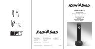
<strong>Evolution</strong> <strong>DX2</strong> <strong>Controller</strong> Front Panel<br />
The <strong>Evolution</strong> <strong>DX2</strong> <strong>Controller</strong> Touch Key Front Panel provides<br />
all the necessary functions and control to operate and program<br />
the <strong>Evolution</strong> <strong>DX2</strong> <strong>Controller</strong>.<br />
Figure 2-1: <strong>Evolution</strong> <strong>DX2</strong> <strong>Controller</strong> Front Panel identifies the<br />
location of all touch keys and features.<br />
REMOTE<br />
CONTROL<br />
SAT 09:15:11AM VALID PGM: NONE<br />
05/01/93 WK1 [F1]=MAIN MENU<br />
CONTRAST<br />
PROGRAM<br />
ON/OFF<br />
<br />
F1<br />
F2<br />
F3<br />
SAT<br />
7 8 9<br />
LANGUAGE<br />
<br />
F4<br />
F5<br />
QUIT<br />
F6<br />
WED<br />
4<br />
SUN<br />
1<br />
THU<br />
5<br />
MON<br />
2<br />
FRI<br />
6<br />
TUE<br />
3<br />
0<br />
ENTER<br />
Figure 2: <strong>Evolution</strong> <strong>DX2</strong> <strong>Controller</strong> Face Panel<br />
The <strong>Evolution</strong> <strong>DX2</strong> <strong>Controller</strong> Front Panel provides the<br />
following features:<br />
• The display contains 2 lines, each line capable of<br />
displaying 40 characters.<br />
• Combination Day/Numeric Key Pad.<br />
• Enter Key - Executes all keypad entries.<br />
• Six Function keys used to select all program menus.<br />
• Full Range Display Contrast Control.<br />
Page 10<br />
Chapter 2: System Basics
Rain Master <strong>Irrigation</strong> Systems<br />
<strong>DX2</strong> User <strong>Manual</strong><br />
• Program On/Off - Executes or stops any program.<br />
• Ability to select English or Spanish language.<br />
• Up/Down Arrow Keys allow advancement through<br />
menus.<br />
• Immediate return to the base screen, using the Quit key.<br />
• Distinctive beep validates each key entry (Touch Tone).<br />
• Built-in Remote Control Connector.<br />
The display screen changes accordingly to the activity being<br />
performed.<br />
Chapter 2: System Basics Page 11
Rain Master <strong>Irrigation</strong> Systems<br />
<strong>DX2</strong> User <strong>Manual</strong><br />
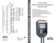
Base Screen<br />
After controller initialization (see Chapter 3), the base screen,<br />
depicted in Figure 2-2, is displayed.<br />
SAT 09:15:11AM VALID PGM: NONE<br />
06/18/96 WK1 |F1|=MAIN MENU<br />
Figure 3: Base Screen<br />
• To alter the contrast of the display, use the Contrast<br />
keys.<br />
• The base screen displays the day, time, date and<br />
additional information, depending upon how the<br />
controller is configured.<br />
• The VALID PGM: section of the screen alternates every<br />
seven seconds, displaying either the program number(s)<br />
or the satellite address. All existing programs will be<br />
listed.<br />
Dashed program numbers such as (2 -5) indicate a range<br />
of programs which includes all numbers within the<br />
range.<br />
Numbers separated by commas such as (2, 4, and 6)<br />
indicate individual program numbers.<br />
• When the <strong>Evolution</strong> <strong>DX2</strong> controller displays the base<br />
screen information, the controller functions in the<br />
"automatic mode," meaning that any valid program(s)<br />
will automatically start at established program start<br />
time(s).<br />
• The manual function (see Chapter 8) disables the<br />
automatic mode. The controller has a built in time-out<br />
function (2 hour time-out) which returns the controller to<br />
the base screen (automatic mode) if the user<br />
inadvertently leaves the controller in some other screen.<br />
Page 12<br />
Chapter 2: System Basics
Rain Master <strong>Irrigation</strong> Systems<br />
<strong>DX2</strong> User <strong>Manual</strong><br />
• User prompts for valid keystroke entry are designated by<br />
| | (vertical bars) with the key name appearing<br />
between the bars.<br />
• The entry |F1|=MAIN MENU prompts the user to<br />
press the F1 key to access the Main Menu.<br />
• From the base screen, pressing F1 will display the main<br />
menu.<br />
Chapter 2: System Basics Page 13
Rain Master <strong>Irrigation</strong> Systems<br />
<strong>DX2</strong> User <strong>Manual</strong><br />
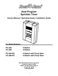
Main Menu<br />
The main menu indicates five of the function keys used to access<br />
different functions.<br />
|F1|=PROGRAM |F2|=ISC |F3|=STATUS<br />
|F4|=MANUAL & RAIN OFF |F5|=SETUP ||<br />
F Keys<br />
Up Arrow<br />
Figure 4: Main Menu<br />
Note:<br />
The F1 key, which was previously used to select the<br />
main menu, is now used to select the Program<br />
option. The use of the function keys changes<br />
depending upon the contents of the screen display.<br />
||<br />
This symbol in the main menu indicates you press<br />
the up arrow key on the controller to return to the<br />
previous display.<br />
In this case, the previous display is the base screen.<br />
The previous screen would change depending upon<br />
which menu options (function keys) you had<br />
previously chosen.<br />
Page 14<br />
Chapter 2: System Basics
Rain Master <strong>Irrigation</strong> Systems<br />
<strong>DX2</strong> User <strong>Manual</strong><br />
Using the <strong>Controller</strong> Keys<br />
Throughout this manual, the following symbols are used to<br />
represent the controller keys you use to move through the menu<br />
options and to view or change the settings of your <strong>Evolution</strong><br />
<strong>DX2</strong> controller.<br />
F1<br />
F2<br />
Press the associated function key (F1 to F6) to<br />
select the option shown on the display screen.<br />
<br />
<br />
Press the up arrow key to move to the<br />
previous screen.<br />
Press the down arrow key to move to the<br />
next screen.<br />
8<br />
5<br />
9<br />
6<br />
Use the numeric keypad section to enter<br />
numbers.<br />
1 2 3<br />
0<br />
ENTER<br />
SAT<br />
WED<br />
THU<br />
FRI<br />
Use the keypad section to enter days of the<br />
week.<br />
SUN<br />
MON<br />
TUE<br />
Chapter 2: System Basics Page 15
Rain Master <strong>Irrigation</strong> Systems<br />
<strong>DX2</strong> User <strong>Manual</strong><br />
Function Keys (continued):<br />
DARK<br />
LIGHT<br />
Press the DARK key to increase display<br />
contrast and the LIGHT key to decrease<br />
display contrast.<br />
Note: Maximum LIGHT setting will appear<br />
as a blank display.<br />
ENTER<br />
The ENTER key is used to complete entry of a<br />
number or day of the week. For example, to<br />
ENTER the number 1, press the 1 key and then<br />
press the ENTER key.<br />
QUIT<br />
Press the QUIT key to immediately go to the base<br />
screen. The QUIT key bypasses any previous<br />
screens and displays the base screen.<br />
LANGUAGE<br />
Press LANGUAGE to change from English to<br />
Espanol or from Espanol to English.<br />
PROGRAM<br />
ON/OFF<br />
Press the PROGRAM ON/OFF key to<br />
immediately turn a program on or off.<br />
Page 16<br />
Chapter 2: System Basics
Rain Master <strong>Irrigation</strong> Systems<br />
<strong>DX2</strong> User <strong>Manual</strong><br />
"Beep" Responses<br />
To provide user feedback for keyboard entry, two different beeps<br />
or tones are omitted. A single beep indicates a valid or correct<br />
entry. Rapid successive beeps indicate an invalid entry. For<br />
example, from the base screen, select|F1|and a single beep is<br />
heard. This indicates|F1|is a valid selection. However, from<br />
the base screen select the down arrow and multiple beeps are<br />
heard.<br />
System Configuration<br />
The <strong>DX2</strong> <strong>Evolution</strong> <strong>Controller</strong> is housed in an all weather<br />
enclosure containing the following assemblies:<br />
• Keyboard Main Panel Assembly<br />
• Main Power Switch Box Assembly<br />
• Master Valve/Pump/Power Board Assembly<br />
• Station Output Board Assembly<br />
(Quantity varies depending on station configuration)<br />
• Communication Board Assembly (Optional)<br />
• Sensor Terminal Board Assembly (Optional)<br />
Keyboard Main Panel<br />
The Keyboard Main Panel assembly consists of a main<br />
microprocessor control board and an optional sensor control<br />
board, which would attached to the main board. Four cables<br />
from this assembly provide the connections to the additional<br />
internal assemblies which include the Master Valve/Pump/Power<br />
board, the Communications board (optional), the Sensor<br />
Terminal (optional), and the Station Output board(s).<br />
Chapter 2: System Basics Page 17
Rain Master <strong>Irrigation</strong> Systems<br />
<strong>DX2</strong> User <strong>Manual</strong><br />
Main Power Switch Box<br />
The Main Power Switch Box assembly contains the controller<br />
main power switch, a dual ground fault interrupter receptacle and<br />
a step-down transformer delivering 12 VAC and 24 VAC.<br />
The ground fault interrupter (GFI) provides an exclusive safety<br />
feature against electrical power hazards. The GFI can sense and<br />
detect any degree of power line shorts and will immediately shut<br />
down the power preventing electrical damage or injury. The GFI<br />
includes a Test switch and a Reset switch. When the Test switch<br />
is pressed, all power will shut down indicating proper operation<br />
of the internal control circuitry. Pressing the Reset switch will<br />
restore power operation. The diagram of Figure 2-5: identifies<br />
the Main Power Switch Box and associated wiring.<br />
Master Valve/Pump/Power Board<br />
The Master Valve/Pump/Power board provides the four outputs<br />
for Master Valve 1, Master Valve 2, Normally Open Valve and<br />
Pump. Additionally, the assembly distributes the 12 VAC and<br />
24 VAC through their respective fuses to the associated<br />
controller assemblies. Figure 2-6: illustrates typical connections<br />
for Master Valve and Station connections.<br />
Station Output Board<br />
The Station Output board delivers the 24 VAC required<br />
operating valve solenoids, lighting systems, security systems,<br />
etc. A Station Output board may be configured with six stations<br />
or 12 stations. The controller enclosure will accept a maximum<br />
of four output boards providing control for a total of up to 48<br />
stations.<br />
Each board is equipped with two common terminals used for<br />
circuit ground return. All common terminals of a multiple<br />
station configuration are essentially identical and may be<br />
interchanged among the boards for wiring convenience.<br />
Page 18<br />
Chapter 2: System Basics
Rain Master <strong>Irrigation</strong> Systems<br />
<strong>DX2</strong> User <strong>Manual</strong><br />
Communication Board (optional)<br />
The Communication Board provides the means for<br />
communication among controllers and/or the Central Computer.<br />
The available communication options are Hardwire, Radio or<br />
Phone, communication provides the capability for any number of<br />
configurations.<br />
Sensor Terminal Board (optional)<br />
The Sensor Terminal board provides the direct link between the<br />
flow sensors, and/or weather station devices and the controller.<br />
The flow and weather sensing option provides four sets of<br />
terminal connections; two inputs for flow sensors (or one flow<br />
and one ET), one input for a rain sensor and one input for a wind<br />
sensor. All inputs are dedicated and calibrated to their respective<br />
weather devices.<br />
Chapter 2: System Basics Page 19
Rain Master <strong>Irrigation</strong> Systems<br />
<strong>DX2</strong> User <strong>Manual</strong><br />
<strong>DX2</strong> Pedestal <strong>Controller</strong> Assembly Layout<br />
The assembly layout location within the controller enclosure is<br />
depicted in Figure 2-4.<br />
1 - Keyboard Main Panel<br />
2 - Main Power Switch Box<br />
3 - MV/Pump/Power Bd.<br />
4 - Station Output Bd.<br />
5 - Communications Bd.<br />
6 - Sensor Terminal Bd.<br />
Rear<br />
Front<br />
Figure 5: Pedestal <strong>Controller</strong> Assembly Layout<br />
Page 20<br />
Chapter 2: System Basics
Rain Master <strong>Irrigation</strong> Systems<br />
<strong>DX2</strong> User <strong>Manual</strong><br />
Figure 6: AC Power Supply Wiring Diagram<br />
Chapter 2: System Basics Page 21
Rain Master <strong>Irrigation</strong> Systems<br />
<strong>DX2</strong> User <strong>Manual</strong><br />
MASTER<br />
VALVE<br />
ZONE 2<br />
VALVE<br />
PC<strong>DX2</strong>-MV<br />
PC<strong>DX2</strong>-OT12<br />
BLUE<br />
12VAC<br />
ORANGE<br />
24VAC<br />
MV1 MV2 N.O. PUMP COM<br />
STATION 2<br />
1 2 3 4 5 6 7 8 9 10 11 12<br />
COM<br />
TO MASTER VALVE<br />
TO ZONE 2 VALVE<br />
DWG DXMV10A<br />
Figure 7: Master Valve and Station Connection<br />
Page 22<br />
Chapter 2: System Basics
Rain Master <strong>Irrigation</strong> Systems<br />
Chapter 3<br />
Getting Started<br />
<strong>DX2</strong> User <strong>Manual</strong><br />
When a controller is new from the factory, when it is repaired,<br />
or updated, the controller must be initialized. This process must<br />
be performed before any programming or operations take place.<br />
The initialization process is unique in that the sequence of entries<br />
provides default settings for all programs of the controller.<br />
When all entries are completed, the initialization screens will no<br />
longer be available; however, settings may be changed later by<br />
referring to the instructions given in Chapter 4: Setup.<br />
Alternatively, changes to initialization are also possible<br />
(assuming it has not completed), by turning the power off then<br />
on, this restarts the entire procedure.<br />
Initialization Procedure<br />
Step 1<br />
Apply power to the controller and the Language<br />
options are displayed.<br />
Note:<br />
It may be necessary to adjust the contrast in the<br />
display by using the DARK and LIGHT front panel<br />
keys.<br />
|F1|=ENGLISH<br />
|F2|=ESPANOL<br />
Figure 8: Language Selection<br />
Chapter 3:<br />
Getting Started<br />
Chapter 3: Getting Started Page 23
Rain Master <strong>Irrigation</strong> Systems<br />
<strong>DX2</strong> User <strong>Manual</strong><br />
Step 2<br />
Step 3<br />
There are two options:<br />
• F1=ENGLISH - displays all controller menus<br />
and settings in English.<br />
• F2=ESPANOL - displays all controller menus<br />
and settings in Spanish.<br />
Select F1=ENGLISH. The menu changes to the<br />
YEAR Entry display.<br />
Enter the YEAR, and then press ENTER. Four<br />
numbers must be entered, as depicted in Figure 3-2.<br />
YEAR: __<br />
ENTER YEAR (yyyy)<br />
Figure 9: Year Entry<br />
Step 4<br />
Enter the MONTH. Use 1 for January, 2 for<br />
February, etc., and then press ENTER, as depicted in<br />
Figure 3-3.<br />
MONTH:<br />
ENTER MONTH (1-12)<br />
Figure 10: Month Entry<br />
Step 5<br />
Enter the DAY OF THE MONTH. The day must be<br />
between 1 and 31, and then press ENTER, as<br />
depicted in Figure 3-4.<br />
DAY OF THE MONTH:<br />
ENTER DAY OF THE MONTH (1-31)<br />
Figure 11: Day of the Month Entry<br />
Page 24<br />
Chapter 3: Getting Started
Rain Master <strong>Irrigation</strong> Systems<br />
<strong>DX2</strong> User <strong>Manual</strong><br />
Step 6<br />
Select the DAY of the week from the keypad<br />
numbers 1 through 7 (Sun through Sat), then press<br />
ENTER, as depicted in Figure 3-5.<br />
DAY:<br />
ENTER DAY OF THE WEEK |SUN|-|SAT|<br />
Figure 12: Day of the Week Entry<br />
Step 7<br />
Enter the TIME in hours and minutes (HH:MM).<br />
Select function key F1 to toggle from AM to PM, as<br />
depicted in Figure 3-6.<br />
TIME: : AM<br />
ENTER TIME (HH:MM) |F1|= AM/PM<br />
Figure 13: Time of Day Entry<br />
Then press ENTER to advance to the Master Valve<br />
Options.<br />
Master Valve/Pump Program Default<br />
Options<br />
The final initialization screens establish default<br />
options for usage of a particular Master Valve and/or<br />
Pump. Once established, all 12 programs and all<br />
ISC's will be affected. Individual programs or ISC<br />
settings may be modified at any time by following<br />
the procedures given in Chapter 4: Setup. The<br />
Master Valve selections are as follows:<br />
• F1=MV1 - Master Valve 1 (Normally Closed)<br />
• F2=MV2 - Master Valve 2 (Normally Closed)<br />
Chapter 3: Getting Started Page 25
Rain Master <strong>Irrigation</strong> Systems<br />
<strong>DX2</strong> User <strong>Manual</strong><br />
• F3=N.O. - Normally Open Master Valve<br />
• F4= NONE - Master Valve Not Used<br />
Step 8<br />
Select the appropriate Master Valve configuration<br />
for a particular irrigation system, as depicted in<br />
Figure 3-7.<br />
IS THERE A MASTER VALVE<br />
|F1|= MV1 |F2|= MV2 |F3|= N.O. |F4|= NONE<br />
Figure 14: Master Valve Options<br />
Note:<br />
If F4=NONE is selected, the Pump display will not<br />
appear.<br />
Step 9<br />
Select the appropriate Pump configuration.<br />
F1 = Uses Pump<br />
F2 = No Pump Used<br />
USES NO PUMP<br />
|F1|= PUMP |F2|=NONE<br />
Figure 15: Pump Options<br />
Step 10<br />
This completes the initialization procedure. Verify<br />
the default base screen display has the correct<br />
information.<br />
TUE 04:53:06PM VALID PGM: NONE<br />
06/18/96 WK1 |F1|= MAIN MENU<br />
Figure 16: Base Screen Display<br />
Page 26<br />
Chapter 3: Getting Started
Rain Master <strong>Irrigation</strong> Systems<br />
<strong>DX2</strong> User <strong>Manual</strong><br />
The default base screen displays the current day, time and date.<br />
In addition, VALID PGM: NONE, |F1|=MAIN MENU and<br />
the current week of a 2 week watering schedule are also shown.<br />
• VALID PGM: NONE - indicates that there are currently<br />
no valid programs in the controller. See Chapter 5 for<br />
details on entering and changing <strong>Evolution</strong> <strong>DX2</strong><br />
irrigation programs.<br />
• |F1|=MAIN MENU - indicates you are to press the<br />
F1 key to display <strong>Evolution</strong> <strong>DX2</strong>'s Main Menu.<br />
Background information about menus and navigating<br />
through the menu displays is given in Chapter 2: System<br />
Basics. Complete details on using the menus are given in<br />
the subsequent sections of this manual.<br />
Chapter 3: Getting Started Page 27
Rain Master <strong>Irrigation</strong> Systems<br />
<strong>DX2</strong> User <strong>Manual</strong><br />
Creating a New Program<br />
To create a program, the following parameters must be<br />
set:<br />
• Program Number<br />
• Watering Day cycle<br />
• Start times<br />
• Station Run times<br />
Using the 2 week (14 day cycle), this sample program sets up the<br />
parameters as follows:<br />
Program 1<br />
Water Days Start Times Stations Run Time<br />
Week 1: Mon-Wed-Fri 2:00 AM 1 5 min.<br />
Week 2: Mon-Fri 10:00 PM 2 10 min.<br />
3 7 min.<br />
1<br />
SAT 09:15:11AM VALID PGM: NONE<br />
05/01/96 WK1 ׀F1׀ = MAIN MENU<br />
F1<br />
2<br />
׀׀<br />
=STATUS ׀F3 ׀ =ISC ׀F2 ׀ = PROGRAM ׀F1 ׀<br />
=SETUP ׀F5 ׀ MANUAL & RAIN OFF =׀F4 ׀<br />
F1<br />
3<br />
REVIEW=׀F2׀ PROGRAM = MODIFY PROGRAM ׀F1׀<br />
F3 ׀׀ CLEAR PROGRAM =׀F4׀ =NEW PROGRAM ׀F3׀<br />
4<br />
PROGRAM NUMBER: P<br />
ENTER PROGRAM NUMBER (1-12)<br />
F1 ׀׀<br />
ENTER<br />
5<br />
P1 = ׀F1׀ 14 DAY CYCLE SKIP=׀F2׀ BY DAY<br />
F1 ׀׀ =31 DAY CYCLE NOW=F1 ׀F3׀<br />
Page 28<br />
Chapter 3: Getting Started
Rain Master <strong>Irrigation</strong> Systems<br />
<strong>DX2</strong> User <strong>Manual</strong><br />
6<br />
P1: NONE TODAY: TUE WK2<br />
MON<br />
׀׀ ׀‣׀ ׀SAT׀ – ׀SUN׀DAYS ENTER WEEK 1 WATER<br />
2<br />
WED<br />
4<br />
FRI<br />
6<br />
ENTER<br />
‣<br />
7<br />
P1: NONE TODAY: SAT WK1<br />
׀׀ ׀‣׀ ׀SAT׀ – ׀SUN׀DAYS ENTER WEEK 2 WATER<br />
MON<br />
2<br />
FRI<br />
6<br />
ENTER<br />
‣<br />
8<br />
P1: START TIME 1: : AM<br />
׀׀ ׀‣׀ AM/PM=׀F1׀ (HH:MM) ENTER TIME<br />
MON<br />
2<br />
0 0 ENTER<br />
9<br />
P1: START TIME 2: : AM<br />
׀׀׀‣׀AM/PM=׀F1׀(HH:MM) ENTER TIME<br />
MON<br />
2<br />
0 0 0 F1<br />
ENTER<br />
‣<br />
10<br />
P1 =׀F1׀ STATION RUN TIME<br />
׀׀ ׀‣׀ QUICK STATION PROGRAMMING =׀F2׀<br />
F1<br />
11<br />
P1 STATION NUMBER:<br />
ENTER STATION NUMBER (1-48)<br />
׀׀<br />
SUN<br />
1<br />
ENTER<br />
12<br />
P1 STATION 01 RUN TIME: :<br />
ENTER TIME (HH:MM)<br />
׀׀<br />
THUR<br />
5<br />
ENTER<br />
13<br />
P1 STATION 02 RUN TIME: :<br />
ENTER TIME (HH:MM)<br />
׀׀<br />
F1 0 ENTER<br />
14<br />
P1 STATION 03 RUN TIME: :<br />
ENTER TIME (HH:MM)<br />
׀׀<br />
SAT<br />
7<br />
ENTER<br />
QUIT<br />
This completes Program 1 entry. Program 1 will start on its<br />
scheduled water days and start times. The base screen display<br />
will now show "VALID PGM: 1."<br />
Chapter 3: Getting Started Page 29
Rain Master <strong>Irrigation</strong> Systems<br />
<strong>DX2</strong> User <strong>Manual</strong><br />
Modify a Program<br />
This example demonstrates the methods of changing the<br />
parameters of an existing program.<br />
Example:<br />
To change start time#1 of program 1 to 3:15 A.M.<br />
and change the run time on station 2 to 5 minutes,<br />
perform the following entries:<br />
1<br />
SAT 09:15:11AM VALID PGM: 1<br />
05/01/96 WK1 ׀F1׀ = MAIN MENU<br />
F1<br />
2<br />
׀׀<br />
=STATUS ׀F3 ׀ =ISC ׀F2 ׀ = PROGRAM ׀F1 ׀<br />
=SETUP ׀F5 ׀ MANUAL & RAIN OFF =׀F4 ׀<br />
F1<br />
REVIEW=׀F2׀ PROGRAM = MODIFY PROGRAM ׀F1׀ 3<br />
׀׀ CLEAR PROGRAM =׀F4׀ =NEW PROGRAM ׀F3׀<br />
F1<br />
4<br />
PROGRAM NUMBER: P<br />
ENTER PROGRAM NUMBER (1-12)<br />
׀׀<br />
SUN<br />
1<br />
ENTER<br />
5<br />
P1 ׀F1׀ = PROGRAM START WATER=׀F2׀ DAYS<br />
׀׀ =SEND ׀F5׀ =PERCENT ׀F4׀ =STATIONS ׀F3׀<br />
F1<br />
6<br />
P1: START TIME1: 2:00 AMENTER TIME (HH:MM)<br />
AM/PM=׀F1׀<br />
׀׀ ׀‣׀<br />
TUE<br />
3<br />
SUN<br />
1<br />
THU<br />
5<br />
ENTER ‣<br />
7<br />
P1 =׀F1׀ PROGRAM START =׀F2׀ WATER DAYS<br />
׀׀ ׀‣׀ SEND =׀F5׀ PERCENT =׀F4׀ STATIONS =׀F3׀<br />
F3<br />
Page 30<br />
Chapter 3: Getting Started
Rain Master <strong>Irrigation</strong> Systems<br />
<strong>DX2</strong> User <strong>Manual</strong><br />
8<br />
P1 STATIONS: 1-3<br />
‣ ׀׀ ׀‣׀<br />
9<br />
P1 =׀F1׀ STATION RUN TIME<br />
F1 ׀׀ ׀‣׀ QUICK STATION PROGRAMMING =׀F2׀<br />
10<br />
P1 STATION NUMBER:<br />
ENTER STATION NUMBER (1-48)<br />
׀׀<br />
MON<br />
2<br />
ENTER<br />
11<br />
P1 STATION 02 RUN TIME: :10<br />
ENTER TIME (HH:MM)<br />
׀׀<br />
THU<br />
5<br />
ENTER<br />
QUIT<br />
Chapter 3: Getting Started Page 31
Rain Master <strong>Irrigation</strong> Systems<br />
<strong>DX2</strong> User <strong>Manual</strong><br />
Program On/Off<br />
This example demonstrates how to activate or deactivate a<br />
single program.<br />
Example:<br />
To activate Program 1, perform the following<br />
entries:<br />
SAT 09:15:11AM VALID PGM: 1<br />
05/01/96 WK1 ׀F1׀ = MAIN MENU<br />
PROGRAM<br />
ON/ OFF<br />
PROGRAM NUMBER:<br />
ENTER NUMBER (0-12) 0=ALL OFF<br />
SUN<br />
1<br />
ENTER<br />
Note:<br />
To deactivate a running program, repeat the same<br />
key strokes.<br />
Page 32<br />
Chapter 3: Getting Started
Rain Master <strong>Irrigation</strong> Systems<br />
<strong>DX2</strong> User <strong>Manual</strong><br />
<strong>Manual</strong> Station Test Cycle<br />
To test stations manually:<br />
All manual operations are performed through the <strong>Manual</strong> &<br />
Rain Off Menu.<br />
Note: Pressing QUIT will cease all manual operations.<br />
Example:<br />
Turn on all stations for 5 minutes.<br />
1<br />
SAT 09:15:11AM VALID PGM: 1<br />
05/01/96 WK1 ׀F1׀ = MAIN MENU<br />
F1<br />
2<br />
׀׀<br />
=STATUS ׀F3 ׀ =ISC ׀F2 ׀ = PROGRAM ׀F1 ׀<br />
=SETUP ׀F5 ׀ MANUAL & RAIN OFF =׀F4 ׀<br />
F4<br />
3<br />
MANUAL: ׀ ׀F1 = TEST ׀ ׀F2 = MULTI-STATION<br />
RAIN OFF =׀F4 ׀ =STATION ׀F3 ׀<br />
׀׀<br />
F1<br />
4<br />
OPERATION TIME PER STATION: :<br />
׀׀ (HH:MM) ENTER TIME PER STATION<br />
THU<br />
5<br />
ENTER<br />
Each station will operate one at a time in sequential order for the<br />
specified period of 5 minutes.<br />
Chapter 3: Getting Started Page 33
Rain Master <strong>Irrigation</strong> Systems<br />
<strong>DX2</strong> User <strong>Manual</strong><br />
Rain Shutdown<br />
Example:<br />
To place all irrigation programs in rain shutdown,<br />
perform the following:<br />
1<br />
SAT 09:15:11AM VALID PGM: 1<br />
05/01/96 WK1 ׀F1׀ = MAIN MENU<br />
F1<br />
2<br />
׀׀<br />
=STATUS ׀F3 ׀ =ISC ׀F2 ׀ = PROGRAM ׀F1 ׀<br />
=SETUP ׀F5 ׀ MANUAL & RAIN OFF =׀F4 ׀<br />
F4<br />
3<br />
MANUAL: ׀ ׀F1 = TEST ׀ ׀F2 = MULTI-STATION<br />
RAIN OFF =׀F4 ׀ =STATION ׀F3 ׀<br />
׀׀<br />
F4<br />
4<br />
= NO WATER WINDOW ׀F2 ׀ = RAIN SHUTDOWN ׀F1 ׀<br />
׀׀ =PROGRAMMABLE RAIN SHUTDOWN ׀F3 ׀<br />
F1<br />
5<br />
RAIN SHUTDOWN: OFF<br />
׀׀ MODE) = OFF (AUTOMATIC ׀F2 ׀ = ON ׀F1 ׀<br />
F1<br />
QUIT<br />
Note:<br />
The Rain Shutdown message will appear in the base<br />
screen.<br />
Page 34<br />
Chapter 3: Getting Started
Rain Master <strong>Irrigation</strong> Systems<br />
Chapter 4<br />
Setup<br />
<strong>DX2</strong> User <strong>Manual</strong><br />
Because all irrigation applications are not identical, the<br />
<strong>Evolution</strong> <strong>DX2</strong> controller has been designed to allow users to<br />
establish a wide variety of individual programmable options.<br />
These options include changing configuration of programs,<br />
Individual Station Control (ISC), irrigation stations, the<br />
controller, and sensors. The setup function provides the<br />
mechanism for tailoring the <strong>Evolution</strong> <strong>DX2</strong> controller operation<br />
to a specific irrigation application.<br />
Note:<br />
Factory defaults have been established to allow<br />
most users to skip the setup options and proceed to<br />
basic programming (Chapter 5: Program Entry).<br />
The following table summarizes the setup options<br />
and factory default values.<br />
Chapter 4:<br />
Setup<br />
Chapter 4: Setup Page 35
Rain Master <strong>Irrigation</strong> Systems<br />
<strong>DX2</strong> User <strong>Manual</strong><br />
System Defaults<br />
Table 1: Setup Options and System Defaults<br />
Setup Function Options Defaults<br />
Program<br />
Cycle Mode<br />
start times,<br />
continuous cycle<br />
start times<br />
Overlap Protection on, off on<br />
<strong>Irrigation</strong> Program yes, no yes<br />
Omit by Date on, off on<br />
Station Delay Time 0-255, 0=Off 0<br />
Time Format<br />
Water Limit Reached<br />
Master Valve Used<br />
Uses Pump<br />
State of Master Valve<br />
between Stations<br />
HH:MM,<br />
MM:SS<br />
give warning, stop<br />
watering<br />
MV1, MV2,<br />
normally open MV,<br />
none<br />
uses a pump, uses no<br />
pump<br />
on, off<br />
HH:MM<br />
give<br />
warning<br />
Dependent upon<br />
power-on<br />
initialization<br />
(see Chapter 3)<br />
Set at<br />
initialization<br />
(see Chapter 3)<br />
on<br />
Master Valve Delay<br />
Turn On Time<br />
0-600 seconds 0<br />
Page 36<br />
Chapter 4: Setup
Rain Master <strong>Irrigation</strong> Systems<br />
<strong>DX2</strong> User <strong>Manual</strong><br />
Table 1: Setup Options and System Defaults (continued)<br />
Setup Function Options Defaults<br />
ISC<br />
Cycle Mode<br />
start times, start times<br />
continuous cycle<br />
Overlap Protection on, off on<br />
<strong>Irrigation</strong> Program yes, no yes<br />
Omit by Date on, off on<br />
Station Delay Time 0-255, 0=Off 0<br />
Time Format HH:MM, MM:SS HH:MM<br />
Water Limit Reached give warning, stop<br />
watering<br />
give warning<br />
Master Valve Used<br />
MV1, MV2, Set at initialization<br />
normally open MV, (see Chapter 3)<br />
none<br />
Pump<br />
uses pump, uses no<br />
pump<br />
Set at initialization<br />
(see Chapter 3)<br />
State of Master Valve<br />
between Stations<br />
on, off<br />
on<br />
Master Valve Delay<br />
Turn On Time<br />
0-600 seconds 0<br />
Chapter 4: Setup Page 37
Rain Master <strong>Irrigation</strong> Systems<br />
<strong>DX2</strong> User <strong>Manual</strong><br />
Table 1: Setup Options and System Defaults (continued)<br />
Setup Function Options Defaults<br />
Stations<br />
Low Limit Flow<br />
Checking<br />
enable, disable<br />
disable<br />
Upper Limit Flow<br />
Checking<br />
enable, disable<br />
disable<br />
Low Limit Current Check enable, disable disable<br />
Upper Limit Current<br />
Check<br />
enable, disable<br />
enable<br />
Maximum Current Limit 0.0 to 1.0 amps 1.0<br />
Minimum Current Limit 0.0 to 1.0 amps 0.05<br />
Maximum Flow Limit<br />
0 to 2000 gallons<br />
per minute<br />
500<br />
Minimum Flow Limit<br />
0 to 2000 gallons<br />
per minute<br />
0<br />
Type normal, injector normal<br />
Page 38<br />
Chapter 4: Setup
Rain Master <strong>Irrigation</strong> Systems<br />
<strong>DX2</strong> User <strong>Manual</strong><br />
Table 1: Setup Options and System Defaults (continued)<br />
Setup Function Options Defaults<br />
<strong>Controller</strong><br />
Main Line Flow Limit<br />
0 to 2000 gallons<br />
per minute<br />
Monthly Water Limit 1-9,999,999<br />
gallons, none<br />
Flow Meter used for<br />
Limit Comparisons<br />
meter 1, meter 2,<br />
sum of meters 1<br />
and 2<br />
2000<br />
none<br />
meter 1<br />
Flow Delay before<br />
Limit Checks<br />
1-6 minutes 2 minutes<br />
Unscheduled Limit (0-2000) gallons 200<br />
Omit by Date<br />
(15 allowed)<br />
any day of the year<br />
none<br />
Time 12 hour, 24 hour 12 hour<br />
Date<br />
month/day/<br />
year, day/<br />
month/year<br />
month/day/<br />
year<br />
Language English, Espanol English<br />
Access Code none/set none<br />
Chapter 4: Setup Page 39
Rain Master <strong>Irrigation</strong> Systems<br />
<strong>DX2</strong> User <strong>Manual</strong><br />
Table 1: Setup Options and System Defaults (continued)<br />
Setup Functions Options Defaults<br />
Operational Modes<br />
satellite, submaster,<br />
Flow Max<br />
satellite<br />
Configuration<br />
Sensors<br />
Communications Type<br />
(If submaster is selected<br />
mode)<br />
Address<br />
(If submaster is selected<br />
mode)<br />
Program Assignment<br />
Moisture Sensor<br />
Radio/ wire<br />
Phone<br />
Trunk<br />
Radio/wire<br />
0-255 239<br />
1- 12 none<br />
Trip Points (1-12) 0-200 0<br />
Sensor Status enabled disabled disabled<br />
Flow 1- K Value 0-56000 0<br />
Flow 1- Offset Value 0-26000 0<br />
Flow 2- K Value 0-56000 0<br />
Flow 2- Offset Value 0-26000 0<br />
Page 40<br />
Chapter 4: Setup
Rain Master <strong>Irrigation</strong> Systems<br />
<strong>DX2</strong> User <strong>Manual</strong><br />
F1 Main Menu<br />
F5 Setup<br />
F1<br />
Program<br />
Program<br />
Setup Program is used to specify operational controls for the<br />
programs used by the <strong>Evolution</strong> <strong>DX2</strong>. The following parameters<br />
and options are available in the Setup Program:<br />
• Cycle Mode: Select start times or continuous cycle<br />
• Overlap Protection: Select station start time overlap<br />
• <strong>Irrigation</strong> Program: If NO is selected for a program,<br />
then the controller Rain Shutdown mode will not affect<br />
program operation.<br />
• Omit By Date Enable: Select non-watering dates.<br />
• Station Delay Time - Set delay time between station<br />
watering start times.<br />
• Time Format - Select time in hours and minutes or<br />
minutes and seconds.<br />
• At Water Limit - Select water control option to stop<br />
watering or give warning if water limit is exceeded.<br />
• Master Valve - Select master valve configuration.<br />
• Pump - Select pump configuration.<br />
• Master Valve On Between Stations - On or Off.<br />
• Master Valve Delay Turn On Time - Set delay of turn on<br />
time.<br />
Chapter 4: Setup Page 41
Rain Master <strong>Irrigation</strong> Systems<br />
<strong>DX2</strong> User <strong>Manual</strong><br />
The <strong>Evolution</strong> <strong>DX2</strong> <strong>Controller</strong> allows each program to have its<br />
own unique set of setup parameters. Individual setup parameters<br />
on a per program basis provide absolute programming<br />
independence.<br />
Program Setup Procedure<br />
Step 1 Advance to the program entry screen through the<br />
following sequence:<br />
F1=Main Menu<br />
F5=Setup<br />
F1=Program<br />
PROGRAM NUMBERS: P<br />
ENTER PROGRAM NUMBER (1-12)<br />
||<br />
Figure 17: Program Entry<br />
Step 2<br />
Step 3<br />
Enter the program number, the program number<br />
must be between 1 and 12, then press ENTER.<br />
Cycle Mode<br />
Press F1=CHANGE OPTION to select one of the<br />
two following options:<br />
• START TIMES - Start a program based upon<br />
user-defined (programmed) start times (up to 8<br />
start times available).<br />
• CONTINUOUS CYCLE - Allows a program to<br />
be run continuously during a user defined water<br />
window (start/end time). Upon completion of<br />
the first cycle, a user defined soak delay occurs<br />
and the program starts again. Operation repeats<br />
in this fashion until the end time is reached.<br />
Page 42<br />
Chapter 4: Setup
Rain Master <strong>Irrigation</strong> Systems<br />
<strong>DX2</strong> User <strong>Manual</strong><br />
P # CYCLE MODE: START TIMES<br />
|F1|=CHANGE OPTION<br />
|‣|||<br />
Figure 18: Cycle Mode<br />
Step 4<br />
Overlap Protection<br />
Press the Down Arrow to display the Overlap<br />
Protection option screen.<br />
Overlap protection prevents multiple stations from<br />
being on simultaneously if the station start times<br />
overlap.<br />
Select one of the two following options:<br />
• ON - Allows only one station to be on at a time,<br />
regardless of programmed start times.<br />
• OFF- Allows multiple stations to be on<br />
simultaneously if station start times overlap.<br />
P # CYCLE MODE: START TIMES<br />
|F1|=CHANGE OPTION<br />
|‣|||<br />
Figure 19: Overlap Protection<br />
Step 5<br />
<strong>Irrigation</strong> Program<br />
An <strong>Irrigation</strong> Program is defined as a watering<br />
program responding to rain shutdown features and<br />
Flow Max control.<br />
The IRRIGATION PROGRAM: YES option sets a<br />
program to respond to rain shutdown and features<br />
such as stop watering.<br />
Chapter 4: Setup Page 43
Rain Master <strong>Irrigation</strong> Systems<br />
<strong>DX2</strong> User <strong>Manual</strong><br />
The IRRIGATION PROGRAM: NO option<br />
disables commands associated with rain shutdown or<br />
stop watering. This option is primarily used for<br />
controlling lighting, security gates, water fountains,<br />
etc.<br />
Note:<br />
Selecting IRRIGATION PROGRAM: YES does not<br />
place the program into the Rain Shutdown mode.<br />
Refer to "Rain Off" page to place the controller<br />
into Rain Shutdown.<br />
Warning:<br />
<strong>Irrigation</strong> programs should be set to the Yes<br />
option for any watering configuration.<br />
Press the Down Arrow to display the <strong>Irrigation</strong><br />
Program option screen, and select the appropriate<br />
option.<br />
P # IRRIGATION PROGRAM: YES<br />
|F1|=CHANGE OPTION<br />
|‣|||<br />
Figure 20: <strong>Irrigation</strong> Program<br />
Step 6<br />
Omit By Date Enable<br />
OMIT BY DATE allows you to enter up to 15 dates,<br />
on which watering will NOT occur. The steps<br />
required to add/delete dates are detailed in the Omit<br />
By Date section. The Omit By Date option<br />
determines whether or not a program will run for the<br />
omitted dates entered into the controller.<br />
Page 44<br />
Chapter 4: Setup
Rain Master <strong>Irrigation</strong> Systems<br />
<strong>DX2</strong> User <strong>Manual</strong><br />
There are two options:<br />
• ON - Enables omitting by date (Program will not<br />
start on any omitted date).<br />
• OFF- Disables omitting by date (Program start<br />
will not be affected by Omit By Date entries).<br />
Press the Down Arrow to display the Omit By Date<br />
Enable option screen.<br />
Press F1=CHANGE OPTION to select the<br />
appropriate option.<br />
P # OMIT BY DATE ENABLE OPTION: OFF<br />
|F1|=CHANGE OPTION<br />
|‣|||<br />
Figure 21: Omit By Date Option<br />
Step 7<br />
Station Delay Time<br />
Use STATION DELAY TIME to specify "dead" time<br />
between stations being controlled by a program. For<br />
example, assume a program controls three stations<br />
and there is a station delay time of 10 seconds. After<br />
station 1 has completed its watering, the controller<br />
will wait 10 seconds before turning on station 2.<br />
When station 2 completes, the controller will delay<br />
another 10 seconds before starting station 3.<br />
The available delay is 0 to 255 seconds.<br />
Press the Down Arrow key to display the Station<br />
Delay Time screen.<br />
P # CYCLE MODE: START TIMES<br />
|F1|=CHANGE OPTION<br />
|‣|||<br />
Figure 22: Station Delay Time Display<br />
Chapter 4: Setup Page 45
Rain Master <strong>Irrigation</strong> Systems<br />
<strong>DX2</strong> User <strong>Manual</strong><br />
Step 8<br />
Enter the Station Delay Time.<br />
Time Format<br />
The time format for station run times can be<br />
established on a per program basis.<br />
There are two options, HH:MM (hours and minutes)<br />
and MM:SS (minutes and seconds).<br />
The MM:SS option allows precise station run time<br />
control, since the station can be programmed to the<br />
second.<br />
Press the Down Arrow key to display the Time<br />
Format screen.<br />
Select the Time Format using the F1=CHANGE<br />
OPTION toggle key.<br />
P # TIME FORMAT OPTION: HH:MM<br />
|F1|=CHANGE OPTION<br />
|‣|||<br />
Figure 23: Time Format<br />
Step 9<br />
Page 46<br />
At Water Limit<br />
There are two options.<br />
• Select GIVE WARNING to continue watering<br />
when the monthly water limit is reached. If the<br />
limit is exceeded, an entry is made in the<br />
Warning/Report list and irrigation continues (see<br />
Chapter 10).<br />
• Select STOP WATERING to cease watering<br />
when the monthly water limit is reached. If the<br />
limit is exceeded, an entry is made in the<br />
Warning/Report list and irrigation is stopped<br />
(see Chapter 10). No further irrigation occurs<br />
until a new month begins (and the monthly<br />
water total is reset).<br />
Chapter 4: Setup
Rain Master <strong>Irrigation</strong> Systems<br />
<strong>DX2</strong> User <strong>Manual</strong><br />
Press the Down Arrow key to display the At Water<br />
Limit screen.<br />
Select either Stop Watering or Give Warning using<br />
the F1=CHANGE OPTION toggle key.<br />
P # AT WATER LIMIT: STOP WATERING<br />
|F1|=CHANGE OPTION<br />
|‣|||<br />
Figure 24: At Water Limit<br />
Step 10<br />
Master Valve<br />
There are four options:<br />
• MV1 (Master Valve 1)<br />
• MV2 (Master Valve 2)<br />
• Normally Open MV<br />
• None<br />
Press the Down Arrow key to display the Master<br />
Valve selection screen.<br />
P # MASTER VALVE USED: MV1<br />
|F1|=CHANGE OPTION<br />
|‣|||<br />
Figure 25: Master Valve Selection<br />
Advance through the four selections using the<br />
F1=CHANGE OPTION key and select the<br />
appropriate Master Valve configuration.<br />
Note:<br />
If the NONE option is selected for Master Valve, no<br />
further Master Valve/Pump options will follow.<br />
Chapter 4: Setup Page 47
Rain Master <strong>Irrigation</strong> Systems<br />
<strong>DX2</strong> User <strong>Manual</strong><br />
Note:<br />
If a Normally Open Master Valve is selected, it will<br />
not be activated with the program. It will be<br />
energized only if the controller detects a main line<br />
or unscheduled overflow condition. In this<br />
condition, 24 VAC appears at the N.O. terminal<br />
board output, which turns the valve off.<br />
Step 11<br />
Pump<br />
There are two options:<br />
• Select Pump if the program is to operate with a<br />
pump.<br />
• Select No Pump if the program is to operate<br />
without a pump.<br />
Press the Down Arrow key to display the Pump<br />
selection screen.<br />
Select the Pump configuration using the<br />
F1=CHANGE OPTION toggle key.<br />
P # USES NO PUMP<br />
|F1|=CHANGE OPTION<br />
|‣|||<br />
Figure 26: Pump Selection<br />
Step 12<br />
Master Valve On Between Stations<br />
There are two options, ON and OFF.<br />
Select the appropriate configuration.<br />
MASTER VALVE IS ON BETWEEN STATIONS<br />
|F1|=CHANGE OPTION |‣|||<br />
Figure 27: Valve On/Off Between Stations<br />
Page 48<br />
Chapter 4: Setup
Rain Master <strong>Irrigation</strong> Systems<br />
<strong>DX2</strong> User <strong>Manual</strong><br />
Step 13<br />
Master Valve Delay Turn On Time<br />
Use MASTER VALVE DELAY TURN ON TIME<br />
to delay the activation of the master valve by 0 to<br />
600 seconds from the program starts time (one time<br />
delay).<br />
Press the Down Arrow key to display the Master<br />
Valve Delay Turn On Time entry screen.<br />
Enter the delay time then press ENTER. The time<br />
must be between 0 and 600 seconds.<br />
MASTER VALVE DELAY TURN ON TIME: 30<br />
ENTER TIME (0-600 SEC)<br />
|‣|||<br />
Figure 28: Valve Delay Turn On Time<br />
To end the Program Setup procedure, press the<br />
Down Arrow to return to the Setup Main Menu.<br />
To make changes or to configure another program<br />
number, press F1=PROGRAM and repeat Setup<br />
Program procedure. Advance through all menu<br />
screens using the Down Arrow.<br />
Chapter 4: Setup Page 49
Rain Master <strong>Irrigation</strong> Systems<br />
<strong>DX2</strong> User <strong>Manual</strong><br />
ISC (Individual Station Control)<br />
ISC is used to specify operational settings for the Individual<br />
Station Control (ISC) programs used by the <strong>Evolution</strong> <strong>DX2</strong>.<br />
The ISC setup options are given below. The options are<br />
identical to those given in the previous section, Setup Programs.<br />
Refer to the Setup Programs section for details on the ISC<br />
options.<br />
• Cycle Mode<br />
• Overlap Protection<br />
• Rain Shutdown<br />
• Omit By Date<br />
• Time Format<br />
• Water Limit Checking<br />
• Master Valve<br />
• Pump<br />
• Master Valve Delay Turn on Time<br />
Page 50<br />
Chapter 4: Setup
Rain Master <strong>Irrigation</strong> Systems<br />
<strong>DX2</strong> User <strong>Manual</strong><br />
Station Number Procedure<br />
Step 1<br />
Advance to the ISC program number entry screen<br />
through the following sequence:<br />
F1=Main Menu<br />
F5=Setup<br />
F2=ISC<br />
ISC NUMBER: ISC__<br />
|F1|=CHANGE OPTION (1-48)<br />
|‣|||<br />
Figure 29: ISC Program Number<br />
Step 2<br />
Enter the station number then press ENTER. The<br />
station number must be between 1 and 48.<br />
Note:<br />
The maximum number of stations is determined by<br />
the total stations installed in the controller. The<br />
maximum number will appear on the Station<br />
Number Entry Display screen.<br />
Step 3<br />
The ISC Options are identical to the Setup Program<br />
options. Refer to the Setup Program procedure to<br />
complete all ISC options.<br />
This completes the ISC procedure.<br />
Press the QUIT key to return to the base menu.<br />
Chapter 4: Setup Page 51
Rain Master <strong>Irrigation</strong> Systems<br />
<strong>DX2</strong> User <strong>Manual</strong><br />
F1 Main Menu<br />
F5 Setup<br />
F3<br />
Stations<br />
Stations<br />
Setup Stations is used to enable/disable flow and current limit<br />
checking and to specify operational controls for the programs<br />
used by <strong>Evolution</strong> <strong>DX2</strong>.<br />
Flow checking is used to determine if a pipe has failed (broken,<br />
clogged) or if the monthly watering limit (budget) has been<br />
exceeded. Current checking is used to determine if there is a<br />
short or break in field wiring or if an out-of-tolerance or<br />
marginal field wiring problem exists. See Appendix A for<br />
complete details on flow limit checking and Appendix B for<br />
details on current limit checking. The following station options<br />
are:<br />
• Limit Checking - Enables or disables upper and<br />
lower limits of both Water Flow<br />
and Current.<br />
• Limits/Type - Enter upper and lower limits of<br />
Flow and Current. Select Type as<br />
Normal or Injector. Injector type<br />
is defined as a fertilizer<br />
application station.<br />
• Auto Limits - Establishes upper and lower limits<br />
of Flow and Current by measuring<br />
each station. An upper and lower<br />
percentage of the measurements<br />
Page 52<br />
Chapter 4: Setup
Rain Master <strong>Irrigation</strong> Systems<br />
<strong>DX2</strong> User <strong>Manual</strong><br />
are calculated to automatically set<br />
the limits for each station.<br />
Stations Setup<br />
Enable/Disable Limit Checking Procedure<br />
Step 1 Advance to the Limits Option Menu through the<br />
following sequence:<br />
F1=Main Menu<br />
F5=Setup<br />
F2=ISC<br />
Flow and Current Limit Checking is enabled or<br />
disabled with this option.<br />
|F1|=ENABLE/DISABLE LIMIT CHECKING<br />
|F2|=LIMITS/TYPE |F3|=AUTO LIMITS ||<br />
Figure 30: Station Limits Options<br />
Step 2<br />
Select F1=Enable/Disable Limit Checking.<br />
|F1|=FLOW<br />
|F2|=CURRENT<br />
||<br />
Figure 31: Flow/Current Selection<br />
There are two options:<br />
• Select FLOW to enable or disable water flow<br />
limit checking.<br />
• Select CURRENT to enable or disable electrical<br />
current limit checking.<br />
Chapter 4: Setup Page 53
Rain Master <strong>Irrigation</strong> Systems<br />
<strong>DX2</strong> User <strong>Manual</strong><br />
Step 3<br />
Step 4<br />
Select F1=FLOW.<br />
There are two options:<br />
• Select UPPER LIMIT to enable or disable Upper<br />
Limit Flow Checking.<br />
• Select LOWER LIMIT to enable or disable<br />
Lower Limit Flow Checking.<br />
Select F1=UPPER LIMIT.<br />
UPPER LIMIT CHECK: ENABLED<br />
|F1|=CHANGE OPTION<br />
||<br />
Figure 32: Upper Limit Check<br />
Step 5<br />
Step 6<br />
There are two options:<br />
• ENABLED<br />
• DISABLED<br />
Change the option displayed using the<br />
F1=CHANGE OPTION toggle key.<br />
Press the Up Arrow key to return to the Limit<br />
Selection screen and select F2=LOWER LIMIT.<br />
LOWER LIMIT CHECK: ENABLED<br />
|F1|=CHANGE OPTION<br />
||<br />
Figure 33: Lower Limit Check<br />
There are two options:<br />
• ENABLED<br />
• DISABLED<br />
Page 54<br />
Chapter 4: Setup
Rain Master <strong>Irrigation</strong> Systems<br />
<strong>DX2</strong> User <strong>Manual</strong><br />
Step 7<br />
Change the option displayed using the<br />
F1=CHANGE OPTION toggle key.<br />
If Electrical Current (enable/disable options) requires<br />
modification, use the Up Arrow key to select the previous<br />
screen.<br />
Repeat the Limit Checking procedure for Current Limits options<br />
by selecting Current rather than Flow.<br />
At the end of Limit Checking procedure, press the QUIT key to<br />
return to the base screen.<br />
Limits/Type Procedure<br />
This procedure applies to either the Station Number outputs or<br />
the Master Valve/Pump outputs. Either parameter may be<br />
configured at any time independently of each other.<br />
The Station/Master Valve Number Entry screen is a dual purpose<br />
menu which accepts two separate entries. The Station Number<br />
output is selected by entering any number between 1 and 48<br />
(maximum number is limited by the number of stations<br />
installed).<br />
The Master Valve/Pump output configuration is selected by any<br />
number between 1 and 4 which is preceded by a 0 (zero). The<br />
Master Valve/Pump selections are:<br />
• MV1=01<br />
• MV2=02<br />
• N.O.=03<br />
• Pump=04<br />
Note:<br />
Entries from 05 to 09 will be accepted as station<br />
number outputs.<br />
Chapter 4: Setup Page 55
Rain Master <strong>Irrigation</strong> Systems<br />
<strong>DX2</strong> User <strong>Manual</strong><br />
Step 1<br />
Advance to the Station Number/Master Valve Entry<br />
screen through the following sequence:<br />
F1=Main Menu<br />
F5=Setup<br />
F3=Stations<br />
F2=Limits/Type<br />
STATION NUMBER:<br />
ENTER STATION NUMBER (1-48, OX=MV)<br />
||<br />
Figure 34: Limits/Type<br />
Note:<br />
The Station Numbers relate to the individual station<br />
outputs whereas the Master Valve selection relates<br />
to the complete irrigation system configuration.<br />
These entries should be considered as two<br />
independent parameters.<br />
Step 2<br />
Enter the station number then press ENTER. The<br />
Number must be between 1 and 48.<br />
Note:<br />
The maximum number of stations is determined by<br />
the total stations installed in the associated satellite<br />
controller. The maximum number will appear on<br />
the Station Number Entry Display screen.<br />
Step 3<br />
Select F1=CURRENT LIMIT from the three options<br />
in the following display:<br />
Page 56<br />
Chapter 4: Setup
Rain Master <strong>Irrigation</strong> Systems<br />
<strong>DX2</strong> User <strong>Manual</strong><br />
|F1|=CURRENT LIMIT |F2|=FLOW LIMIT<br />
|F3|=TYPE<br />
||<br />
Figure 35: Limit Options<br />
The three options are:<br />
• CURRENT LIMIT - Set up limits for<br />
electrical current checking.<br />
• FLOW LIMIT- Set up limits for flow<br />
checking.<br />
• TYPE - Select station type (NORMAL, or<br />
INJECTOR).<br />
Step 4<br />
Enter the maximum current limit for the station. The<br />
limit must be between 0.0 and 1.0 amp, and then<br />
press ENTER.<br />
`<br />
STATION ## MAX CURRENT LIMIT: 1.00<br />
ENTER LIMIT (0.0-1.0 AMPS)<br />
||<br />
Figure 36: Max Current Limit<br />
Step 5<br />
Enter the minimum current limit for the station in<br />
the Minimum Current display screen. The limit<br />
must be between 0.0 and 1.0 amp, and then press<br />
enter.<br />
Note: A nominal value of 0.05 amps of quiescent current<br />
is recommended for the Minimum Current entry to<br />
ensure that an open output circuit would be<br />
detected.<br />
Chapter 4: Setup Page 57
Rain Master <strong>Irrigation</strong> Systems<br />
<strong>DX2</strong> User <strong>Manual</strong><br />
STATION ## MIN CURRENT LIMIT: .05<br />
ENTER LIMIT (0.0-1.0 AMPS)<br />
||<br />
Figure 37: Min Current Limit<br />
<strong>Controller</strong> returns to the limit options display.<br />
Step 6<br />
Select F2=FLOW LIMIT from the three option<br />
menu.<br />
Enter the maximum flow limit for the station. The<br />
limit must be between 0 and 2000 gallons per minute<br />
(GPM). Press ENTER.<br />
<strong>Controller</strong> returns to the Limit Options display<br />
STATION ## MAX FLOW LIMIT: 500<br />
ENTER MAX LIMIT (0-2000)<br />
||<br />
Figure 38: Max Flow Limit<br />
Step 7<br />
Enter the minimum flow limit for the station. The<br />
limit must be between 0 and 2000 gallons per minute<br />
(GPM), then press ENTER.<br />
STATION ## MIN FLOW LIMIT:<br />
ENTER MIN LIMIT (0-2000)<br />
Figure 39: Min Flow Limit<br />
<strong>Controller</strong> returns to the Limit Options display.<br />
Page 58<br />
Chapter 4: Setup
Rain Master <strong>Irrigation</strong> Systems<br />
<strong>DX2</strong> User <strong>Manual</strong><br />
Step 8<br />
Select F3=TYPE. The present setting for the station<br />
is displayed.<br />
STATION # TYPE: NORMAL<br />
|F1|=NORMAL |F2|=INJECTOR<br />
||<br />
Figure 40: Station Type<br />
Step 9<br />
Step 10<br />
There are two options:<br />
• NORMAL<br />
• INJECTOR<br />
Select F1=NORMAL to change station type to<br />
Normal.<br />
Select F2=INJECTOR to change station type to<br />
Injector.<br />
Press the Up Arrow to return to the Station/Master<br />
Valve Number menu. Repeat as necessary.<br />
End of Limits/Type procedure.<br />
Press QUIT to return to the base screen.<br />
Chapter 4: Setup Page 59
Rain Master <strong>Irrigation</strong> Systems<br />
<strong>DX2</strong> User <strong>Manual</strong><br />
Note:<br />
Injector Station Operation<br />
The typical use of an injector station is to apply<br />
fertilizer to wet ground.<br />
When the user includes an injector assigned station<br />
in one or more programs, the controller will prompt<br />
for an injector delay time. The operation of a<br />
program using the injector delay time is best<br />
described with an example.<br />
Assume Program 1 uses injector station 10 with a<br />
programmed injector delay = 1 minute. Also<br />
assume program 1 has three NORMAL stations (1,<br />
2, 3) each with a run time of 5 minutes.<br />
Example: Injector station operation with a program start time of<br />
7:00 A.M.<br />
7:00 AM Master Valve ON<br />
Station 1<br />
ON<br />
7:01 Station 10 ON<br />
7:05 Station 1 OFF<br />
Station 2<br />
ON<br />
7:10 Station 2 OFF<br />
Station 3<br />
ON<br />
7:15 All Stations and MV OFF<br />
Page 60<br />
Chapter 4: Setup
Rain Master <strong>Irrigation</strong> Systems<br />
<strong>DX2</strong> User <strong>Manual</strong><br />
Main Flow Procedure<br />
This procedure establishes the maximum flow limit for the<br />
complete controller irrigation system. The accepted flow limit<br />
range is 0-2000 gallons per minute (GPM). The GPM value is<br />
determined by the user by calculating the expected amount of<br />
water usage at any given time in the watering configuration. A<br />
safety margin of 20% above the determined value is<br />
recommended.<br />
Calculation Example:<br />
For an irrigation system that delivers a maximum flow of<br />
1000 GPM at any given time throughout the complete<br />
watering program, the Main Flow Limit would be 1200<br />
GPM. (1000 + 20%) = (1000+(1000x.20=200) = 1200)<br />
Flow Max Main Line Limits<br />
In a Flow Max system, the total GPM of all participating<br />
controllers is calculated into the overall Main Flow Limit value.<br />
The Main Flow Limit is entered at the submaster controller only.<br />
For any number of controllers within a Flow Max group, there<br />
will only be one main flow limit. Remember that the main flow<br />
limit must be higher than an expected flow under normal<br />
operation yet low enough to react when a main break occurs.<br />
Chapter 4: Setup Page 61
Rain Master <strong>Irrigation</strong> Systems<br />
<strong>DX2</strong> User <strong>Manual</strong><br />
Procedure<br />
Step 1<br />
Advance to the Station Number/Master Valve Entry<br />
screen through the following sequence:<br />
F1=Main Menu<br />
F5=Setup<br />
F3=Stations<br />
F2=Limits/Type<br />
STATION NUMBER:<br />
ENTER STATION NUMBER (1-48, OX=MV)<br />
||<br />
Figure 41: Main Flow Limit Entry<br />
Step 2<br />
Enter 01 (zero 1) then press ENTER. The main limit<br />
option menu is depicted in Figure 4-26:<br />
|F1|=CURRENT LIMIT |F2|=FLOW LIMIT<br />
||<br />
Figure 42: Main Limit Options<br />
Step 3<br />
Select F2=FLOW LIMIT. The maximum main flow<br />
limit is displayed (the default value is 2000 GPM).<br />
MAIN FLOW MAX FLOW LIMIT: 2000<br />
ENTER MAX LIMIT (0-2000)<br />
||<br />
Figure 43: Main Flow Maximum Limit<br />
Step 4<br />
Enter the determined value for your system and then<br />
press the ENTER key. Press QUIT to return to the<br />
base screen.<br />
This completes the Main Flow Limit procedure.<br />
Page 62<br />
Chapter 4: Setup
Rain Master <strong>Irrigation</strong> Systems<br />
<strong>DX2</strong> User <strong>Manual</strong><br />
Auto Limits Procedure<br />
The Auto Limits feature establishes upper and lower limits of<br />
Flow and Current by constantly measuring each station. An<br />
upper and lower percentage of the measurements are calculated<br />
to automatically set the limits for each station.<br />
The current upper default percentage is set at 20% above the<br />
measured value (If the measured value is .50 Amps, the<br />
calculated value for the upper limit would be .60 Amps). The<br />
lower default percentage is set at 50% below the measured value<br />
(If the measured value is .50 Amps, the calculated value for the<br />
lower limit would be .25 Amps).<br />
The default values may be changed at any time using the<br />
F2=SET LIMIT (%) option. The percentage value ranges are<br />
given on the percentage entry display screen.<br />
Note:<br />
If the default values are not suitable for your<br />
application, the SET LIMITS percentages must be<br />
entered prior to running the Auto Limits. Select<br />
F2=SET LIMIT and set your percentages<br />
accordingly.<br />
Step 1<br />
Advance to the Limits/Type menu Auto Limits two<br />
options are displayed through the following key<br />
sequence:<br />
F1=Main Menu<br />
F5=Setup<br />
F3=Stations<br />
F2=Limits/Type<br />
|F1|=RUN AUTO LIMITS |F2|=SET LIMIT (%)<br />
||<br />
Figure 44: Auto Limits<br />
Chapter 4: Setup Page 63
Rain Master <strong>Irrigation</strong> Systems<br />
<strong>DX2</strong> User <strong>Manual</strong><br />
Step 2<br />
Select F1=RUN AUTO LIMITS and verify the<br />
following three option display:<br />
|F1|=FLOW ONLY |F2|=CURRENT ONLY<br />
|F3|=BOTH FLOW AND CURRENT ||<br />
Figure 45: Auto Limits<br />
There are three options:<br />
• Flow Only<br />
• Current Only<br />
• Both Flow and Current<br />
Step 3<br />
Select F1=Flow Only and enter the station number.<br />
The station number must be between 1 and 48. To<br />
measure all stations, enter station number 1, and then<br />
press ENTER.<br />
Note:<br />
The maximum number of stations is determined by<br />
the total stations installed in the controller. The<br />
maximum number (1-xx) will appear on the Station<br />
Number Entry Display.<br />
Each station will run for the full time period of the<br />
flow check delay time (1 to 6 minutes) before<br />
proceeding to the next station.<br />
The following display, as depicted in Figure 4-30,<br />
indicates the station number, run time count-down<br />
timer, station current measurement (I) and flow<br />
measurement (GPM). The upper and lower limits of<br />
flow are automatically calculated based on these<br />
measured parameters.<br />
Page 64<br />
Chapter 4: Setup
Rain Master <strong>Irrigation</strong> Systems<br />
<strong>DX2</strong> User <strong>Manual</strong><br />
When the count-down timer is zero, the station<br />
number will increment to the next station and the<br />
measurement process is repeated. When all stations<br />
are complete, the display returns to the three option<br />
selection screen. At this point, all upper and lower<br />
percentage values have been calculated.<br />
Note: The default measuring time for each station is two<br />
minutes. This time period accounts for the Flow<br />
Delay time allowing water flow pressure to stabilize.<br />
AUTO LIM STA 1<br />
0:02:00 I=0.00 GPM=0<br />
||<br />
Figure 46: Auto Limits<br />
Step 4<br />
Select F2=CURRENT ONLY and enter the station<br />
number. The station number must be between 1- 48.<br />
To measure all stations, enter station number 1, and<br />
then press ENTER.<br />
The Current measuring default time is 5 seconds for<br />
each station. The calculating program is identical to<br />
the Flow mode. In addition to sequencing through all<br />
stations, MV1, MV2 and the N.O. output currents<br />
are also established.<br />
Note:<br />
The pump is not calculated and therefore should be<br />
established by the user manually.<br />
When completed, the Auto Limits Options menu<br />
will be displayed.<br />
Chapter 4: Setup Page 65
Rain Master <strong>Irrigation</strong> Systems<br />
<strong>DX2</strong> User <strong>Manual</strong><br />
Step 5<br />
Repeat procedure selecting F3=BOTH FLOW AND<br />
CURRENT.<br />
This selection is identical to the previous steps with<br />
the Current measurements taking place on the first<br />
pass through the stations and the Flow<br />
measurements are taken on the second pass.<br />
When the flow measurement pass is completed, the<br />
Auto Limits Options will be displayed.<br />
This completes the Auto Limits procedure.<br />
Press QUIT key to return to the base screen.<br />
Page 66<br />
Chapter 4: Setup
Rain Master <strong>Irrigation</strong> Systems<br />
<strong>DX2</strong> User <strong>Manual</strong><br />
F1 Main Menu<br />
F5 Setup<br />
F4<br />
<strong>Controller</strong><br />
Setup <strong>Controller</strong><br />
Setup <strong>Controller</strong> is used to specify operational controls for the<br />
controller. The following options are available in the <strong>Controller</strong><br />
Setup:<br />
• FLOW OPTIONS - Set monthly limits, select<br />
meters for flow checking, specify<br />
the amount of time to delay<br />
before checking limits, and set<br />
unscheduled flow limits. See<br />
Appendix A for complete details<br />
on flow meter operation.<br />
• OMIT BY DATE - Select up to 15 dates, on which<br />
watering will not occur.<br />
• USER OPTIONS - Change the time and date, select<br />
the language for the display, and<br />
enter or change access codes<br />
(passwords) for using the<br />
controller. See Appendix E for<br />
additional details on access<br />
codes.<br />
Chapter 4: Setup Page 67
Rain Master <strong>Irrigation</strong> Systems<br />
<strong>DX2</strong> User <strong>Manual</strong><br />
• CONFIGURATION - Specify communications<br />
mode of the satellite, submaster<br />
or the Flow Max group.<br />
Flow Options Procedure<br />
Step 1 Advance to the <strong>Controller</strong> Flow Options menu<br />
through the following sequence:<br />
F1=Main Menu<br />
F5=Setup<br />
F4=<strong>Controller</strong><br />
|F1|=FLOW OPTIONS |F2|=OMIT BY DATE<br />
|F3|=USER OPTIONS |F4|=CONFIGURATION||<br />
Figure 47: <strong>Controller</strong> Options<br />
Step 2<br />
Select F1=Flow Options to display the following<br />
Limit options:<br />
|F1|=MONTHLY LIMIT |F2|=COMPARE LIMITS<br />
|F3|=DELAY LIMIT |F4|=UNSCHED LIMIT ||<br />
Figure 48: Limit Options<br />
Four options are displayed:<br />
• MONTHLY LIMIT<br />
• COMPARE LIMITS<br />
• DELAY LIMIT<br />
• UNSCHED LIMIT<br />
Page 68<br />
Chapter 4: Setup
Rain Master <strong>Irrigation</strong> Systems<br />
<strong>DX2</strong> User <strong>Manual</strong><br />
Step 3<br />
To change monthly water limit, select<br />
F1=MONTHLY LIMIT.<br />
The current monthly water limit of the controller is<br />
displayed.<br />
CONTROLLER MONTHLY WATER LIMIT: NONE<br />
ENTER LIMIT (1-9999999) F1=NONE ||<br />
Figure 49: Monthly Water Limit<br />
Note:<br />
If the monthly watering limit is reached, the<br />
controller can be programmed to either:<br />
1. Give Warning<br />
2. Stop Watering<br />
See "At Water Limit"<br />
Step 4<br />
Enter the limit, or press F1=NONE to enter no limit.<br />
The limit must be between 1 and 9999999.<br />
Note:<br />
Water units are specified in gallons.<br />
Step 5<br />
Press the Up Arrow to return to the Limit Options<br />
screen.<br />
Flow Meter Compare Limit Selection<br />
Select F2=COMPARE LIMITS. The flow meter<br />
currently being used is displayed.<br />
Chapter 4: Setup Page 69
Rain Master <strong>Irrigation</strong> Systems<br />
<strong>DX2</strong> User <strong>Manual</strong><br />
FLOW METER USED: FLOW #1<br />
|F1|=CHANGE OPTION<br />
||<br />
Figure 50: Flow Meter Selection<br />
There are three options:<br />
• FLOW METER #1- Station flow rate limit<br />
checking will use data provided by FLOW<br />
METER #1. Accumulated water totals by<br />
FLOW METER #1 are used for comparison to<br />
the Monthly Water Limit specified in the<br />
previous step.<br />
• FLOW METER #2 - Operation is identical to<br />
Flow Meter #1. Accumulated water totals by<br />
FLOW METER #2 are compared to the<br />
specified Monthly Water Limit.<br />
• SUM OF FLOW #1 + FLOW #2 - Selecting<br />
sum of both meters indicates that the controller<br />
will take the accumulation total of FLOW<br />
METER #1 and add it to the accumulation total<br />
of FLOW METER #2. The result will be<br />
compared to the Monthly Water Limit.<br />
Additionally, station flow rates (measured in<br />
GPM) will also be summed and compared.<br />
Step 6<br />
Select the appropriate option using the<br />
F1=CHANGE OPTION key.<br />
Press the Up Arrow key to return to the Limit<br />
Options display.<br />
Page 70<br />
Chapter 4: Setup
Rain Master <strong>Irrigation</strong> Systems<br />
<strong>DX2</strong> User <strong>Manual</strong><br />
Step 7<br />
Delay Limit<br />
The Delay Limit sets a delay time (in minutes) prior<br />
to taking measurements to allow for stabilization of<br />
water lines.<br />
Select F3=DELAY LIMIT from the Limit Options<br />
display.<br />
DELAY TIME: 3<br />
ENTER TIME (1-6 MIN)<br />
||<br />
Figure 51: Delay Limit Time<br />
Step 8<br />
Step 9<br />
Enter the delay time. The delay must be a value<br />
between 1 and 6 minutes. Press ENTER to return to<br />
Limit Options screen.<br />
Unscheduled Limit<br />
The Unsched Limit option sets the maximum<br />
unscheduled water flow which can occur before an<br />
alarm or shut-down occurs.<br />
Select F4=UNSCHED LIMIT to display the<br />
following screen:<br />
UNSCHED FLOW LIMIT: 300<br />
ENTER LIMIT (0-2000)<br />
||<br />
Figure 52: Unsched Flow Limit<br />
Step 10<br />
Enter the Unscheduled Limit value. The limit must<br />
be between 0 and 2000 gallons then press ENTER.<br />
This completes the Flow Options procedure.<br />
Press the QUIT key to return to base menu.<br />
Chapter 4: Setup Page 71
Rain Master <strong>Irrigation</strong> Systems<br />
<strong>DX2</strong> User <strong>Manual</strong><br />
Omit By Date Procedure<br />
Step 1<br />
Advance to the <strong>Controller</strong> Omit By Date Options<br />
menu through the following sequence:<br />
F1=Main Menu<br />
F5=Setup<br />
F4=<strong>Controller</strong><br />
F2=Omit By Date<br />
OMISSION DATES (MONTH/DAY): NONE<br />
|F1|=DELETE |F2|=ADD |‣|||<br />
Figure 53: Omission Dates<br />
The date entered last is displayed. All prior dates may be viewed<br />
by pressing the Down Arrow key.<br />
Step 2<br />
Deleting dates<br />
Using the arrow keys to display the date to be<br />
deleted, then press the F1=DELETE key. Repeat<br />
procedure as necessary.<br />
Step 3<br />
Adding Dates<br />
Press the F2=ADD key. Enter the number of the<br />
month. Use 1 for January, 2 for February, etc., and<br />
then press ENTER.<br />
MONTH: 5<br />
ENTER MONTH (1-12)<br />
Figure 54: Month Entry<br />
Page 72<br />
Chapter 4: Setup
Rain Master <strong>Irrigation</strong> Systems<br />
<strong>DX2</strong> User <strong>Manual</strong><br />
Step 4<br />
Enter the day of the month. The day must be<br />
between 1 and 31, and then press ENTER.<br />
DAY OF THE MONTH: 15<br />
ENTER DAY OF THE MONTH (1-31)<br />
Figure 55: Day of the Month<br />
Step 5<br />
Step 6<br />
Repeat the F2=ADD DATE sequence to add<br />
additional dates, up to 15 dates may be entered.<br />
To review entered dates, use the Up Arrow key.<br />
This completes the Omit By Date procedure.<br />
Press QUIT to return to base screen.<br />
User Options Procedure<br />
The three available User Options are:<br />
• Time/Date<br />
• Language<br />
• Access Code<br />
Step 1 Advance to the User Options menu through the<br />
following sequence:<br />
F1=Main Menu<br />
F5=Setup<br />
F4=<strong>Controller</strong><br />
F3=User Options<br />
|F1|=TIME/DATE |F2|=LANGUAGE<br />
|F3|=ACCESS CODE<br />
||<br />
Figure 56: User Options<br />
Chapter 4: Setup Page 73
Rain Master <strong>Irrigation</strong> Systems<br />
<strong>DX2</strong> User <strong>Manual</strong><br />
Step 2<br />
Time/Date<br />
Select F1=TIME/DATE to display the two following<br />
options:<br />
• 12 HOUR display<br />
• 24 HOUR display<br />
| F1 | =12 HOUR (AM/PM) TIME DISPLAY<br />
| F2 | =24 HOUR TIME DISPLAY ||<br />
Figure 57: Time Format<br />
Step 3<br />
Step 4<br />
Press F1 to select 12 Hour (AM/PM) Time Display,<br />
or F2 to select 24 hour time display.<br />
Enter the current time in hours and minutes.<br />
If 12 hour format was selected, press the<br />
F1=AM/PM toggle key to select AM or PM.<br />
If you selected 24 hour format, 1 PM is 13:00, 2 PM<br />
is 14:00, etc.<br />
TIME: : _ AM<br />
ENTER TIME (HH:MM) |F1| =AM/PM ||<br />
Figure 58: Time Entry Format<br />
Step 5<br />
Press ENTER to advance to the Year Entry screen.<br />
Enter the year. Four digits must be entered<br />
YEAR:<br />
ENTER YEAR (YYYY)<br />
Page 74<br />
Chapter 4: Setup
Rain Master <strong>Irrigation</strong> Systems<br />
<strong>DX2</strong> User <strong>Manual</strong><br />
Figure 59: Year Entry Format<br />
Step 6<br />
Press ENTER to advance to the Month Entry screen.<br />
Enter the month. Use 1 for January, 2 for February,<br />
etc.<br />
MONTH:<br />
ENTER MONTH (1-12)<br />
||<br />
Figure 60: Month Entry Format<br />
Step 7<br />
Press ENTER to advance to the Day of the Month<br />
Entry screen.<br />
Enter the day of the month. The day must be<br />
between 1 and 31.<br />
DAY OF THE MONTH:<br />
ENTER DAY OF THE MONTH (1 – 31)<br />
||<br />
Figure 61: Date of the Month Entry<br />
Step 8<br />
Press ENTER to display the two Date Format<br />
options.<br />
|F1|=MONTH / DAY / YEAR DISPLAY<br />
|F2|=DAY / MONTH / YEAR DISPLAY<br />
||<br />
Figure 62: Date Format Options<br />
Step 9<br />
Press F1 to select Month/Day/Year display, or press<br />
F2 to select Day/Month/Year display.<br />
Chapter 4: Setup Page 75
Rain Master <strong>Irrigation</strong> Systems<br />
<strong>DX2</strong> User <strong>Manual</strong><br />
|F1|=MONTH / DAY / YEAR DISPLAY<br />
|F2|=DAY / MONTH / YEAR DISPLAY<br />
||<br />
Figure 63: Date Format Options<br />
Step 10<br />
The selection advances the display to the Day Entry<br />
screen.<br />
Enter the present day of the week using keypad<br />
numbers 1 through 7 (SUN-SAT).<br />
DAY:<br />
ENTER DAY OF THE WEEK |SUN| - |SAT|<br />
||<br />
Figure 64: Day of Week Entry Format<br />
Step 11<br />
Pressing ENTER returns to the User Options<br />
display.<br />
Language<br />
Select F2=LANGUAGE to display the two<br />
following options:<br />
• English - Displays all menus in English<br />
• Espanol - Displays all menus in Spanish<br />
|F1|=TIME/DATE | F2 | =LANGUAGE<br />
|F3|=ACCESS CODE<br />
||<br />
Figure 65: User Options<br />
Page 76<br />
Chapter 4: Setup
Rain Master <strong>Irrigation</strong> Systems<br />
<strong>DX2</strong> User <strong>Manual</strong><br />
Step 12<br />
Step 13<br />
Select the appropriate Language option. Either<br />
selection will return screen to the menu options.<br />
Access Code<br />
Select F3=ACCESS CODE.<br />
Access Codes are used to restrict unauthorized<br />
access to the controller’s sensitive program data.<br />
Please refer to Appendix D for additional details on<br />
setting and using an access code.<br />
ACCESS CODE:<br />
ENTER ACCESS CODE<br />
||<br />
Figure 66: Access Code<br />
Step 14<br />
Enter the new access code. The access code must be<br />
three digits (numbers).<br />
Note:<br />
The first time an access code is entered, any three<br />
digits may be used. Thereafter, the access code you<br />
enter is checked against the code stored in the<br />
controller. The code you enter must match the<br />
stored code, or access is denied to certain menu<br />
options, as shown in the table in Appendix D.<br />
Caution: Do not forget your access code.<br />
Step 15<br />
Access Enable/Disable<br />
If the access code is correct, it is accepted and three<br />
options are displayed.<br />
|F1|=ENABLE/DISABLE ACCESS<br />
|F2|=CHANGE LEVEL |F3|=CHANGE CODE ||<br />
Chapter 4: Setup Page 77
Rain Master <strong>Irrigation</strong> Systems<br />
<strong>DX2</strong> User <strong>Manual</strong><br />
Figure 67: Access Code<br />
Step 16<br />
• Use ENABLE/DISABLE ACCESS to turn on<br />
and off the use of the access code feature.<br />
• Use CHANGE LEVEL to change the access<br />
code level.<br />
• Use CHANGE CODE to enter a new access<br />
code.<br />
Select F1=Enable/Disable Access.<br />
|F1|=RESTRICT ACCESS<br />
|F2|=NO RESTRICTIONS<br />
||<br />
Figure 68: Access Restriction<br />
Step 17<br />
There are two options:<br />
• Select RESTRICT ACCESS by using the access<br />
code to control use of the controller.<br />
• Select NO RESTRICTIONS to not use the<br />
access code.<br />
Press F1 to select RESTRICT ACCESS or press F2<br />
to select NO RESTRICTIONS.<br />
The previous menu is then displayed.<br />
Step 18<br />
Access Code Level<br />
Select F2=CHANGE LEVEL to advance to the<br />
Select Level screen.<br />
Page 78<br />
Chapter 4: Setup
Rain Master <strong>Irrigation</strong> Systems<br />
<strong>DX2</strong> User <strong>Manual</strong><br />
SELECT ACCESS LEVEL<br />
|F1|=LEVEL 1 |F2|=LEVEL 2 ||<br />
Figure 69: Select Access Level<br />
Step 19<br />
Step 20<br />
There are two options:<br />
• LEVEL 1<br />
• LEVEL 2<br />
Press F1 to select Level 1 or press F2 to select<br />
Level 2. The previous menu is then displayed.<br />
Access Code<br />
Select F3=CHANGE CODE and enter the new<br />
access<br />
code. The code must be three digits.<br />
ACCESS CODE:<br />
ENTER ACCESS CODE<br />
||<br />
Figure 70: Select Access Level<br />
Step 21<br />
Press the Up Arrow to return to the previous menu.<br />
Repeat as necessary.<br />
This completes the User Options procedure.<br />
Press QUIT key to return to base menu.<br />
Configuration Procedure<br />
The Configuration Options allow a controller to be set up to<br />
operate as a submaster or satellite and with or without Flow<br />
Max, in a Central Control System.<br />
Chapter 4: Setup Page 79
Rain Master <strong>Irrigation</strong> Systems<br />
<strong>DX2</strong> User <strong>Manual</strong><br />
For Flow Max operation, refer to Flow Max Appendix E. This<br />
appendix describes Flow Max in detail with full procedures on<br />
setting up a Flow Max system.<br />
Step 1<br />
Advance to the Configuration Options menu through<br />
the following sequence:<br />
F1=Main Menu<br />
F5=Setup<br />
F4=<strong>Controller</strong><br />
F4=Configuration<br />
|F1|=ACTS AS SATELLITE<br />
|F2|=ACTS AS SUBMASTER |F3|=FLOW MAX||<br />
Figure 71: Configuration Options<br />
There are three options:<br />
• Select F1=ACTS AS SATELLITE if:<br />
The controller operates in stand-alone mode or<br />
the controller operates in Central Control Mode,<br />
but is not a submaster.<br />
• Select F2=ACTS AS SUBMASTER if:<br />
o The controller is to operate as a submaster<br />
(A submaster controller has direct<br />
communications with a Rain Master Central<br />
Control System via radio, telephone or<br />
direct wiring).<br />
o A submaster is also required in a selfcontained<br />
Flow Max configuration<br />
performing as the management controller<br />
over the system.<br />
Page 80<br />
Chapter 4: Setup
Rain Master <strong>Irrigation</strong> Systems<br />
<strong>DX2</strong> User <strong>Manual</strong><br />
• Select F3=FLOW MAX if:<br />
This controller is part of a Flow Max setup.<br />
See Appendix F for full details on Flow Max.<br />
Note:<br />
These option configurations will be required on all<br />
controllers in a Flow Max system. The controllers<br />
must be assigned as satellites with the first<br />
controller as the submaster. Participating units will<br />
need to be set up for sharing the flow sensor, master<br />
valve or pump.<br />
Step 2<br />
Step 3<br />
Select F1=ACTS AS SATELLITE. When selected,<br />
the base screen is displayed.<br />
The controller is now assigned as a satellite.<br />
From the Configuration Options menu, select<br />
F2= ACT AS SUBMASTER. The following<br />
communication screen is displayed:<br />
SUBMASTER COMMUNICATIONS TYPE: RF / WIRE<br />
|F1|=RADIO/WIRE|F2|=PHONE |F3|=TRUNK ||<br />
Figure 72: Submaster Communication<br />
Step 4<br />
There are three options:<br />
• Radio Wire<br />
• Phone<br />
• Trunk<br />
Select the appropriate communication option, for<br />
your system.<br />
Enter the submaster address in the following screen:<br />
ADDRESS: ##<br />
ENTER ADDRESS (0-255)<br />
Figure 73: Submaster Address<br />
Chapter 4: Setup Page 81
Rain Master <strong>Irrigation</strong> Systems<br />
<strong>DX2</strong> User <strong>Manual</strong><br />
Step 5<br />
If the submaster is hardwired to one or more<br />
satellites, these satellites will be automatically<br />
assigned addresses immediately after connecting to<br />
the hardwire link.<br />
From the Configuration Options menu, select<br />
F3= FLOW MAX. The following Flow, Pump and<br />
Master Valve selection screen is displayed:<br />
|F1|=SHARE FLOW, PUMP & MV NOW =F3<br />
|F3|=NORMAL MODE<br />
||<br />
Figure 74: Shared Devices<br />
There are two options:<br />
• Share Flow, Pump, and MV<br />
• Normal Mode<br />
If no devices are shared, select F3=NORMAL<br />
MODE.<br />
In a Flow Max system, shared devices must be<br />
selected in the Submaster and all participating<br />
controllers.<br />
Refer to Flow Max Appendix E for full<br />
configuration procedures.<br />
This completes the Configuration procedure.<br />
Press the QUIT key to return to the base screen.<br />
Page 82<br />
Chapter 4: Setup
Rain Master <strong>Irrigation</strong> Systems<br />
<strong>DX2</strong> User <strong>Manual</strong><br />
F1 Main Menu<br />
F5 Setup<br />
F5<br />
Sensors<br />
Sensors<br />
Setup Sensors is used to prepare the controller for use of flow<br />
sensors. See Appendix A for details on flow sensors.<br />
Moisture Procedure<br />
Step 1 Proceed to the Sensor Option Selection menu as<br />
follows:<br />
F1=Main Menu<br />
F5=Setup<br />
F5=Sensors<br />
|F1|=MOISTURE |F2|=FLOW<br />
||<br />
Figure 75: Sensor Options<br />
Step 2<br />
Select F1=MOISTURE to display the following<br />
options:<br />
|F1|=REVIEW M SENSORS |F2|=SETUP ALL MS<br />
|F3|=SETUP ONE MS |F4|=ENABLE/DIS MS ||<br />
Figure 76: Sensors Setup<br />
Note: Moisture sensors are no longer supported by the<br />
<strong>Evolution</strong> <strong>DX2</strong> <strong>Controller</strong>.<br />
Press the QUIT key to return to the base menu.<br />
Chapter 4: Setup Page 83
Rain Master <strong>Irrigation</strong> Systems<br />
<strong>DX2</strong> User <strong>Manual</strong><br />
Flow Procedure<br />
Step 1 Proceed to the Sensor Option Selection menu as<br />
follows:<br />
F1=Main Menu<br />
F5=Setup<br />
F5=Sensors<br />
|F1|=MOISTURE |F2|=FLOW<br />
||<br />
Figure 77: Sensor Options<br />
Step 2<br />
Select F2=FLOW. The following menu is<br />
displayed:<br />
|F1|=FLOW METER 1<br />
|F2|=FLOW METER 2<br />
||<br />
Figure 78: Flow Meter Selection<br />
There are two options:<br />
• FLOW METER 1<br />
• FLOW METER 2<br />
Step 3 Select F1=FLOW METER 1.<br />
There are two options:<br />
• SET K VALUE<br />
• SET OFFSET VALUE<br />
Page 84<br />
Chapter 4: Setup
Rain Master <strong>Irrigation</strong> Systems<br />
<strong>DX2</strong> User <strong>Manual</strong><br />
The K and offset values provide the calibration data<br />
required for the controller to compensate for supply line<br />
pipe size and flow meter used. Use SET K VALUE to<br />
enter the K value.<br />
Refer to Appendix A to select the proper K value for<br />
your installation. Use SET OFFSET VALUE to enter<br />
the OFFSET value. Refer to Appendix A to select the<br />
proper OFFSET value for your installation.<br />
Step 4<br />
Select F1=SET K VALUE. The current K Value is<br />
displayed.<br />
FLOW 1 K VALUE: 1000<br />
ENTER K VALUE (0-56000)<br />
||<br />
Figure 79: K Value Entry<br />
Step 5 Enter the K Value. The value must be between 0<br />
and 56000. Press ENTER.<br />
Step 6<br />
Select F2=SET OFFSET VALUE. The current<br />
Offset Value is displayed.<br />
FLOW 1 OFFSET VALUE: 1000<br />
ENTER OFFSET VALUE (0-26000)<br />
||<br />
Figure 80: Offset Value Entry<br />
Step 7<br />
Step 8<br />
Enter the Offset Value. The value must be between<br />
0 and 26000. Press ENTER.<br />
Press the Up Arrow to return to the Flow Meter<br />
selection screen. Select F2=FLOW METER 2.<br />
Repeat the procedure as described for Flow Meter 2.<br />
Chapter 4: Setup Page 85
Rain Master <strong>Irrigation</strong> Systems<br />
<strong>DX2</strong> User <strong>Manual</strong><br />
Note:<br />
Weather Center installation requires that the K and<br />
Offset values be set to zero (default values) on Flow<br />
Meter 2. K=0, Offset=0<br />
This completes the Flow procedure.<br />
Press QUIT key to return to the base menu.<br />
Page 86<br />
Chapter 4: Setup
Rain Master <strong>Irrigation</strong> Systems<br />
Chapter 5<br />
Program Entry<br />
<strong>DX2</strong> User <strong>Manual</strong><br />
The <strong>Evolution</strong> <strong>DX2</strong> controller allows the user to enter program<br />
data for up to 12 individual programs. A program provides a way<br />
of grouping stations with similar irrigation characteristics so that<br />
the start/stop of irrigation cycles can be automatically controlled.<br />
All programs must contain the following basic information:<br />
The station number(s) associated with the program<br />
The time(s) during the day when the program is executed<br />
(start time)<br />
The days of the week when the program is to be executed<br />
(water days)<br />
The amount of time each station remains on<br />
(station run time)<br />
Warning:<br />
Operation of a program may be altered<br />
depending upon the setup options selected.<br />
Refer to Chapter 4: Setup for additional details.<br />
Chapter 5:<br />
Program Entry<br />
Chapter 5:Program Entry Page 89
Rain Master <strong>Irrigation</strong> Systems<br />
<strong>DX2</strong> User <strong>Manual</strong><br />
Example of Program Execution<br />
The following example demonstrates the actions which occur<br />
when a program runs. This program uses the factory default<br />
setup options defined in Chapter 4, Table 1 and a 14 day (two<br />
week) cycle.<br />
Assume that Program 1 contains the following information:<br />
Table 2: Program 1 Watering Schedule<br />
WATER DAYS<br />
SUN MON TUE WED THU FRI SAT<br />
Week 1 X X X<br />
Week 2 X X X X<br />
START TIMES<br />
Start Time 1<br />
Start Time 2<br />
1:00 AM<br />
4:00 AM<br />
RUN TIMES<br />
Station 1<br />
Station 2<br />
Station 3<br />
10 min<br />
15 min<br />
20 min<br />
Page 90<br />
Chapter 5: Program Entry
Rain Master <strong>Irrigation</strong> Systems<br />
<strong>DX2</strong> User <strong>Manual</strong><br />
Assume the current date/time is Monday 1:00 AM of Week 1.<br />
Execution of program 1 begins.<br />
PGM 1 STATION 1 ON<br />
|F1|=MAIN MENU<br />
00:01:30 MV=ON<br />
|F3|=NEXT<br />
Figure 81: Program 1<br />
The F1=MAIN MENU option allows the user to go to the main<br />
menu while the program continues to run. The F3=NEXT option<br />
advances the station number to the next station in the program.<br />
Upon program completion for the 1:00 AM start time, the<br />
following events would have occurred:<br />
1:00 AM Master Valve On Station 1 ON<br />
1:10 AM Station 1 OFF Station 2 ON<br />
1:25 AM Station 2 OFF Station 3 ON<br />
1:45 AM Station 3 OFF Master Valve Off<br />
At 4:00 AM the program would repeat itself in an identical<br />
fashion.<br />
On Wednesday of Week 1, the irrigation cycle would repeat,<br />
same as Monday. Program execution would occur on the Week<br />
1 and Week 2 specified days. The net effect of program 1 would<br />
be to irrigate every other day, and two times each scheduled<br />
water day, forever.<br />
Chapter 5:Program Entry Page 91
Rain Master <strong>Irrigation</strong> Systems<br />
<strong>DX2</strong> User <strong>Manual</strong><br />
Modify Program<br />
F1 Main Menu<br />
F1 Program<br />
F1<br />
Modify Program<br />
Overview<br />
Modify Program is used to alter a program stored in the<br />
<strong>Evolution</strong> <strong>DX2</strong>. The following five options are available for<br />
modification; and depicted in Figure 5-2.<br />
PROGRAM START: Specifies start time for the program.<br />
WATER DAYS: Specifies the days to water.<br />
STATIONS: Selects irrigation stations and the<br />
corresponding runtimes of that station.<br />
PERCENT: Changes the percentage (0% to 999%)<br />
of run time in a program (increase or<br />
decrease base run time).<br />
SEND:<br />
Transmits program modifications to the<br />
Central Control System. See Chapter 9<br />
(Central Control Mode) for additional<br />
details.<br />
P1 |F1|=PROGRAM START |F2|=WATER DAYS<br />
|F3|=STATIONS|F4|=PERCENT |F5|=SEND ||<br />
Figure 82: Modify Program<br />
Page 92<br />
Chapter 5: Program Entry
Rain Master <strong>Irrigation</strong> Systems<br />
<strong>DX2</strong> User <strong>Manual</strong><br />
Program Start Time Procedure<br />
Overview<br />
Start Time is defined as the precise time of day that a given<br />
program starts its watering routine.<br />
The Program Start Time feature provides the ability to set up as<br />
many as 8 start times for each of the 12 available programs.<br />
Note:<br />
A program number must be entered to advance to<br />
the Program Start Menu.<br />
Procedure<br />
Step 1<br />
Advance to the START TIME menu through the<br />
following key sequence:<br />
F1=Main Menu<br />
F1=Program<br />
F1=Modify Program<br />
Enter P #<br />
F1=Program Start<br />
P# START TIME 1: :____AM<br />
ENTER TIME (HH:MM) F1=AM/PM |‣|||<br />
Figure 83: Start Time Entry<br />
Step 2 Enter the first start time in the START TIME 1<br />
Entry display, and then press ENTER after each time<br />
entry.<br />
Enter start times in 12 hour or 24 hour format.<br />
If 12 hour format is selected, use the F1=AM/PM<br />
toggle key to select AM or PM.<br />
Chapter 5:Program Entry Page 93
Rain Master <strong>Irrigation</strong> Systems<br />
<strong>DX2</strong> User <strong>Manual</strong><br />
Note:<br />
To use Continuous Cycle rather than Start Times,<br />
go to Setup Programs, Cycle Mode.<br />
Refer to Chapter 4: Setup.<br />
Step 3<br />
With the first start time entered, the display will<br />
advance to the Start Time 2 display. Enter the<br />
second start time, if required.<br />
Repeat as necessary to enter up to eight start times,<br />
or press the down arrow key to advance through the<br />
remaining start time menus.<br />
Upon completion, the Modify Program Option menu<br />
will be displayed.<br />
This completes the Program Start Time Procedure.<br />
Page 94<br />
Chapter 5: Program Entry
Rain Master <strong>Irrigation</strong> Systems<br />
<strong>DX2</strong> User <strong>Manual</strong><br />
Watering Day Options<br />
The Water Day options screen offers three modes of watering<br />
routines to accommodate virtually any configuration of irrigation<br />
watering systems.<br />
The three available options are:<br />
14 DAY CYCLE - Creates a program utilizing a two<br />
week water cycle.<br />
SKIP BY DAY -<br />
Selects a number of days between<br />
watering.<br />
31 DAY CYCLE - Creates a program utilizing a one<br />
month water cycle.<br />
Water Days Procedure (14 Day Cycle)<br />
Overview<br />
The F1=14 DAY CYCLE option provides the ability to select the<br />
watering days for a two week period. When programmed, the 14<br />
Day Cycle will water as specified for two weeks and will<br />
continue to do so in the same manner in all subsequent 2 week<br />
periods. The water days will remain consistent indefinitely until<br />
the program is changed.<br />
Chapter 5:Program Entry Page 95
Rain Master <strong>Irrigation</strong> Systems<br />
<strong>DX2</strong> User <strong>Manual</strong><br />
Procedure<br />
Step 1 Advance to the F1=14 DAY CYCLE selection menu<br />
through the following key sequence:<br />
F1=Main Menu<br />
F1=Program<br />
F1=Modify Program<br />
Enter P #<br />
F2=Water Days<br />
P1 |F1|=14 DAY CYCLE |F2|=SKIP BY DAY<br />
|F3|=31 DAY CYCLE NOW=F1 ||<br />
Note:<br />
Figure 84: Water Days Options<br />
NOW=F1 indicates the currently selected option.<br />
Step 2<br />
Select F1=14 DAY CYCLE to display the following<br />
Week 1 Entry screen, as depicted in Figure 5-5.<br />
The first line of the display indicates: the program<br />
number (P#), the week 1 water days which have<br />
been programmed, the current day (TODAY:), and<br />
the current week (either WK1 or WK2).<br />
The current week display located in the upper right<br />
corner indicates the status of the 14-DAY CYCLE.<br />
If WK1 is displayed, WK2 will not appear until<br />
week 2 starts. Each new week starts on Sunday<br />
12:00 AM. This feature easily identifies the week in<br />
which the program is currently running at any given<br />
time.<br />
P# : NONE TODAY: MO WK1<br />
ENTER WEEK 1 WATER DAYS|SUN|- |SAT||‣|||<br />
Figure 85: Week 1 Entry<br />
Page 96<br />
Chapter 5: Program Entry
Rain Master <strong>Irrigation</strong> Systems<br />
<strong>DX2</strong> User <strong>Manual</strong><br />
Step 3<br />
Step 4<br />
Use the Day Pad keys and the Enter key to select the<br />
days of the week.<br />
Example: Select Sunday and Monday as water<br />
days, press the SUN key followed by the<br />
MON key and then press the Enter key.<br />
SU and MO appear in the display.<br />
To delete a day, press the day key and<br />
verify that it blinks, and then press<br />
ENTER, the water day is removed.<br />
Enter the water days for Week one. The entries will<br />
blink on and off until the ENTER key is pressed.<br />
When complete: press the Down Arrow key to<br />
advance to Week 2.<br />
Enter the desired water days for Week 2, and then<br />
press the Down Arrow key to return to the Modify<br />
Program option display menu.<br />
This completes the 14 DAY WATER CYCLE<br />
Procedure.<br />
Chapter 5:Program Entry Page 97
Rain Master <strong>Irrigation</strong> Systems<br />
<strong>DX2</strong> User <strong>Manual</strong><br />
Water Days Procedure (Skip By Day)<br />
Overview<br />
The F2=SKIP BY DAY feature offers an alternative method of<br />
watering over the standard water day selection schedule. This<br />
option selects a number of days between watering regardless of<br />
the actual day of the week or date.<br />
If the number of days between watering cycles is specified as<br />
two days, the program will not water for two days and will then<br />
water for one day. The next two days will not water and then<br />
watering will occur again. This watering sequence will continue<br />
indefinitely until the program is changed.<br />
The available number of skip days ranges from 1 to 90 days.<br />
The user also specifies when the first water day will occur.<br />
Procedure<br />
Step 1 Advance to the F2=SKIP BY DAY selection menu<br />
through the following key sequence:<br />
F1=Main Menu<br />
F1=Program<br />
F1=Modify Program<br />
Enter P #<br />
F2=Water Days<br />
F2=Skip By Day<br />
P# NUMBER OF DAYS BETWEEN WATERING:__ ENTER<br />
DAYS TO SKIP (1-90)<br />
||<br />
Figure 86: Skip By Day Entry<br />
Page 98<br />
Chapter 5: Program Entry
Rain Master <strong>Irrigation</strong> Systems<br />
<strong>DX2</strong> User <strong>Manual</strong><br />
Step 2<br />
Step 3<br />
Enter the number of days between watering and then<br />
press ENTER. The number of days must be between<br />
1 and 90.<br />
Enter the number of days until the first watering and<br />
then press ENTER. The number of days before<br />
watering must be between 0 and 90 days.<br />
P# DAYS UNTIL FIRST WATER: __<br />
ENTER DAYS (1-90), 0=START TODAY ||<br />
Figure 87: Start Water Day<br />
To start watering today, enter 0 (zero) as the number<br />
of days until first watering, and then press ENTER.<br />
The controller returns to the Modify Program Option<br />
display menu.<br />
This completes the SKIP BY DAY procedure.<br />
Chapter 5:Program Entry Page 99
Rain Master <strong>Irrigation</strong> Systems<br />
<strong>DX2</strong> User <strong>Manual</strong><br />
Water Days Procedure (31 Day Cycle)<br />
Overview<br />
The F3=31 DAY CYCLE option provides the ability to select the<br />
watering dates (from 1 - 31) for a monthly period. When<br />
programmed, the 31 Day Cycle will water on the dates specified<br />
for the month period and will continue to do so in the same<br />
manner in all subsequent months. The watering routine will<br />
remain indefinitely until the program is changed.<br />
Procedure<br />
Step 1 Advance to the F3=31 DAY CYCLE selection menu<br />
through the following key sequence:<br />
F1=Main Menu<br />
F1=Program<br />
F1=Modify Program<br />
Enter P #<br />
F2=Water Days<br />
F3=31 Day Cycle<br />
P# : NONE<br />
ENTER DAYS 1 – 8 |1|- |8|<br />
|‣|||<br />
Figure 88: 31 Days Cycle Entry<br />
Step 2 Enter water dates 1 through 8 and then press<br />
ENTER. To delete a date, press the corresponding<br />
number key and verify that it blinks, and then press<br />
ENTER.<br />
Step 3 Press the Down Arrow key to advance to the next 8<br />
dates of the month (9-16).<br />
Page 100<br />
Chapter 5: Program Entry
Rain Master <strong>Irrigation</strong> Systems<br />
<strong>DX2</strong> User <strong>Manual</strong><br />
Step 4<br />
Enter water dates 9 through 16 and then press<br />
ENTER.<br />
Note: Keypad numbers 1-8 will record dates 9-16<br />
respectively in the display.<br />
Step 5 Press the Down Arrow key to advance to the next 8<br />
dates of the month (17-24).<br />
Step 6 Enter water dates 17 through 24 and press ENTER.<br />
Note: Keypad numbers 1-8 will record dates 17-24<br />
respectively in the display.<br />
Step 7<br />
Step 8<br />
Press the Down Arrow key to advance to the<br />
remaining 7 dates of the month (25-31).<br />
Enter the water dates 25 - 31 and press ENTER.<br />
Note: Keypad numbers 1-7 will record dates 25-31<br />
respectively in the display.<br />
Note:<br />
The 31 day cycle entries are programmed to accept<br />
all dates regardless of the month. Months with less<br />
than 31 days are automatically adjusted in the<br />
program to disregard non-existent dates.<br />
Step 9<br />
Press the Down Arrow key to return to the Modify<br />
Program Option display.<br />
Press QUIT key to return to the base menu.<br />
This completes the 31 DAY WATER CYCLE<br />
procedure.<br />
Chapter 5:Program Entry Page 101
Rain Master <strong>Irrigation</strong> Systems<br />
<strong>DX2</strong> User <strong>Manual</strong><br />
Stations<br />
Overview<br />
Every valid program must have one or more stations assigned to<br />
it. Additionally, each station must have a programmed runtime<br />
(the amount of time that the station is active). The <strong>Evolution</strong><br />
<strong>DX2</strong> <strong>Controller</strong>s can be configured from 6 stations up to 48<br />
stations in increments of 6 stations. The number of stations<br />
available will be displayed in the select station number screen, as<br />
depicted in Figure 5-10.<br />
Stations are specified through the Run Time options menu,<br />
which selects the station number and its run time.<br />
Procedure<br />
Step 1 Advance to the Run Time Options selection menu<br />
through the following key sequence:<br />
F1=Main Menu<br />
F1=Program<br />
F1=Modify Program<br />
Enter P #<br />
F3=Stations<br />
P# STATIONS: NONE<br />
|‣|||<br />
Figure 89: Stations<br />
Step 2<br />
Page 102<br />
This screen lists which stations are active for the<br />
given program.<br />
Press the Down Arrow to advance to the Run Time<br />
options menu.<br />
Chapter 5: Program Entry
Rain Master <strong>Irrigation</strong> Systems<br />
<strong>DX2</strong> User <strong>Manual</strong><br />
P # |F1|=STATION RUN TIME<br />
|F2|=QUICK STATION PROGRAMMING<br />
|‣|||<br />
Figure 90: Station Run Time Options<br />
The Station Run Time Options are displayed.<br />
There are two options:<br />
Station Run Time - Programs individual station<br />
run times.<br />
Quick Station Programming - Enter the same<br />
run times for groups of stations.<br />
Station Run Time Option<br />
Programming Individual Stations with Different Run<br />
Times<br />
Procedure<br />
Step 1 Advance to the Station Number Entry screen<br />
through the following key sequence:<br />
F1=Main Menu<br />
F1=Program<br />
F1=Modify Program<br />
Enter P #<br />
F3=Stations<br />
Down Arrow<br />
F1=Station Run Time<br />
Chapter 5:Program Entry Page 103
Rain Master <strong>Irrigation</strong> Systems<br />
<strong>DX2</strong> User <strong>Manual</strong><br />
P# STATION NUMBER: ___<br />
ENTER STATION NUMBER (1-48)<br />
||<br />
Figure 91: Select Station Number<br />
Step 2<br />
Step 3<br />
Note:<br />
Enter the Station Number. The number must be<br />
between 1 and 48. Press ENTER.<br />
The maximum number of stations is determined by<br />
the total stations installed in the associated<br />
controller. The maximum number will appear on<br />
the Station Number Entry Display screen.<br />
Enter the Run Time in the format indicated, then<br />
Press ENTER.<br />
P# STATION# RUN TIME: : ___<br />
ENTER TIME (HH:MM)<br />
||<br />
Figure 92: Station Run Time Entry<br />
The formats are HH:MM (hours: minutes) and<br />
MM:SS (minutes: seconds).<br />
Note:<br />
Time formats may be changed for each program.<br />
Go to Setup Programs, Time Format to change the<br />
format. (Refer to chapter 4, page 12)<br />
Step 4<br />
Page 104<br />
The next station number is displayed. Repeat the<br />
process entering the Run Time for each station, as<br />
necessary, press ENTER after each entry.<br />
Step 5 Press the Up Arrow key to return to the Station<br />
Number Entry menu, enter a different station<br />
number. Repeat as required.<br />
This completes the Station Run Time Entry procedure.<br />
Chapter 5: Program Entry
Rain Master <strong>Irrigation</strong> Systems<br />
<strong>DX2</strong> User <strong>Manual</strong><br />
Quick Station Programming Option<br />
Programming Station Groups with Identical Run Time<br />
Procedure<br />
Step 1 Advance to the Beginning Station Number Entry<br />
screen through the following key sequence:<br />
F1=Main Menu<br />
F1=Program<br />
F1=Modify Program<br />
Enter P #<br />
F3=Stations<br />
Down Arrow<br />
F2=Quick Station Programming<br />
P# BEGINNING QUICK STATION NUMBER: ___<br />
ENTER STATION NUMBER (1-48)<br />
|‣|||<br />
Figure 93: Quick Station Number Entry<br />
Step 2<br />
Step 3<br />
Step 4<br />
Enter the Beginning Station Number. The number<br />
must be between 1 and 48 and then press ENTER.<br />
Enter the Ending Station Number and then press<br />
ENTER. The number must be between the beginning<br />
station number and 48.<br />
Enter the Run Time Per Station.<br />
P# RUN TIME PER STATION: : ___<br />
ENTER TIME (HH:MM)<br />
||<br />
Figure 5-14: Quick Station Run Time<br />
Chapter 5:Program Entry Page 105
Rain Master <strong>Irrigation</strong> Systems<br />
<strong>DX2</strong> User <strong>Manual</strong><br />
Step 5<br />
Press the Down Arrow to view the total run time for<br />
the entire program.<br />
Px<br />
RUN TIME IS XX HOURS AND XX MINUTES<br />
|‣|||<br />
Figure 94: Quick Station Total Runtime<br />
This completes the Quick Station Programming procedure.<br />
Press QUIT to return to the base menu.<br />
Page 106<br />
Chapter 5: Program Entry
Rain Master <strong>Irrigation</strong> Systems<br />
<strong>DX2</strong> User <strong>Manual</strong><br />
Percent<br />
Overview<br />
The Percent feature provides the ability to alter the run times of<br />
all stations in a given program. Reducing the percentage factor<br />
will shorten all run times, i.e. a station run time programmed for<br />
10 minutes would run for 5 minutes when the percentage is set to<br />
50%. Conversely, the station would run for 20 minutes when the<br />
percentage is set to 200%.<br />
The available percentage range is between 0 and 999%.<br />
Procedure<br />
Step 1 Advance to the Percentage Run Time Entry screen<br />
through the following sequence:<br />
F1=Main Menu<br />
F1=Program<br />
F1=Modify Program<br />
Enter P #<br />
F4=Percent<br />
P# PERCENTAGE OF STATION RUN TIME: 100<br />
ENTER PERCENTAGE (0-999)<br />
||<br />
Figure 95: Percentage Run Time<br />
Step 2<br />
Enter the percentage of station run time and then<br />
press ENTER. The percentage must be between 0<br />
and 999.<br />
Chapter 5:Program Entry Page 107
Rain Master <strong>Irrigation</strong> Systems<br />
<strong>DX2</strong> User <strong>Manual</strong><br />
Percentage Example:<br />
Assume station 1 has a runtime of 10 minutes,<br />
station 2 has a run time of 20 minutes and station 3<br />
has a run time of 30 minutes.<br />
Percent is used to change the run time of all three<br />
stations. For example, set the percent to 50%. The<br />
run time for station 1 becomes 5 minutes (50% of<br />
the original run time of 10 minutes), station 2<br />
becomes 10 minutes and station 3 the run time is 15<br />
minutes.<br />
Change the percent to 200 percent and the run times<br />
for stations 1 through 3 become, 20, 40 and 60<br />
minutes, respectively.<br />
Note:<br />
Changing the percent does not change the displayed<br />
run time station value as shown when stations are<br />
reviewed or modified. The controller automatically<br />
re-computes (adjusts for percent) when the program<br />
executes.<br />
This completes the Percent procedure.<br />
Press the QUIT key to return to the base menu.<br />
Page 108<br />
Chapter 5: Program Entry
Rain Master <strong>Irrigation</strong> Systems<br />
<strong>DX2</strong> User <strong>Manual</strong><br />
Send (Applies to Central Control Systems only)<br />
Overview<br />
Send provides a warning only, to indicate that a program has<br />
been changed. When used with the <strong>Evolution</strong> Central Control<br />
System, the warning will automatically appear at the Central<br />
Computer. The Central Computer may then elect to "upload" the<br />
modified program. See Chapter 9 for additional details on<br />
Central Control operations.<br />
Procedure<br />
Step 1 Advance to the Modify Program Option screen<br />
through the following sequence:<br />
F1=Main Menu<br />
F1=Program<br />
F1=Modify Program<br />
Enter P #<br />
P# |F1|=PROGRAM START |F2|=WATER DAYS<br />
|F3|=STATIONS|F4|=PERCENT |F5|=SEND ||<br />
Figure 96: Modify Program<br />
Step 2<br />
Select F5=SEND. The following message is<br />
displayed:<br />
P# PROGRAM UPLOAD REQUEST<br />
||<br />
Figure 97: Program Upload Request<br />
Chapter 5:Program Entry Page 109
Rain Master <strong>Irrigation</strong> Systems<br />
<strong>DX2</strong> User <strong>Manual</strong><br />
When the Central Control System Computer contacts the<br />
<strong>Evolution</strong> <strong>DX2</strong> controller, the program may be uploaded and the<br />
entry is cleared from the report list.<br />
This completes the Send procedure.<br />
Press the QUIT key to return to the base menu.<br />
Page 110<br />
Chapter 5: Program Entry
Rain Master <strong>Irrigation</strong> Systems<br />
<strong>DX2</strong> User <strong>Manual</strong><br />
F1 Main Menu<br />
F1 Program<br />
F3<br />
New Program<br />
New Program<br />
Overview<br />
The F3=New Program feature is used to create a new controller<br />
program. The user is prompted for all necessary data required in<br />
order to create a valid program. A new program session will<br />
sequentially display the following settings:<br />
Program Number<br />
Day Cycle Watering Routine For Each Station<br />
(14 Day, Skip by Day, 31 Day)<br />
Start Time For Each Station<br />
Run Time For Each Station<br />
All remaining parameters of the program are automatically set to<br />
the default settings. Refer to Chapter 4: Setup for a listing of all<br />
default settings.<br />
To make any additional changes or modifications to the program,<br />
refer to the Modify Program section in this chapter.<br />
Extensive program changes require the use of the Setup Menu as<br />
described in Chapter 4: Setup.<br />
Chapter 5:Program Entry Page 111
Rain Master <strong>Irrigation</strong> Systems<br />
<strong>DX2</strong> User <strong>Manual</strong><br />
New Program Procedure<br />
Step 1 Advance to the Program Entry Number screen<br />
through the following sequence:<br />
F1=Main Menu<br />
F1=Program<br />
F3=New Program<br />
Enter P #<br />
P# |F1|=14 DAY CYCLE |F2|=SKIP BY DAY<br />
|F3|=31 DAY CYCLE NOW=F1 ||<br />
Figure 98: Water Day Cycle Options<br />
Note:<br />
Note:<br />
Entering programming data for all screens under<br />
New Program insures that a valid program exists<br />
upon completion of the functions.<br />
NOW=F1 indicates the currently selected option.<br />
Step 2<br />
Select the Watering Cycle Mode then press ENTER.<br />
There are three options:<br />
14 DAY CYCLE - selects water days based on a 14<br />
day (two week) cycle.<br />
SKIP BY DAY- selects the number of days skipped<br />
between watering days.<br />
31 DAY CYCLE - selects water days based on a<br />
31 day (monthly) cycle.<br />
Refer to the "Water Day Options" procedure located<br />
in this chapter for programming of individual water<br />
days.<br />
Page 112<br />
Chapter 5: Program Entry
Rain Master <strong>Irrigation</strong> Systems<br />
<strong>DX2</strong> User <strong>Manual</strong><br />
Step 3<br />
Follow the Station Run Time Options procedure<br />
located in this chapter to complete the New Program<br />
procedure.<br />
This completes the New Program procedure.<br />
Press the QUIT key to return to the base menu.<br />
F1 Main Menu<br />
F1 Program<br />
F2<br />
Review Program<br />
Review Program<br />
Review Program is used to view the parameters of a program<br />
stored in the <strong>Evolution</strong> <strong>DX2</strong>. The settings are made available<br />
only for viewing and may not be changed or altered. Review<br />
Program displays the following program settings:<br />
Program Number<br />
Water Days<br />
o<br />
o<br />
14 Day Cycle or<br />
31 Day Cycle or<br />
o Skip by Day Cycle<br />
Start Times<br />
Stations<br />
Station Duration Time<br />
Total Run Time<br />
Percent<br />
Chapter 5:Program Entry Page 113
Rain Master <strong>Irrigation</strong> Systems<br />
<strong>DX2</strong> User <strong>Manual</strong><br />
In addition to run times, many other parameters may be<br />
established on a per station basis. Use Setup Stations to establish<br />
these parameters, which include current limits, flow limits and<br />
station type.<br />
Review Program Procedure<br />
Step 1 Advance to the Review Program View screen<br />
through the following sequence:<br />
F1=Main Menu<br />
F1=Program<br />
F2=Review Program<br />
PROGRAM NUMBER: P # ___<br />
ENTER PROGRAM TO BE REVIEWED (1-12)<br />
||<br />
Figure 99: Program Entry<br />
Step 2<br />
Step 3<br />
Enter the program number and then press ENTER.<br />
The program number must be between 1 and 12.<br />
Review watering days.<br />
P# : SU TU TH SA<br />
WATER DAYS FOR WEEK 1<br />
|‣|||<br />
Figure 100: Week 1 Water Days<br />
The display shown is a 14 day cycle.<br />
Note:<br />
It may be necessary to press the Down Arrow one or<br />
more times to view the complete water day’s<br />
schedule.<br />
Page 114<br />
Chapter 5: Program Entry
Rain Master <strong>Irrigation</strong> Systems<br />
<strong>DX2</strong> User <strong>Manual</strong><br />
Step 4 Press the Down Arrow and review Start Time 1.<br />
Repeat as necessary to review additional start times.<br />
Step 5<br />
Step 6<br />
Step 7<br />
Step 8<br />
Step 9<br />
Step 10<br />
Press the Down Arrow and review stations for the<br />
program.<br />
Press the Down Arrow and review Station Duration<br />
times. Repeat as necessary to review additional run<br />
times.<br />
Press the Down Arrow and review total program<br />
Run Time.<br />
Press the Down Arrow and review program Percent.<br />
Press the Down Arrow to enter a new program<br />
number for review.<br />
Press the Up Arrow to return to the previous menu.<br />
Repeat as necessary.<br />
This completes the Review Program procedure.<br />
To make any changes, refer to the Modify Program<br />
section.<br />
Press QUIT to return to the base menu.<br />
Chapter 5:Program Entry Page 115
Rain Master <strong>Irrigation</strong> Systems<br />
<strong>DX2</strong> User <strong>Manual</strong><br />
F1 Main Menu<br />
F1 Program<br />
F4<br />
Clear Program<br />
Clear Program<br />
Clear Program is used to remove an existing program that is no<br />
longer used or a program that is to be replaced by a new<br />
program. All program start, station run times, and water days are<br />
removed. Percentage is reset to 100%.<br />
Note:<br />
Clear Program does not change the Setup<br />
information for the program.<br />
Clear Program Procedure<br />
Step 1 Advance to the Clear Program Number screen<br />
through the following sequence:<br />
F1=Main Menu<br />
F1=Program<br />
F4=Clear Program<br />
PROGRAM NUMBER: P ___<br />
ENTER PROGRAM TO BE CLEARED (1-12)<br />
||<br />
Figure 101: Program Clear Number<br />
Step 2<br />
Step 3<br />
Step 4<br />
Enter the program number to be cleared.<br />
Press ENTER to clear the program.<br />
To clear additional programs, repeat entry of the<br />
program numbers.<br />
This completes the Clear Program procedure.<br />
Press QUIT to return to the base menu.<br />
Page 116<br />
Chapter 5: Program Entry
Rain Master <strong>Irrigation</strong> Systems<br />
<strong>DX2</strong> User <strong>Manual</strong><br />
Program<br />
On/Off<br />
Program On/Off<br />
The Program On/Off feature is an extremely useful tool for<br />
testing, running or stopping any given program. This front panel<br />
touch key is a toggle action switch, which when pressed the first<br />
time, acts upon the program accordingly (turns on or off) and<br />
when pressed again restores the program to its original state.<br />
The following lists various situations when the Program On/Off<br />
features might be used:<br />
Unexpected rainfall - When a program is watering during a<br />
sudden rainfall uses the Program On/Off to stop<br />
watering. The program will remain off until its next<br />
regularly scheduled water day and start time.<br />
Excessive hot, dry weather conditions - When a program is<br />
set to water every other day, additional watering may be<br />
required. Activate the Program On/Off to water on the<br />
off day. The program will start immediately and run<br />
through its normal routine until complete. When<br />
complete, the program will resume its normal watering<br />
days.<br />
Testing a program - A program that is set to water in<br />
upcoming days may be immediately tested to evaluate its<br />
performance. When complete, the program will start at<br />
its regular time.<br />
Chapter 5:Program Entry Page 117
Rain Master <strong>Irrigation</strong> Systems<br />
<strong>DX2</strong> User <strong>Manual</strong><br />
Program On/Off Procedure<br />
Stopping a program<br />
Note:<br />
The Program On/Off feature is only effective on<br />
existing programs. If no programs exist, the<br />
Program On/Off is inoperative.<br />
This procedure assumes that a program is currently running.<br />
Step 1<br />
Step 2<br />
A running program will be displayed on the base<br />
screen indicating the program number, station<br />
number, and the station runtime remaining.<br />
Press the Program On/Off key. Enter the program<br />
number and then press ENTER.<br />
Note:<br />
Multiple programs may be simultaneously turned<br />
off by entering 0 followed by ENTER.<br />
Step 3<br />
Step 4<br />
The program will stop and the base menu will be<br />
displayed.<br />
The program will resume operation on its next<br />
scheduled water day and start time.<br />
Page 118<br />
Chapter 5: Program Entry
Rain Master <strong>Irrigation</strong> Systems<br />
<strong>DX2</strong> User <strong>Manual</strong><br />
Starting a Program<br />
Step 1<br />
Verify a valid program is available by observing the<br />
base screen. All valid programs will be listed in the<br />
Valid Pgm: section.<br />
Step 2<br />
Press the Program On/Off key. Enter the program<br />
number and then press ENTER.<br />
The program start time and water day will be<br />
disregarded and the program will immediately start<br />
running.<br />
The complete program watering routine will be<br />
executed. When completed, the program will<br />
resume on its next regularly scheduled water day and<br />
start time.<br />
This completes the Program On/Off procedure.<br />
Press the QUIT key to return to the base menu.<br />
Chapter 5:Program Entry Page 119
Rain Master <strong>Irrigation</strong> Systems<br />
Chapter 6<br />
Individual Station Control<br />
<strong>DX2</strong> User <strong>Manual</strong><br />
Individual Station Control (ISC) is used to obtain a high degree<br />
of control over single stations. ISC is typically applied to uses<br />
such as lighting, operation of water fountains and certain<br />
specialized irrigation applications.<br />
ISC operation may be best illustrated by the following example:<br />
Assume water fountains are to be turned on each day<br />
from 8:00 AM until 5:00 PM. However on each<br />
Wednesday, the fountains must remain off so<br />
maintenance and cleaning can be performed. Similarly,<br />
assume that lighting is to be turned on each day from<br />
6:00 PM until 6:00 AM.<br />
Separate ISCs are programmed to control the two<br />
different functions. The program to control the water<br />
fountains, ISC 1, would operate each day except<br />
Wednesday with a start time of 8:00 AM and would use<br />
a "runtime" of nine hours. The program to control the<br />
lighting, ISC 2, would be on each day with a start time<br />
of 6:00 PM and a run time of 12 hours.<br />
Individual Station Control (ISC) is quite similar to creating and<br />
operating a program, as described in Chapter 5. In fact, ISC can<br />
be thought of as 48 programs each of which share a common<br />
runtime. ISC and basic programs can be intermixed as desired to<br />
meet your control needs for special circumstances.<br />
Chapter 6:<br />
ISC<br />
Page 120<br />
Chapter 6: Individual Station Control
Rain Master <strong>Irrigation</strong> Systems<br />
<strong>DX2</strong> User <strong>Manual</strong><br />
To use ISC, you need the following information:<br />
• The station number to be controlled<br />
• The cycle type (14 day, skip by day, 31 day)<br />
• The days for the station to be operated (referred to as<br />
"water days")<br />
• Station start times (up to eight start times can be<br />
accommodated)<br />
• The run time of the station<br />
Chapter 6:Individual Station Control Page 121
Rain Master <strong>Irrigation</strong> Systems<br />
<strong>DX2</strong> User <strong>Manual</strong><br />
F1 Main Menu<br />
F2<br />
ISC<br />
ISC<br />
Individual Station Control (ISC) is used for obtaining a high<br />
degree of control over single stations.<br />
Use the programming steps described in Chapter 5 to create,<br />
modify, review and clear ISCs. As noted previously, ISC and<br />
basic programming steps are virtually identical.<br />
|F1|=MODIFY ISC |F2|=REVIEW ISC<br />
|F3|=NEW ISC |F4|=CLEAR ISC ||<br />
Figure 102: ISC<br />
Press the QUIT key to return to the base menu.<br />
Page 122<br />
Chapter 6: Individual Station Control
Rain Master <strong>Irrigation</strong> Systems<br />
Chapter 7<br />
System Status<br />
<strong>DX2</strong> User <strong>Manual</strong><br />
There are four System Status options:<br />
• COMM STATUS is used by Rain Master <strong>Irrigation</strong><br />
Systems (RMIS) field service personnel for diagnostic<br />
purposes when the controller is connected to a RMIS<br />
Central Control System.<br />
• Select MEASUREMENTS to review flow, current,<br />
EvapoTranspiration (ET), wind and rain.<br />
• Select WATER TOTAL to review the total water<br />
consumption for the current and past month.<br />
• Select REVIEW ALL to review all settings for all<br />
programs.<br />
The System Status screen is available through the following<br />
menus:<br />
F1=Main Menu<br />
F3=Status<br />
|F1|=COMM STATUS |F2|=MEASUREMENTS<br />
|F3|=WATER TOTAL |F4|=REVIEW ALL ||<br />
Figure 103: System Status Options<br />
Chapter 7:<br />
System Status<br />
Chapter 7: System Status Page 123
Rain Master <strong>Irrigation</strong> Systems<br />
<strong>DX2</strong> User <strong>Manual</strong><br />
F1 Main Menu<br />
F3 Status<br />
F1<br />
Comm Status<br />
Comm Status<br />
Communication Status is used by Rain Master <strong>Irrigation</strong> Systems<br />
(RMIS) field service personnel for diagnostic purposes.<br />
|F1|=LINE MONITOR |F2|=CENTRAL-SUBMASTER<br />
|F3|=SUBMASTER-SATELLITE<br />
||<br />
Figure 104: Comm Status<br />
Page 124<br />
Chapter 7: System Status
Rain Master <strong>Irrigation</strong> Systems<br />
<strong>DX2</strong> User <strong>Manual</strong><br />
F1 Main Menu<br />
F3 Status<br />
F2<br />
Measurements<br />
Measurements<br />
Use Measurements to review flow, current, EvapoTranspiration<br />
(ET), wind and rain.<br />
There are five options.<br />
DYNAMIC DISPLAY:<br />
• Select FLOW METER to view the flow meter readings.<br />
• Select CURRENT METER to view the current<br />
measurements.<br />
• Select MOISTURE SENSOR READINGS to view<br />
moisture sensor readings.<br />
Note: Use of moisture sensors are no longer supported by<br />
Rain Master <strong>Irrigation</strong> Systems.<br />
• Select RAIN/WIND to view instantaneous wind and<br />
rainfall.<br />
STATIC DISPLAY:<br />
• Select ET to view the current day's EvapoTranspiration.<br />
Note: DYNAMIC DISPLAY indicates that the information<br />
is updated continuously in the display.<br />
STATIC DISPLAY indicates that the display is only<br />
updated once (upon initial entry to the function).<br />
Chapter 7: System Status Page 125
Rain Master <strong>Irrigation</strong> Systems<br />
<strong>DX2</strong> User <strong>Manual</strong><br />
Measurements Procedure<br />
Step 1 Advance to the Measurements Option screen as<br />
follows:<br />
F1=Main Menu<br />
F3=Status<br />
F2=Measurements<br />
|F1|=FLOW |F2|=CURRENT<br />
|F3|=MOISTURE |F4|=ET |F5|=RAIN/WIND ||<br />
Figure 105: Measurements Option<br />
Step 2<br />
Select F1= FLOW. The real time readings for flow<br />
meters 1 and 2 are shown in Gallons Per Minute<br />
(GPM). The total for both meters is also shown.<br />
The display is updated every 10 seconds.<br />
FLOW #1 GPM=200<br />
FLOW # 2 GPM=160<br />
TOTAL GPM=360<br />
||<br />
Figure 106: Flow Meter Measurements<br />
Note:<br />
If the Flow Max feature has been set up and the<br />
controller operates as a Submaster, the display will<br />
contain additional information as described in<br />
Appendix E: Flow Max.<br />
Return to Measurement Option screen using the Up<br />
Arrow key.<br />
Step 3<br />
Page 126<br />
Select F2=CURRENT. The current meter shows the<br />
electrical current in amps being drawn by active<br />
stations including the master valve and pump (The<br />
measurement is the sum of all field valve solenoids<br />
which are on).<br />
Chapter 7: System Status
Rain Master <strong>Irrigation</strong> Systems<br />
CURRENT<br />
(I)=X.XX AMP<br />
<strong>DX2</strong> User <strong>Manual</strong><br />
||<br />
Figure 107: Current Meter Measurements<br />
Press the Up Arrow to return to the Measurement<br />
Options screen.<br />
Step 4<br />
Select F3=Moisture.<br />
Note:<br />
Use of moisture sensors are no longer supported by<br />
Rain Master <strong>Irrigation</strong> Systems.<br />
Press the Up Arrow to return to the Measurement<br />
Options screen.<br />
Step 5<br />
Select F4=ET. The ET readings are displayed<br />
for the last seven days. The current day of the<br />
week (today) indicates the current ET<br />
accumulated since 12:00 midnight. Completed<br />
days show the total ET value for the 24 hour<br />
period starting and ending at midnight.<br />
SUN MON TUE WED THU FRI SAT<br />
.20 .19 .24 .26 .25 .16 .05 ET-INCHES||<br />
Figure 108: ET<br />
Press the Up Arrow key to return to the<br />
Measurement Option screen.<br />
Chapter 7: System Status Page 127
Rain Master <strong>Irrigation</strong> Systems<br />
<strong>DX2</strong> User <strong>Manual</strong><br />
Step 6<br />
Select F5=RAIN/WIND. The current day's rain fall<br />
accumulation and wind speed is displayed.<br />
RAIN = 005 .01/INCH<br />
WIND = 010 MPH ||<br />
Figure 109: Rain/Wind Readings<br />
The rain shows the total number of counts measured from the<br />
tipping bucket rain gauge since midnight. Each count represents<br />
1/100 of an inch of rain.<br />
Note:<br />
This rain count is cleared every day at midnight.<br />
This completes the System Status procedure.<br />
Press the QUIT key to return to base menu.<br />
Page 128<br />
Chapter 7: System Status
Rain Master <strong>Irrigation</strong> Systems<br />
<strong>DX2</strong> User <strong>Manual</strong><br />
F1 Main Menu<br />
F3 Status<br />
F3<br />
Water Total<br />
Water Total<br />
Use Water Total to review the consumption for the current and<br />
past month.<br />
There are two options:<br />
• TOTALS PAST MONTH - Displays total gallons of<br />
water used during the previous month.<br />
• TOTALS PRESENT MONTH - Displays the total<br />
gallons of water used to date during the current month.<br />
Water Total Procedure<br />
Step 1 Proceed to the Water Total screen as follows:<br />
F1=Main Menu<br />
F3=Status<br />
F3=Water Total<br />
|F1|=TOTALS PAST MONTH<br />
|F2|=TOTALS PRESENT MONTH<br />
||<br />
Figure 110: Water Totals<br />
Step 2<br />
Select F1=TOTALS PAST MONTH. The total<br />
gallons (G) of water for flow meter 1 and 2 are<br />
displayed.<br />
The sum of both meters is also displayed.<br />
Chapter 7: System Status Page 129
Rain Master <strong>Irrigation</strong> Systems<br />
<strong>DX2</strong> User <strong>Manual</strong><br />
FLOW #1 PAST G=150 TOTAL G=0<br />
FLOW #2 PAST G=50<br />
||<br />
Figure 111: Past Month Water Totals<br />
Press the Up Arrow to return to Water Totals menu.<br />
Step 3<br />
Select F2=TOTALS PRESENT MONTH. The total<br />
gallons (G) for flow meter 1 and 2 are displayed.<br />
The sum of both meters is also displayed.<br />
This completes the Water Total Procedure.<br />
Press the QUIT key to return to the base menu.<br />
Page 130<br />
Chapter 7: System Status
Rain Master <strong>Irrigation</strong> Systems<br />
<strong>DX2</strong> User <strong>Manual</strong><br />
F1 Main Menu<br />
F3 Status<br />
F4<br />
Review All<br />
Review All<br />
Use Review All to review all settings for all programs.<br />
Procedure<br />
Step 1 Proceed to the first Review All screen as follows:<br />
F1=Main Menu<br />
F3=Status<br />
F4=Review All<br />
P 1 : SU TU TH<br />
WATER DAYS FOR WEEK 1<br />
||<br />
Figure 112: Review Water Days<br />
Watering days are shown for the lowest numbered program<br />
(The display shown is a 14-day water cycle).<br />
Note:<br />
It may be necessary to press the Down Arrow key<br />
several times to view all watering days.<br />
Step 2<br />
Press Down Arrow key. The program Start Time 1 is<br />
displayed.<br />
Repeat as necessary to display additional start times.<br />
Chapter 7: System Status Page 131
Rain Master <strong>Irrigation</strong> Systems<br />
<strong>DX2</strong> User <strong>Manual</strong><br />
Step 3<br />
Step 4<br />
Step 5<br />
Step 6<br />
Press Down Arrow key. The Defined Stations for<br />
the program are displayed.<br />
Press Down Arrow key. The Station Run Time for<br />
each station within the program is displayed.<br />
Repeat as necessary to display run time for all<br />
defined stations.<br />
Press Down Arrow key. The program Total Run<br />
Time is displayed.<br />
Press Down Arrow key. The program Percent value<br />
is displayed.<br />
If the controller has more than one program defined,<br />
the data for additional programs will be<br />
automatically displayed by pressing the Down<br />
Arrow key.<br />
ISC data appears after all program data has been<br />
reviewed.<br />
Step 7<br />
Step 8<br />
Press Down Arrow key. The Injector Station, if any,<br />
is displayed.<br />
Press Down Arrow key. The version of the<br />
<strong>Evolution</strong> <strong>Controller</strong> software, the date of the<br />
software release and the time are displayed.<br />
Note:<br />
If the Flow Max feature is utilized, configuration<br />
information showing device connections verses<br />
controller addresses is displayed.<br />
This completes the Program Review procedure.<br />
Press the QUIT key to return to the base menu.<br />
Page 132<br />
Chapter 7: System Status
Rain Master <strong>Irrigation</strong> Systems<br />
Chapter 8<br />
<strong>Manual</strong> System Control<br />
<strong>DX2</strong> User <strong>Manual</strong><br />
<strong>Manual</strong> control is used to operate a program, a single station,<br />
group of stations or all stations. <strong>Manual</strong> control is also used to<br />
select the rain shutdown option, which stops watering for an<br />
indefinite amount of time.<br />
There are four options.<br />
• Select TEST to operate all stations sequentially for a<br />
selected length of time. The TEST mode provides<br />
extensive information showing both the electrical current<br />
and the gallons per minute used.<br />
• Select MULTI-STATION to manually control several<br />
stations at once. This mode allows independent control<br />
of the station and the master valve and/or pump.<br />
• Select STATION to manually control a single station.<br />
This mode turns on any station and automatically selects<br />
the proper master valve and pump.<br />
• Select RAIN OFF to stop watering for up to an indefinite<br />
amount of time.<br />
F1=Main Menu<br />
F4=<strong>Manual</strong> & Rain Off<br />
MANUAL: |F1|=TEST |F2|=MULTI-STATION<br />
|F3|=STATION |F4|=RAIN OFF<br />
||<br />
Figure 113: <strong>Manual</strong> Main Menu<br />
Chapter 8:<br />
<strong>Manual</strong> Control<br />
Chapter 8: <strong>Manual</strong> System Control Page 133
Rain Master <strong>Irrigation</strong> Systems<br />
<strong>DX2</strong> User <strong>Manual</strong><br />
F1 Main Menu<br />
F4 <strong>Manual</strong> & Rain Off<br />
F1<br />
Test<br />
Test<br />
<strong>Manual</strong> test mode allows the user to automatically advance from<br />
station to station using manually entered run time, while<br />
displaying valve solenoid electrical current for each station, as<br />
well as station flow in GPM.<br />
Use Test to operate all stations sequentially for a specified length<br />
of time.<br />
Procedure<br />
Step 1 Advance to the Test Time Per Station screen as<br />
follows:<br />
F1=Main Menu<br />
F4=<strong>Manual</strong> & Rain Off<br />
F1=Test<br />
OPERATION TIME PER STATION: :<br />
ENTER TIME PER STATION (HH:MM)<br />
||<br />
Figure 114: Operation Time<br />
Step 2<br />
Enter the run time. Enter the run times in Hour:<br />
Minutes (HH:MM) format.<br />
Press ENTER key.<br />
Page 134<br />
Chapter 8: <strong>Manual</strong> System Control
Rain Master <strong>Irrigation</strong> Systems<br />
<strong>DX2</strong> User <strong>Manual</strong><br />
The test starts with the following display:<br />
TEST STATION 1 0:01:00 I=0.25 GPM=50<br />
|F1|=NEXT |F2|=PREVIOUS ||<br />
Figure 115: Program Testing<br />
The screen displays:<br />
• Test Station Number<br />
• Count-down of the specified run time<br />
• Electrical current in amps (I=X.XX) drawn by<br />
the field valve solenoid<br />
• Flow in Gallons Per Minute (GPM)<br />
When completed, the controller is incremented to the<br />
next station and the test is repeated. The completion<br />
of the last station returns to the <strong>Manual</strong> Main Menu<br />
screen.<br />
Step 3<br />
Press F1=NEXT anytime during the test routine to<br />
turn off the current station and turn on the next<br />
sequential station, if any.<br />
Step 4<br />
Press F2=PREVIOUS anytime during the test<br />
routine to turn off the current station and turn on the<br />
previous station, if any.<br />
Chapter 8: <strong>Manual</strong> System Control Page 135
Rain Master <strong>Irrigation</strong> Systems<br />
<strong>DX2</strong> User <strong>Manual</strong><br />
Note:<br />
Prior to a station turning on, the station is analyzed<br />
by the controller to determine if the station is used<br />
in an existing program.<br />
If the station is used in a program and the program<br />
includes a master valve or pump, the controller will<br />
activate the master valve/pump with the station.<br />
If the station is not used by any program, no master<br />
valve or pump will be activated for that station.<br />
This completes the <strong>Manual</strong> Test procedure.<br />
Press the QUIT key to return to the base menu.<br />
Page 136<br />
Chapter 8: <strong>Manual</strong> System Control
Rain Master <strong>Irrigation</strong> Systems<br />
<strong>DX2</strong> User <strong>Manual</strong><br />
F1 Main Menu<br />
F4 <strong>Manual</strong> & Rain Off<br />
F2<br />
Multi-Station<br />
Multi-Station<br />
<strong>Manual</strong> multi-station mode allows any single station or output to<br />
be turned on individually or in combination with any other<br />
station(s). Valve solenoid electrical current is displayed.<br />
Use Multi-Station to manually control several stations at once.<br />
Multi-Station can also be used to operate stations independent of<br />
any Master Valve or Pump.<br />
Multi-Station is additionally useful in analyzing problems by<br />
locating defective stations or devices (refer to Multi-Station<br />
Diagnostics procedure, page 8-9).<br />
Procedure<br />
Step 1 Proceed to the Multi-Station option display as<br />
follows:<br />
F1=Main Menu<br />
F4=<strong>Manual</strong> & Rain Off<br />
F2=Multi-Station<br />
|F1|=STATION ON CONCURRENTLY<br />
|F2|=STATION ON SEQUENTIALLY<br />
||<br />
Figure 116: Multi-Station Options<br />
Chapter 8: <strong>Manual</strong> System Control Page 137
Rain Master <strong>Irrigation</strong> Systems<br />
<strong>DX2</strong> User <strong>Manual</strong><br />
Step 2<br />
Step 3<br />
Step 4<br />
Step 5<br />
Step 6<br />
The screen displays two options:<br />
• Select STATION ON CONCURRENTLY to<br />
operate several stations at the same time or to<br />
run a station independent of any Master Valve<br />
and/or Pump.<br />
• Select STATION ON SEQUENTIALLY to<br />
operate each station in sequential order.<br />
Select F1=STATION ON CONCURRENTLY.<br />
Enter the Run Time, then press ENTER. Run time<br />
must be between 0 and 59 minutes.<br />
Enter the station number. The number must be<br />
between 1 and 48, then press ENTER. The station<br />
will turn on.<br />
Enter zero (0X) to select the master valve/pump.<br />
01 = MV1<br />
02 = MV2<br />
03 = N.O. MV<br />
04 = Pump<br />
Enter additional station numbers as necessary.<br />
Stations selected are shown on the display.<br />
Note:<br />
Stations may be alternately turned On/Off (toggled)<br />
by re-entering the station number followed by the<br />
ENTER key.<br />
At the end of the run time, the Multi-Station Option<br />
menu is displayed, or presses the Up Arrow key to<br />
display the previous menu.<br />
Step 7<br />
Page 138<br />
<strong>Manual</strong>ly Entered Program<br />
Allows user to enter a one-time program to be run<br />
immediately or scheduled for later in the day. The<br />
Chapter 8: <strong>Manual</strong> System Control
Rain Master <strong>Irrigation</strong> Systems<br />
<strong>DX2</strong> User <strong>Manual</strong><br />
manual program is independent of automatic<br />
programs and will start only one time.<br />
To manually enter a consecutive list of stations to<br />
sequentially run one after the other:<br />
Select F2=STATION ON SEQUENTIALLY.<br />
|F1|=STATION ON CONCURRENTLY<br />
|F2|=STATION ON SEQUENTIALLY<br />
||<br />
Figure 117: Station on Sequentially<br />
Note:<br />
This one-time program will execute either<br />
immediately or at a future time. Once executed, the<br />
stations must be re-entered in order to operate<br />
again.<br />
Four options are given:<br />
• Select ENTER STATIONS to enter the station<br />
numbers to be turned on.<br />
• Select CLEAR ALL to remove all stations from<br />
sequential manual control.<br />
• Select START NOW to start manual operation<br />
immediately.<br />
• Select START LATER to enter a time for the<br />
stations to be operated.<br />
Step 8<br />
Select F1=ENTER STATIONS.<br />
Enter the station number. The number must be<br />
between 1 and 48. Then press the ENTER key.<br />
Chapter 8: <strong>Manual</strong> System Control Page 139
Rain Master <strong>Irrigation</strong> Systems<br />
<strong>DX2</strong> User <strong>Manual</strong><br />
Note:<br />
The maximum number of stations is determined by<br />
the total stations installed in the associated satellite<br />
controller. The maximum number will appear on<br />
the Station Number Entry Display screen.<br />
Step 9<br />
Enter the Run Time. Run time must be in Hour:<br />
Minutes (HH:MM) format, then press the ENTER<br />
key.<br />
STATION RUN TIME: :<br />
ENTER TIME(HH:MM)<br />
||<br />
Figure 118: Station Run Time<br />
Step 10<br />
Step 11<br />
Enter additional station numbers and run times, as<br />
necessary.<br />
You may enter up to 10 stations. If the station is not<br />
used by a program or ISC, you are then prompted to<br />
select whether the Master Valve is to be used with<br />
the station.<br />
If required; choose a selection from the four Master<br />
Valve options:<br />
F1=MV1<br />
F2=MV2<br />
F3=N.O.<br />
F4=None<br />
If a Master Valve is selected, select one of the two<br />
Pump options:<br />
F1=Pump<br />
F2=None<br />
Step 12<br />
Press the Up Arrow key to return to the Station On<br />
Sequentially menu.<br />
Page 140<br />
Chapter 8: <strong>Manual</strong> System Control
Rain Master <strong>Irrigation</strong> Systems<br />
<strong>DX2</strong> User <strong>Manual</strong><br />
Clear All- If a programming error is made, select:<br />
F2=CLEAR ALL.<br />
All station numbers and run times are cleared.<br />
Return to F1= ENTER STATIONS and re-enter the<br />
correct stations and run times.<br />
Step 13<br />
The Start Now option immediately executes the<br />
entered stations.<br />
Select F3=START NOW. The stations selected are<br />
run in numerical order.<br />
When completed, the screen returns to the previous<br />
menu.<br />
Step 14<br />
Start Later postpones or delays the manual<br />
execution.<br />
Select F4=START LATER.<br />
START TIME: : AM<br />
ENTER TIME (HH:MM) |F1|=AM/PM ||<br />
Figure 119: Start Later Time<br />
Step 15<br />
Enter the start time.<br />
Enter times in 12 hour or 24 hour format.<br />
If 12 hour time format is selected, use the<br />
F1=AM/PM toggle key to select AM or PM.<br />
To change time format, go to Setup <strong>Controller</strong>, User<br />
Options, Time/Date.<br />
Press ENTER. The base menu is displayed.<br />
The stations will turn on at the specified time in a<br />
sequential fashion.<br />
Chapter 8: <strong>Manual</strong> System Control Page 141
Rain Master <strong>Irrigation</strong> Systems<br />
<strong>DX2</strong> User <strong>Manual</strong><br />
Multi-Station Diagnostics<br />
Using Multi-Station for diagnostics is an effective tool in<br />
locating station field wiring problems. Detected problems that<br />
produce warning messages may be checked and isolated through<br />
manual testing. Warning messages displaying failures in<br />
stations, Master Valves/Pump, etc. will indicate the specific<br />
stations and devices that were running at the time of failure. The<br />
Multi-Station feature exercises the stations or devices which<br />
isolates the specific problem area.<br />
Example: Assume a warning condition occurred as the result<br />
of running an automatic program. The warning<br />
appears in the display as follows:<br />
WARNING = SHORT CIRCUIT 06/27/96 12:05AM<br />
STA = PUMP, MV, 1, 5<br />
|‣|||<br />
Figure 120: Warning, Short Circuit<br />
The warning indicates that the Pump, Master Valve 1, station 1<br />
and station 5 were all running at the time of failure. A short<br />
circuit condition may exist in any of the listed items. The<br />
following procedure provides a way to isolate which output is<br />
shorted:<br />
Diagnostic Procedure<br />
Step 1 Examine the warning message to identify station<br />
numbers, Master Valves/Pump, etc. Record all<br />
identified items.<br />
If multiple short circuit warnings appear, the<br />
problem is most likely a short in the Master Valve<br />
and/or Pump circuit.<br />
Page 142<br />
Chapter 8: <strong>Manual</strong> System Control
Rain Master <strong>Irrigation</strong> Systems<br />
<strong>DX2</strong> User <strong>Manual</strong><br />
Step 2<br />
Advance to the Multi-Station option display as<br />
follows:<br />
F1=Main Menu<br />
F4=<strong>Manual</strong> & Rain Off<br />
F2=Multi-Station<br />
|F1|=STATION ON CONCURRENTLY<br />
|F2|=STATION ON SEQUENTIALLY<br />
||<br />
Figure 121: Multi-Station Options<br />
Step 3<br />
Select F1=STATION ON CONCURRENTLY. The<br />
following screen is displayed:<br />
RUN TIME: 10<br />
ENTER TIME (0 – 59 MINUTES)<br />
||<br />
Figure 122: Run Time Entry<br />
Step 4<br />
To run for 10 minutes, enter 10 then press ENTER.<br />
The following screen is displayed:<br />
ON:<br />
ENTER STATION NUMBER (1-48, OX=MV)<br />
||<br />
Figure 123: Station/Device Entry<br />
Step 5<br />
The Master Valve/Pump is selected by any number<br />
between 1 and 4 which is preceded by a 0 (zero).<br />
The Master Valve/Pump selections are:<br />
• MV1=01<br />
Chapter 8: <strong>Manual</strong> System Control Page 143
Rain Master <strong>Irrigation</strong> Systems<br />
<strong>DX2</strong> User <strong>Manual</strong><br />
• MV2=02<br />
• N.O.=03<br />
• Pump=04<br />
Enter the station or device numbers from the<br />
warning display, one at a time. Press the ENTER<br />
key after each entry. As each entry is made, the<br />
result appears on the display, as depicted in Figure<br />
8-12.<br />
ON: PUMP, MV1, 1, 5<br />
ENTER STATION NUMBER (1-49, OX=MV) ||<br />
Figure 124: Station/Device Entry<br />
Example: Enter the following short circuit warnings:<br />
04 (pump)<br />
01 (MV1)<br />
1 Station 1<br />
5 Station 5<br />
When a problem is detected in a station or device,<br />
the Multi-Station operation is immediately aborted<br />
and the display returns to the base menu. The base<br />
menu will then display the warning.<br />
Step 6<br />
Step 7<br />
Page 144<br />
The station or device is now identified and can be<br />
corrected accordingly.<br />
IMPORTANT: To clear all warnings from the base<br />
screen, select the F2=WARNING to display the first<br />
problem in the list. Continue to press the Down<br />
Arrow to display any additional warnings, if present.<br />
After the last warning is displayed, press<br />
F1=CLEAR REPORT MESSAGES to Clear Report<br />
Messages. All problems in the list are erased.<br />
Chapter 8: <strong>Manual</strong> System Control
Rain Master <strong>Irrigation</strong> Systems<br />
<strong>DX2</strong> User <strong>Manual</strong><br />
This completes the Multi-Station Diagnostic procedure.<br />
Press the QUIT key to return to the base menu.<br />
F1 Main Menu<br />
F4 <strong>Manual</strong> & Rain Off<br />
F3<br />
Station<br />
Station<br />
<strong>Manual</strong> station feature turns on any station for a specified time<br />
and automatically selects usage of the proper Master Valve<br />
and/or Pump for this station. The valve solenoid electrical<br />
current is displayed.<br />
Use Station to manually control a single station and/or sequence<br />
through the stations using the next/previous station key prompts.<br />
Procedure<br />
Step 1 Advance to the station Number Entry screen as<br />
follows:<br />
F1=Main Menu<br />
F4=<strong>Manual</strong> & Rain Off<br />
F3=Station<br />
STATION OR ISC NUMBER:<br />
ENTER STATION NUMBER (1-12)<br />
||<br />
Figure 125: Station Number Entry<br />
Step 2<br />
Enter the station or ISC number then press ENTER.<br />
The following option screen is displayed:<br />
Chapter 8: <strong>Manual</strong> System Control Page 145
Rain Master <strong>Irrigation</strong> Systems<br />
<strong>DX2</strong> User <strong>Manual</strong><br />
|F1|=TURN ON STATION<br />
|F2|=CANCEL ISC STATION<br />
||<br />
Figure 126: Station Options<br />
Step 3<br />
There are two options.<br />
• Select TURN ON STATION to turn on the<br />
selected station.<br />
• Select CANCEL ISC STATION to cancel<br />
operation of an Individual Station Control (ISC)<br />
station.<br />
Select F1=TURN ON STATION.<br />
Enter the run time in Hour: Minutes (HH:MM)<br />
format. Then press ENTER.<br />
STATION 1 RUN TIME:<br />
ENTER TIME (HH:MM)<br />
||<br />
Figure 127: Run Time Entry<br />
The station will start. The screen displays the<br />
following information:<br />
• Station Number<br />
• Station On/Off Status<br />
• Count-down of Run Time<br />
• Master Valve/Pump (if applicable)<br />
• Electrical current in amps (I=X.XX)<br />
Page 146<br />
Chapter 8: <strong>Manual</strong> System Control
Rain Master <strong>Irrigation</strong> Systems<br />
<strong>DX2</strong> User <strong>Manual</strong><br />
STATION 1=ON 0:04:25 I=0.05<br />
|F1|=ON/OFF |F2|=NEXT |F3|=PREVIOUS||<br />
Figure 128: Station Run Status<br />
Note:<br />
Prior to a station turning on, the station is analyzed<br />
by the controller to determine if the station is used<br />
in an existing program.<br />
If the station is used in a program and the program<br />
includes a Master Valve or Pump, the controller will<br />
activate the Master Valve or Pump with the station.<br />
If the station is not used by any program, no Master<br />
Valve or Pump will be activated for that station.<br />
Step 4<br />
F1=ON/OFF<br />
The F1=ON/OFF toggle key alternately turns the<br />
station on and off.<br />
Press F1=ON /OFF and verify that the station status<br />
changes accordingly.<br />
The run time will continue to count down whether<br />
the station is on or off.<br />
Step 5<br />
F2=NEXT<br />
The F2=NEXT key turns off the current station and<br />
turns on the next station. The process continues<br />
until the last station of the controller is reached.<br />
Press the F2=NEXT key and verify that the next<br />
station turns on.<br />
The Run Time will continue to count down<br />
regardless of station number.<br />
Chapter 8: <strong>Manual</strong> System Control Page 147
Rain Master <strong>Irrigation</strong> Systems<br />
<strong>DX2</strong> User <strong>Manual</strong><br />
<strong>Controller</strong>s are equipped with station configurations<br />
that range from 6 to 48 in increments of six stations.<br />
If the last station is displayed, the F2=NEXT key<br />
advances to station 1.<br />
Step 6<br />
F3=PREVIOUS<br />
The F3=PREVIOUS key turns off the current station<br />
and turns on the previous station. If currently at<br />
station 1, the F3=PREVIOUS key decrements to the<br />
last station in the controller configuration.<br />
The Run Time will continue to count down<br />
regardless of the station number.<br />
Step 7<br />
Press the Up Arrow to return to the <strong>Manual</strong> On/Off<br />
menu options.<br />
MANUAL: |F1|=TEST |F2|=MULTI-STATION<br />
|F3|=STATION |F4|=RAIN OFF ||<br />
Figure 129: <strong>Manual</strong> Operations Menu<br />
This completes the <strong>Manual</strong> Operations procedure.<br />
Press the QUIT key to return to the base menu.<br />
Page 148<br />
Chapter 8: <strong>Manual</strong> System Control
Rain Master <strong>Irrigation</strong> Systems<br />
<strong>DX2</strong> User <strong>Manual</strong><br />
F1 Main Menu<br />
F4 <strong>Manual</strong> & Rain Off<br />
F4<br />
Rain Off<br />
Rain Off<br />
Use the Rain Off mode to stop watering for either a programmed<br />
amount of days or to turn off the controller for an indefinite<br />
amount of time.<br />
Procedure<br />
Step 1 Proceed to the Rain Off Option menu as follows:<br />
F1=Main Menu<br />
F4=<strong>Manual</strong> & Rain Off<br />
F4=Rain Off<br />
|F1|=RAIN SHUTDOWN |F2|=NO WATER WINDOW<br />
|F3|=PROGRAMMABLE RAIN SHUTDOWN ||<br />
Figure 130: Rain Off<br />
There are three options:<br />
• Select RAIN SHUTDOWN to stop all watering<br />
indefinitely until manually returned to the<br />
automatic mode.<br />
• Select NO WATER WINDOW to enter a period<br />
of time (up to 23 hours and 59 minutes) to<br />
establish a time period during the day when<br />
watering is not allowed.<br />
• Select PROGRAMMABLE RAIN<br />
SHUTDOWN to stop watering from one to<br />
seven days.<br />
Chapter 8: <strong>Manual</strong> System Control Page 149
Rain Master <strong>Irrigation</strong> Systems<br />
<strong>DX2</strong> User <strong>Manual</strong><br />
Step 2<br />
Select F1=RAIN SHUTDOWN.<br />
RAIN SHUTDOWN: OFF<br />
|F1|=ON |F2|=OFF (AUTOMATIC MODE)<br />
||<br />
Figure 131: Rain Shutdown<br />
Press F1=ON to place the controller in rain<br />
shutdown mode.<br />
Warning:<br />
When rain shutdown is ON, No Watering<br />
will occur (assuming the program has rain<br />
shutdown enabled. See Setup, Program,<br />
Rain Shutdown, Chapter 4).<br />
Note:<br />
During rain shutdown, the base screen displays<br />
"RAIN SHUTDOWN" in place of the valid<br />
programs list.<br />
To start automatic watering operations again, rain<br />
shutdown mode must be turned Off.<br />
Step 3<br />
Step 4<br />
Press F2=OFF to return the controller to automatic<br />
mode.<br />
If a no water window is desired, select F2=NO<br />
WATER WINDOW.<br />
NO WATER WINDOW selects a period of time (up<br />
to 23 hours and 59 minutes) to establish a time<br />
period during the day when watering is not allowed.<br />
Page 150<br />
Chapter 8: <strong>Manual</strong> System Control
Rain Master <strong>Irrigation</strong> Systems<br />
<strong>DX2</strong> User <strong>Manual</strong><br />
Enter the start time for when the no watering<br />
period is to occur in Hour: Minutes (HH:MM)<br />
format.<br />
If 12 hour time format is selected for the<br />
controller, use F1=AM/PM toggle key to select<br />
AM or PM, and then press ENTER.<br />
START TIME FOR WINDOW: 5:00 PM<br />
ENTER TIME (HH:MM) |F1|=AM / PM ||<br />
Figure 132: No Water Window Time<br />
Enter the end time for no watering period to occur in<br />
Hour: Minutes (HH:MM) format, then press<br />
ENTER.<br />
Note:<br />
Any scheduled start times which occur during the<br />
no water window period will be ignored. Also,<br />
attempting to start a program with the PROGRAM<br />
ON/OFF key will have no effect.<br />
Step 5<br />
Programmable Rain Shutdown allows a controller to<br />
be off for a specified number of days.<br />
Select F3=PROGRAMMABLE RAIN<br />
SHUTDOWN.<br />
NUMBER OF RAIN SHUTDOWN DAYS: 3<br />
ENTER NUMBER OF DAYS (1-7)<br />
||<br />
Figure 133: Programmable Rain Shutdown<br />
Enter the number of days for no watering (rain<br />
shutdown), then press ENTER.<br />
Chapter 8: <strong>Manual</strong> System Control Page 151
Rain Master <strong>Irrigation</strong> Systems<br />
<strong>DX2</strong> User <strong>Manual</strong><br />
The <strong>Manual</strong> On/Off menu options are displayed.<br />
Press the QUIT key to return to the base menu.<br />
Once programmable rain days have been entered, the base menu<br />
shows RAIN SHUTDOWN DAYS LEFT=X, where X is the<br />
number of programmed days entered.<br />
This number automatically decrements at 12:00 AM each day.<br />
Note:<br />
Non irrigation programs are not affected by rain<br />
shutdown and will continue to operate as<br />
programmed.<br />
This completes the procedure for <strong>Manual</strong> Rain Off.<br />
Page 152<br />
Chapter 8: <strong>Manual</strong> System Control
Rain Master <strong>Irrigation</strong> Systems<br />
<strong>DX2</strong> User <strong>Manual</strong><br />
Chapter 9<br />
Central Control<br />
The <strong>Evolution</strong> <strong>DX2</strong> controller may be used in either a standalone<br />
mode or under control of a Central Control System. Under<br />
this Central Control mode, a host computer provides direction<br />
and monitoring of the controller.<br />
Any controller (directly or indirectly) connected to the Central<br />
Control Computer is called a "satellite." A "submaster" is a<br />
satellite controller with specific communications capability. The<br />
submaster may operate as a stand-alone unit, a communication<br />
control unit for multiple satellites or a communication<br />
management control unit within a Flow Max system.<br />
The submaster can communicate directly with a Rain Master<br />
<strong>Irrigation</strong> Systems (RMIS) Central Control Computer in one of<br />
seven ways - via UHF radio, telephone, direct connection (wire),<br />
phone repeater, trunk radio, cellular, and Ethernet.<br />
Each submaster can provide hardwire communications support<br />
to a maximum of 100 satellite controllers.<br />
To help control communications, all controllers connected to the<br />
Central Control computer are given an "address." After the<br />
address is assigned, the base screen is changed to show the<br />
satellite address.<br />
The purpose of this chapter is to provide general information<br />
about Central Control Mode setup and operation.<br />
Chapter 9:<br />
Central Control<br />
Chapter 9: Central Control Page 153
Rain Master <strong>Irrigation</strong> Systems<br />
<strong>DX2</strong> User <strong>Manual</strong><br />
<strong>Controller</strong> as Submaster<br />
If the controller is setup as a submaster, you are prompted to<br />
select a communications option.<br />
The three options are:<br />
• Radio/Wire<br />
• Phone- supports cellular and Ethernet<br />
communications<br />
• Trunk<br />
You are also prompted to enter an "address" for the controller.<br />
The address is a unique identification number for the controller.<br />
Each submaster under Central Control must have a separate<br />
address.<br />
Refer to the configuration procedure in Chapter 4: Setup.<br />
After the address is assigned, the base menu is modified to show<br />
the address of the controller.<br />
For example, if address 2 is selected, the base menu displays:<br />
FRI 02:11:33PM SATELLITE ADDRESS 002-00<br />
05/17/96 WK1 |F1|=MAIN MENU ||<br />
Figure 134: Satellite Address Display<br />
Note:<br />
The base menu display alternates every seven<br />
seconds between the satellite address data and the<br />
valid programs display.<br />
Page 154<br />
Chapter 9: Central Control
Rain Master <strong>Irrigation</strong> Systems<br />
<strong>DX2</strong> User <strong>Manual</strong><br />
Transferring Programs between the Central Control<br />
Computer and Submaster/Satellite <strong>Controller</strong>s<br />
The purpose of Central Control is to have a single unit, the host<br />
computer, provide program information to all <strong>Evolution</strong> <strong>DX2</strong><br />
controllers connected to it. The Central Control Computer also<br />
monitors all controllers for possible field related problems and<br />
maintains complete water usage and maintenance accountability.<br />
The process of sending program information from the Central<br />
Control Computer to the controllers is called "downloading."<br />
Downloading is automatic when a controller is properly setup<br />
and connected to the Central Control Computer. No action on<br />
your part is necessary; all actions are handled by the Central<br />
Control Computer.<br />
Programs downloaded from the Central Control Computer may<br />
be modified in the field at the local controller. To communicate<br />
any program modifications to the Central Control Computer, you<br />
must "upload" the new program.<br />
To initiate an upload process from the base screen, follow these<br />
steps:<br />
Upload Procedure<br />
Step 1 Advance to the Modify Program Options menu as<br />
follows:<br />
F1=Main Menu<br />
F1=Program<br />
F1=Modify Program<br />
Enter Program #<br />
P # |F1|=PROGRAM START |F2|=WATER DAYS<br />
|F3|=STATIONS|F4|=PERCENT|F5|=SEND ||<br />
Figure 135: Modify Program<br />
Note: Program Number entry must be between 1 and 12.<br />
Chapter 9: Central Control Page 155
Rain Master <strong>Irrigation</strong> Systems<br />
<strong>DX2</strong> User <strong>Manual</strong><br />
Step 2<br />
Select F5=SEND. The following message is<br />
displayed:<br />
P # PROGRAM UPLOAD REQUEST<br />
||<br />
Figure 136: Program Send<br />
The display indicates a program upload is requested.<br />
In addition, an entry is made in the warning list.<br />
When the Central Control Computer contacts the<br />
controller, the program is uploaded and the entry is<br />
cleared from the warning list. The time required<br />
before the upload is made depends upon a number of<br />
factors including the total number of controllers<br />
operated by the Central Control Computer,<br />
communications resources (such as an available<br />
telephone line) for the upload, and the configuration<br />
of the Central Control System.<br />
Page 156<br />
Chapter 9: Central Control
Rain Master <strong>Irrigation</strong> Systems<br />
<strong>DX2</strong> User <strong>Manual</strong><br />
Communications and Problem Reporting<br />
Submaster<br />
If the submaster loses communications with one of its hardwired<br />
satellites, a hardwire (HW) communications failure is detected.<br />
An entry is made in the submaster's warning list.<br />
Example: Hardwire Warning entry<br />
WARNING-HW COMM FAIL 05/17/96 2:55PM<br />
Figure 137: Warning Report<br />
Satellite<br />
When a satellite loses hardwire communications, it is "off-line".<br />
When communications is re-established, it is "on-line". When a<br />
satellite becomes off-line or on-line, an entry is made in the<br />
satellite's warning list.<br />
Example: Off-line Warning entry<br />
WARNING=OFF LINE 05/15/96<br />
6:20PM<br />
Figure 138: Problem Off-Line<br />
Chapter 9: Central Control Page 157
Rain Master <strong>Irrigation</strong> Systems<br />
<strong>DX2</strong> User <strong>Manual</strong><br />
Example: On-line Warning entry<br />
WARNING=ON LINE 05/15/96 6:22PM<br />
Figure 139: Problem On-Line<br />
Note:<br />
For detailed information on these warnings, refer to<br />
All warnings are systematically retrieved and recorded by the<br />
Central Control Computer. The reported warnings are listed on<br />
the computer screen with full descriptions and recommended<br />
corrective action for each warning.<br />
Diagnostics<br />
Inherent to the <strong>Evolution</strong> <strong>DX2</strong> controller are several advanced<br />
tools for communications troubleshooting. These tools are used<br />
by RMIS service personnel to diagnose and correct field<br />
communications problems.<br />
The COMM Status options are reserved for use by RMIS field<br />
service personnel.<br />
<strong>Controller</strong> Logs<br />
When a controller is operated in Central Control Mode,<br />
controller operations data is stored on the controller. The data is<br />
transferred automatically on command by the Central Control<br />
Computer.<br />
Data logged includes all station start and stop times and flow<br />
totals. This data is automatically cleared from the satellite each<br />
time statistics are uploaded.<br />
Page 158<br />
Chapter 9: Central Control
Rain Master <strong>Irrigation</strong> Systems<br />
<strong>DX2</strong> User <strong>Manual</strong><br />
Weather Center Sensors<br />
Weather Center installations are connected to one specific<br />
satellite controller covering a microclimate zone of an irrigation<br />
system. The sensors of a Weather Center are identified as<br />
follows:<br />
• ET (EvapoTranspiration) – Calculated by a Weather<br />
Computer<br />
• Rain Fall - Rain accumulation is measured by Tipping<br />
Bucket Rain Gauge<br />
• Wind - Wind speed is measured by an anemometer<br />
All data gathered at the controller is reported back to the Central<br />
Control Computer and stored in its database. This information is<br />
used by the Central Control System to adjust irrigation control<br />
base on weather conditions as reported. Current daily E.T., wind<br />
and rain fall data can also be observed directly at the satellite<br />
controller.<br />
Specific review procedures are given in the Measurements<br />
section of Chapter 7: System Status, page 7-4.<br />
Full details on Central Control using a Weather Center are<br />
provided in the Weather Center User <strong>Manual</strong>.<br />
Figure 9-7: Weather Center Connections shows the physical<br />
connections between a station and the controller.<br />
Chapter 9: Central Control Page 159
Rain Master <strong>Irrigation</strong> Systems<br />
<strong>DX2</strong> User <strong>Manual</strong><br />
Figure 140: Weather Center Connections<br />
Page 160<br />
Chapter 9: Central Control
Rain Master <strong>Irrigation</strong> Systems<br />
<strong>DX2</strong> User <strong>Manual</strong><br />
Chapter 10<br />
Field Maintenance Activity and<br />
Troubleshooting<br />
This chapter describes the resources available to maintain and<br />
troubleshoot field wiring problems, broken heads, pipes and<br />
mainlines, AC power problems, monitoring of water usage, and<br />
miscellaneous other items.<br />
In order to take full advantage of all the capabilities of the<br />
<strong>Evolution</strong> <strong>DX2</strong> controller as a maintenance tool, refer to the<br />
following manual sections for operational information and<br />
proper setup:<br />
Flow monitoring:<br />
• Appendix A: Single controller with one point of<br />
connection<br />
OR<br />
• Appendix E: Multiple controllers sharing one point of<br />
connection<br />
Broken field wiring, short circuits, and faulty valve<br />
solenoids:<br />
• Appendix B: Current Monitor<br />
AC Power input problems:<br />
• Appendix C: Power Failure/Recovery (no<br />
special setup required)<br />
Communications wiring issues:<br />
Chapter 10:<br />
Troubleshooting<br />
• Chapter 9: Communications and Problem<br />
reporting (no special setup required)<br />
Chapter 10: Troubleshooting Page 161
Rain Master <strong>Irrigation</strong> Systems<br />
<strong>DX2</strong> User <strong>Manual</strong><br />
Warning Report (Alarms)<br />
The <strong>Evolution</strong> <strong>DX2</strong> series controller has the ability to<br />
automatically notify the operator when problems occur, or<br />
certain conditions arise.<br />
The mechanism used is known as the warning report. The<br />
<strong>Evolution</strong> <strong>DX2</strong> controller may report on over 30 different<br />
conditions. Each condition is date/time stamped and includes<br />
additional information which may be helpful in troubleshooting<br />
the problem. Up to 15 warnings may be saved in the controller<br />
at one time. The user may delete the list of warnings at any time.<br />
Because the controller operates intelligently, immediate operator<br />
attention to alarms/warnings is not necessary. For example,<br />
consider a station with a broken head (FLOW UPPER LIMIT<br />
warning). Upon detection of this failure, the <strong>Evolution</strong> <strong>DX2</strong><br />
will:<br />
• Turn the failed station off<br />
• Advance to the next scheduled station in the program<br />
• Mark this station as condemned (will not water again<br />
until the alarm/warning is cleared)<br />
• Report the failed station as a warning<br />
Upon review of the warning, maintenance personnel would<br />
repair the problem and then clear the warning at the controller<br />
(this re-enables all irrigation at the station).<br />
Page 162<br />
Chapter 10: Troubleshooting
Rain Master <strong>Irrigation</strong> Systems<br />
<strong>DX2</strong> User <strong>Manual</strong><br />
Viewing the Warning List<br />
Any time that a warning is generated by the controller, the base<br />
screen displays the F 2 =WARNING message as illustrated in<br />
the following base menu display:<br />
WED 02:10:57PM VALID PGM: 1 06/05/96 WK1<br />
|F1|=MAIN MENU |F2|=WARNING<br />
Figure 141: Base Screen<br />
Selecting the F2=WARNING displays the first problem in the<br />
list.<br />
Press the Down Arrow to display additional problems, if any.<br />
Press the Up Arrow to display problems previously listed, if any,<br />
and to move to the base screen.<br />
After the last problem, press F1 =CLEAR REPORT<br />
MESSAGES to Clear Report Messages. All problems in the list<br />
are erased.<br />
Warning:<br />
Pressing the F1 key deletes all messages from<br />
the list. The messages cannot be recovered. Do<br />
not select F1 if you wish to continue reviewing<br />
the current list of problems.<br />
Press QUIT to return to the base menu.<br />
The remainder of this chapter provides detailed information<br />
about each warning, possible causes, and most important, the<br />
recommended actions for problem solutions.<br />
Note:<br />
The following warning illustrations include a<br />
numbering system (001-032) which corresponds to<br />
the warning number sequence generated in the<br />
Central Control Computer. This numbering system<br />
may be disregarded in installations that do not<br />
include a Central Control Computer.<br />
Chapter 10: Troubleshooting Page 163
Rain Master <strong>Irrigation</strong> Systems<br />
<strong>DX2</strong> User <strong>Manual</strong><br />
Warning Display List<br />
Standard Warnings<br />
Page<br />
Warning = 001 -Flow Lower Limit……...….…….... 10-5<br />
Warning = 002 -Flow Upper Limit………………… 10-6<br />
Warning = 003 -Water Limit……………………….. 10-7<br />
Warning = 004 -Current Upper Limit…………….... 10-8<br />
Warning = 005 -Current Low Limit……………….... 10-9<br />
Warning = 006 -Main Flow………………………… 10-10<br />
Warning = 007 -Hourly Rain Limit……………….... 10-11<br />
Warning = 008 -On Line………………………...…. 10-12<br />
Warning = 009 -Off line…..………………………... 10-13<br />
Warning = 010 -Hardwire Communication Failure... 10-14<br />
Warning = 011 -Wind Lower Limit……………….. 10-15<br />
Warning = 012 -Wind Upper Limit……….……….. 10-16<br />
Warning = 013 -Power Failure……………….......... 10-17<br />
Warning = 014 -Power On……………..………..…. 10-17<br />
Warning = 015 -Upload Request……………….….. 10-18<br />
Warning = 016 -Unscheduled Limit………………... 10-19<br />
Warning = 017 -Daily Rain Limit……..…….….….. 10-20<br />
Warning = 018 -Short Circuit…………………….… 10-21<br />
Page 164<br />
Chapter 10: Troubleshooting
Rain Master <strong>Irrigation</strong> Systems<br />
<strong>DX2</strong> User <strong>Manual</strong><br />
Flow Max Warnings<br />
Page<br />
Warning = 019 - FM Flow Low Limit……..……........ 10-22<br />
Warning = 020 - FM Flow Upper Limit……….……... 10-23<br />
Warning = 021 - FM Multiple Flow Meter 1 Assign…. 10-24<br />
Warning = 022 - FM Multiple Flow Meter 2 Assign…. 10-25<br />
Warning = 023 - FM Multiple Pump Assignment……. 10-26<br />
Warning = 024 - FM Multiple MV1 Assignment..…… 10-27<br />
Warning = 025 - FM Multiple MV2 Assignment……… 10-28<br />
Warning = 026 - FM Multiple N.O. Assignment……... 10-29<br />
Warning = 027 - FM Station Advance .………………. 10-30<br />
Warning = 028 - FM Stop Water…………………….… 10-31<br />
Warning = 029 - Auto Limits Aborted..….……........... 10-32<br />
Warning = 030 - FM Hardwire Comm Failure……….. 10-33<br />
Warning = 031 - FM Communications Restored……... 10-34<br />
Warning = 032 - FM Main Flow…………..….………. 10-35<br />
Chapter 10: Troubleshooting Page 165
Rain Master <strong>Irrigation</strong> Systems<br />
<strong>DX2</strong> User <strong>Manual</strong><br />
Standard Flow Warnings<br />
001 - Station Flow Too Low<br />
WARNING = FLOW LOW LIMIT 06/20/96 10:45AM<br />
STA=2, MV1 GPM=12 |‣|||<br />
Figure 142: Warning 001 -Flow Lower Limit<br />
This warning appears at any controller whenever the measured<br />
flow is less than the expected flow (lower limit failure). The<br />
warning displays the station number (2) which was on at the time<br />
of the lower limit violation, the Master Valve (MV1) and/or the<br />
Pump, as well as the GPM reading (12) as measured by the flow<br />
meter. Upon detection, the controller automatically terminates<br />
irrigation on the station and advances to the next station in the<br />
program. Condemned stations will not irrigate again until the<br />
warning has been cleared.<br />
Action:<br />
Step 1<br />
Step 2<br />
Step 3<br />
Page 166<br />
Alarm generation may be caused by:<br />
a. Mis-adjusted valve<br />
b. Incorrectly established individual station limits<br />
c. Large variations in static water pressure<br />
d. Improper regulation<br />
e. Line impediments<br />
If station limits are suspected, manually turn each<br />
station on and observe the nominal GPM readings.<br />
To isolate the suspect station, refer to the <strong>Manual</strong><br />
Test procedure, (8-2).<br />
Compare the GPM reading with the limit setting to<br />
insure that adequate margin exits (typical: 50%<br />
below nominal).<br />
Chapter 10: Troubleshooting
Rain Master <strong>Irrigation</strong> Systems<br />
<strong>DX2</strong> User <strong>Manual</strong><br />
Step 4<br />
IMPORTANT: Upon resolution of problem,<br />
CLEAR all warnings at the controller.<br />
Chapter 10: Troubleshooting Page 167
Rain Master <strong>Irrigation</strong> Systems<br />
<strong>DX2</strong> User <strong>Manual</strong><br />
002 - Station Flow Too High<br />
WARNING = FLOW UP LIMIT 06/20/96 10:45AM<br />
STA=2, MV1 GPM=90 |‣|||<br />
Figure 143: Warning 002-Flow Upper Limit<br />
This warning appears at any controller whenever the measured<br />
flow is more than the expected flow (upper limit failure). The<br />
warning displays the station number (2) which was on at the time<br />
of the upper limit violation, the Master Valve (MV1) and/or<br />
Pump, as well as the GPM reading (90) as measured by the flow<br />
meter. Upon detection of this condition, the controller<br />
automatically terminates irrigation on the station and advances to<br />
the next station in the program. Condemned stations will not<br />
irrigate again until the warning has been cleared.<br />
Action:<br />
Step 1<br />
Step 2<br />
Step 3<br />
Check for:<br />
a. Stuck valve (from previous station)<br />
b. Broken pipes/heads<br />
c. Incorrectly established individual station limits<br />
d. Large variations in system water pressure<br />
If station limits are suspected, manually turn each<br />
station on and observe the nominal GPM readings.<br />
To manually turn on a station and read the flow,<br />
refer to the <strong>Manual</strong> Test procedure, (8-2)<br />
Compare the GPM reading with the limit setting to<br />
insure that adequate margin exits (typical: 20% over<br />
nominal)<br />
Page 168<br />
Chapter 10: Troubleshooting
Rain Master <strong>Irrigation</strong> Systems<br />
<strong>DX2</strong> User <strong>Manual</strong><br />
Nominal Upper Limit<br />
50 60<br />
80 96<br />
100 120<br />
Step 4<br />
IMPORTANT: Upon resolution of problem,<br />
CLEAR all warnings at the controller.<br />
Chapter 10: Troubleshooting Page 169
Rain Master <strong>Irrigation</strong> Systems<br />
<strong>DX2</strong> User <strong>Manual</strong><br />
003 - Monthly Water Limit Violation<br />
WARNING = WATER LIMIT<br />
STA=1,<br />
06/20/96 09:05PM<br />
|‣|||<br />
Figure 144: Warning 003-Water Limit<br />
The controller has exceeded its monthly watering allocation. If<br />
the program has been set up to stop watering, no further<br />
irrigation will occur until day one of the next month. If the<br />
program has been set up to provide a warning only, and the<br />
alarm is cleared, then this warning will re-appear (watering<br />
continues).<br />
When the option is set to "Stop Watering" and the limit is<br />
reached, the following action indicates how the warning can be<br />
circumvented so that irrigation may continue:<br />
Action:<br />
Step 1 The limit can be increased at the controller<br />
by entering:<br />
F1=MAIN MENU<br />
F5=SETUP<br />
F4=CONTROLLER<br />
F1=FLOW OPTIONS<br />
F1=MONTHLY LIMIT<br />
Then enter a new monthly limit: OR<br />
Step 2 The limit may be set to NONE, at the controller by<br />
entering:<br />
Page 170<br />
Chapter 10: Troubleshooting
Rain Master <strong>Irrigation</strong> Systems<br />
<strong>DX2</strong> User <strong>Manual</strong><br />
F1=MAIN MENU<br />
F5=SETUP<br />
F4=CONTROLLER<br />
F1=FLOW OPTIONS<br />
F1=MONTHLY LIMIT<br />
Select F1=NONE to disable monthly water total<br />
validation.<br />
Step 3<br />
IMPORTANT: Upon resolution of problem,<br />
CLEAR all warnings at the controller.<br />
Chapter 10: Troubleshooting Page 171
Rain Master <strong>Irrigation</strong> Systems<br />
<strong>DX2</strong> User <strong>Manual</strong><br />
004 - Station Electrical Current Too High<br />
WARNING = I UP LIMIT 06/20/96 02:42PM<br />
STA=17, MV1 I=0.40 |‣|||<br />
Figure 145: Warning 004-Current Upper Limit<br />
The measured current upper limit value of electrical current is<br />
greater than the established limits. The warning lists the station<br />
number (17) which was on at the time of the upper limit<br />
violation, the Master Valve (MV1) and/or PUMP, as well as the<br />
measured electrical current in amps (.4). The current reading is<br />
the total or sum of all outputs which are on, including any<br />
Master Valve or Pump. Upon detection of this condition, the<br />
controller automatically terminates irrigation on the station and<br />
advances to the next station in the program. Condemned stations<br />
will not irrigate until the warning has been cleared.<br />
Action:<br />
Step 1<br />
Step 2<br />
Step 3<br />
Page 172<br />
Check field wiring for:<br />
a. Faulty solenoid<br />
b. Field wiring which is exposed and submerged in<br />
water<br />
c. Station to earth ground and/or common<br />
resistance path<br />
d. Improper station limits<br />
If station limits are suspected, manually turn each<br />
station on and observe the measured amperage<br />
(electrical current) in the display area I=X.XX. To<br />
assist in the isolation of the faulty station, refer to<br />
Multi-Station Diagnostics procedure.<br />
Compare the amperage reading with the limit setting<br />
to insure that adequate margin exits (typical: 20%<br />
over nominal).<br />
Chapter 10: Troubleshooting
Rain Master <strong>Irrigation</strong> Systems<br />
<strong>DX2</strong> User <strong>Manual</strong><br />
Step 4<br />
IMPORTANT:<br />
Upon resolution of problem, CLEAR all warnings at<br />
the controller.<br />
Chapter 10: Troubleshooting Page 173
Rain Master <strong>Irrigation</strong> Systems<br />
<strong>DX2</strong> User <strong>Manual</strong><br />
005 - Station Electrical Current Too Low<br />
WARNING = I LOW LIMIT 06/20/96 03:15PM<br />
STA=5 I=0.00 |‣|||<br />
Figure 146: Warning 005-Current Low Limit<br />
The measured current lower limit value of electrical current is<br />
less than the established limits. The warning lists the station<br />
number (5) which was on at the time of the lower limit violation,<br />
the Master Valve and/or Pump, as well as the measured electrical<br />
current in amps (0.00). The current reading is the total or sum of<br />
all outputs which are on. Upon detection of this condition, the<br />
controller automatically terminates irrigation on the station and<br />
advances to the next station in the program. Condemned stations<br />
will not irrigate again until the warning has been cleared.<br />
Action:<br />
Step 1<br />
Step 2<br />
Step 3<br />
Check field wiring for:<br />
a. Faulty solenoid (open coil)<br />
b. No station connection at terminal output board<br />
c. Improper field wire connections at valve solenoid<br />
d. Poor common connection in field wiring<br />
e. Improper station limits<br />
If station limits are suspected, manually turn each<br />
station on and observe the measured amperage<br />
(electrical current) in the display area I=X.XX.<br />
(Refer to Multi-Station Diagnostics procedure.)<br />
Compare the amperage reading with the limit setting<br />
to insure that adequate margin exists (typical: 50%<br />
under nominal).<br />
Page 174<br />
Chapter 10: Troubleshooting
Rain Master <strong>Irrigation</strong> Systems<br />
<strong>DX2</strong> User <strong>Manual</strong><br />
Step 4<br />
IMPORTANT:<br />
Upon resolution of problem, CLEAR all warnings at<br />
the controller.<br />
Chapter 10: Troubleshooting Page 175
Rain Master <strong>Irrigation</strong> Systems<br />
<strong>DX2</strong> User <strong>Manual</strong><br />
006 - <strong>Controller</strong> Main Line Break Occurred<br />
WARNING = MAIN FLOW (MV) 06/20/96 10:46PM<br />
STA=7, MV1 GPM=220 |‣|||<br />
Figure 147: Warning 006-Main Flow<br />
The maximum main line break flow rate was exceeded for the<br />
controller. The warning lists the station number (7) which was<br />
on at the time the controller Main Line Limit failure occurred as<br />
well as the measured flow in GPM (220). All irrigation for the<br />
controller is immediately terminated. In addition, the Normally<br />
Open Master Valve terminal (N.O.) is energized with 24 VAC.<br />
Any and all future automatic irrigation will not occur until this<br />
warning is cleared from the controller.<br />
Action:<br />
Step 1<br />
Step 2<br />
Step 3<br />
Step 4<br />
Step 5<br />
Inspect the main line as well as major branches for<br />
failure.<br />
Inspect the station(s) which were operating at the<br />
time of the failure.<br />
Turn on the station by using the <strong>Manual</strong> Test<br />
function, and observe the flow in GPM.<br />
Compare the measured flow rate with the station<br />
limits as well as the controller Main Line Limit and<br />
verify proper operation. The Main Line Limit<br />
should be larger than the total of all simultaneously<br />
"On" stations.<br />
Upon resolution of problem, CLEAR all warnings at<br />
the controller.<br />
Page 176<br />
Chapter 10: Troubleshooting
Rain Master <strong>Irrigation</strong> Systems<br />
<strong>DX2</strong> User <strong>Manual</strong><br />
007 - Hourly Rain Limit Was Exceeded<br />
WARNING = RAIN LIMIT- HR 06/21/96 12:46PM<br />
.07 INCH |‣|||<br />
Figure 148: Warning 007-Hourly Rain Limit<br />
The hourly rain limit has been reached. Upon receipt of this<br />
alarm condition, the Central Control System automatically places<br />
all satellites for the associated microclimate into the rain<br />
shutdown mode (if enabled). Rain shutdown affects all<br />
programs which have been set up as irrigation programs. If any<br />
irrigation programs are running, they are immediately<br />
terminated. The satellite display area will be updated to indicate<br />
that the satellite is in the rain shutdown mode. Programs<br />
scheduled for the future will not start. The satellites remain in<br />
the rain shutdown mode until the Central Control user decides it<br />
is time to resume irrigation (automatic mode). The hourly limit<br />
can be modified/reviewed at the Central Control Computer only.<br />
Non irrigation programs will not be affected by the rain<br />
shutdown mode.<br />
Action:<br />
None. This feature is only applicable to Central<br />
Control Systems.<br />
Chapter 10: Troubleshooting Page 177
Rain Master <strong>Irrigation</strong> Systems<br />
<strong>DX2</strong> User <strong>Manual</strong><br />
008 - Hardwire Communications Restored (On Line)<br />
WARNING = ON LINE 03/20/93 04:36PM<br />
|‣|||<br />
Figure 149: Warning 008-On Line<br />
A satellite has restored hardwire communications with its<br />
submaster. Upon restoration of communications, the satellite<br />
displays its address in the LCD display area. This message is<br />
only applicable when the satellite is using a hardwire<br />
communications line between itself and the submaster. This<br />
warning may be preceded by an OFFLINE warning which<br />
indicates when the hardwire communications were lost.<br />
Note:<br />
The submaster automatically attempts to initiate as<br />
well as maintain hardwire communications at all<br />
times.<br />
Action:<br />
Step 1<br />
Clear the warning at the satellite.<br />
Page 178<br />
Chapter 10: Troubleshooting
Rain Master <strong>Irrigation</strong> Systems<br />
<strong>DX2</strong> User <strong>Manual</strong><br />
009 - Off Line<br />
WARNING = OFF LINE 03/20/93 04:30PM<br />
|‣|||<br />
Figure 150: Warning 009-Off line<br />
A satellite has lost hardwire communications with its submaster.<br />
Hardwire communications occur between the submaster and its<br />
satellites at the rate of once every 0.1 seconds. Loss of<br />
communications may be temporary (power glitch) or permanent<br />
(severed EV-CAB-COM communications cable). In either case,<br />
irrigation will continue at the satellites without interruption as<br />
long as the configuration does not utilize the Flow Max feature.<br />
This message will be accompanied by a corresponding message<br />
at its submaster, "HW COMM FAILURE."<br />
Action:<br />
Step 1<br />
Step 2<br />
Hardwire communications failures may be caused by<br />
any of the following: power failures, improper<br />
hardwire connections at the communications board,<br />
or broken/severed communications cable.<br />
Starting with the first satellite which is connected to<br />
the submaster, examine the satellite address to verify<br />
address XX-01 appears in the LCD display. If there<br />
is no address and the controller is on, then a problem<br />
related to the communications cable or its<br />
connections has occurred somewhere between the<br />
submaster and this unit. If the address is OK,<br />
examine the satellite warning list for any related<br />
warning messages, e.g. momentary power failure. If<br />
address is OK and there are no related warnings,<br />
proceed to the next satellite and troubleshoot as<br />
above. Because the communications cable is wired<br />
Chapter 10: Troubleshooting Page 179
Rain Master <strong>Irrigation</strong> Systems<br />
<strong>DX2</strong> User <strong>Manual</strong><br />
to each satellite in series, cable problems are isolated<br />
quickly.<br />
If the previous satellite's address is OK but the<br />
current satellite has no address, the problem lies<br />
between the two units.<br />
Step 3<br />
IMPORTANT:<br />
Upon resolution of problem, CLEAR all warnings at<br />
the satellites.<br />
Page 180<br />
Chapter 10: Troubleshooting
Rain Master <strong>Irrigation</strong> Systems<br />
<strong>DX2</strong> User <strong>Manual</strong><br />
010 - Hardwire Communication Failure<br />
WARNING = HW COMM FAIL 03/20/93 04:30PM<br />
|‣|||<br />
Figure 151: Warning 010-Hardwire Communication Failure<br />
A submaster has lost hardwire communications comm. with one<br />
or more satellites. Hardwire communications occur between the<br />
submaster and its satellites at the rate of once every 0.1 seconds.<br />
Loss of communications may be temporary (power glitch) or<br />
permanent (severed EV-CAB-COM communications cable). In<br />
either case, irrigation will continue at the satellites without<br />
interruption as long as the configuration does not utilize the Flow<br />
Max feature. This message will be accompanied by a<br />
corresponding message at one or more satellites, "OFFLINE."<br />
Action:<br />
Step 1<br />
Step 2<br />
Hardwire communications failures may be caused by<br />
any of the following: power failures, improper<br />
hardwire connections at the communications board,<br />
or broken/severed communications cable.<br />
Starting with the first satellite which is connected to<br />
the submaster examine the satellite address to verify<br />
address XX-01 appears in the LCD display. If there<br />
is no address and the controller is on, then a problem<br />
related to the communications cable or its<br />
connections has occurred somewhere between the<br />
submaster and this unit. If the address is OK,<br />
examine the satellite warning list for any related<br />
warning messages, e.g. momentary power failure. If<br />
address is OK and there are no related warnings,<br />
proceed to the next satellite and troubleshoot as<br />
above. Because the communications cable is wired<br />
Chapter 10: Troubleshooting Page 181
Rain Master <strong>Irrigation</strong> Systems<br />
<strong>DX2</strong> User <strong>Manual</strong><br />
to each satellite in series, cable problems are isolated<br />
quickly.<br />
If the previous satellite's address is OK but the<br />
current satellite has no address, the problem lies<br />
between the two units.<br />
Step 3<br />
IMPORTANT:<br />
Upon resolution of problem, CLEAR all warnings at<br />
the satellites.<br />
Page 182<br />
Chapter 10: Troubleshooting
Rain Master <strong>Irrigation</strong> Systems<br />
<strong>DX2</strong> User <strong>Manual</strong><br />
011 - Wind Lower Limit Satisfied<br />
WARNING = WIND LOW LIMIT 06/21/93 02:30PM<br />
5 MPH FOR 2 MIN |‣|||<br />
Figure 152: Warning 011-Wind Lower Limit<br />
The lower wind limit condition has been satisfied. Upon receipt<br />
of this alarm condition, the Central Control System<br />
automatically removes all satellites from wind shutdown mode<br />
(only those satellites within the confines of the wind<br />
microclimate are affected). Once removed from wind shutdown<br />
mode, the satellite (s) resume any program execution by<br />
enabling any station outputs which may be required.<br />
Note:<br />
Programs which were in wind shutdown mode are<br />
not suspended in time. All programs continue to<br />
run as normal with the exception that their outputs<br />
(stations, MV's and Pump) are not active. Wind<br />
limits can be modified and reviewed at the Central<br />
Control Computer only.<br />
Action:<br />
None. This feature is only applicable to Central<br />
Control Systems.<br />
Chapter 10: Troubleshooting Page 183
Rain Master <strong>Irrigation</strong> Systems<br />
<strong>DX2</strong> User <strong>Manual</strong><br />
012 - Wind Upper Limit Exceeded<br />
WARNING = WIND UP LIMIT 06/21/96 12:30PM<br />
22 MPH FOR 2 MIN |‣|||<br />
Figure 153: Warning 012-Wind Upper Limit<br />
The wind upper limit has been reached. Upon receipt of this<br />
alarm condition, the Central Control System automatically places<br />
all satellites into the wind shutdown mode (only those satellites<br />
within the confines of the wind microclimate are affected).<br />
Programs which are running at the time the satellite goes into<br />
wind shutdown mode automatically turn all outputs off (stations,<br />
Master Valves, Pumps, etc.). These programs however, continue<br />
to advance in time and will resume if the wind lower limit<br />
conditions have been met. Wind limits can be modified and<br />
reviewed at the Central Control Computer only.<br />
Action:<br />
None. This feature is only applicable to Central<br />
Control Systems.<br />
Page 184<br />
Chapter 10: Troubleshooting
Rain Master <strong>Irrigation</strong> Systems<br />
<strong>DX2</strong> User <strong>Manual</strong><br />
013 - Power Failure<br />
WARNING = POWER FAILURE 01/01/92 08:30PM<br />
|‣|||<br />
Figure 154: Warning 013-Power Failure<br />
The AC power to the controller has been lost. Power failures<br />
may occur due to any of the following:<br />
• Turning the AC switch off at the controller<br />
• Power glitches or outages from the power company<br />
• Improper AC connections at the controller or main<br />
distribution point<br />
Action:<br />
Step 1<br />
Step 2<br />
Step 3<br />
Step 4<br />
Infrequent minor interruptions in power from the<br />
power company may be a common occurrence, and<br />
therefore no action is required.<br />
If power interruptions occur frequently, (several<br />
times per week) it may be indicative of an improper<br />
AC wiring connection to the controller, or improper<br />
service from the power company.<br />
If power is out for an extended time, then the user<br />
may wish to schedule supplemental irrigation.<br />
IMPORTANT:<br />
Upon resolution of problem, CLEAR all warnings at<br />
the satellites.<br />
Chapter 10: Troubleshooting Page 185
Rain Master <strong>Irrigation</strong> Systems<br />
<strong>DX2</strong> User <strong>Manual</strong><br />
014 - Power Restoration<br />
WARNING = POWER ON 01/01/92 08:30PM<br />
|‣|||<br />
Figure 155: Warning 014-Power On<br />
The AC power to the controller has been returned. This alarm is<br />
automatically generated by the controller upon detection of its<br />
AC input power.<br />
Action:<br />
Step 1<br />
Clear the warning at the controller.<br />
Page 186<br />
Chapter 10: Troubleshooting
Rain Master <strong>Irrigation</strong> Systems<br />
<strong>DX2</strong> User <strong>Manual</strong><br />
015 - Program Upload Request<br />
WARNING = PROGRAM UPLOAD 10/30/96 04:21PM<br />
PGM=5 |‣|||<br />
Figure 156: Warning 015-Upload Request<br />
The user has requested the Central Control System to upload a<br />
specific program.<br />
"PGM=" designates the program number.<br />
Warning:<br />
Uploading a program from the satellite to Central<br />
Control System should not be performed if the<br />
user is utilizing BASIC ET at this satellite. An<br />
upload in this instance would overwrite the<br />
BASE schedule at central with a field satellite<br />
program which has adjusted ET runtimes.<br />
Action:<br />
None. This feature is only applicable to Central<br />
Systems.<br />
Chapter 10: Troubleshooting Page 187
Rain Master <strong>Irrigation</strong> Systems<br />
<strong>DX2</strong> User <strong>Manual</strong><br />
016 - Unscheduled Flow<br />
WARNING = UNSCHEDULED LIMIT 08/27/92 12:05AM<br />
GPM=40 |‣|||<br />
Figure 157: Warning 016-Unscheduled Limit<br />
Flow was detected but the controller had no programs or manual<br />
stations running. The flow sensor however recorded unexpected<br />
flow "GPM=40." The controller will energize the N.O. Master<br />
Valve output. All future scheduled irrigation will be inhibited<br />
until this alarm has been cleared at the controller.<br />
Action:<br />
Step 1<br />
Step 2<br />
Step 3<br />
Step 4<br />
Check for leaks, broken pipe(s), or physical damage.<br />
It is possible that a stuck valve from a previous<br />
scheduled irrigation caused the failure. Check for<br />
stuck valves.<br />
It is possible that the limit has been improperly<br />
established. If quick coupling devices were on at the<br />
time the alarm occurred, insure that there are enough<br />
margins for the unscheduled flow limit. Refer to<br />
section of Unscheduled Flow Limit.<br />
IMPORTANT:<br />
Upon resolution of problem, CLEAR all warnings at<br />
the satellites.<br />
Page 188<br />
Chapter 10: Troubleshooting
Rain Master <strong>Irrigation</strong> Systems<br />
<strong>DX2</strong> User <strong>Manual</strong><br />
017 - Daily Rain Limit Reached<br />
WARNING = RAIN LIMIT- DAY 06/21/96 12:05PM<br />
0.16 INCH |‣|||<br />
Figure 158: Warning 017-Daily Rain Limit<br />
The daily rain limit has been reached. Upon receipt of this alarm<br />
condition, the Central Control System automatically places all<br />
satellites for the associated microclimate into the rain shutdown<br />
mode (if enabled). Rain shutdown affects all programs which<br />
have been set up as irrigation programs. If any irrigation<br />
programs are running, they are immediately terminated. The<br />
satellite display area will be updated to indicate that the satellite<br />
is in the rain shutdown mode. Programs scheduled for the future<br />
will not start. The satellites remain in the rain shutdown mode<br />
until the Central Control user decides it is time to resume<br />
irrigation (automatic mode). Rain limits can be modified and<br />
reviewed at the Central Control Computer only. Non irrigation<br />
programs will not be affected by the rain shutdown mode.<br />
Action:<br />
None. This feature is only applicable to Central<br />
Control Systems.<br />
Chapter 10: Troubleshooting Page 189
Rain Master <strong>Irrigation</strong> Systems<br />
<strong>DX2</strong> User <strong>Manual</strong><br />
018 - Short Circuit<br />
WARNING = SHORT CIRCUIT 06/20/96 05:15PM<br />
STA = PUMP, MV1, 1<br />
|‣|||<br />
Figure 159: Warning 018-Short Circuit<br />
A short circuit problem was detected on a station or device. The<br />
warning screen displays the stations and devices that were on at<br />
the time of short circuit detection. This alarm will occur whether<br />
or not station limits have been enabled or disabled. Upon<br />
detection, the controller immediately turns the station(s) off and<br />
advances to the next station in the program. This insures that no<br />
physical damage occurs to the controller by drawing too much<br />
current.<br />
Action:<br />
Step 1<br />
Too much current for a station is caused by improper<br />
field wiring or valve solenoid failure.<br />
a. Examine the station field wiring and look for an<br />
inadvertent connection from the station field<br />
wire directly to the controller common<br />
b. Look for a direct connection from the station<br />
field wire to earth ground<br />
c. Look for a shorted solenoid in the valve<br />
d. For warnings displaying multiple stations,<br />
identify the defective station/device using the<br />
Multi-Station Diagnostics procedure<br />
Step 2<br />
IMPORTANT:<br />
Upon resolution of problem, CLEAR all warnings at<br />
the satellites.<br />
Page 190<br />
Chapter 10: Troubleshooting
Rain Master <strong>Irrigation</strong> Systems<br />
<strong>DX2</strong> User <strong>Manual</strong><br />
Flow Max Warnings<br />
019 - Flow Max - Flow Lower Limit Violation<br />
WARNING = FM FLOW LO LIM 05/30/96 04:45PM<br />
SAT = 1, 4, 5 GPM=90 |‣|||<br />
Figure 160: Warning 019-FM Flow Low Limit<br />
This warning appears FM flow lower limit at the submaster<br />
whenever the measured flow is less than the expected flow<br />
(lower limit failure). "SAT=" lists the address(es) of any<br />
satellites which were irrigating at the time of the warning.<br />
Example: Assume a submaster address of 35-00.<br />
If the warning reads "SAT=1, 4, 5 GPM=90" then<br />
each of the satellites 35-01, 35-04, 35-05 had one or<br />
more stations which were on. Their combined<br />
measured flow was 90 GPM which is less than the<br />
programmed limit.<br />
Action:<br />
Step 1<br />
Step 2<br />
Step 3<br />
Examine the warnings at the listed satellites to<br />
determine which stations were on at the time of the<br />
warning. Stations can be identified by viewing the<br />
"FM STATION ADVANCE" warning at each of the<br />
satellites.<br />
Alarm generation may be caused by mis-adjusted<br />
valves, incorrectly established individual station<br />
limits, large variations in static water pressure,<br />
improper regulation, or line impediments.<br />
If station limits are suspected, manually turn each<br />
station on and verify the lower limits. To manually<br />
Chapter 10: Troubleshooting Page 191
Rain Master <strong>Irrigation</strong> Systems<br />
<strong>DX2</strong> User <strong>Manual</strong><br />
turn on a station and read the flow, refer to the<br />
<strong>Manual</strong> Test procedure.<br />
Step 4<br />
IMPORTANT:<br />
Upon resolution of the problem, CLEAR all<br />
warnings at all satellites. If warnings are not<br />
cleared, the stations will remain off indefinitely.<br />
Page 192<br />
Chapter 10: Troubleshooting
Rain Master <strong>Irrigation</strong> Systems<br />
<strong>DX2</strong> User <strong>Manual</strong><br />
020 - Flow Max - Flow Upper Limit Violation<br />
WARNING = FM FLOW UP LIM 05/30/96 04:45PM<br />
SAT = 2, 5, GPM=420 |‣|||<br />
Figure 161: Warning 020-FM Flow Upper Limit<br />
This warning appears at the submaster whenever the measured<br />
flow is more than the expected flow (upper limit failure).<br />
"SAT=" lists the address(es) of any satellites which were<br />
irrigating at the time of the warning.<br />
Example: Assume a submaster address of 01-00. If the warning<br />
reads "SAT=2,5 GPM=420" then satellites 01-02,<br />
01-05 had irrigating stations and the sum of their<br />
measured flow was 420 GPM.<br />
Action:<br />
Step 1<br />
Step 2<br />
Step 3<br />
Examine the warnings at the listed satellites to<br />
determine which stations were on at the time of the<br />
warning. Each satellite will have an "FM STATION<br />
ADVANCE" warning. This warning indicates<br />
which stations were on at the time the submaster<br />
detected the "FLOW UP LIM" violation.<br />
Check for:<br />
a. Stuck valve (from previous station)<br />
b. Broken pipes/heads<br />
c. Incorrectly established individual station limits<br />
d. Large variations in system water pressure<br />
IMPORTANT:<br />
Upon resolution of the problem, CLEAR all<br />
warnings at all satellites. If warnings are not<br />
cleared, the stations will remain off indefinitely.<br />
Chapter 10: Troubleshooting Page 193
Rain Master <strong>Irrigation</strong> Systems<br />
<strong>DX2</strong> User <strong>Manual</strong><br />
021 - FM - Multiple Flow Sensor 1 Assignment<br />
WARNING = MULTIPLE FM 1 06/14/96 11:45AM<br />
|‣|||<br />
Figure 162: Warning 021-FM Multiple Flow Meter 1 Assign<br />
This warning appears at the submaster whenever the Flow Max<br />
feature has been incorrectly set up by the user. Using Flow Max,<br />
it is possible to assign a device (in this case Flow Sensor 1) to<br />
any of the Flow Max participants. If the user makes an error by<br />
assigning the flow sensor to more than one satellite, this warning<br />
will appear at the submaster. Devices must be installed at one<br />
physical location (controller) only.<br />
Action:<br />
Step 1<br />
Step 2<br />
Review the Flow Max device connection list at the<br />
via the F4=REVIEW ALL selection. Look for two<br />
or more occurrences of Flow Sensor 1 throughout<br />
the Flow Max participants.<br />
Note the incorrect assignment and remove it from<br />
the location(s), which are in error.<br />
Example:<br />
Assume a flow sensor physical connection at the<br />
submaster (address 01-00) and an inadvertent<br />
assignment of Flow Sensor 1 at participant address<br />
01-02.<br />
To remove the incorrect assignment, go to the<br />
satellite address 01-02 (third controller on the<br />
hardwire link) and delete the entry using the<br />
Flow Max setup function.<br />
Step 3<br />
Page 194<br />
IMPORTANT:<br />
Upon resolution of problem, CLEAR all warnings at<br />
the satellites.<br />
Chapter 10: Troubleshooting
Rain Master <strong>Irrigation</strong> Systems<br />
<strong>DX2</strong> User <strong>Manual</strong><br />
022 - FM - Multiple Flow Sensor 2 Assignment<br />
WARNING = MULTIPLE FM 2 06/14/96 11:45AM<br />
|‣|||<br />
Figure 163: Warning 022-FM Multiple Flow Meter 2 Assign<br />
This warning appears at the submaster whenever the Flow Max<br />
feature has been incorrectly setup by the user. Using Flow Max,<br />
it is possible to assign a device (in this case Flow Sensor 2) to<br />
any of the Flow Max participants. If the flow sensor is assigned<br />
to more than one satellite, this warning will appear at the<br />
submaster. Devices must be installed at one physical location<br />
(satellite) only.<br />
Action:<br />
Step 1<br />
Step 2<br />
Review the Flow Max device connection list at the<br />
submaster via the F4=REVIEW ALL selection.<br />
Look for two or more occurrences of Flow Sensor 2<br />
throughout the Flow Max participants.<br />
Note the incorrect assignment and remove it from<br />
the location(s) which are in error.<br />
Example:<br />
Assume a flow sensor physical connection at the<br />
submaster (address 01-00) and an inadvertent<br />
assignment of Flow Sensor 2 at participant<br />
address 01-03.<br />
To remove the incorrect assignment, go to the<br />
satellite address 01-03 (fourth controller on the<br />
hardwire link) and delete the entry using the<br />
Flow Max setup function.<br />
Step 3<br />
IMPORTANT:<br />
Upon resolution of problem, CLEAR all warnings at<br />
the satellites.<br />
Chapter 10: Troubleshooting Page 195
Rain Master <strong>Irrigation</strong> Systems<br />
<strong>DX2</strong> User <strong>Manual</strong><br />
023 - FM - Multiple Pump Assignment<br />
WARNING = MULTIPLE PUMP 06/14/96 11:30PM<br />
|‣|||<br />
Figure 164: Warning 023-FM Multiple Pump<br />
This warning appears at the submaster whenever the Flow Max<br />
feature has been incorrectly set up by the user. Using Flow Max,<br />
it is possible to assign a device (in this case the Pump) to any of<br />
the Flow Max participants. If the Pump is assigned to more than<br />
one controller, this warning will appear at the submaster.<br />
Devices must be installed at one physical location (satellite)<br />
only.<br />
Action:<br />
Step 1<br />
Step 2<br />
Review the Flow Max device connection list at the<br />
submaster via the F4=REVIEW ALL selection.<br />
Look for two or more occurrences of the Pump<br />
throughout the Flow Max participants.<br />
Note the incorrect assignment and remove it from<br />
the location(s) which are in error.<br />
Example:<br />
Assume the pump's physical connection is at the<br />
submaster (address 01-00) and the pump was<br />
inadvertent assigned to the participant at address<br />
01-03.<br />
To correct this assignment, go to satellite<br />
address 01-03 (fourth controller on the hardwire<br />
link) and delete the entry using the Flow Max<br />
setup function.<br />
Page 196<br />
Chapter 10: Troubleshooting
Rain Master <strong>Irrigation</strong> Systems<br />
<strong>DX2</strong> User <strong>Manual</strong><br />
Step 3 IMPORTANT:<br />
Upon resolution of problem, CLEAR all warnings at the<br />
satellites.<br />
Chapter 10: Troubleshooting Page 197
Rain Master <strong>Irrigation</strong> Systems<br />
<strong>DX2</strong> User <strong>Manual</strong><br />
024 - FM - Multiple Master Valve 1 Assignment<br />
WARNING = MULTIPLE MV1 05/30/96 04:45PM<br />
|‣|||<br />
Figure 165: Warning 024-FM Multiple MV1 Assignment<br />
This warning appears at the submaster whenever the Flow Max<br />
feature has been incorrectly set up by the user. Using Flow Max,<br />
it is possible to assign a device (in this case Master Valve 1) to<br />
any of the Flow Max participants. If Master Valve 1 is assigned<br />
to more than one satellite, this warning will appear at the<br />
submaster. Devices must be installed at one physical location<br />
(controller) only.<br />
Action:<br />
Step 1<br />
Step 2<br />
Review the Flow Max device connection list at the<br />
submaster via the F4=REVIEW ALL selection.<br />
Look for two or more occurrences of Master Valve 1<br />
throughout the Flow Max participants.<br />
Note the incorrect assignment and remove it from<br />
the location(s) which are in error.<br />
Example:<br />
Assume the Master Valve physical connection is<br />
at submaster (address 01-00) and the Master<br />
Valve was inadvertent assigned to participant<br />
address 01-02.<br />
To remove the incorrect assignment, go to the<br />
satellite address 01-02 (third controller on the<br />
hardwire link) and delete the entry using the<br />
Flow Max setup function.<br />
Step 3<br />
Page 198<br />
IMPORTANT:<br />
Upon resolution of problem, CLEAR all warnings at<br />
the satellites.<br />
Chapter 10: Troubleshooting
Rain Master <strong>Irrigation</strong> Systems<br />
<strong>DX2</strong> User <strong>Manual</strong><br />
025 - FM - Multiple Master Valve 2 Assignment<br />
WARNING = MULTIPLE MV2 06/03/96 06:45PM<br />
|‣|||<br />
Figure 166: Warning 025-FM Multiple MV2 Assignment<br />
This warning appears at the submaster whenever the Flow Max<br />
feature has been incorrectly set up by the user. Using Flow Max,<br />
it is possible to assign a device (in this case Master Valve 2) to<br />
any of the Flow Max participants. If Master Valve 2 is assigned<br />
to more than one satellite, this warning will appear at the<br />
submaster. Devices must be installed at one physical location<br />
(satellite) only.<br />
Action:<br />
Step 1<br />
Step 2<br />
Review the Flow Max device connection list at the<br />
submaster via the F4=REVIEW ALL selection.<br />
Look for two or more occurrences of Master Valve 2<br />
throughout the Flow Max participants.<br />
Note the incorrect assignment and remove it from<br />
the location(s) which are in error.<br />
Example:<br />
Assume the Master Valve physical connection is<br />
at submaster (address 01-00) and the Master<br />
Valve was inadvertent assigned to participant<br />
address 01-03.<br />
To remove the incorrect assignment, go to the<br />
satellite address 01-03 (fourth controller on the<br />
hardwire link) and delete the entry using the<br />
Flow Max setup function.<br />
Chapter 10: Troubleshooting Page 199
Rain Master <strong>Irrigation</strong> Systems<br />
<strong>DX2</strong> User <strong>Manual</strong><br />
Step 3<br />
IMPORTANT:<br />
Upon resolution of problem, CLEAR all warnings at<br />
the satellites.<br />
Page 200<br />
Chapter 10: Troubleshooting
Rain Master <strong>Irrigation</strong> Systems<br />
<strong>DX2</strong> User <strong>Manual</strong><br />
026 - FM - Multiple Normally Open Master Valves<br />
WARNING = MULTIPLE N.O. 06/03/96 06:45PM<br />
|‣|||<br />
Figure 167: Warning 026 -FM Multiple N.O. Assignment<br />
This warning appears at the submaster whenever the Flow Max<br />
feature has been incorrectly set up by the user. Using Flow Max,<br />
it is possible to assign a device (in this case the Normally Open<br />
Master Valve) to any of the Flow Max participants. If the user<br />
makes an error by assigning the N.O. MV to more than one<br />
satellite, this warning will appear at the submaster. Devices<br />
must be installed at one physical location (satellite) only.<br />
Action:<br />
Step 1<br />
Step 2<br />
Review the Flow Max device connection list at the<br />
submaster via the F4=REVIEW ALL selection.<br />
Look for two or more occurrences of the N.O. MV<br />
throughout the Flow Max participants.<br />
Note the incorrect assignment and remove it from<br />
the location(s) which are in error.<br />
Example:<br />
Assume a N.O. MV physical connection is at<br />
submaster (address 01-00) and the N.O. MV was<br />
inadvertent assigned to participant address 01-<br />
03.<br />
To remove the incorrect assignment go to the<br />
satellite address 01-03 (fourth controller on the<br />
hardwire link) and delete the entry using the<br />
Flow Max setup function.<br />
Chapter 10: Troubleshooting Page 201
Rain Master <strong>Irrigation</strong> Systems<br />
<strong>DX2</strong> User <strong>Manual</strong><br />
Step 3<br />
IMPORTANT:<br />
Upon resolution of problem, CLEAR all<br />
warnings at the satellites.<br />
Page 202<br />
Chapter 10: Troubleshooting
Rain Master <strong>Irrigation</strong> Systems<br />
<strong>DX2</strong> User <strong>Manual</strong><br />
027 - Flow Max - Station Advance<br />
WARNING = FM STA ADVANCE 05/30/96 04:45PM<br />
STA= 1,<br />
|‣|||<br />
Figure 168: Warning 027-FM Station Advance<br />
This warning is issued to all Flow Max participants who have<br />
stations on whenever either a FLOW UP LIM or a FLOW LO<br />
LIM Warning (upper or lower limit failure) has occurred. The<br />
"STA=" information indicates which stations were on at the time<br />
the flow violation occurred. Upon receipt of this command, the<br />
satellite will terminate irrigation for the listed stations and<br />
automatically advance to the next station in the current program.<br />
Future irrigation will not occur at the listed stations until this<br />
alarm is CLEARED from the satellite/s.<br />
Action:<br />
Step 1<br />
Step 2<br />
Step 3<br />
Review the Action information listed under the<br />
FLOW UP LIM or the FLOW LO LIM warnings.<br />
Investigate individual station operation for listed<br />
stations. (Refer to the <strong>Manual</strong> Test procedure)<br />
<strong>Manual</strong>ly turn on each station individually and<br />
visually inspect operation. Note the measured flow<br />
readings and compare to both the upper and lower<br />
limits which are set for this station. Check for any<br />
broken or restricted heads, etc.<br />
IMPORTANT:<br />
Upon resolution of problem, CLEAR all warnings at<br />
the satellites.<br />
Chapter 10: Troubleshooting Page 203
Rain Master <strong>Irrigation</strong> Systems<br />
<strong>DX2</strong> User <strong>Manual</strong><br />
028 - Flow Max - Stop Water<br />
WARNING = FM STOP WATER 06/14/96 10:45PM<br />
STA= PUMP, N.O., MV1,<br />
|‣|||<br />
Figure 169: Warning 028 -FM Stop Water<br />
This warning is originated by the submaster whenever flow<br />
violations occur. It is sent to all Flow Max participants when<br />
any of the following conditions occur:<br />
• Unscheduled Flow<br />
• Main Line Break<br />
• Hardwire Communications Failure<br />
• Power Failures<br />
"STA=" indicates which stations were on at the time the<br />
command was issued. Satellites which receive this warning<br />
terminate all irrigation.<br />
Action:<br />
Step 1<br />
Step 2<br />
Step 3<br />
Read the alarms at the submaster to determine the<br />
reason for the alarm.<br />
Read the alarms at the satellites(s) for satellite<br />
specific information.<br />
IMPORTANT:<br />
Upon resolution of problem, CLEAR all warnings at<br />
all satellites.<br />
Page 204<br />
Chapter 10: Troubleshooting
Rain Master <strong>Irrigation</strong> Systems<br />
<strong>DX2</strong> User <strong>Manual</strong><br />
029 - Auto Limits Aborted<br />
WARNING = AUTO LIM ABORT 06/21/96 02:48PM<br />
|‣|||<br />
Figure 170: Warning 029 -Auto Limits<br />
The automatic calculation of the Auto Limits feature had to be<br />
stopped due to a potentially hazardous over current situation at<br />
this satellite. This warning only occurs when the Auto Limits<br />
feature is running. This alarm may be preceded by a SHORT<br />
CIRCUIT alarm, indicating the station with the short circuit<br />
condition.<br />
Action:<br />
Step 1<br />
Step 2<br />
Step 3<br />
Step 4<br />
Correct the short circuit (over current) condition at<br />
the station. The problem station may be identified<br />
by performing the Multi-Station Diagnostics<br />
procedure.<br />
CLEAR all alarms.<br />
Re-run the AUTO LIMITS function.<br />
IMPORTANT:<br />
Upon resolution of problem, CLEAR all warnings at<br />
the satellites.<br />
Chapter 10: Troubleshooting Page 205
Rain Master <strong>Irrigation</strong> Systems<br />
<strong>DX2</strong> User <strong>Manual</strong><br />
030 - FM - Communications Failure<br />
WARNING = FM COMM FAIL 05/30/96 04:45PM<br />
|‣|||<br />
Figure 171: Warning 030 -FM Hardwire Comm Failure<br />
This warning is generated at the submaster when using the Flow<br />
Max feature. It indicates that hardwire communications were<br />
lost or interrupted between one or more satellites which are Flow<br />
Max participants. The warning is immediately followed by a<br />
STOP WATER warning. This means that all irrigation at the<br />
time the communications failure occurred will be terminated.<br />
Action:<br />
Step 1<br />
Step 2<br />
Page 206<br />
Hardwire communications failures may be caused by<br />
any of the following:<br />
• Power failures<br />
• Improper hardwire connections at the<br />
communications board of any Flow Max<br />
participant<br />
• Broken or severed communications cable<br />
Starting with the first satellite which is connected to<br />
the submaster, examine the satellite address to verify<br />
address XX-01 appears in the LCD display (Address<br />
display should appear every seven seconds). If there<br />
is no address and the controller is on, then a problem<br />
related to the communications cable or its<br />
connections has occurred somewhere between the<br />
submaster and this unit.<br />
If the address is OK, then examine the satellite<br />
warning list to see if there are any related warning<br />
messages, e.g. momentary power failure. If the<br />
address is OK and there are no related warnings,<br />
then proceed to the next satellite and troubleshoot as<br />
Chapter 10: Troubleshooting
Rain Master <strong>Irrigation</strong> Systems<br />
<strong>DX2</strong> User <strong>Manual</strong><br />
above. Because the communications cable is wired<br />
to each satellite in a serial fashion, cable problems<br />
are isolated quickly.<br />
If the previous satellites address is OK but the<br />
current satellite has no address, then the problem lies<br />
between the two units.<br />
Step 3<br />
IMPORTANT:<br />
Upon resolution of problem, CLEAR all warnings at<br />
the satellites.<br />
Chapter 10: Troubleshooting Page 207
Rain Master <strong>Irrigation</strong> Systems<br />
<strong>DX2</strong> User <strong>Manual</strong><br />
031- FM - Communications Restored<br />
WARNING = COMM RESTORED 05/30/96 04:45PM<br />
|‣|||<br />
Figure 172: Warning 031 -FM Communications Restored<br />
This warning is issued after a previous Flow Max COMM FAIL<br />
warning. It indicates that the submaster has been able to reestablish<br />
hardwire communications with all the participants of<br />
the Flow Max link. Communications with all participants is<br />
required in order for any program to execute.<br />
Step 1:<br />
IMPORTANT:<br />
Upon resolution of problem, CLEAR all warnings at<br />
the satellites.<br />
Page 208<br />
Chapter 10: Troubleshooting
Rain Master <strong>Irrigation</strong> Systems<br />
<strong>DX2</strong> User <strong>Manual</strong><br />
032 - Flow Max - Main Flow<br />
WARNING = FM MAIN FLOW 06/14/96 10:45AM<br />
SAT=2, 5,<br />
|‣|||<br />
Figure 173: Warning 032 -FM Main Flow<br />
This alarm appears at the submaster whenever the measured flow<br />
is more than the Main Line Break Limit established at the<br />
submaster. It indicates that the sum of water from all Flow Max<br />
participants exceeds the Main Line Break Limit. The submaster<br />
automatically issues a STOP WATER warning to all<br />
participants, to insure that all irrigation at every satellite<br />
terminates. The NORMALLY OPEN MV terminal will be<br />
automatically energized at the submaster as well as at the shared<br />
location. IMPORTANT: All future scheduled irrigation for any<br />
of the Flow Max participants will not occur until this alarm has<br />
been cleared at the satellite.<br />
"SAT=" lists the address(es) of any satellites which were<br />
irrigating at the time of the warning.<br />
Action:<br />
Example:<br />
Assume a submaster address of 01-00. If the warning<br />
reads "SAT =2,5 GPM=620" THEN satellites 01-02, 01-<br />
05 had irrigating stations and the sum of their measured<br />
flow was 620 GPM.<br />
Step 1<br />
Review the warnings at the listed satellites to<br />
determine which stations were on at the time of the<br />
warning.<br />
Determine if any of these stations were responsible<br />
for the Main Line Limit failure.<br />
Step 2 Inspect the main line as well as major branches for<br />
failure.<br />
Chapter 10: Troubleshooting Page 209
Rain Master <strong>Irrigation</strong> Systems<br />
<strong>DX2</strong> User <strong>Manual</strong><br />
Step 3<br />
Step 4<br />
Step 5<br />
Step 6<br />
Inspect the station(s) which were operating at the<br />
time of failure.<br />
Turn on the station using the MANUAL TEST<br />
function, and observe the flow in GPM.<br />
Compare the measured flow rate with the station<br />
limits as well as the satellite Main Line Limit and<br />
verify proper operation. The Main Line Limit<br />
should be larger than the total of all simultaneously<br />
"On" stations.<br />
Upon resolution of problem, CLEAR all warnings at<br />
the satellites.<br />
Troubleshooting<br />
The following flow charts offer methods of diagnosing and<br />
correcting specific problems. Many of the resolutions refer to a<br />
page or section in this manual to serve as additional steps in<br />
solving the problem. The references are identified by chapter<br />
and page number.<br />
For further assistance please consult our Rain Master technical<br />
support department at (805) 527-4498, Monday through Friday<br />
during the hours of 8:00 AM to 5:00 PM Pacific Time.<br />
Warning:<br />
Before disconnecting ANY <strong>Evolution</strong> <strong>DX2</strong> circuit<br />
board, ensure that all power has been removed<br />
from the system. Power can be removed by the<br />
main power switch. Ensure that all cables have<br />
been properly connected.<br />
Page 210<br />
Chapter 10: Troubleshooting
Rain Master <strong>Irrigation</strong> Systems<br />
<strong>DX2</strong> User <strong>Manual</strong><br />
<strong>Direct</strong>ory of Flow Chart Diagnostic Problems<br />
Problem/Symptom<br />
Page<br />
Automatic Program Does Not Start 10-38<br />
Flow Sensor Reading Always Zero 10- 40<br />
A Station/Valve Does Not Water 10-43<br />
Display is Blank 10- 46<br />
<strong>Controller</strong> Emits a Constant Tone 10-48<br />
Program Starts-But Does Not Water 10- 49<br />
Program Starts-But Stations Shut Off<br />
Immediately- Diagnosis of Warnings<br />
Monthly Flow Violation Occurred But Program<br />
Still Operates<br />
Multiple Stations Do Not Water (Many station<br />
lights on)<br />
10-50<br />
10-51<br />
10-54<br />
Chapter 10: Troubleshooting Page 211
Rain Master <strong>Irrigation</strong> Systems<br />
<strong>DX2</strong> User <strong>Manual</strong><br />
Automatic Program Does Not Start<br />
Start<br />
1<br />
Ref. (10-3)<br />
Are there any warnings displayed?<br />
Yes<br />
Refer to warning list (10-4)<br />
No<br />
2<br />
Does base screen<br />
display show program is valid?<br />
No<br />
Review program – Ref (5-24)<br />
- Proper start time,<br />
- Proper water days,<br />
- Verify 14 day, skip by day,<br />
- 31 day cycle,<br />
- Proper station run times?<br />
Yes<br />
3<br />
Does base screen<br />
display rain shutdown message?<br />
Yes<br />
Refer to rain shutdown (8-15)<br />
No<br />
4<br />
Does program start<br />
using “Program On/Off”?<br />
Yes<br />
Review program start time, water day and<br />
check base screen time of day.<br />
Refer to Review (5-24)<br />
No<br />
A<br />
Page 212<br />
Chapter 10: Troubleshooting
Rain Master <strong>Irrigation</strong> Systems<br />
<strong>DX2</strong> User <strong>Manual</strong><br />
A<br />
5<br />
Does base<br />
screen display wind shutdown<br />
message?<br />
Yes<br />
Refer to Wind shutdown (10-16)<br />
No<br />
6<br />
Is there a<br />
“No Water Window” defined?<br />
Yes<br />
Refer to Water Window (8-16)<br />
No<br />
7<br />
Has an Omit By Date been<br />
established?<br />
Yes<br />
Refer to Omit By Date to modify<br />
exclusion (4-36)<br />
No<br />
8<br />
Has the Program<br />
Percent been set to zero percent?<br />
Yes<br />
Refer to Program Percent Setup (5-19)<br />
No<br />
9<br />
Has a Moisture Sensor been set<br />
up with this program?<br />
Yes<br />
Refer to Moisture Sensor Trip Point<br />
(B-7)<br />
No<br />
Consult Factory<br />
Chapter 10: Troubleshooting Page 213
Rain Master <strong>Irrigation</strong> Systems<br />
<strong>DX2</strong> User <strong>Manual</strong><br />
Flow Sensor Reading Always Zero<br />
Start<br />
1<br />
Are Rain Master<br />
K and Offset values set<br />
correctly?<br />
No<br />
Reference Rain Master K and Offset<br />
tables Appendix A<br />
Yes<br />
2<br />
Is installation of flow sensor<br />
correct?<br />
No<br />
Check:<br />
A – direction of flow sensor<br />
B – continuity of EV-CAB-SEN cable<br />
C – calibration if required<br />
Ref. (A-22)<br />
Ref. Appendix G<br />
Yes<br />
3<br />
Is water physically passing<br />
through flow sensor?<br />
No<br />
Does a manual valve need<br />
to be opened?<br />
Does a pump need to be turned on? Ref. (4-13), (8-<br />
11)<br />
Does a master valve need to be turned on? Ref. (4-<br />
13), (8-11)<br />
4<br />
Yes<br />
Refer to (A-22)<br />
Disconnect sensor wires from “Input 1+” and<br />
“Input 1-“ terminals.<br />
A<br />
Page 214<br />
Chapter 10: Troubleshooting
Rain Master <strong>Irrigation</strong> Systems<br />
<strong>DX2</strong> User <strong>Manual</strong><br />
A<br />
5<br />
Is there +8.0 VDC measured at<br />
Inputs 1+ and 1- terminals?<br />
No<br />
Consult Factory<br />
6<br />
Yes<br />
Refer to (A-22)<br />
Re-connect sensor wires from “Input 1+” and<br />
“Input 1-“ terminals.<br />
7<br />
Refer to (A-22)<br />
Disconnect the EV-CAB-SEN wires from the flow sensor<br />
Red & Black wires.<br />
8<br />
Is there +8.0 VDC measured at the<br />
white & black EV-CAB-SEN<br />
wires?<br />
No<br />
EV-CAB-SEN is defective. See<br />
Appendix G for measuring continuity.<br />
9<br />
Yes<br />
Insure all water is off<br />
Drain line (relieve pressure)<br />
B<br />
Chapter 10: Troubleshooting Page 215
Rain Master <strong>Irrigation</strong> Systems<br />
<strong>DX2</strong> User <strong>Manual</strong><br />
B<br />
Remove the sensor insert<br />
10<br />
Is debris impeding sensor<br />
movement?<br />
Yes<br />
Remove debris<br />
11<br />
No<br />
Replace defective sensor<br />
Re-insert sensor,<br />
Connect wires,<br />
Retest<br />
Page 216<br />
Chapter 10: Troubleshooting
Rain Master <strong>Irrigation</strong> Systems<br />
<strong>DX2</strong> User <strong>Manual</strong><br />
A Station/Valve Does Not Water<br />
Start<br />
1<br />
Ref. (10-3)<br />
Are there warnings in base<br />
screen display?<br />
Yes<br />
Refer to warning list (10-4) View and<br />
take corrective action, then clear<br />
warning<br />
2<br />
No<br />
Using <strong>Manual</strong> Station function, turn suspect station<br />
# on for 5 minutes.<br />
Ref. (8-12)<br />
3<br />
Ref. (10-3)<br />
Are there warnings<br />
in base screen<br />
display?<br />
Yes<br />
Refer to warning list (10-4) View and<br />
take corrective action, then clear<br />
warning<br />
4<br />
No<br />
Does station light<br />
turn on for station indicated in<br />
display?<br />
Ref. (2-14)<br />
No<br />
Turn controller power off and verify cable<br />
connections are properly made from <strong>DX2</strong> main<br />
board to station output board.<br />
If connections correct and station light does not turn<br />
on, return station output board to factory for repair.<br />
Yes<br />
5 Is station<br />
field wiring properly connected<br />
at DX06 or DX012 station<br />
output?<br />
No<br />
Ref. Station connection diagram (2-14)<br />
Verify wiring and connections.<br />
Yes<br />
A<br />
Chapter 10: Troubleshooting Page 217
Rain Master <strong>Irrigation</strong> Systems<br />
<strong>DX2</strong> User <strong>Manual</strong><br />
A<br />
6<br />
Is a master<br />
valve or pump required to be<br />
turned on for the station to<br />
operate?<br />
No<br />
Yes<br />
7<br />
Is the MV<br />
and/or pump light on?<br />
No<br />
Refer to master<br />
valve/pump setup (4-<br />
13)<br />
Set up program where<br />
station<br />
8<br />
Yes<br />
Isolate problem to field wiring/valve solenoid or controller<br />
as follows:<br />
Example: Station 1 works fine<br />
Station 2 no water<br />
At the station output board, inter-change the station wires<br />
of the defective station (STA 4) with a known working<br />
station (STA 1).<br />
9<br />
Ref. <strong>Manual</strong> Station (8-12)<br />
<strong>Manual</strong>ly operate the known working station (STA 1) for<br />
one minute.<br />
B<br />
Page 218<br />
Chapter 10: Troubleshooting
Rain Master <strong>Irrigation</strong> Systems<br />
<strong>DX2</strong> User <strong>Manual</strong><br />
B<br />
10<br />
Does watering occur at field<br />
zone for Station 4?<br />
No<br />
If field wiring OK, replace field<br />
valve/solenoid<br />
for defective zone.<br />
11<br />
Yes<br />
At the station output board, change the wires<br />
back to the original locations and try again.<br />
End<br />
Chapter 10: Troubleshooting Page 219
Rain Master <strong>Irrigation</strong> Systems<br />
<strong>DX2</strong> User <strong>Manual</strong><br />
Display is Blank<br />
Start<br />
1<br />
Is the contrast setting<br />
too light?<br />
Yes<br />
Ref. (2-7)<br />
Adjust Contrast Dark until display is at<br />
desired level.<br />
2<br />
No<br />
Verify AC Power switch<br />
(inside controller) is in<br />
the “On” position.<br />
3<br />
Verify the GFI circuit breaker is reset. Press<br />
“Red” button to reset. Ref. (2-9)<br />
4<br />
Verify main circuit breaker at remote power<br />
source is on.<br />
5<br />
Ref. (2-13)<br />
Measure 12 volts AC across blue wire<br />
terminals of<br />
PC<strong>DX2</strong>-MV board.<br />
A<br />
Page 220<br />
Chapter 10: Troubleshooting
Rain Master <strong>Irrigation</strong> Systems<br />
<strong>DX2</strong> User <strong>Manual</strong><br />
A<br />
6<br />
Is there<br />
12 – 14 VAC<br />
present?<br />
No<br />
Consult<br />
Factory<br />
7<br />
Yes<br />
Ref. (2-13)<br />
Measure AC voltage across each end of Fuse<br />
F1<br />
Replace Fuse F1<br />
(1 Amp)<br />
8<br />
Is there<br />
12 – 14 VAC<br />
present?<br />
**<br />
Yes<br />
**This method checks the fuse without removing fuse.<br />
A good fuse will not indicate a voltage since each end<br />
is the same electrical point and would read virtually<br />
zero 0 volts.<br />
9<br />
No<br />
Verify cable connections (with AC power off)<br />
from “PC<strong>DX2</strong>=MV” board to main circuit board.<br />
Cable p/n 417-2100<br />
Consult Factory<br />
Chapter 10: Troubleshooting Page 221
Rain Master <strong>Irrigation</strong> Systems<br />
<strong>DX2</strong> User <strong>Manual</strong><br />
<strong>Controller</strong> Emits a Constant Tone<br />
Start<br />
1 Turn controller Off.<br />
Are cable connections properly No Make all proper cable connections<br />
made?<br />
and retry.<br />
Yes<br />
Consult Factory<br />
Page 222<br />
Chapter 10: Troubleshooting
Rain Master <strong>Irrigation</strong> Systems<br />
<strong>DX2</strong> User <strong>Manual</strong><br />
Program Starts - But Does Not Water<br />
Start<br />
1<br />
Does the<br />
program require a master valve and/or<br />
pump?<br />
No<br />
Refer to “A Station/Valve Does Not Water” (10-43)<br />
2<br />
Yes<br />
Check master valve connections.<br />
When program<br />
starts, do the lights for the MV<br />
and/or Pump turn on?<br />
Yes<br />
Ref. (2-14)<br />
Verify master valve and/or pump have been<br />
properly connected to the MV, Pump and COM<br />
terminal of PC<strong>DX2</strong>-MV board.<br />
3<br />
No<br />
Assign proper master valve to program ref.<br />
(4-13)<br />
Similarly for pump (4-14)<br />
End<br />
Chapter 10: Troubleshooting Page 223
Rain Master <strong>Irrigation</strong> Systems<br />
<strong>DX2</strong> User <strong>Manual</strong><br />
Program Starts – But Stations Shut Off Immediately<br />
Start<br />
1<br />
Have maximum<br />
flow limits been exceeded?<br />
Yes<br />
Ref. Flow Limits (4-23) (A-4)<br />
Verify flow limits for each station.<br />
No<br />
2<br />
Have minimum<br />
Flow limits been met?<br />
No<br />
Yes<br />
3<br />
Have maximum<br />
Current limits been exceeded?<br />
Yes<br />
Reference:Current Limits<br />
Verify current limits for each station.<br />
No<br />
A<br />
B<br />
Page 224<br />
Chapter 10: Troubleshooting
Rain Master <strong>Irrigation</strong> Systems<br />
<strong>DX2</strong> User <strong>Manual</strong><br />
A<br />
B<br />
4<br />
Have minimum<br />
current limits<br />
been me?<br />
No<br />
Yes<br />
Consult Factory<br />
Chapter 10: Troubleshooting Page 225
Rain Master <strong>Irrigation</strong> Systems<br />
<strong>DX2</strong> User <strong>Manual</strong><br />
Monthly Flow Violation Occurred<br />
but Program Still Operates<br />
Start<br />
1<br />
Has the program been<br />
set up to stop watering at water limit?<br />
No<br />
Ref. At Water Limit (4-13)<br />
Change setup option from Give Warning to<br />
Stop Watering<br />
Yes<br />
2 Ref. Station Setup (4-20)<br />
Yes To assure monthly flow violations are reported and acted<br />
Has the upper limit checking of<br />
upon correctly, the upper limit checking must be enabled.<br />
station limits been disabled?<br />
Change the limit options from Disabled to Enabled.<br />
No<br />
Consult Factory<br />
Page 226<br />
Chapter 10: Troubleshooting
Rain Master <strong>Irrigation</strong> Systems<br />
<strong>DX2</strong> User <strong>Manual</strong><br />
Multiple Stations Do Not Water<br />
Station LED for the suspect zone turns on<br />
and other station LEDs also turn on.<br />
The <strong>Evolution</strong> <strong>DX2</strong> <strong>Controller</strong> has the unique ability to detect<br />
and identify broken or missing "Common" valve solenoid wiring<br />
connections.<br />
If a zone does not water but that station's red LED light turns on<br />
as well as other various LEDs for other stations, the field<br />
"common" wire for those stations is not connected (floating) to<br />
the controller.<br />
Check the field wiring common connection at the controller and<br />
at the field junction where they may be tied together. Check for<br />
continuity of the common line from the controller to the field<br />
valve.<br />
Chapter 10: Troubleshooting Page 227
Rain Master <strong>Irrigation</strong> Systems<br />
<strong>DX2</strong> User <strong>Manual</strong><br />
The following schematic diagram illustrates a sample wiring<br />
configuration of four solenoids connected to station outputs:<br />
<strong>Controller</strong> Station Output Board<br />
STA #10<br />
Solenoid<br />
STA #8<br />
Solenoid<br />
STA #4<br />
Solenoid<br />
STA #1<br />
Solenoid<br />
Figure 174: Output Board Station Connections<br />
The solenoids connected to station outputs 1, 4, and 8 share one<br />
common line return to the station output board. Station #10 is<br />
shown as a normal operating station, which is connected<br />
independently from the other stations (not sharing the common<br />
connection).<br />
When station one turns on, 24 VAC is applied to the solenoid<br />
and the LED illuminates. If the common line is broken or open,<br />
(as shown by the cross marks) current does not flow and the<br />
solenoid is not energized. However, a small amount of current<br />
flows through the solenoid coils back to each station output<br />
LED. This causes station LEDs # 4 and #8 to illuminate,<br />
creating the illusion that the stations are on when they are<br />
actually inoperative.<br />
Page 228<br />
Chapter 10: Troubleshooting
Rain Master <strong>Irrigation</strong> Systems<br />
<strong>DX2</strong> User <strong>Manual</strong><br />
This condition may be further complicated if the stations<br />
associated with the common return line are located on another<br />
station output board within the controller.<br />
This condition is possible whenever groups of field valve wiring<br />
configurations are tied together to one common return line.<br />
Chapter 10: Troubleshooting Page 229
Rain Master <strong>Irrigation</strong> Systems<br />
<strong>DX2</strong> User <strong>Manual</strong><br />
Control Devices (Rain Sensors, Freeze sensors, Etc.)<br />
Many commercial sensor devices available in today's market<br />
take advantage of the common ground configuration to control<br />
watering operations. Devices such as rain sensors, freeze<br />
sensors, moisture sensors, etc. employ a control system which<br />
interrupts the common ground line of watering stations to control<br />
the shutdown of stations.<br />
These devices have inherent limitations:<br />
1) They exhibit "contact bounce" or jitter when the on/off<br />
threshold is reached. This may have adverse affects on<br />
pump systems.<br />
2) Since they interrupt common lines, non-irrigation<br />
programs such as lighting programs are also affected.<br />
3) It may be difficult to identify/interrupt "the" common<br />
wire if multiple commons come in from the field.<br />
When connecting a common interrupting device to the <strong>Evolution</strong><br />
<strong>DX2</strong> controller, certain conditions must be met prior to<br />
installation to prevent the aforementioned problems. The Rain<br />
Master custom interface cable kit provides the appropriate<br />
method for connecting control devices with continued operation<br />
integrity of the <strong>Evolution</strong> <strong>DX2</strong> controller.<br />
The interface kit is available (with full installation instructions)<br />
at no charge through the Rain Master Order department under<br />
part number "DXCID-KIT".<br />
To request the interface kit, please contact Rain Master direct at<br />
(805) 527-4498.<br />
Page 230<br />
Chapter 10: Troubleshooting
Rain Master <strong>Irrigation</strong> Systems<br />
<strong>DX2</strong> User <strong>Manual</strong><br />
This page left intentionally blank.<br />
Chapter 10: Troubleshooting Page 231
Rain Master <strong>Irrigation</strong> Systems<br />
<strong>DX2</strong> User <strong>Manual</strong><br />
Appendix A<br />
Flow Meters<br />
The <strong>Evolution</strong> <strong>DX2</strong> series controller provides a variety of userconfigurable,<br />
flow-related features for either one or two flow<br />
sensors, referred to as Flow #1 and Flow #2.<br />
The <strong>Evolution</strong> <strong>DX2</strong> flow features/capabilities include:<br />
• Display of instantaneous flow rate in gallons per minute<br />
(GPM) for Flow #1, Flow #2 and total (Flow #1 + Flow<br />
#2). Flow rates are updated every ten seconds.<br />
• Display of monthly flow accumulations in gallons for<br />
Flow #1, Flow #2 and total (Flow #1 + Flow #2). Flow<br />
accumulation in gallons is updated every minute.<br />
• Automatic termination of watering based upon flow<br />
limit violations:<br />
o<br />
o<br />
o<br />
o<br />
o<br />
Main line flow rate for controller (GPM)<br />
Maximum flow rate per station (GPM)<br />
Minimum flow rate per station (GPM)<br />
Maximum flow accumulation per month<br />
(gallons)<br />
Unscheduled flow rate for controller (GPM)<br />
• Automatic condemnation and reporting of<br />
stations violating flow limits. Warning<br />
information is provided in the Field<br />
Maintenance Activity and Troubleshooting<br />
section of the manual.<br />
• Automatic establishment of station upper and<br />
lower flow limits (learn mode).<br />
Page 232<br />
Appendix A: Flow Meters<br />
Appendix: A<br />
Flow Meters
Rain Master <strong>Irrigation</strong> Systems<br />
<strong>DX2</strong> User <strong>Manual</strong><br />
Flow Meter Operation Overview<br />
In order to display flow rate and/or flow accumulation data:<br />
a. Insure flow sensor/meter has been properly connected<br />
Refer to Flow Sensor Installation Instructions<br />
b. Establish the appropriate flow calibration criteria, see<br />
"Flow Meter Offset and K Values<br />
In order to establish flow limit checking either on a controller or<br />
individual station basis, verify the following:<br />
c. Steps a and b (above) have been performed.<br />
d. Station Upper Limits have been established, see "Max<br />
Flow Limit".<br />
e. Station Lower Limits have been established, see "Flow<br />
Limit" page or "Auto Limits".<br />
f. Main flow limits have been established, (see "Main<br />
Flow".<br />
g. Total Monthly Flow has been set, see "Flow Options".<br />
h. Unscheduled Flow Limit has been defined; see<br />
"Unscheduled Flow Limit".<br />
i. The upper and lower limit checking is enabled; see<br />
"Enable/Disable Limit Checking".<br />
j. The appropriate flow limit check delay has been<br />
established, see "Delay Limit".<br />
k. Selection of either one or two flow meters, see<br />
"Flow Meter Compare Limits".<br />
Appendix A: Flow Meters Page 233
Rain Master <strong>Irrigation</strong> Systems<br />
<strong>DX2</strong> User <strong>Manual</strong><br />
Flow Reading Accuracy<br />
Since the <strong>Evolution</strong> <strong>DX2</strong> controller has been designed to work<br />
directly with flow sensors, the accuracy of the actual readings<br />
are limited only by the flow sensor devices. Typical accuracy<br />
values are approximately 1%.<br />
Flow Meter Offset and K Values<br />
Each flow meter installation must include entry of the "offset"<br />
value and "K" values for proper calibration of the meter. Use the<br />
following table to determine the appropriate values for your<br />
installation.<br />
Page 234<br />
Appendix A: Flow Meters
Rain Master <strong>Irrigation</strong> Systems<br />
<strong>DX2</strong> User <strong>Manual</strong><br />
Table 3: Calibration Table<br />
Tee Mounted Sensors – Flow Sensors<br />
FLOW SENSOR<br />
MODEL NO.<br />
FS-B100<br />
FS-B125<br />
FS-B150<br />
FS-B200<br />
FS-B250<br />
FS-150<br />
FS-200<br />
FS-300<br />
FS-400<br />
FS-INSERT-B<br />
PIPE<br />
CONNECTIO<br />
N SIZE<br />
1 Inch<br />
1 ¼ Inch<br />
1 ½ Inch<br />
2 Inch<br />
2 ½ Inch<br />
1 ½ Inch<br />
2 Inch<br />
3 Inch<br />
4 Inch<br />
3 to 40 Inches<br />
RAIN MASTER FLOW SENSORS<br />
SELECTION CHART<br />
SUGGESTED<br />
OPERATING<br />
RANGE<br />
MAXIMUM<br />
WATER<br />
PRESSURE<br />
K VALUE<br />
OFFSET<br />
VALUE<br />
2-40 GPM 400 PSI 109 27<br />
3-60 GPM 400 PSI 209 32<br />
4-80 GPM 400 PSI 291 24<br />
10-100 GPM 200 PSI 750 0<br />
16-160 GPM 200 PSI 1021 370<br />
5-100 GPM<br />
10-200 GPM<br />
20-300 GPM<br />
40-500 GPM<br />
Varies, Call<br />
Factory<br />
100 PSI @<br />
68º F<br />
100 PSI @<br />
68º F<br />
100 PSI @<br />
68º F<br />
100 PSI @<br />
68º F<br />
400 PSI<br />
457<br />
776<br />
2268<br />
3752<br />
0<br />
104<br />
483<br />
834<br />
See attached table RMIS<br />
Part No. 500712<br />
BODY<br />
MATERIAL<br />
CONNECTION<br />
TYPE<br />
Bronze<br />
NPT female<br />
Bronze<br />
NPT female<br />
Bronze<br />
NPT female<br />
Bronze<br />
Bronze<br />
NPT female with<br />
copper male<br />
adapters<br />
NPT female<br />
PVC<br />
Slip<br />
PVC<br />
Slip<br />
PVC<br />
Slip<br />
PVC<br />
Slip<br />
Requires pipe saddle with 2 Inch<br />
female NPT<br />
Appendix A: Flow Meters Page 235
Rain Master <strong>Irrigation</strong> Systems<br />
<strong>DX2</strong> User <strong>Manual</strong><br />
Data Industrial Tee Mounted Sensors<br />
Complete calibration tables for Tee mounted sensors are listed at<br />
the end of this appendix.<br />
Flow Limit Checking<br />
To perform limit checking, the controller computes a Gallon-<br />
Per-Minute (GPM) flow rate based upon the total gallons used in<br />
the previous 60 seconds.<br />
Limit checks are then performed on the following:<br />
• Station upper limit<br />
• Station lower limit<br />
• Main flow limit<br />
• Total monthly flow limit<br />
• Unscheduled flow limit<br />
Each station limit can be automatically established by the<br />
controller or manually entered.<br />
Details about each limit are given below.<br />
Warning:<br />
Limit checking is only performed when either the<br />
upper and/or lower limits have been ENABLED.<br />
Station Upper Limit<br />
Enter an upper flow limit for the station, as described in Chapter<br />
4. The controller compares the flow meter reading to the station<br />
limit. If the meter value is larger than the limit, an error<br />
condition is detected.<br />
Page 236<br />
Appendix A: Flow Meters
Rain Master <strong>Irrigation</strong> Systems<br />
<strong>DX2</strong> User <strong>Manual</strong><br />
The suggested upper limit flow rate should be set to the nominal<br />
flow rate for the station + 20%.<br />
The system default value for upper station limit is 500 GPM.<br />
Obtain the nominal flow rate from the controller display (see<br />
Chapter 7, for the steps in displaying flow rate). You should<br />
allow adequate "settling time" for the flow meter readings before<br />
obtaining the nominal flow rate.<br />
Upper station limits should be increased, if water pressure varies<br />
greatly.<br />
Station Lower Limit<br />
Enter a lower flow limit for the station, as described in Chapter<br />
4. The controller compares the flow meter reading to the station<br />
limit. If the meter value is less than the limit, an error condition<br />
is detected.<br />
To detect a mis-adjusted valve or clogged line, enter a relatively<br />
small (but non-zero) lower limit.<br />
The system default value for lower station limit is 0 (zero) GPM.<br />
Main Flow Limits<br />
Enter the Main Flow Limit, as described in the Main Flow<br />
procedure in Chapter 4. The controller compares the flow meter<br />
reading to controller/main line station limit. If the meter value is<br />
greater than the limit, an error condition is detected.<br />
The system default value for controller/main line limits is 2000<br />
GPM.<br />
The Main Flow upper limit should be set higher than the total of<br />
all simultaneously "on" stations. However, this limit should be<br />
lower than the anticipated flow rate from a main line break.<br />
In Flow Max systems, the total water consumption of all<br />
participating controllers is calculated into the Main Flow limit.<br />
Appendix A: Flow Meters Page 237
Rain Master <strong>Irrigation</strong> Systems<br />
<strong>DX2</strong> User <strong>Manual</strong><br />
Total Monthly Flow Limit<br />
Enter a maximum monthly flow limit, as described in Chapter 4.<br />
The controller compares the accumulated monthly flow to<br />
maximum monthly flow limit. If the accumulated flow is greater<br />
than the limit, an error condition is detected.<br />
The system default value for maximum monthly total is NONE.<br />
When NONE is selected, no monthly flow checking is<br />
performed.<br />
If the monthly limit is exceeded, there are two options available,<br />
STOP WATERING and GIVE WARNING. See Chapter 4:<br />
Setup for details on selecting each option.<br />
The system default is: GIVE WARNING.<br />
If the stop watering option is selected, the problem is reported in<br />
the warning list and watering stops.<br />
Watering is restarted when:<br />
• The limit is changed to a larger value<br />
• The limit is changed to None<br />
• A new month begins<br />
If the Give Warning option is selected, a warning is reported in<br />
the warning list and watering continues.<br />
Unscheduled Flow Limit<br />
Unscheduled Flow Limit is defined as any water flow that is not<br />
programmed or under the control of the controller. If a water<br />
flow is greater than the limit and no stations are on, the<br />
controller will shut down the water supply until the condition is<br />
corrected.<br />
Unscheduled Flow conditions may be due to broken water lines,<br />
defective valves, faulty solenoids and etc.<br />
Page 238<br />
Appendix A: Flow Meters
Rain Master <strong>Irrigation</strong> Systems<br />
<strong>DX2</strong> User <strong>Manual</strong><br />
The Unscheduled Flow procedure is given in the <strong>Controller</strong><br />
Setup section of Chapter 4. The default limit is 200 GPM.<br />
Enabling and Disabling Flow Limit Checking<br />
Once the station limits have been established, the flow limit<br />
checking (upper and lower limits) may be enabled or disabled.<br />
When upper limits have been enabled, all station upper limits as<br />
well as the monthly water limit will be validated. When lower<br />
limits have been enabled, all station lower limits will be<br />
validated on an individual station basis. See Chapter 4 for the<br />
steps to enable or disable station flow limit checking.<br />
The default setting for limit checking is DISABLED for all<br />
stations.<br />
When they are disabled, no limit checking is performed.<br />
However, the GPM flow and total monthly flow readings are<br />
unaffected.<br />
Delaying Flow Rate Limit Checking<br />
Due to drainage of water lines, the initial flow rate for a station<br />
may be much higher than the station steady state condition. To<br />
prevent erroneous station fault detections, the controller delays a<br />
period of time after a station is turned on before making flow<br />
rate limit checks. This delay may be set from 1 to 6 minutes.<br />
The system default for delay of limit checking is two (2)<br />
minutes.<br />
To establish the proper delay, monitor the GPM flow rate for<br />
each station in the irrigation program (s).<br />
See Chapter 7 for details on monitoring GPM rates.<br />
Appendix A: Flow Meters Page 239
Rain Master <strong>Irrigation</strong> Systems<br />
<strong>DX2</strong> User <strong>Manual</strong><br />
Observe which station takes the longest time for its GPM rate to<br />
"settle." Round this time period to the next minute and use this<br />
rounded value as the flow rate limit check delay.<br />
Warning:<br />
This delay value establishes the amount of time in<br />
which a main or station line break can be detected<br />
and subsequently shutdown.<br />
Page 240<br />
Appendix A: Flow Meters
Rain Master <strong>Irrigation</strong> Systems<br />
<strong>DX2</strong> User <strong>Manual</strong><br />
Limit Checking with Two Flow Meters<br />
When two flow meters are used, you may select which meter is<br />
used for limit checking. Alternately, you may check the total<br />
flow from both meters.<br />
See Chapter 4: Setup for details.<br />
Flow Meter Reading<br />
Procedure<br />
To observe flow meter readings, from the base menu:<br />
Step 1<br />
Advance to the Measurements Options screen as<br />
follows:<br />
F1=Main Menu<br />
F3=Status<br />
F2=Measurements<br />
|F1|=FLOW |F2|=CURRENT<br />
|F3|=MOISTURE |F4|=ET |F5|=RAIN/WIND ||<br />
Figure 175: Measurement Options<br />
Step 2<br />
Select F1=FLOW METER.<br />
The meter flow readings for Flow #1 and Flow #2<br />
are shown in Gallons-Per-Minute. Readings are<br />
updated every 10 seconds.<br />
Appendix A: Flow Meters Page 241
Rain Master <strong>Irrigation</strong> Systems<br />
<strong>DX2</strong> User <strong>Manual</strong><br />
FLOW #1 GPM=55<br />
FLOW #2 GPM=150<br />
TOTAL GPM=205<br />
||<br />
Figure 176: Flow Meter Readings<br />
Page 242<br />
Appendix A: Flow Meters
Rain Master <strong>Irrigation</strong> Systems<br />
<strong>DX2</strong> User <strong>Manual</strong><br />
Reading Monthly Water Totals<br />
Procedure<br />
To read the monthly water totals, from the base menu:<br />
Step 1<br />
Advance to the Status Options screen as follows:<br />
F1=Main Menu<br />
F3=Status<br />
|F1|=COMM STATUS<br />
|F3|=WATER TOTAL<br />
|F2|=MEASUREMENTS<br />
|F4|=REVIEW ALL ||<br />
Figure 177: Status Options<br />
Step 2<br />
Select F3=WATER TOTAL then select<br />
F1=TOTALS PAST MONTH.<br />
FLOW #1 PAST G = 600 TOTAL GPM=900<br />
FLOW #2 PAST G = 300 ||<br />
Figure 178: Water Total<br />
The past month total gallons for Flow #1 and Flow<br />
#2 are shown.<br />
Step 3<br />
Select F2=TOTALS PRESENT MONTH. The total<br />
present month gallons for Flow #1 and Flow #2 are<br />
shown.<br />
To update the totals, press the Up Arrow key and<br />
select F2 again.<br />
Appendix A: Flow Meters Page 243
Rain Master <strong>Irrigation</strong> Systems<br />
<strong>DX2</strong> User <strong>Manual</strong><br />
When a Flow Limit Violation is Detected<br />
Upon detection of a flow limit violation, <strong>Evolution</strong> <strong>DX2</strong><br />
performs the following actions:<br />
1. Terminate <strong>Irrigation</strong><br />
• For a faulty station, immediate termination of<br />
irrigation for that station. The program will<br />
automatically advance to the next station in the<br />
program.<br />
• If a main line fault is detected, immediate<br />
termination of all irrigation programs. The<br />
Normally Open (N.O.) Master Valve terminal is<br />
energized with 24 VAC. Any and all future<br />
automatic irrigation will not occur until this warning<br />
is cleared from the controller.<br />
• If the monthly watering allocation has been<br />
exceeded, immediate termination of all irrigation on<br />
a per program basis occurs.<br />
• If an unscheduled flow condition is detected, the<br />
Normally Open (N.O.) Master Valve terminal is<br />
energized with 24 VAC. Any and all future<br />
automatic irrigation will not occur until this warning<br />
is cleared from the controller.<br />
2. Entry of the problem in the Warning/Report list.<br />
3. All faulty stations are added to a "condemned" station<br />
list. No watering will occur until the problem is<br />
corrected.<br />
To remove a station from the condemned list, delete the problem<br />
entry from the warning report, see Chapter 10.<br />
Page 244<br />
Appendix A: Flow Meters
Rain Master <strong>Irrigation</strong> Systems<br />
<strong>DX2</strong> User <strong>Manual</strong><br />
Flow Limit Violation Examples<br />
Overflow in <strong>Controller</strong>/Main Line Break<br />
Assume the maximum controller flow rate is 500 GPM. A main<br />
line break occurs while attempting to water station 7. The break<br />
results in a flow of 750 GPM. The following warning message<br />
is displayed, as well as the station number and GPM reading.<br />
WARNING = MAIN FLOW (MV) 5-20-96 11:48<br />
STA = 7, MV1, GPM = 750<br />
Figure 179: Warning, Main Flow<br />
The MV1 in the second line represents the Master Valve #1.<br />
To access the warning report, from the base menu, press<br />
F2=WARNING.<br />
Note:<br />
Break between Flow Sensor and First Station.<br />
Assume that a line breaks between the flow sensor and the first<br />
valve. When the break occurs, no watering will take place. The<br />
following entry would be placed in the warning list.<br />
WARNING = UNSCHED LIMIT 05/20/96 12:05<br />
GPM = 65<br />
Figure 180: Warning, Unsched Limit<br />
Note:<br />
This situation may also be caused by a valve that<br />
fails to close.<br />
Appendix A: Flow Meters Page 245
Rain Master <strong>Irrigation</strong> Systems<br />
<strong>DX2</strong> User <strong>Manual</strong><br />
Station Overflow<br />
Assume station 2 has an upper limit of 300 GPM. A broken line<br />
occurs, resulting in a 400 GPM flow. The following entry is<br />
placed in the warning list.<br />
WARNING = FLOW UP LIMIT 05/20/96 12:05<br />
STA = 2, MV1, GPM = 400<br />
Figure 181: Warning, Flow Up Limit<br />
Station Under Flow<br />
Assume station 2 has a lower limit of 100 GPM. The line to<br />
station 2 is clogged, resulting in a flow reading of 53 GPM. The<br />
following entry is placed in the warning list.<br />
WARNING = FLOW LOW LIMIT 05/20/96 1:35<br />
STA = 2, MV1, GPM = 53<br />
Figure 182: Warning, Flow Low Limit<br />
Monthly Water Limit Exceeded<br />
The controller has exceeded its monthly watering allocation. The<br />
Water Limit message is placed in the warning list.<br />
WARNING = WATER LIMIT 05/20/96 1:35<br />
STA =3, MV1,<br />
Figure 183: Warning, Water Limit<br />
Page 246<br />
Appendix A: Flow Meters
Rain Master <strong>Irrigation</strong> Systems<br />
<strong>DX2</strong> User <strong>Manual</strong><br />
This problem cannot be cleared from the report until the water<br />
limit is set to a higher value or until a new month begins.<br />
Multiple Stations with Non-Overlap Protection<br />
The <strong>Evolution</strong> <strong>DX2</strong> controller allows the user the capability of<br />
turning "on" several stations simultaneously. When flow meters<br />
are used in this environment, the individual station limits are<br />
summed and compared to the total flow rate. Therefore, you<br />
must set up limits for each station to insure that flow limit checks<br />
are performed properly.<br />
Example:<br />
Assume the upper limit for station 1 is 80 GPM and the<br />
upper limit for station 2 is 50 GPM. If both stations are<br />
on, the controller adds these limits. A problem is<br />
reported if the flow exceeds the total of 130 GPM (80<br />
GPM + 50 GPM).<br />
Appendix A: Flow Meters Page 247
Rain Master <strong>Irrigation</strong> Systems<br />
<strong>DX2</strong> User <strong>Manual</strong><br />
Table 4: Rain Master K and Offset Value<br />
Rain Master K and Offset Value For Data Industrial Flow Sensors<br />
CALIBRATION TABLE – TEE MOUNTED SENSORS (Current Production)<br />
Models) (Series: 228PV, 228 BR, 228 CB, 228 CS, 228SS, 250BR)<br />
Data<br />
Industrial<br />
Model<br />
Apparent<br />
ID<br />
<strong>Evolution</strong><br />
Satellite<br />
K Value<br />
<strong>Evolution</strong><br />
Satellite<br />
Offset<br />
Min<br />
Design<br />
Flow<br />
(GPM)<br />
228PV-1.5 1.50 457 0 5 100<br />
228PV-2 1.94 776 104 10 200<br />
228PV-3 4.02 2268 483 20 300<br />
228PV-4 5.15 3752 834 40 500<br />
228BR-2 1.99 750 0 10 100<br />
228BR-2.5 2.52 1021 370 16 160<br />
228CB-2 2.07 777 199 12 120<br />
150 PSI Tee 2.07 777 199 12 120<br />
400 PSI Tee 2.10 711 167 12 120<br />
228CB-2.5 2.51 1021 265 16 160<br />
228CS-2 2.07 767 199 12 120<br />
228SS-2 1.99 750 0 10 100<br />
250BR-0.5 None 92 8 0.8 8<br />
250BR-0.75 None 119 64 1 10<br />
250BR-1 1.05 109 27 2 40<br />
250BR-1.25 1.38 209 32 3 60<br />
250BR-1.5 1.61 291 24 4 80<br />
Max<br />
Design<br />
Flow<br />
(GPM)<br />
Page 248<br />
Appendix A: Flow Meters
Rain Master <strong>Irrigation</strong> Systems<br />
<strong>DX2</strong> User <strong>Manual</strong><br />
OBSOLETE OR OLDER MODEL FLOW SENSORS<br />
(Series:<br />
220P, 228B, 228CB, 250B, 228PF, 228PD, 228CS, 228SS, *IR220P, IR228B,<br />
IR228CB, IR250B, IR228CS, IR228SS)<br />
Data<br />
Industrial<br />
Model<br />
Apparent<br />
ID<br />
<strong>Evolution</strong><br />
Satellite<br />
K Value<br />
<strong>Evolution</strong><br />
Satellite<br />
Offset<br />
Min<br />
Design<br />
Flow<br />
(GPM)<br />
Max Design<br />
Flow<br />
(GPM)<br />
220P-1 0.96/FM- 70 25 2 20 5<br />
92D<br />
220P-1.5 1.50/FM- 505 107 8 180 40<br />
92D<br />
220P-2 194/FM- 744 273 13 250 50<br />
92D<br />
220P-3 4.02/Any 2268 483 35 700 160<br />
220P-4A 5.15/Any 4191 975 65 1200 300<br />
220P-6A<br />
Minimum<br />
Recommended<br />
Full Scale<br />
(GPM)<br />
228PD-1<br />
228PD-1.5<br />
228PD-2<br />
0.96/FM-<br />
92D<br />
1.50/FM-<br />
92D<br />
1.94/FM-<br />
92D<br />
70 26 2 20 5<br />
505 107 8 180 40<br />
744 273 13 250 50<br />
228PF-1.5 1.71 569 279<br />
228PF-2 2.21 1075 185<br />
228PF-3 2.98 1512 841<br />
228PF-4 2.99 2814 1911<br />
228PF-6A<br />
228CS-2<br />
228SS-2<br />
228B-2 1.99/FM- 750 0 10 250 50<br />
92D<br />
228B-2.5 2.52 1022 370 16 400 75<br />
228CB-2 2.07/FM- 767 198 12 250 50<br />
92D<br />
150 PSI<br />
Tee<br />
2.07/FM-<br />
93A<br />
400 PSI 2.10/FM- 711 167 12 250 50<br />
Tee 91D<br />
228CB-2.5 2.51 1021 265 16 400 75<br />
2.07/FM-<br />
92D, FM-<br />
93A<br />
1.99/FM-<br />
92D<br />
767 198 12 250 50<br />
750 0 10 250 50<br />
250B-1 1.05/FM-<br />
93A<br />
250B-1.25 1.38/FM-<br />
93A<br />
250B-1.5 1.61/FM-<br />
93A<br />
113 47 2 45 8<br />
209 32 3 90 15<br />
291 24 4 100 20<br />
Appendix A: Flow Meters Page 249
Rain Master <strong>Irrigation</strong> Systems<br />
<strong>DX2</strong> User <strong>Manual</strong><br />
Rain Master K and Offset Value<br />
For Data Industrial Flow Sensors<br />
Pipe Size<br />
Pipe<br />
O.D. in<br />
Inches<br />
Pipe<br />
I.D. in<br />
Inches<br />
<strong>Evolution</strong><br />
Satellite<br />
K Value<br />
<strong>Evolution</strong><br />
Satellite<br />
Offset<br />
Min.<br />
Flow in<br />
GPM<br />
Min.<br />
Flow in<br />
GPM<br />
for Full<br />
Scale<br />
3 inch Sch 10S 3.5 3.260 1368 115 12 400<br />
Std. Wt. Sch 40 3.5 3.068 1191 70 12 400<br />
Ex. Strong Sch 80 3.5 2.900 1053 42 12 400<br />
PVC Class 125 3.5 3.284 1391 121 12 400<br />
PVC Class 160 3.5 3.230 1338 107 12 400<br />
PVC Class 200 3.5 3.166 1278 91 12 400<br />
4 inch Sch 10S 4.5 4.260 2620 592 20 600<br />
Std. Wt. Sch 40 4.5 4.026 2277 489 20 600<br />
Ex. Strong Sch 80 4.5 3.826 2008 354 20 600<br />
PVC Class 125 4.5 4.224 2565 577 20 600<br />
PVC Class 160 4.5 4.072 2361 554 20 600<br />
PVC Class 200 4.5 4.072 2342 525 20 600<br />
5 inch 10S 5.563 5.295 4451 1044 30 900<br />
Std. Wt. Sch 40 5.50 5.047 4006 932 30 900<br />
Ex. Strong Sch 80 5.50 4.813 3594 829 30 900<br />
6 inch 10S 6.625 6.357 6576 1603 50 1500<br />
Std. Wt. Sch 40 6.5 6.065 5890 1419 50 1500<br />
Ex. Strong Sch 80 6.5 5.761 5312 1265 50 1500<br />
PVC Class 125 6.625 6.217 6239 1509 50 1500<br />
PVC Class 160 6.625 6.115 5997 1445 50 1500<br />
PVC Class 200 6.625 5.993 5752 1381 50 1500<br />
8 inch Sch 10S 8.625 8.329 11989 3215 80 2500<br />
Sch 20 8.625 8.125 11371 3018 80 2500<br />
Sch 30 8.625 8.071 11210 2975 80 2500<br />
Std. Wt. Sch 40 8.625 7.981 10943 2884 80 2500<br />
Sch 60 8.625 7.813 10453 2735 80 2500<br />
Ex. Strong Sch 80 8.625 7.625 9914 2566 80 2500<br />
PVC Class 125 8.625 8.095 11281 2994 80 2500<br />
PVC Class 160 8.625 7.961 10884 2868 80 2500<br />
PVC Class 200 8.625 7.805 10429 2729 80 2500<br />
Page 250<br />
Appendix A: Flow Meters
Rain Master <strong>Irrigation</strong> Systems<br />
<strong>DX2</strong> User <strong>Manual</strong><br />
Rain Master K and Offset Value<br />
For Data Industrial Flow Sensors<br />
Pipe Size<br />
Pipe<br />
O.D. in<br />
Inches<br />
Pipe<br />
I.D. in<br />
Inches<br />
<strong>Evolution</strong><br />
Satellite<br />
K Value<br />
<strong>Evolution</strong><br />
Satellite<br />
Offset<br />
Min.<br />
Flow in<br />
GPM<br />
Min.<br />
Flow in<br />
GPM<br />
for Full<br />
Scale<br />
10 inch Sch 10S 10.75 10.420 19163 5768 125 4000<br />
Sch 20 10.75 10.250 18473 5509 125 4000<br />
Sch 30 10.75 10.136 18037 5345 125 4000<br />
Std. Wt. Sch 40 10.75 10.020 17622 5187 125 4000<br />
Ex. Strong Sch 10.75 9.750 16657 4827 125 4000<br />
60<br />
Sch 80 10.75 9.564 16010 4594 125 4000<br />
PVC Class 125 10.75 10.088 17863 5276 125 4000<br />
PVC Class 160 10.75 9.924 17273 5054 125 4000<br />
PVC Class 200 10.75 9.728 16580 4804 125 4000<br />
12 inch 10S 12.75 12.390 28566 9831 175 5000<br />
Sch 20 12.75 12.250 27997 9556 175 5000<br />
Sch 30 12.75 12.090 27122 9156 175 5000<br />
Std. Wt. Sch 40S 12.75 12.000 26638 8943 175 5000<br />
Sch 40 12.75 11.938 26309 8783 175 5000<br />
Sch 60 12.75 11.625 24690 8057 175 5000<br />
Extra Strong 12.74 11.750 25328 8336 175 5000<br />
Sch 80 12.75 11.376 23457 7523 175 5000<br />
PVC Class 125 12.75 11.966 26457 8857 175 5000<br />
PVC Class 160 12.75 11.770 25430 8394 175 5000<br />
PVC Class 200 12.75 11.538 24254 7869 175 5000<br />
14 inch 10S 14.00 13.500 33390 12242 200 6000<br />
Sch 20 14.00 13.375 32819 11941 200 6000<br />
Std. Wt. Sch 30 14.00 13.250 32255 11645 200 6000<br />
Sch 40 14.00 13.124 31694 11353 200 6000<br />
Sch 60 14.00 12.814 30343 10699 200 6000<br />
Extra Strong 14.00 13.00 31149 9639 200 6000<br />
Sch 80 14.00 12.50 29027 10041 200 6000<br />
Appendix A: Flow Meters Page 251
Rain Master <strong>Irrigation</strong> Systems<br />
<strong>DX2</strong> User <strong>Manual</strong><br />
Rain Master K and Offset Value<br />
For Data Industrial Flow Sensors<br />
Pipe Size<br />
Pipe<br />
O.D. in<br />
Inches<br />
Pipe<br />
I.D. in<br />
Inches<br />
<strong>Evolution</strong><br />
Satellite<br />
K Value<br />
<strong>Evolution</strong><br />
Satellite<br />
Offset<br />
Min.<br />
Flow in<br />
GPM<br />
Min.<br />
Flow in<br />
GPM<br />
for Full<br />
Scale<br />
16 inch 10S 16.00 15.500 43473 17937 300 9000<br />
Sch 20 16.00 15.375 42791 17495 300 9000<br />
Std. Wt. Sch 30 16.00 15.250 42115 17100 300 9000<br />
Ex. Strong Sch 16.00 15.000 40785 16331 300 9000<br />
40<br />
Sch 60 16.00 14.688 39163 15388 300 9000<br />
Sch 80 16.00 14.314 37278 14332 300 9000<br />
18 inch Sch 18.00 17.500 55348 25847 350 10000<br />
10S<br />
Sch 20 18.00 17.375 54553 25271 350 10000<br />
Sch 30 18.00 17.124 52979 24145 350 10000<br />
Std. Wt. 18.00 17.250 53765 24705 350 10000<br />
Sch 40 18.00 16.876 51451 23110 350 10000<br />
Sch 60 18.00 16.500 49187 21632 350 10000<br />
Extra Strong 18.00 17.000 52211 23599 350 10000<br />
Sch 80 18.00 16.126 46997 20140 350 10000<br />
Page 252<br />
Appendix A: Flow Meters
Rain Master <strong>Irrigation</strong> Systems<br />
<strong>DX2</strong> User <strong>Manual</strong><br />
Figure 184: Flow Sensor Installation<br />
Appendix A: Flow Meters Page 253
Rain Master <strong>Irrigation</strong> Systems<br />
<strong>DX2</strong> User <strong>Manual</strong><br />
Appendix B<br />
Current Monitor<br />
The <strong>Evolution</strong> <strong>DX2</strong> series controller provides the ability to<br />
limit and view the controller's output current (Amps) usage.<br />
Establishing limits allows detection of field wiring problems<br />
associated with any station. <strong>Evolution</strong> <strong>DX2</strong> current monitoring<br />
features include:<br />
• Display of the total, instantaneous current on a per<br />
station basis<br />
• Automatic termination of station output and reporting of<br />
station status when the preset maximum current is<br />
exceeded<br />
• Automatic termination of station output and reporting of<br />
station status when current stays below the pre-set<br />
minimum<br />
• Review of station status reports via the Warning/Alarm<br />
display<br />
• Automatic current limit setup<br />
Current Monitor Setup<br />
The monitoring of current can be enabled or disabled.<br />
Even if it is disabled, the controller ensures that the<br />
maximum total current will not exceed 2 Amps. At<br />
this point the controller may shut down.<br />
Special test circuits automatically check and<br />
calibrate the current monitor during start-up to<br />
ensure optimum accuracy.<br />
Appendix: B<br />
Current Monitor<br />
Page 254<br />
Appendix B: Current Monitor
Rain Master <strong>Irrigation</strong> Systems<br />
<strong>DX2</strong> User <strong>Manual</strong><br />
Warning:<br />
To properly monitor current levels:<br />
• You must enter minimum and<br />
maximum current levels to be<br />
monitored by the system.<br />
• When setting limits, the controller<br />
automatically sums limits when<br />
multiple stations and/or the Master<br />
Valve are on. For example, assume<br />
station 1 has a .2 Amps limit and the<br />
Master Valve has a .4 Amps limit.<br />
When both are on, the controller<br />
adds (.2 Amps) + (.4 Amps) = .6<br />
Amps. The measured value is then<br />
compared to .6 Amps.<br />
• Current monitoring must be enabled.<br />
Current Limit Detection<br />
When a current limit is detected, the controller performs the<br />
following actions:<br />
1. If the limit is for a station, operation of the station is<br />
immediately terminated.<br />
2. The problem is listed as a warning/alarm.<br />
3. The controller advances to the next station in the current<br />
program (if applicable).<br />
4. The station is entered in a "condemned" list. No<br />
watering occurs for those stations in the "condemned<br />
list" until the problem is corrected.<br />
To remove a station from the bad list, delete the problem from<br />
the warning report, refer to Chapter 10.<br />
Appendix B: Current Monitor Page 255
Rain Master <strong>Irrigation</strong> Systems<br />
<strong>DX2</strong> User <strong>Manual</strong><br />
Auto Limits Procedure<br />
The Auto Limits feature establishes upper and lower limits of<br />
current by automatically measuring each station. Upper and<br />
lower percentages of the measured values are calculated to<br />
establish the limits for each station.<br />
The current upper default percentage is set at 20% above the<br />
measured value; a .50 Amps measurement percentage value for<br />
the upper limit would therefore be .60 Amps. The lower default<br />
percentage is set at 50% below the measured value; a .50 Amps<br />
measurement percentage value for the lower limit would<br />
therefore be .25 Amps.<br />
The default values may be changed at any time using the<br />
F2=SET LIMIT(%) option. The percentage value ranges are<br />
given on the percentage entry display screen.<br />
Note:<br />
If the default values are not suitable for your<br />
application, the SET LIMITS percentages must be<br />
entered prior to running the Auto Limits. Select<br />
F2=SET LIMIT and set your percentages<br />
accordingly.<br />
Step 1<br />
Advance to the Auto Limits Option display through<br />
the following sequence:<br />
F1=Main Menu<br />
F5=Setup<br />
F3=Stations<br />
F3=Auto Limits<br />
|F1|=RUN AUTO LIMITS |F2|=SET LIMIT ( % )<br />
||<br />
Figure 185: Auto Limits<br />
Step 2<br />
Page 256<br />
Select F1=RUN AUTO LIMITS and verify the<br />
following three option menu:<br />
Appendix B: Current Monitor
Rain Master <strong>Irrigation</strong> Systems<br />
<strong>DX2</strong> User <strong>Manual</strong><br />
|F1|=FLOW ONLY |F2|=CURRENT ONLY<br />
|F3|=BOTH FLOW AND CURRENT<br />
||<br />
Figure 186: Auto Limits<br />
There are three options:<br />
• Flow Only<br />
• Current Only<br />
• Both Flow and Current<br />
Step 3<br />
Select F2=CURRENT ONLY and enter the station<br />
number. The station number must be between 1 and<br />
48. To measure all stations, enter station number 1,<br />
and then press ENTER.<br />
Note:<br />
The maximum number of stations is determined by<br />
the total stations installed in the satellite. The<br />
maximum number (1-xx) will appear on the Station<br />
Number Entry Display.<br />
The following resultant display indicates the station<br />
number, run-time count-down timer, station current<br />
measurement (I) and flow measurement (GPM).<br />
The upper and lower limits of current are<br />
automatically calculated based on the measured<br />
parameters.<br />
The current measuring default time is 5 seconds for<br />
each station. When the count-down clock runs<br />
down, the station number will increment to the next<br />
station and the measurement process is repeated.<br />
With all stations completed, the display returns to<br />
the Auto Limits Options menu. At this point, all<br />
upper and lower percentage values are calculated.<br />
Appendix B: Current Monitor Page 257
Rain Master <strong>Irrigation</strong> Systems<br />
<strong>DX2</strong> User <strong>Manual</strong><br />
AUTO LIM STA 1 0:02:00 I = 0.00 GPM = 0<br />
||<br />
Figure 187: Auto Limits<br />
In addition to sequencing through all stations, MV1,<br />
MV2 and the N.O. output currents are also<br />
established.<br />
Note:<br />
The pump is not calculated and therefore should be<br />
established by the user manually.<br />
When completed, the Auto Limits Options menu<br />
will be displayed.<br />
Step 4<br />
This completes the Auto Limits procedure.<br />
Press the QUIT key to return to the base screen.<br />
Enabling and Disabling Current Checking<br />
After maximum and/or minimum current limits are entered,<br />
current checking (monitoring) must be enabled for upper and<br />
lower limit detection.<br />
Procedure<br />
Step 1 Advance to the Current Limit Options screen as<br />
follows:<br />
F1=Main Menu<br />
F5=Setup<br />
F3=Stations<br />
F1=Enable/Disable<br />
F2=Current<br />
Page 258<br />
Appendix B: Current Monitor
Rain Master <strong>Irrigation</strong> Systems<br />
<strong>DX2</strong> User <strong>Manual</strong><br />
|F1|=UPPER LIMIT |F2|=LOWER LIMIT<br />
||<br />
Figure 188: Current Limit Options<br />
Step 2<br />
Select Upper Limit. The limit checking status<br />
(enabled or disabled) is displayed.<br />
UPPER LIMIT CHECK: ENABLED<br />
|F1|=CHANGE OPTION<br />
||<br />
Figure 189: Upper Limit Enable Option<br />
Using the F1=CHANGE OPTION toggle key,<br />
enable/disable the Upper Limit check.<br />
Step 3<br />
Press the Up Arrow and select the F2=LOWER<br />
LIMIT.<br />
Enable the Lower Limit check using the<br />
F1=CHANGE OPTION toggle key.<br />
If a limit check (upper or lower) is disabled, current<br />
checking for that station is not performed and<br />
condemnation and reporting of stations violating that<br />
limit does not occur.<br />
Station Current Limit Setup<br />
The maximum current limit is used to detect shorted solenoid<br />
wiring or a faulty solenoid. A minimum limit value, equal to<br />
50% of the measured station current, is used to detect an open or<br />
broken wire.<br />
Appendix B: Current Monitor Page 259
Rain Master <strong>Irrigation</strong> Systems<br />
<strong>DX2</strong> User <strong>Manual</strong><br />
Current Limit Setup Procedure:<br />
Step 1 Advance to the Limit Options menu as follows:<br />
F1=Main Menu<br />
F5=Setup<br />
F3=Stations<br />
|F1|=ENABLE/DISABLE LIMIT CHECKING<br />
|F2|=LIMITS/TYPE |F3|=AUTO LIMITS ||<br />
Figure 190: Limit Options<br />
Step 2<br />
Select F2=LIMITS/TYPE and enter the station<br />
number. The station number must be between 1 and<br />
48.<br />
Note:<br />
The maximum number of stations is determined by<br />
the total stations configured in the satellite<br />
controller. The maximum number will appear on<br />
the Station Number Entry Display screen.<br />
If the control output is for a Master Valve or Pump,<br />
enter the appropriate number from the following<br />
listing:<br />
Press the ENTER key.<br />
01 = MV1<br />
02 = MV2<br />
03 = N.O. MV<br />
04 = Pump<br />
Page 260<br />
Appendix B: Current Monitor
Rain Master <strong>Irrigation</strong> Systems<br />
<strong>DX2</strong> User <strong>Manual</strong><br />
Step 3<br />
Select F1=CURRENT LIMIT. The following screen<br />
is displayed:<br />
STATION # # MAX CURRENT LIMIT: 1.00<br />
ENTER LIMIT ( 0.0 – 1.0 AMPS )<br />
||<br />
Figure 191: Current Limit Entry<br />
The Station Number is displayed with a Max<br />
Current value. If a Master Valve/Pump was entered,<br />
it will be indicated as such in the station number<br />
area.<br />
Step 4<br />
Enter the maximum current limit in Amps then press<br />
ENTER. The limit must be between 0 (zero) and 1.0<br />
Amps. The default maximum limit is 1.0 Amps.<br />
The controller compares the station's AC current<br />
consumption to the station maximum limit. If, after<br />
the station is turned on, the measured current<br />
consumption is larger than the limit, an error<br />
condition is detected.<br />
The suggested maximum current limit is 20% above<br />
normal operating current consumption.<br />
Step 5<br />
Enter the minimum current limit in Amps. The limit<br />
must be between 0 (zero) and 1.0 Amps. The default<br />
minimum current limit is 0.05 Amps.<br />
The controller compares the station's AC current<br />
consumption to the station minimum limit. If, after<br />
the station is turned on, the measured current<br />
consumption is less than the limit, an error condition<br />
is detected.<br />
A value of 0 (zero) indicates the station is not<br />
checked for minimum current violations.<br />
The suggested minimum current limit is 50% of the<br />
normal operating current consumption.<br />
Enter a relatively small, non-zero minimum limit to<br />
detect an open or broken wire. Press ENTER.<br />
Appendix B: Current Monitor Page 261
Rain Master <strong>Irrigation</strong> Systems<br />
<strong>DX2</strong> User <strong>Manual</strong><br />
Example Current Limit Violations<br />
Station Consumes Too Much Current<br />
Assume the maximum station current for station 7 is set to .60<br />
Amps. While watering on Station 7 (no Pump, Master Valve or<br />
other stations on) is in progress, .85 Amps of current are<br />
detected. Watering is stopped on Station 7. The base menu will<br />
now display F2=WARNING and an entry is made in the warning<br />
list.<br />
See "Maximum <strong>Controller</strong> Current" section for additional<br />
details.<br />
WARNING = I UP LIMIT 05/21/96 11:56<br />
STA = 7 I=.85 AMPS ||<br />
Figure 192: Warning, Up Limit<br />
Station Consumes Too Little Current<br />
Assume the minimum limit is set to 0.15 Amps. While watering<br />
on Station 2 is in progress, 0.00 Amps is detected. Watering on<br />
Station 2 is stopped. The base menu will now display<br />
F2=WARNING and an entry is made in the warning list.<br />
WARNING = I LOW LIMIT 08/21/95 12:06<br />
STA = 2 I=.00 AMPS ||<br />
Figure 193: Warning, Low Limit<br />
Multiple Stations with Non-Overlap Protection<br />
The <strong>Evolution</strong> <strong>DX2</strong> controller allows several stations to be on<br />
simultaneously. When current limit checking is used in this<br />
Page 262<br />
Appendix B: Current Monitor
Rain Master <strong>Irrigation</strong> Systems<br />
<strong>DX2</strong> User <strong>Manual</strong><br />
situation, the limit checked by the controller is the sum of the<br />
individual station current limits.<br />
Maximum <strong>Controller</strong> Current<br />
The maximum rated current for any station or combination of<br />
stations is 2.0 Amps. If four devices (field valve solenoid,<br />
Master Valve, Pump, Relay, etc.) that each have current draw of<br />
.50 Amps were on simultaneously, the current would be 2.0<br />
Amps. This is equal to the maximum controller allowance.<br />
Monitor individual station currents and program your stations<br />
accordingly. If you are using older solenoids which draw more<br />
than .50 Amps each, you may consider replacing them.<br />
The controller protects itself in the event that the solenoids draw<br />
more than the maximum allowable current. The associated<br />
station will shut down and the following message will be<br />
displayed:<br />
WARNING = SHORT CIRCUIT 06/20/96 05:15 PM<br />
STA = PUMP, MV1, 1<br />
||<br />
Figure 194: Short Circuit Warning<br />
For further details on short circuit warning, refer to Chapter 10.<br />
In addition to the built-in short circuit protection, a separate 24<br />
VAC fuse exists (located on the Master Valve/Pump/Power<br />
Assembly board).<br />
In the rare event that the 24 VAC fuse should blow, the<br />
controller has intelligence to detect the blown fuse and inform<br />
the operator with the following message:<br />
CHECK 24 VAC FUSE<br />
Figure 195: Fuse Display Message<br />
Appendix B: Current Monitor Page 263
Rain Master <strong>Irrigation</strong> Systems<br />
<strong>DX2</strong> User <strong>Manual</strong><br />
The message will appear in the upper left corner over any given<br />
display screen.<br />
Page 264<br />
Appendix B: Current Monitor
Rain Master <strong>Irrigation</strong> Systems<br />
<strong>DX2</strong> User <strong>Manual</strong><br />
Appendix C<br />
Power Failure/Recovery<br />
The <strong>Evolution</strong> <strong>DX2</strong> controller contains non-volatile Random<br />
Access Memory (RAM), which allows all user watering<br />
schedules to be retained indefinitely in the event of power<br />
failure. This data is retained without the use of replaceable<br />
batteries. In addition, the controller has an internal clock which<br />
keeps track of calendar time without the need for AC power.<br />
Also, when AC power is lost or restored, the time and date of the<br />
occurrence is logged. No special setup is required of the user to<br />
take advantage of the power monitoring and recovery features.<br />
Problem Reporting<br />
Each power failure and recovery is reported on the<br />
warning/alarm list.<br />
If a problem occurs, the base menu display reads:<br />
"WARNING=POWER FAILURE" or POWER ON, followed by<br />
the time and date of the occurrence.<br />
See Chapter 10 in the viewing and clearing of the warning/alarm<br />
list.<br />
Appendix: C<br />
Power Failure<br />
Appendix C: Power Failure/Recovery Page 265
Rain Master <strong>Irrigation</strong> Systems<br />
<strong>DX2</strong> User <strong>Manual</strong><br />
Canceling and Continuing Watering Programs<br />
When the power is lost and/or restored, the controller can be in<br />
one of several possible states. Continuing with the program<br />
depends on the duration of the scheduled watering time and the<br />
length of the power outage.<br />
Warning:<br />
When a program is running, and the power is lost<br />
and restored, the controller will enter a “catch-up”<br />
cycle to re-establish which program and stations<br />
to turn on, if any.<br />
• If no program is running and no stations are on, and<br />
the power is restored prior to the program start time:<br />
The program will start at its scheduled time.<br />
• If no program is running and power is out at the<br />
normal start time:<br />
The program will not start until the next scheduled<br />
program start.<br />
• If a program is running and a station is on when the<br />
power outage occurs, and the elapsed time of the<br />
outage is greater than the scheduled run time of the<br />
program:<br />
The problem list will indicate which station(s) were on<br />
at the time of the outage. Run time will not resume after<br />
the outage, and the program will not start until it’s next<br />
scheduled start time.<br />
Page 266<br />
Appendix C: Power Failure/Recovery
Rain Master <strong>Irrigation</strong> Systems<br />
<strong>DX2</strong> User <strong>Manual</strong><br />
• If a program is running and a station is on when the<br />
power outage occurs, and power is restored prior to<br />
completion of the scheduled run time:<br />
The program will continue its scheduled cycle, resuming<br />
where it would have been if the outage had not occurred.<br />
Example:<br />
If a program was scheduled for 1:00PM to run<br />
stations 1 and 2 for 10 minutes each, and an<br />
outage occurred at 1:05 and restored at 1:12,<br />
station 2 will come on for the 8 remaining<br />
minutes of the schedule.<br />
• If the duration of the power outage is more than 24<br />
hours:<br />
No attempt is made to restart a watering program. This<br />
only concerns a program that extends longer than 24<br />
hours. All programs will start at their next scheduled<br />
times.<br />
Appendix C: Power Failure/Recovery Page 267
Rain Master <strong>Irrigation</strong> Systems<br />
<strong>DX2</strong> User <strong>Manual</strong><br />
This page left intentionally blank.<br />
Page 268<br />
Appendix C: Power Failure/Recovery
Rain Master <strong>Irrigation</strong> Systems<br />
<strong>DX2</strong> User <strong>Manual</strong><br />
Appendix D<br />
Access Codes<br />
Access codes are used to restrict unauthorized access to<br />
sensitive program data. There are two levels of access available,<br />
level 1 and level 2. Both levels prevent creation, modification<br />
and deletion of programs and ISCs, including setup data. In<br />
addition, level 1 code prevents the user from using "manual<br />
on/off" operations.<br />
Entering an Access Code<br />
Procedure:<br />
Step 1 Advance to the Access Code Entry screen as<br />
follows:<br />
F1=Main Menu<br />
F5=Setup<br />
F4=<strong>Controller</strong><br />
F3=User Option<br />
F3=Access Code<br />
ACCESS CODE:<br />
ENTER ACCESS CODE<br />
||<br />
Figure 196: Access Code<br />
Step 2<br />
Enter the access code. The access code<br />
must be three digits. Press ENTER.<br />
Appendix: D<br />
Access Codes<br />
Appendix D: Access Codes<br />
Page269
Rain Master <strong>Irrigation</strong> Systems<br />
<strong>DX2</strong> User <strong>Manual</strong><br />
Note:<br />
The first time an access code is entered,<br />
any three-digits may be used. Thereafter,<br />
the access code you enter is checked<br />
against the code stored in the controller.<br />
The code you enter must match the stored<br />
code, or access is denied to certain menu<br />
options, as shown in the table in the next<br />
section of this Step 4 Press F1=Restrict<br />
Access or F2=No Restrictions. The<br />
previous menu is displayed.<br />
If the access code is correct, the following three<br />
options are displayed:<br />
|F1|=ENABLE/DISABLE ACCESS<br />
|F2|=CHANGE LEVEL |F3|=CHANGE CODE<br />
||<br />
Figure 197: Access Code Options<br />
• Select ENABLE/DISABLE ACCESS to turn on<br />
and off the use of the access code.<br />
• Select CHANGE LEVEL to change the access<br />
code level.<br />
• Select CHANGE CODE to enter a new access<br />
code.<br />
Step 3<br />
Access Restriction<br />
Select F1=ENABLE/DISABLE ACCESS. The<br />
following two options are displayed:<br />
|F1|=RESTRICT ACCESS<br />
|F2|=NO RESTRICTIONS<br />
||<br />
Figure 198: Access Restriction Status<br />
Page 270<br />
Appendix D: Access Codes
Rain Master <strong>Irrigation</strong> Systems<br />
<strong>DX2</strong> User <strong>Manual</strong><br />
The two options are:<br />
• Select RESTRICT ACCESS to use the access<br />
code to control use of the controller.<br />
• Select NO RESTRICTIONS to not use the<br />
access code.<br />
Step 4<br />
Press F1=RESTRICT ACCESS to select Restrict<br />
Access or F2=NO RESTRICTIONS to select No<br />
Restrictions, or No Access Code Required. The<br />
Access Code Options menu is displayed.<br />
Step 5<br />
Access Change Level<br />
Select F2=CHANGE LEVEL.<br />
SELECT ACCESS LEVEL<br />
|F1|=LEVEL 1 |F2|=LEVEL 2<br />
||<br />
Figure 199: Level Access Selection<br />
There are two options, LEVEL 1 and LEVEL 2.<br />
The Access Level Options table lists the restrictions<br />
applicable for each level.<br />
Press F1 to select Level 1 or F2 to select Level 2.<br />
The Access Code Options menu is displayed.<br />
Step 6<br />
Change Code<br />
Select F3=CHANGE CODE.<br />
Enter the new access code (the code must be three<br />
digits), then press ENTER.<br />
The Access Code Options menu is displayed.<br />
Appendix D: Access Codes<br />
Page271
Rain Master <strong>Irrigation</strong> Systems<br />
<strong>DX2</strong> User <strong>Manual</strong><br />
Using Access Codes<br />
After the access code is entered, access to the menu items shown<br />
in the following table is restricted.<br />
Table 5: Access Level Options<br />
Menu Access Level Access Denied<br />
Main Menu 1 F1, Program<br />
F2, ISC<br />
F4, <strong>Manual</strong> Operation<br />
2 F1, Program<br />
F2, ISC<br />
Set Up 1,2 F1, Program<br />
F2, ISC<br />
F3, Stations<br />
F5, Sensors<br />
Setup Menu, F4,<br />
<strong>Controller</strong><br />
1,2 F2, Omit By Date<br />
User 1,2 F1, Time/Date<br />
F2, Language<br />
Page 272<br />
Appendix D: Access Codes
Rain Master <strong>Irrigation</strong> Systems<br />
<strong>DX2</strong> User <strong>Manual</strong><br />
When access codes are used, the menu items listed in the Access<br />
Level Options table are denied and the following screen is<br />
displayed:<br />
ACCESS DENIED<br />
||<br />
Figure 200: Access Denied Display<br />
Gain Access Procedure:<br />
Step 1 To gain access to all controller menu options, from<br />
the base screen, advance to the Access Code Entry<br />
menu as follows:<br />
F1=Main Menu<br />
F5=Setup<br />
F4=<strong>Controller</strong><br />
F3=User Option<br />
F3=Access Code<br />
ACCESS CODE:<br />
ENTER ACCESS CODE<br />
||<br />
Figure 201: Access Code<br />
Step 2<br />
Enter the correct three-digit access code, then press<br />
ENTER.<br />
If the access code is correct, the Access Code<br />
Options Menu is displayed:<br />
Appendix D: Access Codes<br />
Page273
Rain Master <strong>Irrigation</strong> Systems<br />
<strong>DX2</strong> User <strong>Manual</strong><br />
|F1|=ENABLE/DISABLE ACCESS<br />
|F2|=CHANGE LEVEL |F3|=CHANGE CODE<br />
||<br />
Step 3<br />
Figure 202: Access Code Options<br />
Select F1=ENABLE/DISABLE ACCESS. The<br />
following two options are displayed:<br />
|F1|=RESTRICT ACCESS<br />
|F2|=NO RESTRICTIONS<br />
||<br />
Figure 203: Access Restriction Status<br />
Step 4<br />
Select F2=NO RESTRICTIONS if access code is<br />
not used.<br />
This completes the Access Code procedure.<br />
Press the QUIT key to return to the base screen.<br />
Page 274<br />
Appendix D: Access Codes
Rain Master <strong>Irrigation</strong> Systems<br />
Appendix E<br />
Flow Max<br />
<strong>DX2</strong> User <strong>Manual</strong><br />
Flow Max is a unique feature specifically designed to manage<br />
multiple <strong>Evolution</strong> <strong>DX2</strong> controllers which share a common<br />
water source.<br />
Figure E-1: “Hardwire Configuration” illustrates a typical<br />
installation.<br />
Note:<br />
The Flow Max feature is not applicable for any<br />
controller which has exclusive use of its water<br />
source (One point of connection (POC) per<br />
controller). Please refer to Appendix A: "Flow<br />
Meters", whenever flow and flow control (Master<br />
Valve and Pump) is required for a single controller<br />
installation.<br />
Flow Max utilizes the intelligence of <strong>Evolution</strong> <strong>DX2</strong> field<br />
satellite controllers to provide the following features:<br />
• Operation of shared Master Valves, Pump or Flow<br />
Meters across controllers without the need for peripheral<br />
relays or complex wiring<br />
• Shared devices may be wired in the conventional fashion<br />
to the nearest controller<br />
• Dynamic adjustment/validation of station flow limits as<br />
stations turn on and off anywhere in the system<br />
• Detection of system main line breaks<br />
• Detection of system unscheduled flow<br />
• Ability to read the flow GPM rates at any of the<br />
Flow Max participant controllers<br />
• Automatic establishment of flow limits and<br />
current limits for all the controllers in the system<br />
Appendix: E<br />
Flow Max<br />
Appendix E: Flow Max Page 275
Rain Master <strong>Irrigation</strong> Systems<br />
<strong>DX2</strong> User <strong>Manual</strong><br />
• Automatic system protection for the shared pump in<br />
partial power outages or communication failures<br />
• Automatic generation of diagnostic system warning<br />
messages at each Flow Max unit<br />
• Dynamic real time monitor shows system status at all<br />
times<br />
Overview<br />
Flow Max systems intelligently share resources and manage<br />
operations for satellites utilizing a single point of connection<br />
(POC). The shared resources may include a common pump, two<br />
Flow Meters, two Normally Closed Master Valves and one<br />
Normally Open Master Valve.<br />
A Flow Max system is comprised of a number of identical <strong>DX2</strong><br />
<strong>Controller</strong>s (typically 3 to 5) with the first controller set up as the<br />
submaster and the remaining units set up as satellites.<br />
<strong>Controller</strong>s that share any Pump, Master Valve or Flow Sensor<br />
are defined as Flow Max participants. As Flow Max participants,<br />
the <strong>Evolution</strong> <strong>DX2</strong> controllers must be part of a serial hardwire<br />
configuration. <strong>Controller</strong>s that are not Flow Max participants<br />
may reside on the hardwire link and are defined as nonparticipants.<br />
The serial hardwire configuration requires a communications<br />
cable and the appropriate communications card at each<br />
controller, as depicted in Figure G-2.<br />
Flow Max provides a means to detect station flow limits and<br />
main line breaks within design and programming limitations.<br />
All controllers participating within a Flow Max system must be<br />
programmed as Flow Max participants from each of their<br />
respective control panels.<br />
Page 276<br />
Appendix E: Flow Max
Rain Master <strong>Irrigation</strong> Systems<br />
<strong>DX2</strong> User <strong>Manual</strong><br />
Submaster<br />
The Submaster <strong>Controller</strong> in the Flow Max group is the<br />
watchdog for the entire group. It monitors all participant device<br />
operations such as pumps and master valves. It also issues<br />
corrective action for flow violations, maintains the<br />
communication link status and accumulates all flow related<br />
status. The Submaster allows the user to review all pertinent<br />
shared device information from its control panel. The user can<br />
also monitor real time activity such as measured flow, upper and<br />
lower limit changes as stations transition, as well as flow delay<br />
status.<br />
The Submaster allows flow limits and current limits for each<br />
station of all participant controllers to be established<br />
automatically from one location.<br />
Devices<br />
The devices in a Flow Max system are defined as follows:<br />
• Master Valve 1 (MV1 - normally closed)<br />
• Master Valve 2 (MV2 - normally closed)<br />
• Normally Open Master Valve (N.O.)<br />
• Pump<br />
• Flow Meter 1 (FM1)<br />
• Flow Meter 2 (FM2)<br />
Flow Max allows any participant controller to utilize a shared<br />
device. When a Flow Max participant program/ISC reaches it's<br />
"Start Time," the Submaster initiates a command to turn the<br />
device on. The device will remain on provided there is at least<br />
one program or ISC running that has been set up to share the use<br />
of the device.<br />
The shared device may be connected to any Flow Max<br />
participant controller. Each device connection is made to one<br />
and only one controller. All other participant controllers that<br />
Appendix E: Flow Max Page 277
Rain Master <strong>Irrigation</strong> Systems<br />
<strong>DX2</strong> User <strong>Manual</strong><br />
share the use of the device must be programmed at the respective<br />
controller to select the appropriate option.<br />
The Master Valve and Pump devices are physically connected to<br />
the respective controller Master Valve Power Board (Part #<br />
PC<strong>DX2</strong>-MV). The Flow Meters are connected to the respective<br />
controller Sensor Terminal Board (EV-SEN). Flow Meter<br />
installation instructions are included with the optional Flow<br />
Sensor kit.<br />
Flow Sensors<br />
Flow sensor operation must include the calibration factors of "K"<br />
and "Offset" values for accurate calculations. These values are<br />
required to compensate for the differences between pipe size and<br />
flow sensor used. Complete tables on K and Offset values are<br />
given in Appendix A: Flow Meters.<br />
The satellite controllers that are physically connected to flow<br />
sensors must have the "K" and "OFFSET" values for the<br />
particular flow sensor programmed. The Submaster MUST also<br />
has the "K" and "OFFSET" value programmed identical to those<br />
programmed at the controllers where they are connected.<br />
Caution:<br />
K and Offset value difference between the<br />
submaster and satellites will cause severe errors<br />
in Flow Meter measurements. The results can<br />
virtually eliminate the over-limit protection<br />
features such as Main Flow, Unscheduled Flow,<br />
etc.<br />
The Submaster must also be programmed to identify "Uses Flow<br />
1," "Uses Flow 2," or "Uses Sum of Flow 1 and 2."<br />
Page 278<br />
Appendix E: Flow Max
Rain Master <strong>Irrigation</strong> Systems<br />
<strong>DX2</strong> User <strong>Manual</strong><br />
Flow Check Delay<br />
The Flow Check Delay provides a specified amount of time<br />
before any limit comparisons or corrective action is taken by the<br />
system. This allows water lines and pressures to stabilize after<br />
station turn on and turn off transitions.<br />
Assume the system has the default check delay of two minutes.<br />
When a station turns on, the flow measurement takes place<br />
immediately, however, the limits will not be checked or reacted<br />
upon until the first reading after the flow check delay has<br />
completed. Keep in mind, that the more station transitions that<br />
occur within the group of Flow Max participants, the more limits<br />
will go un-checked.<br />
Main Line Limits<br />
For any number of controllers within a Flow Max group, there<br />
will only be one Main Flow Limit. Remember that the main<br />
flow limit must be higher than an expected flow under normal<br />
operation yet low enough to react when a main break line occurs.<br />
Flow Max Limitations<br />
Although the number of controllers in a Flow Max system is not<br />
limited, the higher the number of participants, the less control<br />
there is to detect problems.<br />
Assume a total of five controllers in a Flow Max group with all<br />
five controller programs running simultaneously. Each of the<br />
five programs operating has stations that under normal<br />
conditions use 100 Gallons Per Minute to irrigate. Each station<br />
allows for a 10% Upper Limit Tolerance. With a 10% tolerance,<br />
a station normally using 100 GPM would be allowed a maximum<br />
flow of 110 GPM before causing an alarm. With five stations<br />
operating under the same conditions, Flow Max, which sums all<br />
limits, will allow a maximum flow of 550 GPM before causing<br />
an alarm for a station upper limit violation. This means that a<br />
Appendix E: Flow Max Page 279
Rain Master <strong>Irrigation</strong> Systems<br />
<strong>DX2</strong> User <strong>Manual</strong><br />
broken head would require a 50 GPM measurable difference<br />
before causing an alarm, not a 10 GPM difference, which<br />
would be the case if only one station had been operating.<br />
Under the conditions above, normal operating flow would be 500<br />
GPM with station limits allowing up to 550 GPM. The main<br />
flow limit must be higher than 550 GPM. The question is, does<br />
a main line break yield more than 550 GPM? That's where<br />
programming and scheduling can accommodate the ability to<br />
keep the main limit within an amount detectable by a real break.<br />
Physical Configuration<br />
The Hardwire Link provides the communication among all<br />
controllers of a standard irrigation system and/or a Flow Max<br />
system. All units are connected in a series configuration using<br />
direct burial EV-CAB-COM twin axial cable. The Hardwire<br />
Link provides reliable communication among the controllers at<br />
distances up to several thousand feet.<br />
Figure E-1: See Hardwire Configuration illustrates a typical<br />
wiring configuration for a 3 controller system.<br />
Caution:<br />
Hardwire Link Cable installation must maintain<br />
polarity for proper operation.<br />
The <strong>Controller</strong> Hardwire link requires the installation of the<br />
standard <strong>Evolution</strong> <strong>DX2</strong> Communications Circuit Board, RMIS<br />
part # DX-HW.<br />
In a stand-alone configuration, both submaster and satellite units<br />
may be equipped with the standard circuit board.<br />
System configurations that include the Central Control Computer<br />
will require the submaster controller to operate with either a<br />
radio communication board or a phone communication board.<br />
For radio operation, install the RF (radio frequency) <strong>Evolution</strong><br />
<strong>DX2</strong> Communication Circuit Board, RMIS part # DX-RF. The<br />
submaster will then communicate by radio to the Central Control<br />
Page 280<br />
Appendix E: Flow Max
Rain Master <strong>Irrigation</strong> Systems<br />
<strong>DX2</strong> User <strong>Manual</strong><br />
Computer and through the hardwire link to the controller<br />
satellites. The DX-RF board communicates to the Central<br />
Control Computer via the 25-pin RS=232 connected to J1.<br />
For phone communication, install the phone <strong>DX2</strong><br />
Communication Circuit Board, RMIS part # DX-PH. The<br />
submaster will then communicate by phone (modem) to the<br />
Central Control Computer and through the hardwire link to the<br />
controller satellites. The DX-PH board communicates to the<br />
Central Control Computer via the RJ-11 phone connected to J5.<br />
The following pictorial diagrams of Figures 1, 2 and 3 illustrate<br />
the wiring detail and connections of a typical system<br />
configuration:<br />
Pump<br />
Master<br />
Valve<br />
Flow<br />
Sensor<br />
Zone<br />
Valve<br />
Zone<br />
Valve<br />
Zone<br />
Valve<br />
Zone<br />
Valve<br />
Zone<br />
Valve<br />
Zone<br />
Valve<br />
Submaster<br />
<strong>Controller</strong><br />
Address 1–0<br />
Satellite<br />
Address 1–1<br />
Satellite<br />
Address 1–2<br />
EV-CAB-COM<br />
EV-CAB-COM<br />
EV-CAB-SEN<br />
Figure 204: Flow Max Hardwire Configuration<br />
Appendix E: Flow Max Page 281
Rain Master <strong>Irrigation</strong> Systems<br />
<strong>DX2</strong> User <strong>Manual</strong><br />
SUBMASTER CONTROLLER<br />
ADDRESS 1–0<br />
DX-HW, DX-PH OR DX-RF<br />
COMMUNICATION BOARD<br />
+ – + –<br />
SATELLITE<br />
ADDRESS 1–1<br />
DX-HW<br />
COMMUNICATION BOARD<br />
+ – + –<br />
SATELLITE<br />
ADDRESS 1–2<br />
DX-HW<br />
COMMUNICATION BOARD<br />
+ – + –<br />
IN<br />
OUT<br />
IN<br />
OUT<br />
IN<br />
OUT<br />
Copper<br />
Wire<br />
Tinned<br />
Wire<br />
Copper<br />
Wire<br />
Tinned<br />
Wire<br />
Copper<br />
Wire<br />
Tinned<br />
Wire<br />
From “OUT”<br />
Port of DX-XX<br />
To “IN” Port<br />
of DX-HW<br />
From “OUT”<br />
Port of DX-HW<br />
To “IN” Port<br />
of DX-HW<br />
EV-CAB-COM<br />
EV-CAB-COM<br />
SUBMASTER<br />
CONTROLLER<br />
ADDRESS 1–0<br />
SATELLITE<br />
ADDRESS 1–1<br />
SATELLITE<br />
ADDRESS 1–2<br />
From “OUT”<br />
Port of DX-HW<br />
From “OUT”<br />
Port of DX-XX<br />
EV-CAB-COM<br />
To “IN” Port<br />
of DX-HW<br />
EV-CAB-COM<br />
To “IN” Port<br />
of DX-HW<br />
DWG DXHW40A<br />
Figure 205: Detailed Hardwire Connections<br />
Page 282<br />
Appendix E: Flow Max
Rain Master <strong>Irrigation</strong> Systems<br />
<strong>DX2</strong> User <strong>Manual</strong><br />
MASTER<br />
VALVE<br />
ZONE 2<br />
VALVE<br />
PC<strong>DX2</strong>-MV<br />
PC<strong>DX2</strong>-OT12<br />
BLUE<br />
12VAC<br />
ORANGE<br />
24VAC<br />
MV1 MV2 N.O. PUMP COM<br />
STATION 2<br />
1 2 3 4 5 6 7 8 9 10 11 12<br />
COM<br />
TO MASTER VALVE<br />
TO ZONE 2 VALVE<br />
DWG DXMV10A<br />
Figure 206: Detailed Master Valve and Station Connections<br />
Appendix E: Flow Max Page 283
Rain Master <strong>Irrigation</strong> Systems<br />
<strong>DX2</strong> User <strong>Manual</strong><br />
Master Valve/Pump Configuration<br />
The Master Valve or Pump may be physically connected to any<br />
controller of the system, which is then shared by the remaining<br />
controller units. Any given valve/pump may be physically<br />
connected to only one controller.<br />
The Master Valve Power Board (RMIS Part # PC<strong>DX2</strong>-MV)<br />
supplies the power and control for the Master Valves and Pump.<br />
Every controller is equipped with this board assembly, providing<br />
the ability to connect any given valve/pump to any controller.<br />
Connections are made to the screw terminals as depicted in<br />
Figure E-3. One wire of the valve/pump connects to its<br />
associated terminal and the other (common) wire connects to the<br />
COM terminal.<br />
Page 284<br />
Appendix E: Flow Max
Rain Master <strong>Irrigation</strong> Systems<br />
<strong>DX2</strong> User <strong>Manual</strong><br />
Flow Max Setup Procedure<br />
Overview<br />
The following section details the programming required in order<br />
to setup a Flow Max configuration. Programming must be<br />
performed at all controllers which are utilizing this feature.<br />
A typical Flow Max setup includes the following:<br />
Submaster:<br />
• Submaster Address Entry<br />
• Share Mode Selection<br />
• Share Devices Configuration<br />
• Flow Meter K and Offset Values<br />
• Station Number and Valve/Pump Assignments<br />
• Unscheduled Flow Limits<br />
Satellite:<br />
Non-Participant<br />
• <strong>Controller</strong> Configuration (Normal Mode)<br />
Participant<br />
• Share mode selection<br />
• Share devices configuration<br />
• Flow Meter K and Offset Values (if connected to this<br />
satellite)<br />
This procedure utilizes the configuration depicted in Figure E-1:<br />
Hardwire Configuration with a submaster address of 1-0. The<br />
figure illustrates a system consisting of three controllers, a<br />
Pump, one Master Valve and one 2 inch Flow Sensor. The<br />
Pump is physically connected to the submaster and the Master<br />
Valve and Flow Sensor are physically connected to satellite<br />
Appendix E: Flow Max Page 285
Rain Master <strong>Irrigation</strong> Systems<br />
<strong>DX2</strong> User <strong>Manual</strong><br />
address 1-1. Table 1:Flow Max Sample Worksheet lists the<br />
parameters for each controller.<br />
Submaster Setup Procedure<br />
Step 1 Set up the first controller of the hardwire link as the<br />
Submaster by advancing through the following<br />
sequences:<br />
F1=Main Menu<br />
F5=Setup<br />
F4=<strong>Controller</strong><br />
F4=Configuration<br />
F2=Acts As Submaster<br />
F1=Radio/Wire<br />
ADDRESS: 001<br />
ENTER ADDRESS ( 0-255 )<br />
||<br />
Figure 207: Submaster Address Entry<br />
Enter 1 then press ENTER to return to Main Menu.<br />
Note:<br />
For further information on creating the<br />
Submaster, refer to Chapter 4: Setup.<br />
Step 2<br />
Select the devices which are to be shared in the Flow<br />
Max operation from the following menu sequence:<br />
F1=Main Menu<br />
F5=Setup<br />
F4=<strong>Controller</strong><br />
F4=Configuration<br />
F3=Flow Max<br />
Page 286<br />
Appendix E: Flow Max
Rain Master <strong>Irrigation</strong> Systems<br />
<strong>DX2</strong> User <strong>Manual</strong><br />
|F1|=SHARE FLOW, PUMP & MV<br />
|F3|=NORMAL MODE<br />
NOW = F1<br />
||<br />
Figure 208: Master Valve/Pump Selection<br />
Step 3<br />
Select F1=SHARE FLOW, PUMP & MV.<br />
Note:<br />
This selection specifies that the Flow Sensor, Pump<br />
and Master Valve will be shared by all participating<br />
controllers. All participant Satellite <strong>Controller</strong>s of a<br />
Flow Max system should be set up with:<br />
• F1=SHARE FLOW, PUMP & MV<br />
• F3=NORMAL MODE<br />
Selection applies to non-participating units that<br />
reside within a hardwire link configuration.<br />
Non Flow Max participants may utilize their local<br />
pump, master valves and flow meters in a<br />
conventional fashion. This operation will be<br />
independent of any Flow Max activity.<br />
Step 4<br />
Configure the Submaster in the Flow Max Mode,<br />
select F3=FLOW MAX and select the connected<br />
devices as follows:<br />
F1=Main Menu<br />
F5=Setup<br />
F4=<strong>Controller</strong><br />
F4=Configuration<br />
F3=Flow Max<br />
F1=Share Flow, Pump & MV<br />
IS FLOW METER 1 CONNECTED TO THIS CLOCK?<br />
|F1|=YES |F2|=NO NOW=NO ||<br />
Figure 209: Flow Meter 1 Connection<br />
Appendix E: Flow Max Page 287
Rain Master <strong>Irrigation</strong> Systems<br />
<strong>DX2</strong> User <strong>Manual</strong><br />
Step 5<br />
Select F2=NO.<br />
Note:<br />
The NO response asserts that Flow Meter 1 is<br />
not physically connected to this controller and<br />
will not be under the control of this controller.<br />
Step 6<br />
Using the Down Arrow key, advance to the Flow<br />
Meter 2 Input display and select F2=NO.<br />
Note:<br />
There is no second flow meter in our example<br />
procedure.<br />
Step 7<br />
Press the Down Arrow key to advance to the<br />
following display:<br />
IS THE PUMP CONNECTED TO THIS CLOCK?<br />
|F1|=YES |F2|=NO NOW=YES ||<br />
Figure 210: Pump Connection<br />
Step 8<br />
Step 9<br />
Press F1=YES.<br />
Press the Down Arrow key to advance to the<br />
following display:<br />
IS SHARED MV1 CONNECTED TO THIS CLOCK?<br />
|F1|=YES |F2|=NO NOW=YES ||<br />
Figure 211: Master Valve 1 Connection<br />
Step 10<br />
Step 11<br />
Page 288<br />
Press F2=NO.<br />
Press the Down Arrow key to advance to the<br />
following display:<br />
Appendix E: Flow Max
Rain Master <strong>Irrigation</strong> Systems<br />
<strong>DX2</strong> User <strong>Manual</strong><br />
IS SHARED MV2 CONNECTED TO THIS CLOCK?<br />
|F1|=YES |F2|=NO NOW=YES ||<br />
Figure 212: Master Valve 2 Connection<br />
Step 12<br />
Step 13<br />
Press F2=NO, this example procedure does not<br />
utilize MV2.<br />
Press the Down Arrow key to advance to the<br />
following display:<br />
IS SHARED N.O. CONNECTED TO THIS CLOCK?<br />
|F1|=YES |F2|=NO NOW=NO ||<br />
Figure 213: Normally Open Valve Connection<br />
Step 14<br />
Step 15<br />
Press F2=NO, this example procedure does not<br />
utilize a Normally Open Master Valve.<br />
Using the Down Arrow key, advance to the<br />
following display and enter the least significant<br />
portion of the last address of the satellite<br />
configuration.<br />
Note:<br />
If all satellite controllers are communicating<br />
properly, the last address will automatically appear<br />
in the display.<br />
Appendix E: Flow Max Page 289
Rain Master <strong>Irrigation</strong> Systems<br />
<strong>DX2</strong> User <strong>Manual</strong><br />
LAST ADDRESS: 02<br />
ENTER ADDRESS ( 0-50 )<br />
||<br />
Figure 214: Last Address Entry<br />
Step 16 In a three controller system, the address of the last unit<br />
is xxx-02. Enter 02 then press ENTER.<br />
Note:<br />
If the correct address appears in the display, just<br />
press ENTER.<br />
Press the QUIT key to return to the base menu.<br />
Step 17<br />
Flow Meter K and Offset Values<br />
All Flow Meter K and Offset values of both Flow<br />
Meter 1 and Flow Meter 2 (if used) must be entered<br />
at the Submaster <strong>Controller</strong>, regardless of physical<br />
connection location. The values must also be<br />
entered at the Satellite <strong>Controller</strong>s that are physically<br />
connected to Flow Meter 1 or 2.<br />
Set the K VALUE and OFFSET VALUE in the<br />
Submaster by advancing through the following<br />
menus:<br />
F1=Main Menu<br />
F5=Setup<br />
F5=Sensors<br />
F2=Flow<br />
|F1|=FLOW METER 1<br />
|F2|=FLOW METER 2<br />
||<br />
Page 290<br />
Figure 215: Flow Meter Selection<br />
Appendix E: Flow Max
Rain Master <strong>Irrigation</strong> Systems<br />
<strong>DX2</strong> User <strong>Manual</strong><br />
Select F1=FLOW METER 1.<br />
Note:<br />
Refer to Appendix A to select the<br />
proper K value and Offset value for<br />
your installation.<br />
Step 18<br />
From the Set Value display, press F1=SET K<br />
VALUE to advance to the K VALUE entry screen:<br />
FLOW 1 K VALUE: 744<br />
ENTER K VALUE ( 0-56000 )<br />
||<br />
Figure 216: K Value Entry<br />
Enter the appropriate K VALUE then press ENTER.<br />
Step 19<br />
Select F2=SET OFFSET VALUE to advance to the<br />
following OFFSET parameter display.<br />
FLOW 1 OFFSET VALUE: 273<br />
ENTER OFFSET VALUE ( 026000 )<br />
||<br />
Figure 217: Offset Value Entry<br />
Enter the appropriate OFFSET VALUE.<br />
Note:<br />
For further information on K VALUE and<br />
OFFSET, refer to Chapter 4: Setup and<br />
Appendix A: Flow Meter.<br />
Step 20<br />
This completes the Submaster Setup procedure.<br />
Appendix E: Flow Max Page 291
Rain Master <strong>Irrigation</strong> Systems<br />
<strong>DX2</strong> User <strong>Manual</strong><br />
Press the QUIT key to return to the base menu.<br />
Flow Max Main Line Flow Limits Procedure<br />
This procedure establishes the maximum flow limit for the<br />
complete Flow Max irrigation system.<br />
In a Flow Max system, the total GPM of all participating<br />
controllers is calculated into the overall Main Line Flow Limit<br />
value. The Main Line Flow Limit is entered at the submaster<br />
controller only. For any number of controllers within a Flow<br />
Max group, there will only be one Main Line Flow Limit.<br />
Remember that the Main Line Flow Limit must be higher than<br />
an expected flow under normal operation yet low enough to react<br />
when a main break occurs.<br />
Main Flow Procedure<br />
Step 1 Advance to the Station Number/Master Valve Entry<br />
screen through the following sequence:<br />
F1=Main Menu<br />
F5=Setup<br />
F3=Stations<br />
F2=Limits/Type<br />
STATION NUMBER:<br />
ENTER STATION NUMBER ( 1-48 , OX = MV )<br />
||<br />
Figure 218: Main Flow Limit Entry<br />
Step 2<br />
Enter 01 (zero 1) then press ENTER. The following<br />
screen options are displayed:<br />
Page 292<br />
Appendix E: Flow Max
Rain Master <strong>Irrigation</strong> Systems<br />
<strong>DX2</strong> User <strong>Manual</strong><br />
|F1|=CURRENT LIMIT<br />
|F2|=FLOW LIMIT<br />
||<br />
Figure 219: Main Limit Options<br />
Step 3<br />
Select F2=FLOW LIMIT. The maximum main flow<br />
limit is displayed (the default value is 2000 GPM).<br />
MAIN FLOW MAX FLOW LIMIT: 2000<br />
ENTER MAX LIMIT (0-2000)<br />
||<br />
Figure 220: Main Flow Maximum Limit<br />
Step 4<br />
Enter the determined value for your system and<br />
press ENTER. Press QUIT to return to the base<br />
screen.<br />
This completes the Main Flow Limit procedure.<br />
Press the QUIT key to return to the base menu.<br />
Step 5<br />
Unscheduled Flow Limit<br />
From the base menu, advance to the UNSCHED<br />
FLOW LIMIT display through the following<br />
sequence:<br />
F1=Main Menu<br />
F5=Setup<br />
F4=<strong>Controller</strong><br />
F1=Flow Options<br />
F4= Unsched Limit<br />
Appendix E: Flow Max Page 293
Rain Master <strong>Irrigation</strong> Systems<br />
<strong>DX2</strong> User <strong>Manual</strong><br />
UNSCHED FLOW LIMIT: 200<br />
ENTER LIMIT ( 0-2000 )<br />
||<br />
Figure 221: Unsched Flow Limit<br />
Enter the appropriate value then press ENTER.<br />
This value sets the maximum allowable flow when<br />
NO stations are on (units in GPM).<br />
This completes the Flow Max setup procedure at the<br />
submaster.<br />
Press the QUIT key to return to the base menu.<br />
Satellite <strong>Controller</strong>s<br />
Procedure<br />
The remaining two Satellite <strong>Controller</strong>s may be configured to<br />
either of the two following options:<br />
• Non-participant Satellite - Satellite IS NOT part of the<br />
Flow Max system.<br />
• Participant Satellite - Satellite IS part of the FlowMax<br />
system utilizing one or more shared devices.<br />
Step 1<br />
Non-participant Satellite<br />
Note: This step does not apply to our sample procedure.<br />
Page 294<br />
Advance through the following displays to clear all<br />
Flow Max connections:<br />
Appendix E: Flow Max
Rain Master <strong>Irrigation</strong> Systems<br />
<strong>DX2</strong> User <strong>Manual</strong><br />
F1=Main Menu<br />
F5=Setup<br />
F4=<strong>Controller</strong><br />
F4=Configuration<br />
F3=Flow Max<br />
|F1|=SHARE FLOW, PUMP & MV<br />
|F3|=NORMAL MODE<br />
||<br />
Figure 222: Normal Mode<br />
Select F3=NORMAL MODE.<br />
The controller returns to the base menu.<br />
Step 2<br />
Participant Satellite<br />
(No Physical Device Connection)<br />
Establish the Flow Max mode at the satellite by<br />
advancing to the configuration display as follows:<br />
F1=Main Menu<br />
F5=Setup<br />
F4=<strong>Controller</strong><br />
F4=Configuration<br />
F3=Flow Max<br />
|F1|=SHARE FLOW, PUMP & MV<br />
|F3|=NORMAL MODE<br />
||<br />
Figure 223: <strong>Controller</strong> Options<br />
Appendix E: Flow Max Page 295
Rain Master <strong>Irrigation</strong> Systems<br />
<strong>DX2</strong> User <strong>Manual</strong><br />
Select F1=SHARE FLOW, PUMP & MV and verify<br />
that the Main Menu returns.<br />
Note:<br />
This mode selection must coincide with what<br />
was programmed at the submaster.<br />
Press the QUIT key to return to the base menu.<br />
Step 3<br />
Set up device parameters by advancing to the Flow<br />
Max display through the following sequence:<br />
F1=Main Menu<br />
F5=Setup<br />
F4=<strong>Controller</strong><br />
F4=Configuration<br />
F3=Flow Max<br />
F1=Share Flow, Pump & MV<br />
IS FLOW METER 1 CONNECTED TO THIS CLOCK?<br />
|F1|=YES |F2|=NO NOW=NO ||<br />
Figure 224: Flow Meter Connection<br />
Step 4<br />
Enter F2=NO and press the Down Arrow. Repeat<br />
for the five remaining displays and respond to each<br />
of the following displays with F2=NO:<br />
• Is Flow Meter 2 Connected To This Clock?<br />
Then press the Down Arrow key.<br />
• Is The Pump Connected To This Clock?<br />
Then press the Down Arrow key.<br />
• Is Shared MV1 Connected To This Clock?<br />
Then press the Down Arrow key.<br />
• Is Shared MV2 Connected To This Clock?<br />
Then press the Down Arrow key.<br />
• Is Shared N.O. Connected To This Clock?<br />
Page 296<br />
Appendix E: Flow Max
Rain Master <strong>Irrigation</strong> Systems<br />
<strong>DX2</strong> User <strong>Manual</strong><br />
Then press the Down Arrow key.<br />
In larger installations, repeat step on all remaining<br />
controllers with no physical device connected.<br />
Press the QUIT key to return to the base menu.<br />
Step 5<br />
Participant Satellite (Physical Device Connected)<br />
This procedure assumes our example configuration<br />
with devices MV1 and FM1 physically connected to<br />
Satellite address 1-1.<br />
Advance to the Flow Meter display through the<br />
following sequence:<br />
F1=Main Menu<br />
F5=Setup<br />
F4=<strong>Controller</strong><br />
F4=Configuration<br />
F3=Flow Max<br />
F1=Share Flow, Pump & MV<br />
IS FLOW METER 1 CONNECTED TO THIS CLOCK?<br />
|F1|=YES |F2|=NO NOW=NO ||<br />
Figure 225: Flow Meter Connection<br />
Step 6<br />
Using the Down Arrow key, respond to the six<br />
sub-menus of the SHARE FLOW, PUMP & MV<br />
Menu accordingly, per the system configuration.<br />
Appendix E: Flow Max Page 297
Rain Master <strong>Irrigation</strong> Systems<br />
<strong>DX2</strong> User <strong>Manual</strong><br />
Select F1=YES, then press Down Arrow<br />
key.<br />
This selection must be identical to the<br />
submaster setup. Select F1=YES for<br />
Flow Meter 1.<br />
The K and Offset Values will require<br />
configuration using the exact same<br />
values as entered for the submaster.<br />
Refer to the Flow Meter K and Offset<br />
Values section of the Submaster<br />
procedure.<br />
Step 7<br />
Step 8<br />
Step 9<br />
Press the Down Arrow key.<br />
Is Flow Meter 2 connected to the clock?<br />
Press F1=NO, then press the Down Arrow key.<br />
Is the Pump connected to this clock?<br />
Press F1=NO, then press the Down Arrow key.<br />
IS SHARED MV1 CONNECTED TO THIS CLOCK?<br />
|F1|=YES |F2|=NO NOW=YES ||<br />
Figure 226: Master Valve Connection<br />
Step 10<br />
Select F1=YES for MV1 to complete the<br />
configuration for this sample procedure.<br />
Once all the participants have been programmed<br />
with the Flow Max configuration data:<br />
• Program each satellite with the desired irrigation<br />
program(s).<br />
Page 298<br />
Appendix E: Flow Max
Rain Master <strong>Irrigation</strong> Systems<br />
<strong>DX2</strong> User <strong>Manual</strong><br />
Note:<br />
Insure the program(s) have been set up<br />
properly for usage of a Master Valve and/or<br />
Pump.<br />
• Flow limits must be established for all stations<br />
in the system. Flow limits can be established<br />
using the Auto Limits feature.<br />
This completes the Setup procedure for the satellite controllers.<br />
Press the QUIT key to return to the base menu.<br />
Appendix E: Flow Max Page 299
Rain Master <strong>Irrigation</strong> Systems<br />
<strong>DX2</strong> User <strong>Manual</strong><br />
F1=Main Menu<br />
F5=Setup<br />
F3=Stations<br />
F3=Auto Limits<br />
|F1|=RUN AUTO LIMITS |F2|=SET LIMIT ( % )<br />
|F3|=AUTO LIMITS FOR ALL SATELLITES ||<br />
Figure 227: Auto Limits<br />
Selecting F2=SET LIMIT (%) allows a global % to be<br />
used for upper limit calculations. Be sure to set the %<br />
before selecting the F3 or F1 option.<br />
Selecting F3=AUTO LIMITS FOR ALL<br />
SATELLITES will start the Auto Limits function. All<br />
Flow Max participants will be tested. Each station is<br />
turned on one at a time and the flow limits will be<br />
automatically learned.<br />
Note: This selection applies to the submaster only.<br />
Page 300<br />
Appendix E: Flow Max
Rain Master <strong>Irrigation</strong> Systems<br />
<strong>DX2</strong> User <strong>Manual</strong><br />
Flow Max Worksheet<br />
The Flow Max Worksheet lists all parameters for the example<br />
Flow Max configuration. This table may serve as a guide to<br />
setting up a future Flow Max system.<br />
Table 6: Flow Max Sample Worksheet<br />
Menu<br />
Function<br />
Submaster <strong>Controller</strong> 1 <strong>Controller</strong> 2<br />
Address 1-0 1-1 1-2<br />
Share Flow<br />
Pump & MV<br />
yes yes yes<br />
Flow Meter 1 No yes no<br />
Flow Meter 2 n/a n/a n/a<br />
Pump yes no no<br />
Shared MV 1 No yes yes<br />
Shared MV2 n/a n/a n/a<br />
Shared N.O. n/a n/a n/a<br />
Last Address 2<br />
(auto<br />
config)<br />
(auto<br />
config)<br />
K/Offset Value yes yes no<br />
Flow Limits yes yes yes<br />
Main Limits yes no no<br />
Unsched Limit yes no no<br />
Nonparticipant<br />
No no no<br />
Device Connection<br />
Appendix E: Flow Max Page 301
Rain Master <strong>Irrigation</strong> Systems<br />
<strong>DX2</strong> User <strong>Manual</strong><br />
Flow Max Worksheet<br />
Menu<br />
Function<br />
Address<br />
Share Flow<br />
Pump &<br />
MV<br />
Flow Meter<br />
1<br />
Flow Meter<br />
2<br />
Pump<br />
Shared MV<br />
1<br />
Shared<br />
MV2<br />
Shared N.O.<br />
Last<br />
Address<br />
K/Offset<br />
Value<br />
Flow Limits<br />
Main Limits<br />
Unsched<br />
Limit<br />
Nonparticipant<br />
Submaster <strong>Controller</strong><br />
1<br />
(auto<br />
config)<br />
<strong>Controller</strong><br />
2<br />
(auto<br />
config)<br />
<strong>Controller</strong><br />
3<br />
(auto<br />
config)<br />
Device Connection<br />
Page 302<br />
Appendix E: Flow Max
Rain Master <strong>Irrigation</strong> Systems<br />
<strong>DX2</strong> User <strong>Manual</strong><br />
Water Flow<br />
Pump<br />
Master<br />
Valve 1<br />
Flow<br />
Meter 1<br />
Submaster<br />
Station Wiring<br />
Submaster Water<br />
Valve Stations<br />
Hardwire Link<br />
<strong>Controller</strong> 1<br />
Station Wiring<br />
<strong>Controller</strong> 1 Water<br />
Valve Stations<br />
Hardwire Link<br />
<strong>Controller</strong> 2<br />
Station Wiring<br />
<strong>Controller</strong> 2 Water<br />
Valve Stations<br />
Figure 228: Configuration Block Diagram<br />
Appendix E: Flow Max Page 303
Rain Master <strong>Irrigation</strong> Systems<br />
<strong>DX2</strong> User <strong>Manual</strong><br />
Flow Max Diagnostic Tools<br />
Real Time Flow Monitor<br />
A Real Time Flow Monitor is available at the submaster<br />
controller of a Flow Max system. This tool provides a wealth of<br />
information about the operational status of the system. The real<br />
time monitor can be started and run in the back ground as the<br />
system is running.<br />
Procedure<br />
Step 1 Advance to the real time flow screen display as<br />
follows:<br />
F1=Main Menu<br />
F3=Status<br />
F2=Measurements<br />
F1=Flow<br />
F1 = 126 UL = 150 MV1 = ON MV2 = OFF P = ON<br />
F2 = 0 L = 75 TF = 126 FD NO = OFF ||<br />
Figure 229: Submaster Real Time Review<br />
Page 304<br />
The Real Time Flow Monitor updates continuously<br />
and displays:<br />
• Flow from Flow Sensors one and two ( F1, F2)<br />
• The sum to Flow Sensor a and Flow Senor 2<br />
(TF)<br />
• The dynamic flow upper limit (UL), changes<br />
whenever stations at any controller transition On<br />
or Off<br />
• The dynamic flow lower limit (L), changes<br />
whenever stations at any controller transition On<br />
or Off<br />
Appendix E: Flow Max
Rain Master <strong>Irrigation</strong> Systems<br />
<strong>DX2</strong> User <strong>Manual</strong><br />
• The status of Master Valves and Pump (On or<br />
Off)<br />
MV1 = master valve 1<br />
MV2 = master valve 2<br />
NO = Normally open master valve<br />
P = PUMP<br />
• The status of whether the submaster is in Flow<br />
Delay (FD) mode. If “FD” appears on the<br />
second line of the display this indicates that flow<br />
delay is in effect, hence limits are not being<br />
checked. The absence of "FD" from the display<br />
means that the measured flow is being checked<br />
against the displayed limits.<br />
The Real Time Flow Monitor is a useful tool for<br />
verifying that the proper flow delay has been<br />
programmed for the system. Flow readings should<br />
stabilize a minimum of 20 to 30 seconds prior to the<br />
"FD" removal from the display. This should provide<br />
adequate margin when programming this parameter.<br />
Step 2<br />
In addition to the submaster capabilities, each<br />
participant controller of the Flow Max system can<br />
display the measured flow. Flow is monitored at the<br />
Flow Max participant using the same key sequence<br />
as at the submaster.<br />
Press the QUIT key to return to the base menu.<br />
From the Flow Max participant controller, advance<br />
to the satellite measured flow screen as follows:<br />
F1=Main Menu<br />
F3=Status<br />
F2=Measurements<br />
F1=Flow<br />
Appendix E: Flow Max Page 305
Rain Master <strong>Irrigation</strong> Systems<br />
<strong>DX2</strong> User <strong>Manual</strong><br />
FLOW # 1 GPM = 0 TOTAL GPM = 0<br />
FLOW # 2 GPM = 0 ||<br />
Figure 230: Satellite Real Time Review<br />
Press the QUIT key to return to the base menu.<br />
Review Flow Max Physical Configuration<br />
The Flow Max physical configuration can be reviewed after it<br />
has been entered into all Flow Max participants. The review<br />
capability is available at the submaster only.<br />
Review All Procedure<br />
Step 1 Advance to the program display screen as follows:<br />
F1=Main Menu<br />
F3=Status<br />
F4=Review All<br />
P1 : MO TU WE WH FR<br />
WATER DAYS FOR WEEK 1<br />
||<br />
Figure 231: Program Parameters<br />
The first display indicates the program number and<br />
the watering days as programmed.<br />
Step 2<br />
Press the Down Arrow key repeatedly to step<br />
through all parameters of the program.<br />
Page 306<br />
Appendix E: Flow Max
Rain Master <strong>Irrigation</strong> Systems<br />
<strong>DX2</strong> User <strong>Manual</strong><br />
Continue pressing the Down Arrow key until the<br />
following submaster configuration screen is<br />
displayed:<br />
ADDRESS: 000 MODE: SHARE FLOW, PUMP & MV<br />
DEVICES: MV1 PUMP ||<br />
Figure 232: Submaster Configuration<br />
This configuration screen displays the submaster<br />
address, the selected mode, and the devices that are<br />
physically connected to the submaster.<br />
Step 3<br />
Press the Down Arrow key to display the screen for<br />
the next satellite address unit.<br />
ADDRESS: 001<br />
DEVICES:<br />
MODE: SHARE FLOW, PUMP & MV<br />
||<br />
Figure 233: Satellite 001 Configuration<br />
Satellite address 001 is configured to the same<br />
mode, with no physical devices connected.<br />
Step 4<br />
Press the Down Arrow to display the screen for the<br />
next satellite address unit.<br />
ADDRESS: 002<br />
DEVICES: FM1<br />
MODE: SHARE FLOW, PUMP & MV<br />
||<br />
Figure 234: Satellite 002 Configuration<br />
Satellite address 002 is configured to the same<br />
mode, but with Flow Meter 1 physically connected.<br />
Appendix E: Flow Max Page 307
Rain Master <strong>Irrigation</strong> Systems<br />
<strong>DX2</strong> User <strong>Manual</strong><br />
Step 5<br />
Continue pressing the Down Arrow key to review all<br />
remaining satellite units.<br />
Note:<br />
A device can only be physically connected to<br />
one controller. Duplicate device assignments<br />
must be checked, verified and eliminated.<br />
This completes the Flow Max REVIEW ALL procedure.<br />
Press the QUIT key to return to the base menu.<br />
Page 308<br />
Appendix E: Flow Max
Rain Master <strong>Irrigation</strong> Systems<br />
<strong>DX2</strong> User <strong>Manual</strong><br />
Flow Max Warnings and Exception Conditions<br />
All warnings referenced in this section are described fully in<br />
Chapter 10, Flow Max warnings. Please refer to that section for<br />
details. Most exception conditions result in warnings being<br />
generated at the submaster as well as each Flow Max participant.<br />
Different information however will appear at different controller<br />
locations depending upon the circumstances.<br />
Flow Max Lower Limit Violation<br />
The submaster has determined that the measured flow from the<br />
flow meters(s) is less than the expected flow. <strong>Irrigation</strong> is<br />
terminated for all stations which were on at the time of the<br />
violation. Programs automatically advance to their next<br />
scheduled station.<br />
SUBMASTER WARNING<br />
FM FLOW LO LIM<br />
This warning includes a list of<br />
satellites which had stations<br />
on at the time of the alarm.<br />
SATELLITE WARNING<br />
FM STATION ADVANCE<br />
Lists the station(s) which<br />
were on<br />
Note:<br />
FM STATION ADVANCE<br />
only appears at the satellite<br />
if at least one station was<br />
turned on.<br />
Appendix E: Flow Max Page 309
Rain Master <strong>Irrigation</strong> Systems<br />
<strong>DX2</strong> User <strong>Manual</strong><br />
Flow Max Upper Limit Violation<br />
The submaster has determined that the measured flow from the<br />
flow meters(s) is greater than the expected flow. <strong>Irrigation</strong> is<br />
terminated for all stations which were on at the time of the<br />
violation. Programs automatically advance to their next<br />
scheduled station.<br />
SUBMASTER WARNING<br />
FM FLOW UP LIM<br />
This warning includes a list of<br />
satellites which had stations on at<br />
the time of the alarm.<br />
SATELLITE WARNING<br />
FM STATION ADVANCE<br />
Lists the station(s) which<br />
were on.<br />
Note:<br />
FM STATION ADVANCE<br />
only appears at the satellite<br />
if at least one station was<br />
turned on.<br />
Page 310<br />
Appendix E: Flow Max
Rain Master <strong>Irrigation</strong> Systems<br />
<strong>DX2</strong> User <strong>Manual</strong><br />
Flow Max Communications Failure<br />
The hardwire data communications between the submaster<br />
and one or more satellites has been lost or interrupted. This<br />
may be indicative of a failure of the communications cable<br />
which runs to/from each satellite in a Flow Max<br />
configuration. All irrigation is terminated.<br />
SUBMASTER WARNING<br />
HW COMM FAIL<br />
SATELLITE WARNING<br />
OFFLINE<br />
FM STOP WATER<br />
Lists the station(s) which<br />
were on.<br />
Note: The "OFFLINE"<br />
warning only appears at the<br />
satellite (s) which lost hard<br />
wire communications.<br />
Appendix E: Flow Max Page 311
Rain Master <strong>Irrigation</strong> Systems<br />
<strong>DX2</strong> User <strong>Manual</strong><br />
Flow Max Main Flow<br />
The main line limit for the Flow Max system has been exceeded.<br />
All irrigation is terminated and all future scheduled irrigation<br />
will be inhibited.<br />
SUBMASTER WARNING<br />
FM MAIN FLOW<br />
This warning includes a list<br />
of satellites which had<br />
stations on at the time of the<br />
alarm.<br />
SATELLITE WARNING<br />
FM STOP WATER<br />
Lists the station(s) which<br />
were on.<br />
Flow Max Unscheduled Flow<br />
Flow was detected but no controllers within the system had any<br />
stations which were turned on.<br />
The normally open master valve will be energized and all future<br />
scheduled irrigation will be inhibited.<br />
SUBMASTER WARNING<br />
UNSCHED LIMIT<br />
This warning includes a list<br />
of satellites which had<br />
stations on at the time of the<br />
alarm.<br />
SATELLITE WARNING<br />
FM STOP WATER<br />
Lists the station(s) which<br />
were on.<br />
Page 312<br />
Appendix E: Flow Max
Rain Master <strong>Irrigation</strong> Systems<br />
<strong>DX2</strong> User <strong>Manual</strong><br />
This page left intentionally blank.<br />
Appendix E: Flow Max Page 313
Rain Master <strong>Irrigation</strong> Systems<br />
<strong>DX2</strong> User <strong>Manual</strong><br />
Appendix F<br />
Troubleshooting Basics<br />
When troubleshooting a field wiring problem, it will become<br />
necessary to verify that the wires and connections are reliable<br />
and secure.<br />
Wires must be checked for continuity using an appropriate tester<br />
or instrument. The continuity of a wire refers to its ability to<br />
conduct electrical current throughout the entire length of the<br />
wire. When a wire successfully delivers current flow from a<br />
source to a destination, it is referred to as a complete or closed<br />
circuit. If a wire becomes broken somewhere along the line, the<br />
continuity is destroyed, therefore the wire is said to be open.<br />
This condition is defined as an open circuit.<br />
The instrument most commonly used to check continuity is the<br />
ohmmeter. In addition to continuity, this meter also measures<br />
resistance of wires or electronic components. The ohmmeter is<br />
available in either analog or digital design. The analog version<br />
uses a basic meter needle movement whereas the digital version<br />
provides a digital readout display. The meter may also feature a<br />
buzzer or beeper used for easily checking continuity by listening<br />
for an audible sound to verify a complete circuit. A more<br />
simplified device is the continuity checker, which only provides<br />
an audible tone and does not measure resistance.<br />
The ohmmeter is generally part of a three-in-one type of<br />
instrument called a multimeter. The multimeter<br />
measures voltage, current or resistance. The multimeter<br />
is also referred to as a Voltage Ohm Meter (VOM).<br />
Each function has its own set of measurement scales and<br />
ranges, which are used independently from each other.<br />
Appendix: F<br />
Troubleshooting<br />
Page 314<br />
Appendix F: Troubleshooting Basics
Rain Master <strong>Irrigation</strong> Systems<br />
<strong>DX2</strong> User <strong>Manual</strong><br />
The type of instrument you choose depends on your application<br />
and requirements, however, the multimeter is recommended for<br />
its overall versatility. The multimeter can be a useful tool in<br />
diagnosing approximately 90% of all electrical problems.<br />
Analog Multimeters<br />
The following pictorial diagram illustrates a typical analog<br />
multimeter. The face of the meter displays a resistance scale on<br />
the top and a DC voltage scale below (the AC voltage scales are<br />
not shown for simplification). The resistance is measured in<br />
units called Ohms. The full scale ranges from 0 Ohms to 5<br />
thousand Ohms (5K=5 thousand) (K=Kilo). The ohmmeter scale<br />
usually reads from right to left.<br />
The symbol for Ohm is the Omega Greek letter Ω .<br />
Figure 235: Analog Multimeter<br />
Appendix F: Troubleshooting Basics<br />
Page315
Rain Master <strong>Irrigation</strong> Systems<br />
<strong>DX2</strong> User <strong>Manual</strong><br />
Resistance Scale<br />
The actual resistance reading is determined by the Range<br />
Selector Knob, which is illustrated in the X1 (times 1) position.<br />
The X1 means that any registered reading on the Ohms scale<br />
should be multiplied by 1. The X100 range means that any<br />
reading on the Ohms scale should be multiplied by 100. The<br />
x10K means that any reading on the Ohms scales should be<br />
multiplied by 10,000.<br />
The illustration is reading approximately 3K (3,000) Ohms,<br />
because the selector knob is set to the X1 scale. This reading,<br />
however, for all practical purposes, is erroneous because the<br />
meter leads are not connected to anything (open circuit).<br />
The two meter leads are generally black for common (negative<br />
or ground) and red for positive. If you touch the two leads<br />
together, the needle should go to the 0 (zero) reading, which<br />
indicates continuity (zero resistance) between the positive and<br />
negative terminals.<br />
If the needle does not completely go to zero, adjust the Zero Adj.<br />
knob to set the needle to 0. Due to the internal meter battery,<br />
this is often necessary to maintain reasonable calibration of the<br />
meter resistance readings. As a general rule, you should always<br />
zero the meter prior to making resistance measurements or when<br />
checking continuity.<br />
Voltage Scale<br />
The voltage measurements operate in a similar manner as the<br />
resistance measurements. The scales, however read left to right<br />
with 0 volts at the extreme left. The Selector knob is set to the<br />
appropriate DC or AC scale and the measurement is read out<br />
directly. A prime consideration when making DC voltage<br />
measurements is the polarity of the leads. You should be aware<br />
that a positive (+) voltage must be measured with the positive<br />
lead on the voltage point and the negative (-) lead connected to<br />
ground.<br />
Page 316<br />
Appendix F: Troubleshooting Basics
Rain Master <strong>Irrigation</strong> Systems<br />
<strong>DX2</strong> User <strong>Manual</strong><br />
Digital Multimeters<br />
The digital multimeter is the meter of choice in today's technical<br />
world. These instruments are easy to use, highly accurate and<br />
offer features, such as automatic ranging, built-in continuity<br />
beeper, diode test and automatic polarity sensing.<br />
Resistance measurements are easily made by merely switching to<br />
the Ohm position and measuring. The measurement is displayed<br />
directly or may be accompanied by a K or an M, indicating<br />
Kilohms (thousand) or Megohms (million).<br />
Voltage measurements are displayed regardless of polarity. If<br />
the voltage is negative, the display will be indicated with<br />
a - (minus) sign.<br />
Switching to the continuity position provides a continuous tone<br />
in continuity checks. This allows for quick continuity checks<br />
without looking at the digital display.<br />
Appendix F: Troubleshooting Basics<br />
Page317
Rain Master <strong>Irrigation</strong> Systems<br />
<strong>DX2</strong> User <strong>Manual</strong><br />
Troubleshooting<br />
This discussion will consider the most commonly used wiring<br />
configuration, which is the two conductor cable. The two<br />
conductor cable contains two individual insulated wires enclosed<br />
inside a shielded common outside insulation covering. This type<br />
of cable is used in the installation of field valve solenoids, flow<br />
sensors, moisture sensors; hardwire communications, wind<br />
anemometers, rain gauges, ET Weather Computers and many<br />
others.<br />
Cable Checkout Procedure<br />
The following procedure is a recommended method in<br />
troubleshooting a wiring continuity problem using an ohmmeter<br />
or a continuity checker.<br />
Step 1<br />
Step 2<br />
Step 3<br />
Step 4<br />
Disconnect both wires of the cable from the<br />
controller Station Output Board, Master/Valve<br />
Power Board or Sensor Terminal Board.<br />
Separate the wires making sure that they do not<br />
touch each other.<br />
Locate the other end of the cable and disconnect the<br />
two wires from either the valve solenoid, sensor or<br />
any other device. Separate the wires making sure<br />
that they do not touch each other.<br />
The cable should now be isolated from the system<br />
and the wires isolated from each other.<br />
Locate the two wires at one end of the cable. Using<br />
an ohmmeter or a continuity checker, connect one<br />
meter lead to one wire and the other meter lead to<br />
the other wire.<br />
Page 318<br />
Appendix F: Troubleshooting Basics
Rain Master <strong>Irrigation</strong> Systems<br />
<strong>DX2</strong> User <strong>Manual</strong><br />
Step 5<br />
Verify that there is no reading or audible tone. A<br />
reading at this point indicates that a short exists<br />
between the two wires.<br />
If this is the case, examine the wires carefully at<br />
both ends to determine where they may be touching<br />
(shorted). If the cable also connects to a terminal<br />
block, check for shorts in the terminal block.<br />
If the short cannot be located, replace the cable.<br />
Step 6<br />
If no short exists; connect the two wires at one end<br />
by twisting the wires together. At the other end of<br />
the cable, connect one meter lead to one wire and the<br />
other meter lead to the other wire, as depicted in<br />
Figure F-1.<br />
The meter should indicate a reading, which verifies<br />
continuity. The reading will most likely not be zero,<br />
since there is an expected amount of resistance in the<br />
wire. A reading of 20 ohms or less would be<br />
acceptable.<br />
Step 7<br />
If no reading is displayed, the cable is open and<br />
should be checked or replaced. Further checkout of<br />
a cable depends on the cable location and installation<br />
conditions. If the cable is not buried and only a<br />
short distance from one end to the other, the two<br />
ends of a single wire may be brought together for a<br />
continuity check.<br />
If this is possible, disconnect the two wires that were<br />
twisted together earlier. Connect one meter lead to<br />
one end of a single wire and the other lead to the<br />
other end of the same wire. Check the remaining<br />
wire in the same manner. Verify the continuity of<br />
each wire.<br />
Appendix F: Troubleshooting Basics<br />
Page319
Rain Master <strong>Irrigation</strong> Systems<br />
<strong>DX2</strong> User <strong>Manual</strong><br />
METER<br />
-<br />
+<br />
TWIST WIRES<br />
TOGETHER<br />
WIRE OR CABLE<br />
Figure 236: Cable Continuity Check<br />
Page 320<br />
Appendix F: Troubleshooting Basics
Rain Master <strong>Irrigation</strong> Systems<br />
<strong>DX2</strong> User <strong>Manual</strong><br />
Polarity Checkout Procedure<br />
In some cases, it will become necessary to identify the polarity<br />
of two wires in an installation to prevent possible damage to<br />
your equipment. This is when a positive wire must be connected<br />
to the positive terminal and the negative wire must be connected<br />
to the negative terminal. If the wires are colored or easily<br />
identified, polarity is no problem. The standard Rain Master<br />
cables are easy to identify because one wire is copper and the<br />
other is tinned (silver).<br />
However, there may be custom installations where the wire<br />
colors may be the same, which will make identification very<br />
difficult. The following procedures offer two methods of<br />
checking polarity.<br />
This procedure assumes two wires of the same color are twisted<br />
together into one installation cable extending from a controller to<br />
an on-site location of a sensor (flow, rain, or anemometer).<br />
Required Equipment<br />
1 Volt Meter (VOM)<br />
1 Flashlight Battery (1.5 Volts)<br />
Procedure<br />
Step 1 Verify that the cable is not connected at either end.<br />
Step 2<br />
Step 3<br />
At one end of the cable, connect the flashlight<br />
battery between the two wires. At the other end,<br />
connect one meter lead to one wire and the other<br />
lead to the other wire, as depicted in Figure F-2.<br />
Set the meter to DC volts. If the meter has a DC<br />
scale selection, set it to the lowest scale.<br />
Appendix F: Troubleshooting Basics<br />
Page321
Rain Master <strong>Irrigation</strong> Systems<br />
<strong>DX2</strong> User <strong>Manual</strong><br />
Step 4<br />
Step 5<br />
Step 6<br />
Step 7<br />
Step 8<br />
Observe the meter for a reading of approximately<br />
1.5 volts. If the voltage reads negative; a digital<br />
meter will display a minus (-) sign, an analog meter<br />
needle will travel in the opposite direction going off<br />
the scale. If your meter indicates a negative reading,<br />
reverse the meter leads on the wires.<br />
With the meter leads properly polarized, the reading<br />
should now be positive 1.5 volts. The wire<br />
connected to the positive (red) meter lead may now<br />
be identified as positive. The wire connected to the<br />
negative (black) meter lead may now be identified as<br />
negative.<br />
Identify each wire using a colored pen, tape, or label.<br />
Identify, label, or mark the two wires at the other<br />
end of the cable. The battery end with the extended<br />
tip is the positive side (+).<br />
The cable may now be connected to the appropriate<br />
terminals and device. Be sure to observe polarity<br />
when making connections.<br />
This completes the polarity checkout procedure.<br />
Page 322<br />
Appendix F: Troubleshooting Basics
Rain Master <strong>Irrigation</strong> Systems<br />
<strong>DX2</strong> User <strong>Manual</strong><br />
METER<br />
-<br />
+<br />
+<br />
1.5 V<br />
Battery<br />
WIRE OR CABLE<br />
-<br />
Figure 237: Polarity Check<br />
Appendix F: Troubleshooting Basics<br />
Page323
Rain Master <strong>Irrigation</strong> Systems<br />
<strong>DX2</strong> User <strong>Manual</strong><br />
Alternate Polarity Checkout Procedure<br />
This procedure assumes that an <strong>Evolution</strong> <strong>DX2</strong> <strong>Controller</strong>,<br />
equipped with a Sensor Terminal Board is available and may be<br />
used for testing. The four sensor inputs on the Sensor Terminal<br />
Board (labeled as Input 1 through Input 4) may be used as a<br />
source voltage to test the polarity of a cable. This procedure<br />
applies +8 volts to the cable under test, allowing the voltage to<br />
be read at the other end.<br />
Required Equipment<br />
1 Volt Meter (VOM)<br />
Procedure<br />
Step 1 Connect one wire of the cable to the negative (-)<br />
terminal of Input 1 on the Sensor Terminal Board.<br />
Connect the remaining wire to the positive (+)<br />
terminal of Input 1.<br />
Step 2<br />
Step 3<br />
Step 4<br />
Step 5<br />
Page 324<br />
Turn on the controller, if not already on.<br />
Set the volt meter to the DC scale and select a<br />
voltage range, if necessary, to read approximately +8<br />
volts.<br />
Connect the volt meter to the Input 1 terminals with<br />
the negative (black) lead to the negative side and the<br />
positive (red) lead to the positive side. Verify a<br />
meter reading of approximately +8 volts.<br />
Disconnect the meter and connect the meter leads to<br />
the other end of the cable. Read the voltage on the<br />
meter, as depicted in Figure F-3.<br />
Appendix F: Troubleshooting Basics
Rain Master <strong>Irrigation</strong> Systems<br />
<strong>DX2</strong> User <strong>Manual</strong><br />
If the voltage reads negative; a digital meter will<br />
display a minus (-) sign, an analog meter needle will<br />
travel in the opposite direction going off the scale.<br />
If your meter indicates a negative reading, reverse<br />
the meter leads on the wires.<br />
Step 6<br />
Step 7<br />
Step 8<br />
Step 9<br />
With the meter leads properly polarized, the reading<br />
should now be positive +8 volts. The wire<br />
connected to the positive (red) meter lead may now<br />
be identified as positive. The wire connected to the<br />
negative (black) meter lead may now be identified as<br />
negative.<br />
Identify each wire using a colored pen, tape, or label.<br />
To avoid any future confusion, identify and label or<br />
mark the two wires at the sensor board end of the<br />
cable.<br />
With the wires properly identified, the cable may<br />
now be connected to the appropriate sensor<br />
terminals and to the sensor device. Be sure to<br />
observe polarity when making final connections.<br />
This completes the Alternate Polarity Checkout<br />
procedure.<br />
Appendix F: Troubleshooting Basics<br />
Page325
Rain Master <strong>Irrigation</strong> Systems<br />
<strong>DX2</strong> User <strong>Manual</strong><br />
METER<br />
-<br />
+<br />
+<br />
INPUT<br />
-<br />
WIRE OR CABLE<br />
SENSOR<br />
TERMINAL<br />
BOARD<br />
Figure 238: +8 Volt Polarity Check<br />
Page 326<br />
Appendix F: Troubleshooting Basics
Rain Master <strong>Irrigation</strong> Systems<br />
<strong>DX2</strong> User <strong>Manual</strong><br />
This page left intentionally blank.<br />
Appendix F: Troubleshooting Basics Page 327
Rain Master <strong>Irrigation</strong> Systems<br />
<strong>DX2</strong> User <strong>Manual</strong><br />
RAIN MASTER LIMITED WARRANTY<br />
Rain Master <strong>Irrigation</strong> Systems Inc. warrants to the first customer purchaser<br />
that this Rain Master brand product (the "product"), when shipped in its<br />
original container, will be free from defective workmanship, and materials and<br />
agrees that it will, at its option, either repair the defect or replace the defective<br />
product or part thereof at no charge to the purchaser for parts or labor for the<br />
time period set forth below.<br />
This warrant does not apply to any appearance items of the product nor to any<br />
product the exterior of which has been damaged, or defaced, which has been<br />
subjected to misuse, abnormal service or handling, or which has been altered or<br />
modified in design or construction. (See additional exclusion below).<br />
In order to enforce the rights under this limited warranty, the purchaser should<br />
ship or carry the product to a Rain Master authorized service depot, or send<br />
product prepaid to Rain Master at the address below (ensuring product is<br />
packaged correctly for shipment).<br />
For nearest location, call Rain Master Service Center 1-805-527-4498.<br />
This limited warrant described above is in addition to whatever implied<br />
warranties may be granted to purchasers by law.<br />
(All implied warranties including the warranty of merchantability, and fit for<br />
use are limited to the period(s) from date of purchase set forth below).<br />
Neither the sales personnel of the seller nor any other person is authorized to<br />
make any warranties other than those described above, or to extend the duration<br />
of any warranties beyond the time period described herein.<br />
The warranties described above shall be the sole and exclusive warranties<br />
granted by Rain Master <strong>Irrigation</strong> Systems Inc. and shall be the sole and<br />
exclusive remedy available to the purchaser. Correction of defects, in the<br />
manner and period of time described herein, shall constitute complete<br />
fulfillment of all liabilities and responsibilities of Rain Master to the purchaser<br />
with respect to the product, and shall constitute full satisfaction of all claims,<br />
whether based on contract, negligence, and strict liability or otherwise.<br />
In no event shall Rain Master be liable or in any way responsible, for any<br />
damages or defects in the product which were caused by repairs or attempted<br />
repairs performed by anyone other than a Rain Master Service dealer or center.<br />
Nor shall Rain Master be liable or in any way responsible for an incidental or<br />
consequential economic or property damage. Some states do not allow the<br />
exclusion of incidental or consequential damages, so the above exclusion may<br />
not apply to you.<br />
Warranty Page 355
Rain Master <strong>Irrigation</strong> Systems<br />
<strong>DX2</strong> User <strong>Manual</strong><br />
This limited warranty does not apply to improper installation or grounding, acts<br />
of God, such as lightning and/or power surges, floods, earthquakes, hurricane,<br />
tornados, vandalism etc.<br />
The RME EAGLE <strong>Controller</strong> has a 5 year limited warrant from date of<br />
purchase.<br />
All other Rain Master Brand products carry a 2 year limited warranty unless<br />
otherwise specified.<br />
SERVICE<br />
Should it be necessary to require servicing of your controller, contact your local<br />
Rain Master distributor or contact Rain Master at 1-805-527-4498 for a listing<br />
of distributors in your area.<br />
When sending a controller or a component of the controller back to be serviced,<br />
ensure it is properly protected with a soft packaging material, and that the box<br />
will withstand normal shipping abuses. Enclose a complete description of the<br />
type of problem that is occurring, and be sure to put your name, address and<br />
phone number where you can be reached.<br />
WARNING: This equipment has been tested and found to comply with the limits for<br />
Class A digital device pursuant to Part 15 of the FCC Rules. These limits are designed to<br />
provide reasonable protection against harmful interference when the equipment is<br />
operated in a commercial environment. This equipment generates, uses, and can radiate<br />
radio frequency energy and, if not installed and used in accordance with the instructions<br />
manual, may cause interference to radio communications. Operation of this equipment in<br />
a residential area is likely to cause interference in which case the user will be required to<br />
correct the interference at his own expense.<br />
The user is cautioned that changes and modifications made to the equipment without<br />
approval of the manufacturer could void the user’s authority to operate this equipment.<br />
Rain Master <strong>Irrigation</strong> Systems<br />
3910-B Royal Ave. Tel (805) 527-4498<br />
Simi Valley,CA 93063 Fax (805) 527-2813<br />
www.rainmaster.com<br />
RMIS Part No. 500052 Revision D<br />
Page 356<br />
Warranty
Rain Master <strong>Irrigation</strong> Systems<br />
<strong>DX2</strong> User <strong>Manual</strong><br />
Index<br />
A<br />
About This <strong>Manual</strong>............................................................................................ 1<br />
AC Power Supply Wiring................................................................................ 21<br />
access code .................................................................................................... 328<br />
access code entry.......................................................................................... 269<br />
access code level.............................................................................................. 78<br />
access code restrictions.................................................................................... 78<br />
access enable/disable ....................................................................................... 77<br />
address........................................................................................................... 153<br />
address assignment ........................................................................................ 154<br />
alarm.......................................................................................................190, 328<br />
Analog Multimeters....................................................................................... 315<br />
anemometer ............................................................................................159, 328<br />
arrow keys ....................................................................................................... 11<br />
assembly layout ............................................................................................... 20<br />
at water limit.................................................................................................... 41<br />
at water limits options...................................................................................... 46<br />
auto limits...................................................................52, 63, 205, 256, 300, 328<br />
auto limits options ........................................................................................... 64<br />
automatic mode ............................................................................................... 12<br />
B<br />
base screen..................................................................................................... 328<br />
base screen central......................................................................................... 153<br />
base screen user prompts ................................................................................. 13<br />
base screen valid PGM .................................................................................... 12<br />
beep responses................................................................................................ 17<br />
C<br />
Cable Checkout Procedure ......................................................................... 318<br />
calibration tables ......................................................................................... 235<br />
offset and K values................................................................................... 248<br />
Canceling and Continuing Watering Programs ............................................. 266<br />
central computer .....................................................................................109, 153<br />
Central Control .............................................................................................. 153<br />
central control mode ...............................................................................153, 328<br />
Central User................................................................................................... 329<br />
clear program definition ................................................................................ 116<br />
clear program procedure ............................................................................ 116<br />
clear warning report................................................................................144, 163<br />
comm status................................................................................................... 124<br />
Page 338<br />
Index
Rain Master <strong>Irrigation</strong> Systems<br />
<strong>DX2</strong> User <strong>Manual</strong><br />
Comm Status.................................................................................................. 124<br />
commercial sensor devices ............................................................................ 230<br />
common connections ....................................................................................... 19<br />
common interrupt devices.............................................................................. 230<br />
communication board .............................................................................. 19, 280<br />
communication options.................................................................... 19, 153, 154<br />
communications failure.................................................................................. 206<br />
Condemned station ........................................................................................ 329<br />
configuration.................................................................................................... 80<br />
configuration screen....................................................................................... 307<br />
connections<br />
master valve/station.................................................................................. 22<br />
continue watering............................................................................................. 46<br />
continuous cycle ........................................................................................ 42, 94<br />
Continuous Cycle........................................................................................... 329<br />
contrast keys .................................................................................................... 12<br />
control devices............................................................................................... 230<br />
control panel features....................................................................................... 10<br />
controller........................................................................................................ 328<br />
<strong>Controller</strong>....................................................................................................... 329<br />
<strong>Controller</strong> Address......................................................................................... 329<br />
controller configuration ................................................................................... 79<br />
controller enclosure ......................................................................................... 20<br />
controller face panel ........................................................................................ 10<br />
controller initialization.................................................................................... 23<br />
<strong>Controller</strong> Initialization.................................................................................. 329<br />
controller keys ................................................................................................. 15<br />
<strong>Controller</strong> Keys.............................................................................................. 329<br />
controller logs ................................................................................................ 158<br />
controller options....................................................................................... 67, 69<br />
controller specifications.....................................................................................4<br />
controller submaster....................................................................................... 154<br />
count-down clock..................................................................................... 64, 257<br />
create a program........................................................................................... 28<br />
current checking<br />
enable/disable ........................................................................................... 258<br />
current limit<br />
maximum.................................................................................................... 57<br />
minimum .................................................................................................... 57<br />
options ........................................................................................................ 54<br />
current limit detection................................................................................. 255<br />
current limit setup.......................................................................................... 259<br />
Current Limits................................................................................................ 329<br />
current measurement................................................................................ 64, 257<br />
Current Monitor .......................................................................................... 254<br />
current monitor overview............................................................................... 254<br />
current monitor setup..................................................................................... 254<br />
Index Page 339
Rain Master <strong>Irrigation</strong> Systems<br />
<strong>DX2</strong> User <strong>Manual</strong><br />
current value<br />
maximum ................................................................................................. 261<br />
minimum .................................................................................................. 261<br />
cycle mode..................................................................................................41, 42<br />
Cycle Mode ................................................................................................... 329<br />
Page 340<br />
D<br />
day keypad..................................................................................................... 329<br />
default values............................................................................................35, 330<br />
delay flow limit.............................................................................................. 239<br />
delay limit........................................................................................................ 71<br />
delay time ...................................................................................................49, 71<br />
Delay Time.............................................................................................330, 335<br />
device .............................................................................................190, 325, 328<br />
Device............................................................................................................ 330<br />
diagnostic<br />
see troubleshooting................................................................................... 158<br />
station procedure ...................................................................................... 142<br />
diagnostic procedure...................................................................................... 142<br />
diagnostics<br />
communications ....................................................................................... 158<br />
digital multimeters....................................................................................... 317<br />
direct connection ........................................................................................... 153<br />
disable<br />
access code................................................................................................. 77<br />
current ........................................................................................................ 53<br />
flow ............................................................................................................ 53<br />
limit checking............................................................................................. 53<br />
lower limit .................................................................................................. 54<br />
moisture limit ............................................................................................. 83<br />
upper limit .................................................................................................. 54<br />
Down Arrow.................................................................................................. 330<br />
Download ...................................................................................................... 330<br />
downloading .................................................................................................. 155<br />
Downloading ................................................................................................. 330<br />
E<br />
enable<br />
access codes ............................................................................................... 78<br />
access level................................................................................................. 78<br />
current ........................................................................................................ 53<br />
current limits .............................................................................................. 54<br />
flow ............................................................................................................ 53<br />
flow limits .................................................................................................. 54<br />
moisture sensor........................................................................................... 83<br />
Index
Rain Master <strong>Irrigation</strong> Systems<br />
<strong>DX2</strong> User <strong>Manual</strong><br />
omit by date................................................................................................ 44<br />
upper limit .................................................................................................. 54<br />
enable/disable current checking..................................................................... 258<br />
enable/disable station flow limit .................................................................... 239<br />
Enter Key....................................................................................................... 330<br />
entering an access code.................................................................................. 269<br />
ET 159<br />
ET readings.................................................................................................... 127<br />
evapotranspiration.......................................................................................... 159<br />
EvapoTranspiration........................................................................................ 330<br />
EV-CAB-COM.............................................................................................. 330<br />
<strong>Evolution</strong> ...........................................................................................................4<br />
<strong>Evolution</strong> <strong>DX2</strong>.............................................................................................. 4, 9<br />
example current limit violations .................................................................... 262<br />
F<br />
factory defaults ................................................................................................ 35<br />
features and capabilities..................................................................................4<br />
fertilizer station................................................................................................ 59<br />
Field Wiring................................................................................................... 330<br />
flow check delay.............................................................................. 68, 239, 279<br />
flow checking<br />
see enable flow ........................................................................................... 53<br />
flow detection ................................................................................................ 244<br />
flow feature.................................................................................................... 275<br />
flow features .................................................................................................. 232<br />
flow limit<br />
automatic .................................................................................................... 64<br />
checking ................................................................................................... 234<br />
options................................................................................................... 53<br />
delay ........................................................................................................... 68<br />
detection ................................................................................................... 244<br />
enabling/disabling............................................................................... 53, 239<br />
main flow............................................................................................ 62, 237<br />
maximum.................................................................................................... 57<br />
minimum .................................................................................................... 57<br />
monthly....................................................................................................... 69<br />
options ........................................................................................................ 53<br />
overflow warning...................................................................................... 246<br />
sensor selection........................................................................................... 69<br />
station lower ....................................................................................... 58, 237<br />
station upper ....................................................................................... 58, 236<br />
under flow warning................................................................................... 246<br />
violation examples .................................................................................. 245<br />
water limit ................................................................................................ 246<br />
Flow Limit Violation ..................................................................................... 244<br />
Index Page 341
Rain Master <strong>Irrigation</strong> Systems<br />
<strong>DX2</strong> User <strong>Manual</strong><br />
Flow Max ...............................................................................................275, 330<br />
devices...................................................................................................... 277<br />
hardwire configuration ............................................................................. 280<br />
limitations ............................................................................................... 279<br />
main flow limits ....................................................................................... 279<br />
overview................................................................................................... 276<br />
participants ............................................................................................... 276<br />
shared devices ............................................................................................ 81<br />
Flow Max Communications Failure........................................................... 311<br />
Flow Max Lower Limit Violation ................................................................. 309<br />
Flow Max Main Flow.................................................................................... 312<br />
Flow Max Setup Procedure ........................................................................... 285<br />
Flow Max Upper Limit Violation.................................................................. 310<br />
Flow Max Warnings and Exception Conditions ............................................ 309<br />
Flow Max Worksheet .................................................................................... 301<br />
flow meter<br />
rates.......................................................................................................... 241<br />
Flow Meters.................................................................................................. 232<br />
Flow Rate Delay............................................................................................ 331<br />
flow sensor<br />
calibration tables ...................................................................................... 248<br />
compare limits............................................................................................ 69<br />
delay limit .................................................................................................. 71<br />
hardware..................................................................................................... 19<br />
installation............................................................................................... 253<br />
K and offset value .................................................................................... 234<br />
options........................................................................................................ 84<br />
overview................................................................................................... 233<br />
setup ........................................................................................................... 84<br />
Flow Sensor................................................................................................... 331<br />
Flow Sensors ................................................................................................. 278<br />
flow warning<br />
see warning .............................................................................................. 163<br />
FM warning<br />
see warning .............................................................................................. 163<br />
freeze sensors ................................................................................................ 230<br />
Function (F1-F6) keys ................................................................................... 331<br />
function keys ................................................................................................... 10<br />
fuse .................................................................................................................. 18<br />
Page 342<br />
G<br />
gallons per minute ........................................................................................... 58<br />
Getting Started...............................................................................................23<br />
GFI .................................................................................................................. 18<br />
give warning<br />
watering...................................................................................................... 46<br />
Index
Rain Master <strong>Irrigation</strong> Systems<br />
<strong>DX2</strong> User <strong>Manual</strong><br />
global<br />
settings....................................................................................................... 23<br />
Global Settings .............................................................................................. 331<br />
GPM ...................................................................................................... 126, 232<br />
ground fault interrupter.................................................................................... 18<br />
H<br />
hardwire<br />
connections.............................................................................................. 283<br />
Link .......................................................................................................... 280<br />
hardwire configuration................................................................................... 276<br />
hardwire data ................................................................................................. 311<br />
host computer ................................................................................................ 153<br />
Host Computer............................................................................................... 331<br />
hourly rain limit ............................................................................................. 177<br />
I<br />
Icon............................................................................................................ 1, 331<br />
individual station control ............................................................................ 120<br />
Initialization................................................................................................... 331<br />
injector<br />
delay time ................................................................................................... 60<br />
fertilizer ...................................................................................................... 60<br />
injector station ................................................................................................. 60<br />
Injector Station .............................................................................................. 331<br />
internal assemblies........................................................................................... 17<br />
invalid entry..................................................................................................... 17<br />
irrigation program.............................................................................. 41, 43, 328<br />
options ........................................................................................................ 43<br />
<strong>Irrigation</strong> Program ......................................................................................... 331<br />
ISC................................................................................................................. 331<br />
definition .................................................................................................. 120<br />
options ................................................................................................ 50, 122<br />
setup options............................................................................................... 50<br />
K<br />
K and offset values .......................................................................... 85, 234, 235<br />
K and Offset values........................................................................................ 86<br />
K Value.......................................................................................................... 332<br />
key<br />
contrast ....................................................................................................... 16<br />
controller .................................................................................................... 15<br />
down arrow................................................................................................. 15<br />
enter............................................................................................................ 16<br />
Index Page 343
Rain Master <strong>Irrigation</strong> Systems<br />
<strong>DX2</strong> User <strong>Manual</strong><br />
function ...................................................................................................... 15<br />
invalid entry ............................................................................................... 17<br />
language ..................................................................................................... 16<br />
program on/off ........................................................................................... 16<br />
up arrow..............................................................................................14, 15<br />
key pad ............................................................................................................ 10<br />
keyboard main panel........................................................................................ 17<br />
keypad<br />
days ............................................................................................................ 15<br />
numeric....................................................................................................... 15<br />
L<br />
language<br />
options ....................................................................................................... 24<br />
lighting .....................................................................................................44, 120<br />
limit<br />
current ........................................................................................................ 57<br />
flow ............................................................................................................ 57<br />
options........................................................................................................ 57<br />
limit checking...........................................................................................53, 239<br />
options.................................................................................................52, 259<br />
Limit Checking...............................................................................236, 241, 332<br />
Limit Exceeded.......................................................................................184, 246<br />
limits/type........................................................................................................ 52<br />
procedure.................................................................................................... 55<br />
line break<br />
station....................................................................................................... 245<br />
M<br />
main board....................................................................................................... 17<br />
main flow<br />
main line break......................................................................................... 245<br />
operation................................................................................................... 237<br />
procedure.................................................................................................... 61<br />
unscheduled.............................................................................................. 238<br />
Main Flow ..................................................................................................... 332<br />
main line limits (Flow Max)........................................................................ 279<br />
main menu ....................................................................................................... 14<br />
Main Menu .................................................................................................... 332<br />
main power switch box..................................................................................18<br />
Main Power Switch Box.................................................................................. 18<br />
manual control<br />
menu......................................................................................................... 133<br />
multi-station ............................................................................................. 137<br />
options...................................................................................................... 133<br />
Page 344<br />
Index
Rain Master <strong>Irrigation</strong> Systems<br />
<strong>DX2</strong> User <strong>Manual</strong><br />
station ....................................................................................................... 145<br />
test ..................................................................................................... 33, 134<br />
<strong>Manual</strong> Control.............................................................................................. 332<br />
<strong>Manual</strong> Station............................................................................................... 332<br />
<strong>Manual</strong> System Control ................................................................................. 133<br />
<strong>Manual</strong> Test Mode......................................................................................... 332<br />
master valve<br />
board........................................................................................................... 18<br />
initialization................................................................................................ 25<br />
limits................................................................................................... 55, 260<br />
normally closed........................................................................... 22, 47, 244<br />
normally open..................................................................................... 47, 244<br />
on/off ........................................................................................................ 137<br />
program setup............................................................................................. 47<br />
Master Valve ........................................................................................ 198, 199<br />
Master Valve Delay Turn On......................................................................... 332<br />
Master Valve Output...................................................................................... 332<br />
maximum controller current .......................................................................... 263<br />
measurements<br />
ET readings .............................................................................................. 127<br />
flow readings ............................................................................................ 126<br />
moisture readings...................................................................................... 127<br />
options ...................................................................................................... 125<br />
procedure.................................................................................................. 126<br />
rain/wind readings .................................................................................... 128<br />
Menu.............................................................................................................. 332<br />
modem ........................................................................................................... 153<br />
modify program ........................................................................................ 30, 92<br />
options ........................................................................................................ 92<br />
Moisture Sensor............................................................................................. 332<br />
Moisture Sensor Trip Point............................................................................ 333<br />
Monitor Setup................................................................................................ 254<br />
monthly flow limit ................................................................................... 69, 238<br />
Monthly Water Totals.................................................................................... 243<br />
multiple stations<br />
non-overlap............................................................................................... 262<br />
non-overlap protection...................................................................... 247, 262<br />
multi-station<br />
clear all ..................................................................................................... 141<br />
diagnostics................................................................................................ 142<br />
station on concurrently ............................................................................. 138<br />
valve/pump setup...................................................................................... 140<br />
Multi-Station<br />
procedure.......................................................................................... 137, 143<br />
multi-station diagnostics.............................................................................. 142<br />
mv/pump/power board..................................................................................... 18<br />
Index Page 345
Rain Master <strong>Irrigation</strong> Systems<br />
<strong>DX2</strong> User <strong>Manual</strong><br />
Page 346<br />
N<br />
new program<br />
procedure.................................................................................................. 111<br />
New Program..........................................................................................111, 112<br />
no water window ....................................................................................149, 150<br />
No Water Window......................................................................................... 333<br />
Non-volatile Memory .................................................................................... 333<br />
normally closed master valve<br />
see master valve ......................................................................................... 47<br />
Normally Closed Valve ................................................................................. 333<br />
normally open master valve<br />
see master valve ......................................................................................... 47<br />
Normally Open Valve.................................................................................... 333<br />
Numeric Keypad............................................................................................ 333<br />
O<br />
Off-line...................................................................................................157, 333<br />
offset and K values .............................................................................84, 85, 235<br />
calibration tables ...............................................................................235, 248<br />
Offset Value .................................................................................................. 333<br />
omit by date<br />
enable ....................................................................................................41, 44<br />
options........................................................................................................ 45<br />
procedure.................................................................................................... 71<br />
Omit By Date................................................................................................. 333<br />
on-line............................................................................................................ 157<br />
On-line........................................................................................................... 333<br />
Over Current.................................................................................................. 333<br />
Overflow.................................................................................................245, 246<br />
overlap protection.......................................................................................41, 43<br />
Overlap Protection ...............................................................................247, 333<br />
P<br />
percent<br />
example .................................................................................................... 108<br />
procedure ................................................................................................ 107<br />
Percent Run Time .......................................................................................... 334<br />
phone communication.................................................................................... 281<br />
physical configuration ..........................................................................280, 306<br />
Polarity Checkout Procedure ..................................................................321, 324<br />
power board..................................................................................................... 18<br />
Power Failure/Recovery.............................................................................. 265<br />
Power Glitch.................................................................................................. 334<br />
problem report ............................................................................................... 158<br />
Index
Rain Master <strong>Irrigation</strong> Systems<br />
<strong>DX2</strong> User <strong>Manual</strong><br />
problem reporting................................................................................ 157, 265<br />
procedure<br />
access code entry ...................................................................................... 269<br />
access code, using..................................................................................... 272<br />
auto limits................................................................................................... 63<br />
clear program............................................................................................ 116<br />
controller configuration .............................................................................. 80<br />
controller flow options ............................................................................... 68<br />
current checking ....................................................................................... 258<br />
current setup........................................................................................... 259<br />
diagnostics................................................................................................ 142<br />
Flow Max review..................................................................................... 306<br />
Flow Max satellites................................................................................... 294<br />
Flow Max setup........................................................................................ 285<br />
Flow Max submaster ................................................................................ 286<br />
flow meter .................................................................................................. 84<br />
FM main flow limit ............................................................................ 61, 292<br />
initialization............................................................................................... 23<br />
ISC.............................................................................................................. 50<br />
limit checking............................................................................................. 53<br />
limits/type................................................................................................... 55<br />
main flow............................................................................................ 61, 292<br />
measurements ........................................................................................... 126<br />
moisture sensor........................................................................................... 83<br />
multi-station diagnostics........................................................................... 142<br />
multi-station, manual................................................................................ 137<br />
new program............................................................................................. 111<br />
omit by date................................................................................................ 71<br />
percentage run time .................................................................................. 107<br />
program on/off.......................................................................................... 119<br />
program setup............................................................................................. 42<br />
program start time....................................................................................... 93<br />
quick manual test....................................................................................... 33<br />
quick modify program ............................................................................... 30<br />
quick new program..................................................................................... 28<br />
quick program on/off................................................................................. 32<br />
quick rain shutdown ................................................................................... 34<br />
quick station ............................................................................................. 105<br />
rain off...................................................................................................... 149<br />
reading flow meter rates ........................................................................... 243<br />
reading flow water totals .......................................................................... 241<br />
real time flow............................................................................................ 304<br />
review all.................................................................................................. 131<br />
review moisture sensor ............................................................................... 83<br />
review program......................................................................................... 113<br />
send .......................................................................................................... 109<br />
single station............................................................................................. 145<br />
Index Page 347
Rain Master <strong>Irrigation</strong> Systems<br />
<strong>DX2</strong> User <strong>Manual</strong><br />
start time..................................................................................................... 93<br />
station number............................................................................................ 51<br />
stations run time ....................................................................................... 102<br />
test, manual .............................................................................................. 134<br />
upload....................................................................................................... 155<br />
user options ................................................................................................ 73<br />
water days, 31 day cycle........................................................................... 100<br />
water days, skip by day............................................................................ 98<br />
water total................................................................................................. 129<br />
watering, 14 days........................................................................................ 96<br />
program ......................................................................................................41, 89<br />
clear.......................................................................................................... 116<br />
example ...................................................................................................... 90<br />
execution .................................................................................................... 91<br />
main menu.................................................................................................. 91<br />
modify ........................................................................................................ 92<br />
new program............................................................................................. 111<br />
options........................................................................................................ 41<br />
review....................................................................................................... 113<br />
setup ........................................................................................................... 41<br />
starting...................................................................................................... 117<br />
stopping.................................................................................................... 117<br />
Program ......................................................................................................... 334<br />
Program Entry ................................................................................................. 89<br />
program on/off..........................................................................................32, 117<br />
program on/off key .......................................................................................... 11<br />
Program On/Off Key ..................................................................................... 334<br />
program transfer ............................................................................................ 155<br />
program upload.............................................................................................. 155<br />
programmable rain shutdown ........................................................................ 151<br />
pump<br />
initialization................................................................................................ 26<br />
manual turn on.......................................................................................... 137<br />
multiple ................................................................................................... 196<br />
setup ........................................................................................................... 48<br />
pump board...................................................................................................... 18<br />
Page 348<br />
Q<br />
Quick Setup<br />
create new program .................................................................................... 28<br />
manual test .................................................................................................33<br />
modify program.......................................................................................... 30<br />
program on/off ........................................................................................... 32<br />
rain shutdown............................................................................................. 34<br />
quick station option ..................................................................................... 105<br />
Quit key........................................................................................................... 11<br />
Index
Rain Master <strong>Irrigation</strong> Systems<br />
<strong>DX2</strong> User <strong>Manual</strong><br />
Quit Key ........................................................................................................ 334<br />
R<br />
radio............................................................................................................... 153<br />
radio frequency .............................................................................................. 280<br />
rain gauge .............................................................................................. 128, 159<br />
Rain Gauge .................................................................................................... 334<br />
RAIN MASTER LIMITED WARRANTY ................................................... 355<br />
rain off........................................................................................................... 149<br />
rain sensors .................................................................................................... 230<br />
rain shutdown<br />
enable ......................................................................................................... 43<br />
on/off .......................................................................................................... 34<br />
procedure.................................................................................................. 149<br />
Rain Shutdown .............................................................................................. 334<br />
rain/wind........................................................................................................ 128<br />
RAM.............................................................................................................. 334<br />
reading flow meter rates ................................................................................ 241<br />
reading flow water totals................................................................................ 243<br />
real time flow monitor ................................................................................. 304<br />
reset switch ...................................................................................................... 18<br />
Resistance Scale............................................................................................. 316<br />
review all<br />
procedure.................................................................................................. 131<br />
Review All..................................................................................................... 131<br />
review program<br />
overview................................................................................................... 113<br />
review Program<br />
procedure.................................................................................................. 114<br />
Run Time ....................................................................................................... 334<br />
S<br />
Satellite.................................................................................................. 153, 334<br />
Satellite Address ............................................................................................ 335<br />
satellite address display ................................................................................. 154<br />
Satellite <strong>Controller</strong>s ....................................................................................... 294<br />
screen display .................................................................................................. 10<br />
Screen Display............................................................................................... 335<br />
security gates ................................................................................................... 44<br />
send ............................................................................................................... 109<br />
Sensor ............................................................................................................ 335<br />
sensor terminal board....................................................................................... 17<br />
sensors<br />
see flow ...................................................................................................... 19<br />
see moisture sensors ................................................................................... 19<br />
Index Page 349
Rain Master <strong>Irrigation</strong> Systems<br />
<strong>DX2</strong> User <strong>Manual</strong><br />
setup .................................................................................................42, 269, 330<br />
Setup ..................................................................................................35, 39, 335<br />
Setup Configuration<br />
communications type.................................................................................. 81<br />
operational modes ...................................................................................... 79<br />
submaster ................................................................................................... 82<br />
Setup <strong>Controller</strong><br />
access code enable...................................................................................... 77<br />
access code level ........................................................................................ 78<br />
access codes ............................................................................................... 77<br />
Date............................................................................................................ 75<br />
flow delay time........................................................................................... 71<br />
flow meter comparisons ............................................................................. 69<br />
flow options................................................................................................ 68<br />
irrigation..................................................................................................... 43<br />
language ..................................................................................................... 76<br />
monthly water limit .................................................................................... 69<br />
omit by date................................................................................................ 71<br />
program on/off ......................................................................................... 118<br />
shared devices ............................................................................................ 82<br />
time ............................................................................................................ 74<br />
unscheduled flow........................................................................................ 71<br />
Setup ISC<br />
see setup program....................................................................................... 50<br />
setup overview................................................................................................. 35<br />
Setup Program<br />
cycle mode ................................................................................................. 42<br />
master valve ............................................................................................... 47<br />
MV delay turn on time ............................................................................... 49<br />
MV on between stations............................................................................. 48<br />
omit by date................................................................................................ 44<br />
overlap protection....................................................................................... 43<br />
pump .......................................................................................................... 48<br />
station delay time ....................................................................................... 45<br />
time format................................................................................................. 46<br />
water limit .................................................................................................. 46<br />
Setup Quick<br />
create new program .................................................................................28<br />
K and offset values..................................................................................... 84<br />
manual test .................................................................................................33<br />
modify program..........................................................................................30<br />
program on/off ...........................................................................................32<br />
rain shutdown............................................................................................. 34<br />
Setup Sensors<br />
flow 1 K and offset..................................................................................... 84<br />
flow 2 K and offset..................................................................................... 84<br />
flow sensor ................................................................................................. 84<br />
Page 350<br />
Index
Rain Master <strong>Irrigation</strong> Systems<br />
<strong>DX2</strong> User <strong>Manual</strong><br />
main flow limit ........................................................................................... 61<br />
moisture sensor........................................................................................... 83<br />
station type ................................................................................................. 59<br />
Setup Stations<br />
auto limits................................................................................................... 63<br />
enable/disable limit Check.......................................................................... 53<br />
low limit current ......................................................................................... 57<br />
maximum flow limit................................................................................... 58<br />
minimum flow limit.................................................................................... 58<br />
upper limit current ...................................................................................... 57<br />
shared devices................................................................................................ 275<br />
short circuit.................................................................................................... 142<br />
Short Circuit .................................................................................................. 335<br />
shutdown<br />
rain............................................................................................................ 149<br />
wind.......................................................................................................... 184<br />
single station procedure ................................................................................. 145<br />
Skip By Day................................................................................................... 335<br />
solenoid.......................................................................................................... 227<br />
Solenoid................................................................................................. 335, 336<br />
specifications<br />
electrical .......................................................................................................9<br />
features .........................................................................................................4<br />
Standard Flow Warnings ............................................................................... 166<br />
start time .................................................................................................... 42, 93<br />
Start Time ...................................................................................................... 335<br />
Starting a Program ......................................................................................... 119<br />
station<br />
current limit setup..................................................................................... 260<br />
delay time ............................................................................................. 41, 45<br />
enable/disable ............................................................................................. 53<br />
lower limit .......................................................................................... 58, 237<br />
number............................................................................................ 50, 51, 55<br />
options ........................................................................................................ 52<br />
output board................................................................................................ 18<br />
overflow warning...................................................................................... 246<br />
overview................................................................................................... 102<br />
rain off...................................................................................................... 149<br />
run time .................................................................................................... 103<br />
under flow warning................................................................................... 246<br />
upper limit .......................................................................................... 58, 237<br />
Station and Station Number........................................................................... 335<br />
Station Delay Time ........................................................................................ 45<br />
station lower limit.......................................................................................... 237<br />
Station Number Procedure............................................................................... 51<br />
Stations .....................................................................................28, 102, 227, 247<br />
status options<br />
Index Page 351
Rain Master <strong>Irrigation</strong> Systems<br />
<strong>DX2</strong> User <strong>Manual</strong><br />
comm. status............................................................................................. 123<br />
measurements........................................................................................... 123<br />
review all.................................................................................................. 123<br />
water total................................................................................................. 123<br />
stop watering ................................................................................................... 46<br />
submaster..................................................................................81, 153, 194, 292<br />
Submaster ...................................................................................................... 335<br />
Submaster Setup Procedure ........................................................................... 286<br />
system configuration........................................................................................ 17<br />
system defaults ................................................................................................ 35<br />
system status.................................................................................................. 123<br />
Page 352<br />
T<br />
telephone ....................................................................................................... 153<br />
test switch........................................................................................................ 18<br />
time format ...................................................................................................... 41<br />
Time Format.................................................................................................. 336<br />
time/date setup................................................................................................. 74<br />
time-out ........................................................................................................... 12<br />
tipping bucket ................................................................................................ 128<br />
total monthly flow limit................................................................................. 238<br />
Touch Key ..................................................................................................... 336<br />
touch tone ........................................................................................................ 11<br />
transferring programs................................................................................. 155<br />
Transient Protection....................................................................................... 336<br />
Trip Point....................................................................................................... 336<br />
troubleshooting<br />
multiple lights on...................................................................................... 227<br />
multiple stations do not water................................................................... 227<br />
troubleshooting (flow charts)<br />
controller emits tone............................................................................... 222<br />
display is blank ....................................................................................... 220<br />
flow sensor reads zero ............................................................................ 214<br />
monthly flow violation............................................................................ 226<br />
program does not start........................................................................... 212<br />
program does not water......................................................................... 223<br />
station does not water............................................................................. 217<br />
stations shut off ........................................................................................ 224<br />
troubleshooting (warnings)............................................................................ 163<br />
troubleshooting basics<br />
analog meter............................................................................................. 315<br />
cable checkout.......................................................................................... 318<br />
continuity ................................................................................................. 314<br />
continuity checker .................................................................................... 314<br />
digital meter ............................................................................................. 317<br />
multimeter ................................................................................................ 314<br />
Index
Rain Master <strong>Irrigation</strong> Systems<br />
<strong>DX2</strong> User <strong>Manual</strong><br />
ohmmeter.................................................................................................. 314<br />
trunk............................................................................................................... 154<br />
U<br />
under flow..................................................................................................... 246<br />
unscheduled flow............................................................................................. 71<br />
unscheduled Flow .......................................................................................... 238<br />
Unscheduled Flow ......................................................................................... 336<br />
Up Arrow....................................................................................................... 336<br />
Upload ........................................................................................................... 336<br />
upload procedure ........................................................................................... 155<br />
User Interface ................................................................................................ 336<br />
user’s manual..................................................................................................... 1<br />
using access codes ......................................................................................... 272<br />
Using Access Codes ...................................................................................... 272<br />
V<br />
valid program........................................................................................... 12, 102<br />
valve<br />
configuration .............................................................................................. 25<br />
options ........................................................................................................ 25<br />
viewing the list............................................................................................... 163<br />
violations<br />
flow limit.................................................................................................. 245<br />
Voltage Scale................................................................................................. 316<br />
W<br />
warning<br />
AC power ................................................................................................. 186<br />
comm. failure............................................................................................ 181<br />
current lower limit .................................................................................... 174<br />
current upper limit .................................................................................... 172<br />
daily rain limit .......................................................................................... 189<br />
flow lower limit........................................................................................ 166<br />
flow max................................................................................................... 191<br />
flow upper limit........................................................................................ 168<br />
FM comm restored ................................................................................... 208<br />
FM comm. failure..................................................................................... 206<br />
FM flow lower limit ................................................................................. 191<br />
FM flow upper limit ................................................................................. 193<br />
FM limits aborted ..................................................................................... 205<br />
FM main flow........................................................................................... 209<br />
FM multiple flow meter 1 assign.............................................................. 194<br />
FM multiple flow meter 2 assign.............................................................. 195<br />
Index Page 353
Rain Master <strong>Irrigation</strong> Systems<br />
<strong>DX2</strong> User <strong>Manual</strong><br />
FM multiple MV1 assign ......................................................................... 198<br />
FM multiple MV2 assignment.................................................................. 199<br />
FM Multiple N.O. assignment.................................................................. 201<br />
FM multiple pump.................................................................................... 196<br />
FM station advance .................................................................................. 203<br />
FM stop water .......................................................................................... 204<br />
hardwire communications restored........................................................... 178<br />
hourly rain limit........................................................................................ 177<br />
main line break......................................................................................... 176<br />
monthly water limit .................................................................................. 170<br />
off line...................................................................................................... 179<br />
power........................................................................................................ 185<br />
short circuit .............................................................................................. 190<br />
unscheduled limit ..................................................................................... 188<br />
upload request .......................................................................................... 187<br />
wind lower limit ....................................................................................... 183<br />
wind upper limit ....................................................................................... 184<br />
warning list.................................................................................................... 163<br />
warning report ........................................................................................157, 162<br />
Warning/report .............................................................................................. 337<br />
Warranty........................................................................................................ 355<br />
Water Days.................................................................................................... 337<br />
Water Days Procedure (14 Day Cycle)............................................................ 95<br />
Water Days Procedure (31 Day Cycle).......................................................... 100<br />
water days procedure (skip by day) ................................................................. 98<br />
water total .................................................................................................... 129<br />
Water Window............................................................................................... 337<br />
Watering Day Options..................................................................................... 95<br />
Weather Center Sensors................................................................................. 159<br />
Page 354<br />
Index
Rain Master <strong>Irrigation</strong> Systems<br />
<strong>DX2</strong> User <strong>Manual</strong><br />
Glossary<br />
Access Code<br />
A user assigned 3 digit code used to restrict unauthorized usage<br />
(reprogramming/control) of the controller.<br />
Alarm<br />
An irrigation related "event" reported by the controller which<br />
requires operator notification and/or action.<br />
Anemometer<br />
Wind speed measuring device (Measuring units in MPH). at<br />
water limit The specified monthly water total limit based on a<br />
given irrigation program. When the limit is exceeded, the<br />
watering program will either stop watering or display a warning.<br />
Auto Limits<br />
Feature that automatically establishes upper and lower limits for<br />
flow and current.<br />
Base Screen<br />
Base screen is the starting point or reference screen/position<br />
from which all user interaction occurs. Additionally, when the<br />
controller displays the base screen information, the controller<br />
functions in the "automatic mode" meaning that any valid<br />
program(s) will automatically start at its programmed start<br />
time(s).<br />
(The manual functions [see chapter 8] disable the automatic<br />
mode.) The controller has a built in time-out function (2 hour<br />
time-out) which returns the controller to the base screen<br />
(automatic mode) if the user inadvertently leaves the controller<br />
in some other screen.<br />
Central Control Mode<br />
Central Control Mode indicates that two way communications<br />
have been established between the evolution controller and the<br />
Central Control PC. This means that programming data can be<br />
downloaded and uploaded, and that the Central Control PC can<br />
control all functions remotely. Central Control Mode can be<br />
entered in two ways:<br />
Page 328<br />
Glossary
Rain Master <strong>Irrigation</strong> Systems<br />
<strong>DX2</strong> User <strong>Manual</strong><br />
1. If a controller has been setup as a submaster and a valid<br />
address has been entered.<br />
2. If the controller is physically connected as a satellite and has<br />
established two-way communications with its submaster.<br />
Central User<br />
One who operates a controller irrigation system using a Central<br />
Control computer.<br />
Condemned Station<br />
A station that shut down due to operational defects or exceeded<br />
limits. The condemned station will not operate again until the<br />
defects are corrected and warnings are cleared.<br />
Continuous Cycle<br />
A watering program that will run continuously within a user<br />
defined water window. After the first cycle, a specified soak<br />
time is initiated and the program starts again.<br />
<strong>Controller</strong><br />
A microprocessor based solid state programmable apparatus that<br />
automatically controls and manages irrigation valves, pumps,<br />
flow sensors and other peripheral devices.<br />
<strong>Controller</strong> Address<br />
Identifies each controller/satellite within a multiple controller<br />
system. The address number is alternately displayed on the base<br />
screen with the program number.<br />
<strong>Controller</strong> Initialization<br />
A one time initialization process that sets up the controller to<br />
operate under global default settings.<br />
<strong>Controller</strong> Keys<br />
The controller panel touch keys used to move through all menus<br />
for programming and data entry.<br />
Current Limits<br />
The maximum amount of current that a station is allowed to<br />
draw. If the specified maximum current is exceeded, the station<br />
will shut down and the program advances to the next station.<br />
Also refers to the minimum amount of current that a station<br />
should be drawing. If a station output does not draw any<br />
current, it is likely that the circuit is open.<br />
Cycle Mode<br />
Option that selects either start times or continuous cycle.<br />
Day Keypad<br />
Front panel keys representing days of the week used to enter<br />
water day programming information.<br />
Glossary Page 329
Rain Master <strong>Irrigation</strong> Systems<br />
<strong>DX2</strong> User <strong>Manual</strong><br />
Default Values<br />
The parameter values established prior to any programming.<br />
Delay Time<br />
The specified time period prior to taking flow measurements<br />
(range from 1 to 6 minutes) to allow for water line stabilization.<br />
Device<br />
Defined in an irrigation system configuration as a Master Valve,<br />
Pump or Flow Sensor.<br />
Download<br />
When operating a controller in Central Control Mode, the term<br />
download indicates when one or more programs are sent from<br />
the Central Control Computer to the controller (satellite). The<br />
controller program is overwritten.<br />
Downloading<br />
The process of transferring files or programs from a Central<br />
Control Computer to a satellite controller or a group of<br />
controllers.<br />
Down Arrow<br />
A menu positioning key used to move to the next<br />
screen/function.<br />
Enter Key<br />
Front panel key used to indicate that previously entered numeric<br />
keypad data is complete /correct. When ENTER is hit, the<br />
controller accepts and processes the numeric data.<br />
EvapoTranspiration (ET)<br />
The name reflects two ways water moves from an irrigated field<br />
to the atmosphere: Evaporation, which is the movement of<br />
water from the wet soil to the air, and Transpiration which is the<br />
movement of water from the plant to the air.<br />
EV-CAB-COM<br />
A particular type of communication cable used in controller<br />
hardwire configurations.<br />
Field Wiring<br />
The wiring setup among controllers, Master Valves, Pumps,<br />
sensors, and valve solenoids.<br />
FlowMax<br />
Multiple controller system configuration comprised of one<br />
submaster and one or more satellites. This unique feature allows<br />
controllers to utilize a single point of connection to share devices<br />
(i.e. Flow Sensors, Master Valves, Pumps, etc.) and intelligently<br />
manage system operation.<br />
Page 330<br />
Glossary
Rain Master <strong>Irrigation</strong> Systems<br />
<strong>DX2</strong> User <strong>Manual</strong><br />
Flow Rate Delay<br />
Refers to a delay time between 1 and 6 minutes to allow water<br />
line pressures to stabilize prior to performing a flow limit check.<br />
Flow Sensor<br />
A rotating paddle device placed in a main water line used to<br />
measure water flow. The device must be calibrated using K and<br />
Offset values to compensate for pipe size.<br />
Function (F1-F6) keys<br />
Front panel keys F1-F6 are used for transition through different<br />
controller functions. Their function is context sensitive which<br />
means that their definition changes depending on the current<br />
menu level.<br />
Global Settings<br />
Settings which are programmed into all controllers of an<br />
irrigation system.<br />
Host Computer<br />
The Central Control Computer that controls the irrigation<br />
system.<br />
Icon<br />
A graphic symbol or representation of a function, such as the<br />
pointing finger icon indicating the flow of menu display screens.<br />
Initialization<br />
Upon the very first time controller power-up, various data must<br />
be initialized (e.g. date/time, usage of master valve, etc.) before<br />
the user can enter the base screen. Once this data has been<br />
correctly entered, subsequent power-ups will bypass the<br />
initialization prompts and start with the base screen display. (In<br />
the event that the user wishes to change the initialization data,<br />
the user can do so from the setup screens.)<br />
Injector Station<br />
A dedicated station output most commonly used for applying<br />
fertilizer.<br />
<strong>Irrigation</strong> Program<br />
See Program.<br />
ISC<br />
Individual Station Control (ISC) is an alternative programming<br />
mode that treats an individual station like a program. The user<br />
enters water days, start times, and runtimes for each station<br />
programmed as an ISC.<br />
Glossary Page 331
Rain Master <strong>Irrigation</strong> Systems<br />
<strong>DX2</strong> User <strong>Manual</strong><br />
K Value<br />
A numeric value required for the proper setup/ calibration of<br />
flow sensors.<br />
Limit Checking<br />
The controller validates user defined upper and lower limits for<br />
flow, and current readings. Violations are reported in the<br />
warning/report buffer.<br />
Main Flow<br />
The maximum flow limit for a complete irrigation system.<br />
Main Menu<br />
The starting menu that provides the major options for all<br />
subsequent programming and setups.<br />
<strong>Manual</strong> Control<br />
<strong>Manual</strong> control provides maintenance personnel the ability to<br />
turn on/off individual stations and programs. The controller can<br />
also be placed in rain shutdown for either a programmable or<br />
indefinite amount of time.<br />
<strong>Manual</strong> Station<br />
Feature allowing any one station to be turned on manually.<br />
<strong>Manual</strong> Test Mode<br />
Test feature that turns on all stations one at a time for a specified<br />
time period for purposes of testing and analysis.<br />
Master Valve Output<br />
A dedicated controller output which is activated by the controller<br />
each time a program start time occurs (typical operation). The<br />
evolution controller however, allows a number of different setup<br />
options associated with master valve operations. This output is<br />
typically connected to a Pump or another valve which acts as the<br />
master enable for all irrigation.<br />
Master Valve Delay Turn On<br />
The amount of delay time in seconds from the time a Program<br />
starts until the master valve turns on.<br />
Menu<br />
Any LCD display which has F1-F6 menu select option keys to<br />
move to other LCD displays.<br />
Moisture Sensor<br />
A water sensing device placed in the root zone of a watering area<br />
which monitors the amount of water application. If watering<br />
exceeds specified limits, the station will turn off.<br />
Page 332<br />
Glossary
Rain Master <strong>Irrigation</strong> Systems<br />
<strong>DX2</strong> User <strong>Manual</strong><br />
Moisture Sensor Trip Point<br />
The specified watering level that determines watering activity.<br />
When the sensor detects moisture above the trip point, watering<br />
will stop.<br />
Non-volatile Memory<br />
Refers to computer memory that will not be erased regardless of<br />
power failures or related problems.<br />
Normally Closed Valve<br />
Master Valves are normally closed and must be energized to<br />
deliver water flow.<br />
Normally Open Valve<br />
Master valve that is normally open and must be energized to turn<br />
off.<br />
No Water Window<br />
A user specified period of time (stop water flow) where<br />
irrigation is not allowed. The watering window is specified on a<br />
daily basis by establishing a daily start and end time. The<br />
controller automatically disregards any program start times<br />
which occur in the watering window.<br />
Numeric Keypad<br />
Front panel keys used to enter all numeric data.<br />
Off-line<br />
Relates to any controller that loses hardwire communication<br />
within a system.<br />
Offset Value<br />
A numeric value required for the proper setup/calibration of flow<br />
sensors.<br />
Omit By Date<br />
An <strong>Evolution</strong> <strong>DX2</strong> feature which allows the user to specify dates<br />
which irrigation will be disallowed (any programmed start times<br />
which occur on these dates will be skipped).<br />
On-line<br />
Relates to any controller that is properly communicating within<br />
the irrigation system.<br />
Over Current<br />
Condition at any station that detects an excessive amount of<br />
electrical current.<br />
Overlap Protection<br />
Feature which insures that no two programs will run during the<br />
same time. (Each program must be set up to have its overlap<br />
protection on.)<br />
Glossary Page 333
Rain Master <strong>Irrigation</strong> Systems<br />
<strong>DX2</strong> User <strong>Manual</strong><br />
Percent Run Time<br />
Provides the ability to modify the run times of all stations in a<br />
given program. A station run time programmed at 10 minutes<br />
would run for 5 minutes if the percentage run time is set to 50%.<br />
Power Glitch<br />
A disturbance in the AC power line.<br />
Program<br />
A program provides a way of grouping stations with similar<br />
irrigation characteristics so that the start/stop of water can be<br />
controlled automatically. In order to establish a valid program<br />
the user must specify:<br />
1. The station numbers associated with the program (stations).<br />
2. The time(s) during the day when the program is executed<br />
(start times).<br />
3. The days of the week when the program is to be executed<br />
(water days).<br />
4. The amount of time each station operates (station run time).<br />
Program On/Off Key<br />
A dedicated front panel key which allows the user to<br />
immediately turn a program either on or off.<br />
Quit Key<br />
A front panel key which brings the user back to the base screen<br />
display.<br />
Rain Gauge<br />
Device used to measure rainfall. Units are measured in pulses<br />
with each pulse representing 1/100 inch.<br />
Rain Shutdown<br />
A feature which stops all irrigation in the event of rain. Several<br />
options are associated with rain shutdown including:<br />
1. Rain shutdown on/off (indefinite period)<br />
2. Programmable rain shutdown (user specifies the amount of<br />
time which the controller is in rain shutdown)<br />
3. Rain shutdown enable/disable on a per program basis<br />
RAM<br />
Random Access Memory<br />
Run Time<br />
The amount of "on" time either in minutes/ seconds or hours/<br />
minutes (setup option) for a station.<br />
Satellite<br />
A term used for any controller which is connected to a Central<br />
Control System or a submaster.<br />
Page 334<br />
Glossary
Rain Master <strong>Irrigation</strong> Systems<br />
<strong>DX2</strong> User <strong>Manual</strong><br />
Satellite Address<br />
Identifies each satellite within a multiple controller system. The<br />
address number is alternately displayed on the base screen with<br />
the program number.<br />
Screen Display<br />
The information which appears in the LCD display of the front<br />
panel.<br />
Sensor<br />
A device used to detect and measure flow, moisture, wind or ET<br />
(evapotranspiration).<br />
Setup<br />
The setup function provides the mechanism for tailoring the<br />
evolution controller operation to a specific irrigation application.<br />
Numerous setup options allow flexibility for master valve usage,<br />
program execution, station limit checking, controller operations<br />
and programming.<br />
Short Circuit<br />
Electrical term indicating an excessive amount of current being<br />
drawn on a given station or Master Valve/Pump output.<br />
Skip By Day<br />
A water day cycle option which allows the user to program<br />
water days by defining the number of days which should be<br />
skipped before the next watering occurs.<br />
Solenoid<br />
An electrical coil used to turn valves on or off which is<br />
energized by the station or Master Valve/Pump outputs.<br />
Start Time<br />
The time of day which a program (or ISC) starts its execution.<br />
Station Delay Time<br />
The inter station delay time (in seconds) which the controller<br />
waits before starting the next successive station of a program.<br />
Station and Station Number<br />
The LCD displayed station number has a one for one<br />
correspondence with the evolution output board station number<br />
at the terminal block (field wire connection). Each station may<br />
actually connect to one or more valve solenoids depending on<br />
the installation as long as the maximum current for a station and<br />
is not exceeded. Stations can be assigned to programs, or can be<br />
programmed individually as ISCs.<br />
Submaster<br />
A submaster is a term used for an <strong>Evolution</strong> <strong>DX2</strong> controller<br />
Glossary Page 335
Rain Master <strong>Irrigation</strong> Systems<br />
<strong>DX2</strong> User <strong>Manual</strong><br />
which is being operated in conjunction with an RMIS Central<br />
Control System. A submaster is a controller which has<br />
specialized communications capability. It can be set up for<br />
direct two-way communications with the Central Control PC<br />
either via radio, telephone, or wire. Additionally, the submaster<br />
has additional responsibility for communications to any satellites<br />
which may be physically connected to it.<br />
Time Format<br />
Option that allows time to be indicated in hours and minutes or<br />
minutes and seconds. An additional option selects 24 hour or 12<br />
hour AM/PM format.<br />
Touch Key<br />
The keys on the <strong>DX2</strong> front panel producing the distinctive beep<br />
which verifies key press.<br />
Transient Protection<br />
Built-in feature to prevent damage to electronic components<br />
against AC power disturbances and lightning.<br />
Trip Point<br />
Moisture sensors must have a definition of "wet" versus "dry"<br />
soil. This transition point is known as the moisture sensor trip<br />
point. Each moisture sensor must have its trip point setup on an<br />
individual basis. The trip point is established using a relative<br />
number between 0 and 200. Higher numbers indicate more<br />
moisture.<br />
Up Arrow<br />
A menu positioning key used to move to the previous screen/<br />
function.<br />
Unscheduled Flow<br />
Defined as any water flow that is not programmed or under the<br />
control of the controller.<br />
User Interface<br />
Refers to the inter-action that takes place between the user and<br />
the controller. The menu option selection features provide an<br />
easy-to-use method of programming thereby making the system<br />
"user friendly".<br />
Upload<br />
When operating a controller in Central Control Mode, the term<br />
upload indicates when one or more programs are sent from the<br />
controller (satellite) to the Central Control PC.<br />
Valve Solenoid<br />
See solenoid.<br />
Page 336<br />
Glossary
Rain Master <strong>Irrigation</strong> Systems<br />
<strong>DX2</strong> User <strong>Manual</strong><br />
Warning/report<br />
A controller detected warning or report condition. The user is<br />
notified of these conditions by the appearance of<br />
|F2|=WARNING while in the base screen. Depressing |F2| will<br />
then allow the user to view a list of warning/report conditions.<br />
Water Days<br />
User defined (programmed) days which irrigation shall occur on.<br />
Water Window<br />
A user specified period of time where irrigation is allowed. The<br />
watering window is specified on a daily basis by establishing a<br />
daily start and end time.<br />
Glossary Page 337
RMIS PART No. 500052 Rev. E<br />
3910-B Royal Avenue<br />
Simi Valley, California 93063<br />
Telephone: (805) 527-4498 Fax: (805) 527-2813<br />
www.Rainmaster.com