SAE Flange Clamp BM
SAE Flange Clamp BM
SAE Flange Clamp BM

Create successful ePaper yourself
Turn your PDF publications into a flip-book with our unique Google optimized e-Paper software.
Dimensions / Order Codes<br />
<strong>SAE</strong> <strong>Flange</strong>s<br />
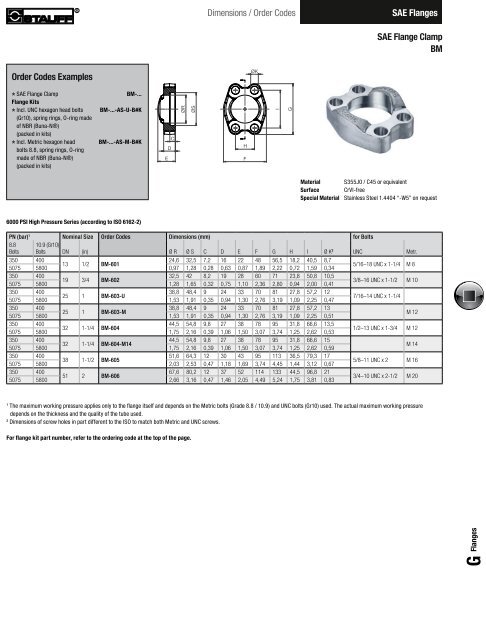
<strong>SAE</strong> <strong>Flange</strong> <strong>Clamp</strong><br />
<strong>BM</strong><br />
Order Codes Examples<br />
**<br />
**<br />
<strong>SAE</strong> <strong>Flange</strong> <strong>Clamp</strong> <strong>BM</strong>-...<br />
<strong>Flange</strong> Kits<br />
Incl. UNC hexagon head bolts <strong>BM</strong>-...-AS-U-B#K<br />
(Gr10), spring rings, O-ring made<br />
of NBR (Buna-N®)<br />
(packed in kits)<br />
**<br />
Incl. Metric hexagon head <strong>BM</strong>-...-AS-M-B#K<br />
bolts 8.8, spring rings, O-ring<br />
made of NBR (Buna-N®)<br />
(packed in kits)<br />
Material<br />
Surface<br />
Special Material<br />
S355J0 / C45 or equivalent<br />
CrVI-free<br />
Stainless Steel 1.4404 “-W5” on request<br />
6000 PSI High Pressure Series (according to ISO 6162-2)<br />
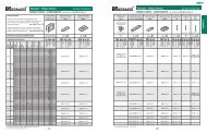
PN (bar) 1 Nominal Size Order Codes Dimensions (mm) for Bolts<br />
8.8<br />
Bolts<br />
10.9 (Gr10)<br />
Bolts DN (in) Ø R Ø S C D E F G H I Ø K 2 UNC Metr.<br />
350 400<br />
24,6 32,5 7,2 16 22 48 56,5 18,2 40,5 8,7<br />
13 1/2 <strong>BM</strong>-601<br />
5075 5800 0,97 1,28 0,28 0,63 0,87 1,89 2,22 0,72 1,59 0,34<br />
5/16–18 UNC x 1-1/4 M 8<br />
350 400<br />
32,5 42 8,2 19 28 60 71 23,8 50,8 10,5<br />
19 3/4 <strong>BM</strong>-602<br />
5075 5800 1,28 1,65 0,32 0,75 1,10 2,36 2,80 0,94 2,00 0,41<br />
3/8–16 UNC x 1-1/2 M 10<br />
350 400<br />
38,8 48,4 9 24 33 70 81 27,8 57,2 12<br />
25 1 <strong>BM</strong>-603-U<br />
5075 5800 1,53 1,91 0,35 0,94 1,30 2,76 3,19 1,09 2,25 0,47<br />
7/16–14 UNC x 1-1/4<br />
350 400<br />
38,8 48,4 9 24 33 70 81 27,8 57,2 13<br />
25 1 <strong>BM</strong>-603-M<br />
5075 5800 1,53 1,91 0,35 0,94 1,30 2,76 3,19 1,09 2,25 0,51<br />
M 12<br />
350 400<br />
44,5 54,8 9,8 27 38 78 95 31,8 66,6 13,5<br />
32 1-1/4 <strong>BM</strong>-604<br />
5075 5800 1,75 2,16 0,39 1,06 1,50 3,07 3,74 1,25 2,62 0,53<br />
1/2–13 UNC x 1-3/4 M 12<br />
350 400<br />
44,5 54,8 9,8 27 38 78 95 31,8 66,6 15<br />
32 1-1/4 <strong>BM</strong>-604-M14<br />
5075 5800 1,75 2,16 0,39 1,06 1,50 3,07 3,74 1,25 2,62 0,59<br />
M 14<br />
350 400<br />
51,6 64,3 12 30 43 95 113 36,5 79,3 17<br />
38 1-1/2 <strong>BM</strong>-605<br />
5075 5800 2,03 2,53 0,47 1,18 1,69 3,74 4,45 1,44 3,12 0,67<br />
5/8–11 UNC x 2 M 16<br />
350 400<br />
67,6 80,2 12 37 52 114 133 44,5 96,8 21<br />
51 2 <strong>BM</strong>-606<br />
5075 5800 2,66 3,16 0,47 1,46 2,05 4,49 5,24 1,75 3,81 0,83<br />
3/4–10 UNC x 2-1/2 M 20<br />
1<br />
The maximum working pressure applies only to the flange itself and depends on the Metric bolts (Grade 8.8 / 10.9) and UNC bolts (Gr10) used. The actual maximum working pressure<br />
depends on the thickness and the quality of the tube used.<br />
2<br />
Dimensions of screw holes in part different to the ISO to match both Metric and UNC screws.<br />
For flange kit part number, refer to the ordering code at the top of the page.<br />
G <strong>Flange</strong>s<br />
www.stauff.com<br />
G7