Trus Joist Framers Handbook.pdf
Trus Joist Framers Handbook.pdf
Trus Joist Framers Handbook.pdf

You also want an ePaper? Increase the reach of your titles
YUMPU automatically turns print PDFs into web optimized ePapers that Google loves.
<strong>Trus</strong> <strong>Joist</strong> ®<br />
TJI ® 110<br />
TJI ® 210<br />
TJI ® 230<br />
TJI ® 360<br />
TJI ® 560<br />
<strong>Joist</strong>s<br />
December 2007<br />
■<br />
Reorder TJ-9001<br />
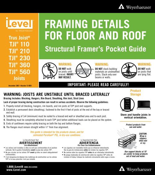
FRAMING DETAILS<br />
FOR FLOOR AND ROOF<br />
Structural Framer’s Pocket Guide<br />
WARNING: JOISTS ARE UNSTABLE UNTIL BRACED LATERALLY<br />
Bracing Includes: Blocking, Hangers, Rim Board, Sheathing, Rim <strong>Joist</strong>, Strut Lines<br />
Lack of proper bracing during construction can result in serious accidents. Observe the following guidelines:<br />
1. Properly install all blocking, hangers, rim boards, and rim joists at TJI ® joist end supports.<br />
2. Establish a permanent deck (sheathing), fastened to the first 4 feet of joists at the end of the bay or braced<br />
end wall.<br />
3. Safety bracing of 1x4 (minimum) must be nailed to a braced end wall or sheathed area and to each joist.<br />
4. Sheathing must be completely attached to each TJI ® joist before additional loads can be placed on the system.<br />
5. Ends of cantilevers require safety bracing on both the top and bottom flanges.<br />
6. The flanges must remain straight within 1 ⁄2" from true alignment.<br />
La Sécurité Avant Tout<br />
AVERTISSEMENT<br />
Lire Attentivement<br />
■<br />
Les solives sont instables si elles ne sont pas contreventées et en position<br />
verticale. Voir le guide d’installation avant la pose des solives TJI ® .<br />
■ Ne pas circuler sur les solives TJI® avant qu’elles ne soient adéquatement<br />
contreventées.<br />
■<br />
Il est dangereux de déposer des matériaux de construction sur les solives<br />
TJI ® si le sous-plancher n’est pas installé.<br />
WARNING:<br />
DO NOT walk<br />
on joists until<br />
braced. INJURY<br />
MAY RESULT.<br />
This guide is intended for the products shown, and for<br />
untreated Parallam ® PSL, in dry-use conditions.<br />
WARNING:<br />
DO NOT stack building<br />
materials on unsheathed<br />
joists. Stack only over<br />
beams or walls.<br />
IMPORTANT: PLEASE READ CAREFULLY!<br />
La Seguridad Ante Todo<br />
ADVERTENCIA<br />
Por Favor Lea Cuidadosamente<br />
■<br />
Las viguetas son inestables hasta que se refuercen lateralmente.<br />
Vea la guía de instalaciones antes de instalar las viguetas TJI ® .<br />
■ No camine sobre las viguetas TJI® antes de ser reforzadas lateralmente.<br />
■<br />
No ponga materiales de construcción sobre las viguetas TJI ® antes de<br />
instalar el triplay. Coloque los materials únicamente sobre vigas o muros.<br />
Product<br />
Storage<br />
WARNING:<br />
DO NOT walk<br />
on joists that<br />
are lying flat.<br />
Store and handle joists in<br />
vertical orientation.<br />
Protect products from<br />
sun and water.<br />
CAUTION:<br />
Wrap is<br />
slippery<br />
when wet<br />
or icy.<br />
Use support blocks at 10'<br />
on-center to keep products<br />
out of mud and water.<br />
1.888.iLevel8 (888.453.8358)<br />
www.iLevel.com
CONTENTS<br />
Floor<br />
Allowable Holes —<br />
iLevel ® <strong>Trus</strong> <strong>Joist</strong> ® TJI ® <strong>Joist</strong>s ......... 1<br />
TJI ® <strong>Joist</strong> Nailing<br />
Requirements at Bearing ............ 2<br />
iLevel ® <strong>Trus</strong> <strong>Joist</strong> ® FrameWorks ® Floor . . 2<br />
iLevel ® <strong>Trus</strong> <strong>Joist</strong> ® Silent Floor ® <strong>Joist</strong><br />
Framing ......................... 3<br />
Fastening of Floor Panels ............ 3<br />
Rim Board Details and Installation ..... 4<br />
Floor Details ................... 4–5<br />
Cantilever Details ................. 5<br />
Filler and Backer Blocks ............ 5<br />
Web Stiffeners .................... 6<br />
Framing Connectors ................ 8<br />
Roof and Wall<br />
Allowable Holes —<br />
iLevel ® <strong>Trus</strong> <strong>Joist</strong> ® TimberStrand ® LSL<br />
Wall Studs. . . . . . . . . . . . . . . . . . . . . . . 2<br />
Web Stiffeners .................... 6<br />
Typical Roof and Wall Framing ........ 6<br />
Ceiling <strong>Joist</strong>s ..................... 6<br />
Roof Details ...................... 7<br />
Framing Connectors ................ 8<br />
Shear Blocking and Ventilation Holes ... 8<br />
TJI ® <strong>Joist</strong> Nailing<br />
Requirements at Bearing ............ 8<br />
1<br />
Beam and Column<br />
Allowable Holes —<br />
iLevel ® <strong>Trus</strong> <strong>Joist</strong> ® TimberStrand ® LSL,<br />
Parallam ® PSL, Microllam ® LVL<br />
Headers and Beams ................ 2<br />
Beam and Column Details ........... 9<br />
Beam and Header Bearings .......... 9<br />
Build Safely<br />
We at iLevel are committed to working safely and want to remind you to<br />
do the same.<br />
We encourage you to follow the recommendations of OSHA (www.osha.gov)<br />
in the U.S. or provincial regulations (www.canoshweb.org/en/) in Canada<br />
regarding:<br />
– Personal protective equipment (PPE) for hands, feet, head, and eyes<br />
– Fall protection<br />
– Use of pneumatic nailers and other hand tools<br />
– Forklift safety<br />
Please adhere to the iLevel product installation details, including the<br />
installation of safety bracing on unsheathed floors and roofs.<br />
PRODUCT IDENTIFICATION<br />
1 3 ⁄4"<br />
2 1 ⁄16" 2 5 ⁄16" 2 5 ⁄16" 3 1 ⁄2"<br />
1 1 ⁄4"–1 3 ⁄8" 1 1 ⁄4"–1 3 ⁄8" 1 1 ⁄4"–1 3 ⁄8" 1 3 ⁄8" 1 3 ⁄8"<br />
9<br />
9<br />
3⁄8" 1 ⁄2"<br />
1 ⁄2"<br />
9 1 ⁄2"<br />
9 1 ⁄2"<br />
11<br />
11 7 ⁄8"<br />
3⁄8" 7 ⁄8"<br />
3<br />
11<br />
⁄8" 7 ⁄8"<br />
11 3⁄8" 7 ⁄8"<br />
7<br />
14"<br />
⁄16"<br />
14"<br />
14"<br />
14"<br />
16"<br />
16"<br />
16"<br />
11 7 ⁄8"<br />
14"<br />
16"<br />
TJI ® 110 joists TJI ® 210 joists TJI ® 230 joists TJI ® 360 joists TJI ® 560 joists<br />
ALLOWABLE HOLES—TJI ® JOISTS Does not apply to vented TJI ® joists<br />
Min. distance from Table A<br />
6"<br />
Do not cut holes larger than<br />
1 1 /2" in cantilever<br />
Min. distance from Table B<br />
6"<br />
1 1 ⁄2" hole<br />
may be cut<br />
anywhere in<br />
web outside of<br />
hatched zone<br />
DO NOT cut holes<br />
in cantilever<br />
reinforcement.<br />
6"<br />
No field<br />
cut holes<br />
in hatched<br />
zone<br />
L 1 2 x D 1 D 1<br />
minimum<br />
(applies to all<br />
holes except<br />
knockouts)<br />
L 2<br />
2 x L 2<br />
minimum<br />
D 2<br />
6"<br />
No field<br />
cut holes<br />
in hatched<br />
zone<br />
6"<br />
DO NOT cut or<br />
notch flange.
Table A—End Support<br />
Minimum distance from edge of hole to inside face of nearest end support<br />
<strong>Joist</strong><br />
Depth<br />
9 1 ⁄2"<br />
11 7 ⁄8"<br />
14"<br />
16"<br />
Round Hole Size Square or Rectangular Hole Size<br />
TJI ® 2" 3" 4" 6 1 ⁄2" 8 7 ⁄8" 11" 13" 2" 3" 4" 6 1 ⁄2" 8 7 ⁄8" 11" 13"<br />
110 1'-0" 1'-6" 2'-0" 5'-0" 1'-0" 1'-6" 2'-6" 4'-6"<br />
210 1'-0" 1'-6" 2'-0" 5'-0" 1'-0" 2'-0" 2'-6" 5'-0"<br />
230 1'-0" 2'-0" 2'-6" 5'-6" 1'-0" 2'-0" 3'-0" 5'-0"<br />
360 1'-6" 2'-0" 3'-0" 6'-0" 1'-6" 2'-6" 3'-6" 5'-6"<br />
110 1'-0" 1'-0" 1'-0" 2'-6" 5'-0" 1'-0" 1'-0" 1'-6" 4'-6" 6'-0"<br />
210 1'-0" 1'-0" 1'-0" 2'-6" 5'-6" 1'-0" 1'-0" 2'-0" 5'-0" 6'-6"<br />
230 1'-0" 1'-0" 1'-0" 3'-0" 6'-0" 1'-0" 1'-0" 2'-0" 5'-6" 7'-0"<br />
360 1'-0" 1'-0" 1'-6" 4'-6" 7'-0" 1'-0" 1'-0" 2'-6" 6'-6" 7'-6"<br />
560 1'-0" 1'-0" 1'-6" 5'-0" 8'-0" 1'-0" 2'-0" 3'-6" 7'-0" 8'-0"<br />
110 1'-0" 1'-0" 1'-0" 1'-0" 2'-6" 5'-0" 1'-0" 1'-0" 1'-0" 3'-6" 6'-0" 8'-0"<br />
210 1'-0" 1'-0" 1'-0" 1'-0" 3'-0" 6'-0" 1'-0" 1'-0" 1'-0" 4'-0" 6'-6" 8'-6"<br />
230 1'-0" 1'-0" 1'-0" 1'-6" 3'-6" 6'-6" 1'-0" 1'-0" 1'-0" 4'-0" 7'-0" 9'-0"<br />
360 1'-0" 1'-0" 1'-0" 2'-6" 5'-6" 8'-0" 1'-0" 1'-0" 1'-0" 5'-6" 8'-0" 9'-6"<br />
560 1'-0" 1'-0" 1'-0" 2'-6" 6'-0" 9'-0" 1'-0" 1'-0" 1'-6" 6'-6" 9'-0" 10'-0"<br />
210 1'-0" 1'-0" 1'-0" 1'-0" 1'-6" 3'-6" 6'-0" 1'-0" 1'-0" 1'-0" 2'-6" 6'-6" 8'-0" 10'-6"<br />
230 1'-0" 1'-0" 1'-0" 1'-0" 2'-0" 4'-0" 6'-6" 1'-0" 1'-0" 1'-0" 3'-0" 7'-0" 9'-0" 11'-0"<br />
360 1'-0" 1'-0" 1'-0" 1'-0" 3'-0" 6'-0" 9'-0" 1'-0" 1'-0" 1'-0" 4'-0" 9'-0" 10'-0" 11'-6"<br />
560 1'-0" 1'-0" 1'-0" 1'-0" 3'-0" 6'-6" 10'-0" 1'-0" 1'-0" 1'-0" 5'-0" 10'-0" 11'-0" 12'-0"<br />
Table B—Intermediate or Cantilever Support<br />
Minimum distance from edge of hole to inside face of nearest intermediate or cantilever support<br />
<strong>Joist</strong><br />
Round Hole Size Square or Rectangular Hole Size<br />
TJI<br />
Depth<br />
2" 3" 4" 6 1 ⁄2" 8 7 ⁄8" 11" 13" 2" 3" 4" 6 1 ⁄2" 8 7 ⁄8" 11" 13"<br />
110 1'-6" 2'-6" 3'-0" 7'-6" 1'-6" 2'-6" 3'-6" 6'-6"<br />
9 1 ⁄2"<br />
210 2'-0" 2'-6" 3'-6" 7'-6" 2'-0" 3'-0" 4'-0" 7'-0"<br />
230 2'-6" 3'-0" 4'-0" 8'-0" 2'-6" 3'-0" 4'-6" 7'-6"<br />
360 3'-0" 4'-0" 5'-6" 9'-0" 3'-0" 4'-6" 5'-6" 8'-0"<br />
110 1'-0" 1'-0" 1'-6" 4'-0" 8'-0" 1'-0" 1'-6" 2'-6" 6'-6" 9'-0"<br />
210 1'-0" 1'-0" 2'-0" 4'-6" 9'-0" 1'-0" 2'-0" 3'-0" 7'-6" 10'-0"<br />
11 7 ⁄8" 230 1'-0" 2'-0" 2'-6" 5'-0" 9'-6" 1'-0" 2'-6" 3'-6" 8'-0" 10'-0"<br />
360 2'-0" 3'-0" 4'-0" 7'-0" 11'-0" 2'-0" 3'-6" 5'-0" 9'-6" 11'-0"<br />
560 1'-6" 3'-0" 4'-6" 8'-0" 12'-0" 3'-0" 4'-6" 6'-0" 10'-6" 12'-0"<br />
110 1'-0" 1'-0" 1'-0" 2'-0" 4'-6" 8'-0" 1'-0" 1'-0" 1'-0" 5'-0" 9'-0" 12'-0"<br />
210 1'-0" 1'-0" 1'-0" 2'-6" 5'-0" 9'-0" 1'-0" 1'-0" 2'-0" 6'-0" 10'-0" 12'-6"<br />
14" 230 1'-0" 1'-0" 1'-0" 3'-0" 5'-6" 10'-0" 1'-0" 1'-0" 2'-6" 6'-0" 10'-6" 13'-0"<br />
360 1'-0" 1'-0" 2'-0" 5'-6" 8'-6" 12'-6" 1'-0" 2'-0" 4'-0" 9'-0" 12'-0" 14'-0"<br />
560 1'-0" 1'-0" 1'-6" 5'-6" 9'-6" 13'-6" 1'-0" 3'-0" 5'-0" 10'-0" 13'-6" 15'-0"<br />
210 1'-0" 1'-0" 1'-0" 1'-0" 3'-0" 5'-6" 9'-6" 1'-0" 1'-0" 1'-0" 4'-6" 9'-6" 12'-6" 15'-6"<br />
16"<br />
230 1'-0" 1'-0" 1'-0" 1'-6" 4'-0" 6'-6" 10'-6" 1'-0" 1'-0" 1'-0" 5'-0" 10'-6" 13'-0" 16'-0"<br />
360 1'-0" 1'-0" 1'-0" 3'-0" 6'-6" 10'-0" 13'-6" 1'-0" 1'-0" 2'-0" 7'-6" 13'-0" 14'-6" 17'-0"<br />
560 1'-0" 1'-0" 1'-0" 2'-6" 7'-0" 11'-0" 15'-0" 1'-0" 1'-0" 3'-6" 9'-0" 14'-6" 16'-0" 18'-0"<br />
■<br />
Leave 1 ⁄8" of web (minimum) at top and bottom of hole. DO NOT cut joist flanges.<br />
■<br />
Tables are based on uniform load tables in current design literature.<br />
■<br />
For simple span (5' minimum), uniformly loaded joists used in residential applications, one maximum size round hole may be<br />
located at the center of the joist span provided that no other holes occur in the joist.
ALLOWABLE HOLES<br />
2<br />
1.55E TimberStrand ® LSL Headers and Beams<br />
1⁄3 depth<br />
2 x diameter of the largest hole (minimum)<br />
Allowed hole zone<br />
GENERAL NOTES<br />
■<br />
Round holes only.<br />
Other iLevel ® <strong>Trus</strong> <strong>Joist</strong> ® Headers and Beams<br />
1.3E<br />
TimberStrand ® LSL<br />
hole zone<br />
8" 8"<br />
■<br />
No holes in headers or beams in plank orientation.<br />
Microllam ® LVL and<br />
Parallam ® PSL hole zone<br />
2 x diameter of<br />
the largest hole<br />
(minimum)<br />
1 ⁄3 depth<br />
■<br />
Header and<br />
Beam<br />
Depth<br />
Maximum<br />
Round Hole<br />
Size<br />
91⁄4"–91⁄2" 3"<br />
111⁄4"–11 7 ⁄8" 3 5 ⁄8"<br />
14"–16" 4 5 ⁄8"<br />
<br />
See illustration for<br />
allowed hole zone.<br />
DO NOT cut, notch, or drill<br />
holes in headers or beams<br />
except as indicated in the<br />
illustrations and tables.<br />
d<br />
d<br />
Microllam ® LVL and<br />
Parallam ® PSL<br />
allowed hole zone<br />
middle 1 ⁄3 span<br />
1.3E TimberStrand ® LSL allowed hole zone<br />
d<br />
■<br />
Header and<br />
Beam<br />
Depth<br />
Maximum<br />
Round Hole<br />
Size<br />
4 3 ⁄8" 1"<br />
51⁄2" 1 3 ⁄4"<br />
71⁄4"–20" 2"<br />
<br />
See illustration for<br />
allowed hole zone.<br />
GENERAL NOTES<br />
■<br />
Allowed hole zone suitable for uniformly<br />
loaded headers and beams only.<br />
■<br />
Round holes only.<br />
TimberStrand ® LSL Wall Studs<br />
■<br />
No holes in cantilevers.<br />
■<br />
No holes in headers or beams in plank<br />
orientation.<br />
The notch shown may be cut anywhere except the middle 1 ⁄3 of the length of the stud.<br />
One hole may be drilled anywhere along the length of the stud or column but must be at least 5 ⁄8" from the edge.<br />
5⁄8" minimum edge distance Maximum notch:<br />
7⁄8" for 3 1 ⁄2" thick walls<br />
Maximum diameter:<br />
1 3 ⁄8" for 3 1 ⁄2" thick walls<br />
2 3 ⁄16" for 5 1 ⁄2"–11 1 ⁄4" thick walls<br />
1 3 ⁄8" for 5 1 ⁄2"–11 1 ⁄4" thick walls<br />
DO NOT cut a notch<br />
and a hole in the<br />
same cross section.
TJI ® JOIST NAILING REQUIREMENTS AT BEARING<br />
TJI ® <strong>Joist</strong> to Bearing Plate<br />
1 1 ⁄4" TimberStrand ® LSL or iLevel ® 1 1 ⁄8" rim board<br />
One 8d (2 1 ⁄2") box<br />
nail each side.<br />
Drive nails at an<br />
angle at least 1 1 ⁄2"<br />
from end.<br />
1 3 ⁄4" minimum end bearing for<br />
single-family applications<br />
■<br />
Increased bearing capacities<br />
may be achieved with increased<br />
bearing lengths. See plans for<br />
required bearing lengths.<br />
3 1 ⁄2" minimum<br />
intermediate bearing<br />
5 1 ⁄4" may be required for<br />
maximum capacity<br />
Shear transfer: Connections equivalent to floor panel nailing schedule.<br />
See page 4.<br />
1 3 ⁄4" minimum<br />
bearing<br />
Rim to TJI ® <strong>Joist</strong><br />
1 1 ⁄4" TimberStrand ® LSL rim board,<br />
iLevel ® 1 1 ⁄8" rim board, or TJI ® 110 rim joist:<br />
One 10d (3") box nail into each flange<br />
TJI ® 210, 230, and 360 rim joist:<br />
One 16d (3 1 ⁄2") box nail into each flange<br />
FRAMEWORKS ® FLOOR SYSTEM<br />
Locate rim board joint between joists<br />
Squash Blocks to TJI ® <strong>Joist</strong><br />
(Load bearing wall above)<br />
One 10d (3") box nail<br />
into each flange<br />
TJI ® 560 rim joist:<br />
Toenail with 10d (3") box<br />
nails, one each side of TJI ®<br />
joist flange<br />
Top View<br />
Also see detail B2,<br />
page 5<br />
TJI ® 560 floor joist<br />
TJI ® 560 rim joist<br />
FrameWorks ® FLOOR SYSTEM COMPONENTS<br />
■<br />
TJ-Performance Plus ® floor panels<br />
■<br />
TJI ® joists<br />
■<br />
1 1 ⁄4" TimberStrand ® LSL or iLevel ® 1 1 ⁄8" rim board<br />
ADHESIVE RECOMMENDATIONS<br />
■<br />
Adhesives must meet the requirements of<br />
ASTM D3498 (AFG-01), and they must have a<br />
minimum dry shear strength of 350 psi. For more<br />
information, contact your iLevel representative.<br />
Nail panel to joist at 12" on-center in field and 6" on-center along<br />
panel edges. Apply fasteners 3 ⁄8" from panel edges.<br />
■<br />
For 3 ⁄4" panels, use 8d (2 1 ⁄2") common or 6d (2") deformed-shank<br />
nails or other code-approved fasteners.<br />
■<br />
For 7 ⁄8" panels, use 8d (2 1 ⁄2") common or 8d (2 1 ⁄2")<br />
deformed-shank nails or other code-approved fasteners.<br />
Apply a 1 ⁄4" or larger bead of adhesive<br />
At abutting panel edges, apply two 1 ⁄4" beads of adhesive<br />
■<br />
Fully nail floor panel within 10 minutes of applying adhesive (or<br />
sooner if required by adhesive manufacturer).<br />
■<br />
Screws may be substituted for the nails noted above if the<br />
screws have equivalent lateral load capacity.
SILENT FLOOR ® JOIST FRAMING<br />
3<br />
Silent Floor ® joist framing does not require<br />
bridging or mid-span blocking<br />
End of joists at<br />
centerline of<br />
support<br />
Protect untreated<br />
wood from direct<br />
contact with<br />
concrete<br />
Use only engineered<br />
lumber for rim board<br />
or blocking.<br />
1 1 ⁄2" knockouts<br />
at approximately<br />
12" on-center<br />
Bearing plate to be flush with<br />
inside face of wall or beam<br />
See Filler and Backer<br />
Blocks on page 5<br />
See<br />
Allowable Holes<br />
on page 1<br />
Blocking<br />
panel<br />
Safety bracing (1x4 minimum)<br />
at 8' on-center (6' on-center for<br />
TJI ® 110 joists) and extended<br />
to a braced end wall. Fasten at<br />
each joist with two 8d (2 1 ⁄2") nails<br />
minimum (see Warning on cover).<br />
E2<br />
Rim board joint<br />
A1<br />
between joists<br />
TJI ®<br />
rim joist 1 1 ⁄4"<br />
A3_ TimberStrand ® LSL<br />
or iLevel ® 1 1 ⁄8"<br />
CS<br />
rim board<br />
A2<br />
L3<br />
B1<br />
L5<br />
B2<br />
H1<br />
L1<br />
B3<br />
L4<br />
P<br />
H1<br />
B4<br />
H2<br />
Use B1 or B2 at<br />
intermediate bearings<br />
with load bearing or<br />
shear wall from above<br />
H3<br />
Structural<br />
sheathing<br />
E1<br />
LA<br />
See Exterior Deck<br />
Attachment on page 4<br />
WARNING<br />
<strong>Joist</strong>s are unstable until<br />
laterally braced.<br />
See Warning on cover.<br />
INSTALLATION TIPS<br />
■<br />
Subfloor adhesive will improve floor performance, but may<br />
not be required.<br />
■<br />
Squash blocks and blocking panels carry stacked vertical<br />
loads (details B1 and B2). Packing out the web of a TJI ®<br />
joist (with web stiffeners) is not a substitute for squash<br />
blocks or blocking panels.<br />
Shifted joist<br />
Plumbing drop<br />
Additional joist<br />
■<br />
When joists are doubled at non-load bearing parallel<br />
partitions, space joists apart the width of the wall for<br />
plumbing or HVAC.<br />
■<br />
Additional joist at plumbing drop (see detail above).
End bearings (see page 4)<br />
A1<br />
A2<br />
A3<br />
with blocking panels<br />
with TJI ® rim joist<br />
with rim board<br />
Intermediate bearings* (see page 5)<br />
B1<br />
B2<br />
B3<br />
with blocking panels to support load bearing wall above<br />
with squash blocks to support load bearing wall above<br />
without blocking panels or squash blocks (no wall above)<br />
Cantilever details (see page 5)<br />
E1<br />
E1W<br />
E2<br />
E3<br />
E4<br />
F1<br />
PB1<br />
no reinforcement<br />
no reinforcement, with web stiffener<br />
3 ⁄4" reinforcement on one side<br />
3 ⁄4" reinforcement both sides<br />
joist reinforcement<br />
deck cantilever<br />
permanent bracing<br />
Guidelines for Closest On-Center Spacing per Row<br />
DETAIL SCHEDULE<br />
Cantilever over brick ledge (see page 5)<br />
3 ⁄4" reinforcement on one side, with vertical blocking<br />
3 ⁄4" reinforcement both sides, with vertical blocking<br />
3 ⁄4" reinforcement on one side, with horizontal blocking<br />
3 ⁄4" reinforcement on both sides, with horizontal blocking<br />
Hanger details (more connector information on page 8)<br />
TJI ® joist to beam (see page 8)<br />
TJI ® joist to joist (see page 5)<br />
TJI ® joist on masonry wall or steel beam (see page 8)<br />
Other details<br />
B4 butting joists with blocking panels (see above)<br />
CS column support (see page 4)<br />
LA exterior deck attachment (see page 4)<br />
W web stiffeners (see page 6)<br />
L beam details (see page 9)<br />
P column details (see page 9)<br />
*Load bearing wall must stack over wall below. Blocking panels may be required at shear walls above or below.<br />
iLevel ® TJ-Xpert ® SOFTWARE FRAMING PLANS<br />
B_W Web stiffeners required on each side of joist at intermediate bearings. Refer to your TJ-Xpert ® framing plan.<br />
Bearing requirements as shown on the TJ-Xpert ® framing plan are job-specific and supersede minimum bearing requirements listed.<br />
FASTENING OF FLOOR PANELS<br />
Nail Size<br />
110, 210,<br />
and 230<br />
TJI ®(1) Rim board 1 1 ⁄2"<br />
360 and iLevel ® 1 1 ⁄4"<br />
560 1 1 ⁄8" TimberStrand ® LSL<br />
TimberStrand ® LSL<br />
or wider<br />
Microllam ®<br />
LVL<br />
8d (0.131" x 2 1 ⁄2") common 4" 3" 6" 4" 3" 3" 3"<br />
10d (0.148" x 3"), 12d (0.148" x 3 1 ⁄4") common 4" 4" 6" 4" 4" 4" 4"<br />
16d (0.162" x 3 1 ⁄2") common 6" 6" 16" 6" (2) 6" (2) 8" 6"<br />
Parallam ®<br />
PSL<br />
(1) One row of fasteners permitted (two at abutting panel edges) for diaphragms. Stagger nails when using 4" on-center spacing and maintain 3 ⁄8"<br />
joist and panel edge distance. For other applications, multiple rows of fasteners are permitted if the rows are offset at least 1 ⁄2" and staggered.<br />
(2) Can be reduced to 4" on-center with maximum nail penetration of 1 3 ⁄8" into the narrow edge.<br />
E5<br />
E6<br />
E7<br />
E8<br />
H1<br />
H2<br />
H3<br />
■<br />
Recommended nailing is 12" on-center in field and 6" on-center<br />
along panel edge. Fastening requirements on engineered drawings<br />
supersede recommendations listed above.<br />
■<br />
iLevel recommends using a non-polyurethane subfloor adhesive on<br />
all contact points between panels and floor framing.<br />
■<br />
Nailing rows must be offset at least 1 ⁄2" and staggered.<br />
■<br />
14 ga. staples may be substituted for 8d (2 1 ⁄2") nails<br />
if minimum penetration of 1" into the TJI ® joist or rim<br />
board is achieved.<br />
■<br />
Maximum spacing of nails is 18" on-center for<br />
TJI ® joists.
RIM BOARD DETAILS AND INSTALLATION<br />
4<br />
Plate nail<br />
Floor panel nail<br />
Rim board to TJI ® joist<br />
1 1 ⁄4" TimberStrand ® LSL<br />
or iLevel ® 1 1 ⁄8" rim board<br />
(see nailing schedule below)<br />
Toe nail<br />
Rim board to TJI ® joist<br />
Sheathing may<br />
be attached as<br />
shown in A3.4<br />
2x4 or 2x6 stud wall<br />
at 16" on-center<br />
When<br />
sheathing<br />
thickness<br />
exceeds 7 ⁄8",<br />
trim sheathing<br />
tongue at<br />
rim board<br />
Plate nail<br />
Floor panel nail<br />
Rim board to TJI ® joist<br />
1 1 ⁄4" TimberStrand ® LSL<br />
rim board<br />
Attach panel per nailing<br />
schedule (below)<br />
Toe nail<br />
Rim board to TJI ® joist<br />
2x4 or 2x6 stud wall<br />
at 16" on-center<br />
When<br />
sheathing<br />
thickness<br />
exceeds 7 ⁄8",<br />
trim sheathing<br />
tongue at<br />
rim board<br />
TJI ® joist spanning<br />
in either direction<br />
12" minimum<br />
Install proper<br />
TJI ® joist spanning<br />
in either direction<br />
TJI ® joist to plate<br />
blocking to support<br />
all panel edges<br />
TJI ® joist to plate<br />
A3.1 A3.2 A3.3 A3.4<br />
Wall Framing<br />
Specifications<br />
Rim Board Installation Detail<br />
A3.1 (1)(2) A3.2 (1)(2) A3.3 (1) A3.4 (1)<br />
Rim Board Thickness 1 1 ⁄8" 11⁄4" 11⁄4" 11⁄4"<br />
Plate Nail—16d (0.135" x 3 1 ⁄2") box 16" o.c. 12" o.c. 8" o.c. 12" o.c.<br />
Floor Panel Nail—8d (0.131" x 2 1 ⁄2") common<br />
6" o.c.<br />
Rim Board to TJI ® <strong>Joist</strong>—10d (0.128" x 3") box<br />
One into each flange<br />
Toe Nail—10d (0.128" x 3") box 6" o.c. 6" o.c. 4" o.c. 6" o.c.<br />
TJI ® <strong>Joist</strong> to Plate—8d (0.113" x 2 1 ⁄2") box Two nails driven at an angle into bottom flange, one each side of web at least 11/2" from end<br />
Exterior Face<br />
Interior<br />
Face<br />
Hold-<br />
Downs<br />
Sheathing<br />
7 ⁄16" structural 1<br />
sheathing (3) 3 ⁄8" structural 1<br />
sheathing in all areas (4)<br />
Boundary Nailing 8d common at 6" o.c. 8d common at 4" o.c.<br />
Per Code<br />
Per Code<br />
Intermediate Nailing 8d common at 12" o.c. 8d common at 12" o.c.<br />
Max. Window Opening Height 5'-4" (5) 5'-4" (5)<br />
% of Wall with Full Height Sheathing 70% 70%<br />
Sheathing<br />
1⁄2" gypsum<br />
1⁄2" gypsum<br />
Boundary Nailing Per Code<br />
Per Code 5d cooler at 7" o.c. 5d cooler at 7" o.c.<br />
Intermediate Nailing 5d cooler at 10" o.c. 5d cooler at 10" o.c.<br />
90 mph Wind Zone none<br />
120 mph Wind Zone<br />
16" o.c. within 10' 16" o.c. within 6' 16" o.c. within 4'<br />
of corners (6) of corners (6) of corners (6)<br />
(1) All sheathing shall be properly blocked and nailed.<br />
(2) Verify the lateral capacity of the wall. Not all types of code-allowed wall construction provide the same lateral resistance. Check with<br />
your local building official or design professional.<br />
(3) Detail A3.3 shall be a segmented wall, location of full-height structural sheathing per code.<br />
(4) Sheathing shall be continuous over all plate-to-plate and plate-to-rim-board interfaces and may butt together at mid-depth of rim<br />
board as shown in A3.4. At foundation, fasten the bottom edge of the sheathing to the sill plate.<br />
(5) In addition, one 6'-8" standard door opening is allowed.<br />
(6) If required, hold-downs shall be Simpson Strong-Tie ® CS20 (or equivalent) straps attached with four 8d common nails at each end.<br />
As an alternative to hold-down straps, wall sheathing may be attached as shown in A3.4. See footnote 4.<br />
none
FLOOR DETAILS<br />
Blocking<br />
panel<br />
TJI ® rim joist<br />
A1<br />
A2<br />
Must have 1 3 ⁄4" minimum joist bearing at ends<br />
Exterior Deck Attachment<br />
Load from above<br />
Structural exterior<br />
sheathing<br />
Flashing<br />
1 1 ⁄4" TimberStrand ® LSL<br />
or iLevel ® 1 1 ⁄8"<br />
rim board<br />
Treated 2x_<br />
ledger<br />
2x4 minimum<br />
squash blocks<br />
1⁄16"<br />
Maintain 2" distance<br />
(minimum) from edge of<br />
ledger to fastener<br />
CS<br />
Use 2x4 minimum squash blocks to transfer load<br />
around TJI ® joist<br />
LA<br />
Corrosion-resistant fasteners required for<br />
wet-service applications
FLOOR DETAILS 5<br />
Load bearing or shear wall above<br />
(must stack over wall below)<br />
Blocking<br />
panel<br />
Intermediate Bearing —<br />
No Load Bearing Wall Above<br />
2x4 minimum<br />
squash blocks<br />
B1<br />
B1W<br />
Web stiffeners required each<br />
side at B1W and B2W<br />
1 ⁄16"<br />
Web stiffeners<br />
required each side<br />
at B3W<br />
B2<br />
B2W<br />
Blocking panels may be required with shear<br />
walls above or below—see detail B1<br />
B3<br />
B3W<br />
Blocking panels may be required with shear<br />
walls above or below—see detail B1<br />
CANTILEVER DETAILS<br />
1 1 ⁄4" TimberStrand ® LSL<br />
or iLevel ® 1 ⁄8" rim<br />
board, typical. Nail<br />
with 10d (3") box<br />
nails, one each at top<br />
and bottom flange.<br />
L/3<br />
8' max., typical<br />
1 1 ⁄4" TimberStrand ® LSL<br />
or iLevel ® 1 ⁄8" rim board<br />
closure, typical<br />
Web stiffeners<br />
required at E1W<br />
E1<br />
E1W<br />
E3<br />
8" diameter maximum hole for 11 7 ⁄8"–16"<br />
deep blocking panels; 6" diameter<br />
maximum for blocking panels 9 1 ⁄2" deep or<br />
shorter than 12" long. Do not cut flanges.<br />
E2<br />
4'-0" length of 3 ⁄4"<br />
reinforcement (2'-0" maximum<br />
cantilever) on one side at E2,<br />
both sides at E3. Attach to<br />
joist with 8d (2 1 ⁄2") common<br />
nails at 6" on-center.<br />
When reinforcing both<br />
sides, stagger nails.<br />
E4<br />
12" length of 3 ⁄4"<br />
reinforcement on one side<br />
at E5/E7, both sides at<br />
E6/E8. Attach to joist<br />
flanges with one 8d (2 1 ⁄2")<br />
common nail at each<br />
corner.<br />
E5<br />
E6<br />
Blocking panel between each joist.<br />
Full depth vertical blocking at E5 and<br />
E6, horizontal blocking at E7 and E8.<br />
E8<br />
Two 2 1 ⁄2" screws for 2x_<br />
strapping connections<br />
PB1<br />
E7<br />
Wood<br />
backer<br />
Less than 5"<br />
Nail with connections equivalent to<br />
floor panel schedule (E7 and E8)<br />
F1<br />
Nail through 2x_ cantilever, wood<br />
backer, and TJI ® joist web with 2<br />
rows 10d (3") common nails at<br />
6" on-center, clinched. Use<br />
16d (3 1 ⁄2") nails with TJI ® 560<br />
joists. F1 applies to uniformly<br />
loaded joists only.<br />
1 1 ⁄2 times cantilever length Cantilever length<br />
4'-0" maximum<br />
(uniform loads only)<br />
6'-0" length of TJI ® joist reinforcement (2'-0"<br />
maximum cantilever) and filler block at E4. Attach<br />
to joist web with 3 rows 10d (3") common nails at<br />
6" on-center, clinched. Use 4'-0" length with 9 1 ⁄2"<br />
and 11 7 ⁄8" TJI ® joists, and attach to joist web with<br />
2 rows 10d (3") common nails at 6" on-center,<br />
clinched. Not for use with TJI ® 560 joists.<br />
Apply subfloor adhesive to all<br />
contact surfaces<br />
PB1<br />
FILLER AND BACKER BLOCKS<br />
Two 8d (2 1 ⁄2") box nails<br />
or 2 1 ⁄2" screws, typical<br />
Directly applied ceiling<br />
When specified on the layout, one of the above bracing options is required<br />
H2<br />
DOUBLE TJI ® JOIST FILLER BLOCK<br />
Backer block both<br />
sides of web with<br />
single TJI ® joist<br />
■<br />
Single-Family Applications: Attach with ten<br />
10d (3") box nails, clinched. Use ten 16d (3 1 ⁄2")<br />
box nails from each side with TJI ® 560 joists.<br />
■<br />
Multi-Family Applications: Attach with fifteen<br />
10d (3") box nails, clinched. Use fifteen 16d<br />
(3 1 ⁄2") box nails from each side with TJI ® 560<br />
joists.<br />
HANGER BACKER BLOCK<br />
Install tight to top flange (tight to bottom flange with face mount hangers).<br />
■<br />
Single-Family Applications: Attach with ten 10d (3") box nails, clinched<br />
when possible.<br />
■<br />
Multi-Family Applications: Attach with fifteen 10d (3") box nails,<br />
clinched when possible.<br />
■<br />
If necessary, increase filler and backer block height for face mount<br />
hangers and maintain 1 ⁄8" gap at top of joist; see detail W on page 6.<br />
■<br />
Filler and backer block dimensions should accommodate required nailing<br />
without splitting. The suggested minimum length is 24" for filler<br />
and 12" for backer blocks.<br />
HANGER BACKER BLOCK SIZES<br />
■<br />
TJI ® 110 joists: 5 ⁄8" or 3 ⁄4", minimum length 12"<br />
■<br />
TJI ® 210 joists: 3 ⁄4" or 7 ⁄8", minimum length 12"<br />
■<br />
TJI ® 230 and 360 joists: 1" net, minimum length 12"<br />
■<br />
TJI ® 560 joists: 2x_, minimum length 12"<br />
DOUBLE TJI ® JOIST FILLER SIZES<br />
■<br />
TJI ® 110 joists: 2x_, minimum length 24"<br />
■<br />
TJI ® 210 joists: 2x_ + 3 ⁄8" sheathing, minimum length 24"<br />
■<br />
TJI ® 230 and 360 joists: 2x_ + 1 ⁄2" sheathing, minimum length 24"<br />
■<br />
TJI ® 560 joists: Two 2x_, minimum length 24"
WEB STIFFENERS—FLOOR AND ROOF APPLICATIONS<br />
6<br />
1"<br />
(1 1 ⁄2" for<br />
TJI ® 560<br />
joists)<br />
W<br />
Gap:<br />
1⁄8" minimum<br />
2 3 ⁄4" maximum<br />
Three 8d (2 1 ⁄2") box nails,<br />
clinched<br />
(Three 16d (3 1 ⁄2") box nails<br />
for TJI ® 560 joists)<br />
Web stiffener each side.<br />
See sizes below.<br />
Tight fit<br />
WEB STIFFENER REQUIREMENTS<br />
Required at all birdsmouth cuts.<br />
Required at all sloped hangers.<br />
For TJI ® 560 joists, web stiffeners are<br />
required at all hanger locations.<br />
WEB STIFFENER SIZES<br />
■<br />
TJI ® 110 joists: 5 ⁄8" x 2 5 ⁄16" minimum<br />
■<br />
TJI ® 210 joists: 3 ⁄4" x 2 5 ⁄16" minimum<br />
■<br />
TJI ® 230 and 360 joists: 7 ⁄8" x 2 5 ⁄16" minimum<br />
■<br />
TJI ® 560 joists: 2x4<br />
Required if the sides of the hanger<br />
do not extend to laterally support at<br />
least 3 ⁄8" of the TJI ® joist top flange.<br />
Web stiffeners are required at<br />
intermediate bearing locations only<br />
where noted on framing plan.<br />
TYPICAL ROOF AND WALL FRAMING<br />
DETAIL SCHEDULE<br />
Roof details (see page 7)<br />
Other details<br />
R1 on bevel plate<br />
O 2x_ overhang at end wall<br />
R3 with variable slope seat connector<br />
R5 with birdsmouth cut<br />
SB<br />
W<br />
shear blocking (see page 8)<br />
web stiffeners<br />
R7 intermediate bearing<br />
Hanger details (see page 8)<br />
R8 2x4 outrigger and filler with birdsmouth cut H5 slope adjusted hanger<br />
R9 2x4 outrigger without filler<br />
H6 header on slope<br />
R10 2x4 outrigger and filler<br />
R14 ridge detail<br />
<strong>Joist</strong>s must be laterally supported at cantilever and end bearing<br />
by blocking panels, hangers, or direct attachment to a rim board or rim joist.
See Filler and Backer<br />
Blocks, page 5<br />
R14<br />
H5<br />
Safety bracing (1x4 minimum)<br />
at 8' on-center (6' on-center for<br />
TJI ® 110 joists) and extended<br />
to a braced end wall. Fasten at<br />
each joist with two 8d (2 1 ⁄2")<br />
nails minimum (see Warning<br />
on cover).<br />
R10<br />
O<br />
R7<br />
H6<br />
Blocking panels or<br />
shear blocking optional<br />
for joist stability at<br />
intermediate supports<br />
R9<br />
2x4 block for<br />
soffit support<br />
R1<br />
R1<br />
R3<br />
24"<br />
max.<br />
R5<br />
Double joist<br />
may be<br />
required<br />
Notch around<br />
TJI ® joist top<br />
flange<br />
TimberStrand ® LSL blocking:<br />
– 1 row at 10'–18' height<br />
– 2 rows at 18'–22' height<br />
Let-in<br />
bracing<br />
Studs must be<br />
doubled when notched in<br />
middle third of length.<br />
Refer to hole charts for<br />
allowable holes and<br />
notches.<br />
Install cripples<br />
tight to king stud<br />
at each end of<br />
header<br />
Safety bracing.<br />
Lack of proper bracing<br />
can result in serious<br />
accidents.<br />
See<br />
Allowable Holes,<br />
page 1<br />
R10<br />
R8<br />
Lateral bracing<br />
required at<br />
end bearings<br />
Ceiling <strong>Joist</strong>s<br />
24"<br />
maximum<br />
WARNING<br />
<strong>Joist</strong>s are unstable until<br />
laterally braced.<br />
See Warning on cover.<br />
Ceiling joist must be<br />
braced at<br />
18" on-center<br />
Do not bevel cut<br />
joist beyond inside<br />
face of wall
ROOF DETAILS<br />
7<br />
Shear blocking—<br />
1 1 ⁄4" TimberStrand ® LSL<br />
rim board, iLevel 1 1 ⁄8"<br />
rim board, or TJI ® joist<br />
V-cut shear blocking—<br />
1 1 ⁄4" TimberStrand ® LSL<br />
rim board<br />
Beveled bearing<br />
plate required when<br />
slope exceeds 1 ⁄4"<br />
in 12"<br />
Variable slope<br />
seat connector<br />
R1<br />
1⁄3 adjacent span maximum<br />
R3<br />
1⁄3 adjacent span maximum<br />
Intermediate Bearing<br />
Blocking panels or shear blocking may be specified<br />
for joist stability at intermediate supports.<br />
Beveled web stiffeners<br />
on both sides. Cut to<br />
match roof slope.<br />
Web stiffeners<br />
required each side<br />
at R7W<br />
Twist strap and backer block<br />
required at R7S with slopes<br />
greater than 3" per foot.<br />
See Nailing Requirements,<br />
page 8.<br />
TJI ® joist<br />
flange must<br />
bear fully on<br />
plate<br />
2'-0"<br />
maximum<br />
2x4 block for<br />
soffit support<br />
Birdsmouth<br />
cut must not<br />
overhang<br />
inside face<br />
of plate<br />
Beveled<br />
bearing plate<br />
required when<br />
slope exceeds<br />
1⁄4" in 12"<br />
R5<br />
Birdsmouth cut allowed at low end of joist only<br />
R7 R7W R7S
2 rows 8d (2 1 ⁄2")<br />
box nails at<br />
8" on-center<br />
4'-0"<br />
minimum<br />
2x4 one side. Use 2x4<br />
both sides if joist<br />
spacing is greater than<br />
24" on-center.<br />
1 1 ⁄2"<br />
4'-0"<br />
minimum<br />
2x4 one side.<br />
Use 2x6 if joist<br />
spacing is<br />
greater than<br />
24" on-center.<br />
10d (3") box nails at<br />
8" on-center<br />
2'-0"<br />
maximum<br />
Beveled 2x4<br />
block with<br />
beveled web<br />
stiffener on<br />
opposite side<br />
of web<br />
2'-0"<br />
maximum<br />
Beveled web stiffeners<br />
on both sides<br />
Beveled 2x4 block<br />
R8<br />
Birdsmouth cut allowed at low end of joist only<br />
R9<br />
Birdsmouth cut allowed at low end of joist only<br />
2 rows 8d (2 1 ⁄2")<br />
box nails at<br />
8" on-center<br />
4'-0"<br />
minimum<br />
2x4 one side. Use 2x4<br />
both sides if joist<br />
spacing is greater<br />
than 24" on-center<br />
1 1 ⁄2"<br />
LSTA18 (Simpson or USP)<br />
strap with twelve<br />
10d x 1 1 ⁄2" nails<br />
Additional blocking may be<br />
required for shear transfer<br />
Filler<br />
2'-0"<br />
maximum<br />
Beveled<br />
2x4 block<br />
Beveled bearing plate<br />
required when slope<br />
exceeds 1 ⁄4" in 12"<br />
Double beveled bearing<br />
plate when slope exceeds<br />
1⁄4" in 12"<br />
Strap nails:<br />
Leave 2 3 ⁄8"<br />
minimum<br />
end distance,<br />
typical<br />
R10<br />
R14
FRAMING CONNECTORS<br />
8<br />
APPROVED HANGERS<br />
■<br />
The following manufacturers are approved to supply hangers<br />
for iLevel products:<br />
– Simpson Strong-Tie Co., Inc.: 1-800-999-5099<br />
– USP Structural Connectors: 1-800-328-5934<br />
■<br />
Hanger design loads differ by support type and may exceed the<br />
capacity of the support and/or supported member. Contact your<br />
iLevel representative or refer to iLevel ® software.<br />
Top flange<br />
hanger<br />
Face mount<br />
hanger<br />
Hanger height must<br />
be a minimum of 60%<br />
of joist depth<br />
NAILING REQUIREMENTS<br />
■<br />
Fill all round holes with the proper nails. Hanger nails are<br />
usually a heavier gauge because of the higher loads they<br />
need to carry.<br />
■<br />
Unless specified otherwise, full capacity of straps or<br />
connectors can only be achieved if the following nail<br />
penetration is provided:<br />
FACE MOUNT TOP FLANGE<br />
10d x 1 1 ⁄2" 1 1 ⁄2" minimum 1 1 ⁄2" minimum<br />
10d (3") common 1 3 ⁄4" minimum 3" minimum<br />
16d (3 1 ⁄2") common 2" minimum 3 1 ⁄2" minimum<br />
■<br />
Top flange hangers should be fastened to TJI ® joist headers<br />
with 10d x 1 1 ⁄2" nails. Fasten face mount hangers to 3 1 ⁄2" or<br />
wider TJI ® joist headers with 10d (3") common or 16d (3 1 ⁄2")<br />
common nails.<br />
H1<br />
H3<br />
Web stiffeners required if the sides of<br />
the hanger do not laterally support at<br />
least 3 ⁄8" of the TJI ® joist top flange<br />
Flush bearing plate required.<br />
Maximum 1 ⁄4" overhang<br />
permitted at beam.<br />
CONNECTOR INSTALLATION AND SQUEAK PREVENTION TIPS<br />
■<br />
Nails must be completely set.<br />
■<br />
Leave 1 ⁄16" clearance between the member and the support<br />
member or hanger.<br />
■<br />
<strong>Joist</strong> to beam connections require hangers; do not toenail.<br />
■<br />
Seat the supported member tight to the bottom of the hanger.<br />
On Simpson Strong-Tie ® ITT, IUT, and VPA connectors, bend the<br />
bottom flange tabs over and nail to TJI ® joist bottom flange.<br />
■<br />
Reduce squeaks by adding subfloor adhesive to the hanger<br />
seat.<br />
LSTA24 (Simpson or USP) strap<br />
with twelve 10d x 1 1 ⁄2" nails<br />
required at H5S with slopes<br />
greater than 3/12<br />
Additional blocking may be<br />
required for shear transfer<br />
H5 H5S<br />
Strap nails: Leave<br />
2 3 ⁄8" minimum end<br />
distance<br />
Variable slope joist hanger.<br />
Beveled web stiffener<br />
required each side.
Filler block: Attach with<br />
ten 10d (3") box nails, clinched. Use ten<br />
16d (3 1 ⁄2") box nails from each side with<br />
TJI ® 560 joists.<br />
Backer block: Install tight to bottom<br />
flange (tight to top flange with top flange<br />
hangers). Attach with ten 10d (3") box<br />
nails, clinched when possible.<br />
H6 H6S<br />
LSTA18 strap required at H6S with<br />
slopes greater than 3/12<br />
Strap nails: Leave 2 3 ⁄8" minimum end<br />
distance, typical<br />
Variable slope joist hanger. Beveled web<br />
stiffeners required on each side.<br />
SHEAR BLOCKING AND VENTILATION HOLES Roof Only<br />
1 1 ⁄4" TimberStrand ® LSL rim board for shear blocking<br />
(between joists). Field trim to match joist depth at outer<br />
edge of wall or locate on wall to match joist depth.<br />
1⁄3 1⁄3 1⁄3<br />
1⁄2<br />
For TJI ® joists with slopes of 10/12 to 12/12, the vertical<br />
depth at bearing will require 1 1 ⁄4" TimberStrand ® LSL or<br />
iLevel ® 1 1 ⁄8" rim board (for shear blocking) that is one<br />
size deeper than the TJI ® joist.<br />
SB<br />
Maximum allowable V-cut<br />
1⁄2<br />
TJI ® JOIST NAILING REQUIREMENTS AT BEARING<br />
End Bearing<br />
(1 3 ⁄4" minimum bearing required)<br />
TJI ® <strong>Joist</strong> to Bearing Plate<br />
Intermediate Bearing<br />
(3 1 ⁄2" minimum bearing required)<br />
Blocking to<br />
Bearing Plate<br />
8d (2 1 ⁄2") box nail,<br />
one each side, 1 1 ⁄2"<br />
minimum from end<br />
Slopes 3/12 or less:<br />
One 8d (2 1 ⁄2") box nail each side<br />
(see detail R7)<br />
Slopes greater than 3/12:<br />
Two 8d (2 1 ⁄2") box nails each side,<br />
plus a twist strap and backer block<br />
(see detail R7S)<br />
When slope exceeds 1 ⁄4" per foot, a beveled bearing plate, variable slope seat<br />
connector, or birdsmouth cut (at low end of joist only) is required.<br />
1 1 ⁄4" TimberStrand ® LSL or<br />
iLevel ® 1 1 ⁄8" rim board:<br />
Toenail with 10d (3") box nails at<br />
6" on-center or 16d (3 1 ⁄2") box nails at<br />
12" on-center<br />
TJI ® joist blocking:<br />
10d (3") box nails at 6" on-center<br />
Shear transfer nailing:<br />
Use connections equivalent to sheathing<br />
nail schedule
BEAM AND COLUMN DETAILS<br />
9<br />
DETAIL SCHEDULE<br />
Beam and header details<br />
L1<br />
bearing at wood wall<br />
L2<br />
bearing for door or window header<br />
L3<br />
beam to beam connection<br />
L4<br />
bearing at concrete wall<br />
L5<br />
bearing at wood or steel column<br />
L6<br />
connection of multiple pieces<br />
Column details<br />
P1 beam on column cap<br />
P2 column base<br />
P3 elevated column base<br />
Parallam ® PSL or<br />
TimberStrand ® LSL<br />
column with column cap<br />
L5<br />
Parallam ® PSL or<br />
TimberStrand ® LSL<br />
column<br />
P1<br />
Bearing length is extremely critical and must be<br />
considered for each application. See table below for<br />
minimum end and intermediate bearing lengths, and<br />
your iLevel ® TJ-Xpert ® framing plan, if applicable.<br />
L1<br />
Intermediate<br />
support<br />
P2<br />
Rim board or blocking<br />
for lateral support<br />
Cut only round holes and only in the center of<br />
beam (see Allowable Holes, page 2)<br />
Span<br />
If short span is less than 1 ⁄3 of<br />
adjacent span, additional<br />
consideration may be required<br />
L2<br />
L3<br />
This guide is intended<br />
for the products shown,<br />
and for untreated<br />
Parallam ® PSL,<br />
in dry-use conditions<br />
Top flange<br />
hanger<br />
Face mount<br />
hanger<br />
Strap per code if<br />
top plate is not<br />
continuous over<br />
header<br />
L3<br />
P3<br />
Protect<br />
untreated<br />
wood from<br />
direct contact<br />
with concrete<br />
L4<br />
Optional<br />
non-shrink<br />
grout<br />
CONNECTION OF MULTIPLE PIECES OF TOP-LOADED BEAMS (1)<br />
1 3 ⁄4" Wide Pieces<br />
■<br />
Minimum of 3 rows 10d (0.128" x 3") nails at 12" on-center<br />
■<br />
Minimum of 4 rows 10d (0.128" x 3") nails at 12" on-center for 14" and deeper<br />
beams<br />
■<br />
If using 12d–16d common nails, the number of nailing rows can be reduced by one<br />
L6<br />
3 1 ⁄2" Wide Pieces<br />
■<br />
Minimum of 2 rows 1 ⁄2" bolts at 24" on-center, staggered<br />
(1) Load must be applied evenly across entire beam width. Otherwise, use connections for side-loaded beams.<br />
CONNECTION OF MULTIPLE PIECES OF SIDE-LOADED BEAMS<br />
■<br />
Additional nailing or bolting may be required with side-loaded multiple- member<br />
beams. Refer to current product literature.
BEAM AND HEADER BEARINGS<br />
Minimum Bearing Length for Beams and Headers<br />
Beam Depth Bearing<br />
Span of Header or Beam<br />
4' 6' 8' 10' 12' 16' 20' 24' 28'<br />
5 1 ⁄2" End / Int. 2 1 ⁄4" / 4 1 ⁄2" 1 1 ⁄2" / 3 1 ⁄2" 1 1 ⁄2" / 3 1 ⁄2" 1 1 ⁄2" / 3 1 ⁄2" 1 1 ⁄2" / 3 1 ⁄2"<br />
7 1 ⁄4" End / Int. 3 1 ⁄2" / 6 1 ⁄4" 2 1 ⁄4" / 5 1 ⁄2" 1 3 ⁄4" / 4 1 ⁄4" 1 1 ⁄2" / 3 1 ⁄2" 1 1 ⁄2" / 3 1 ⁄2" 1 1 ⁄2" / 3 1 ⁄2"<br />
8 5 ⁄8" End / Int. 3 1 ⁄2" / 8 1 ⁄2" 2 1 ⁄4" / 5 3 ⁄4" 1 3 ⁄4" / 4 1 ⁄4" 1 1 ⁄2" / 3 1 ⁄2" 1 1 ⁄2" / 3 1 ⁄2" 1 1 ⁄2" / 3 1 ⁄2" 1 1 ⁄2" / 3 1 ⁄2" 1 1 ⁄2" / 3 1 ⁄2"<br />
9 1 ⁄4", 9 1 ⁄2" End / Int. 4 1 ⁄4" / 8" 3 1 ⁄4" / 7 1 ⁄2" 2 1 ⁄2" / 6 1 ⁄4" 2" / 5 1 ⁄4" 1 1 ⁄2" / 4" 1 1 ⁄2" / 3 1 ⁄2" 1 1 ⁄2" / 3 1 ⁄2" 1 1 ⁄2" / 3 1 ⁄2"<br />
11 1 ⁄4", 11 7 ⁄8" End / Int. 4" / 9 1 ⁄4" 3 1 ⁄4" / 8" 2 1 ⁄4" / 6" 1 3 ⁄4" / 4 3 ⁄4" 1 1 ⁄2" / 4" 1 1 ⁄2" / 3 1 ⁄2"<br />
14" End / Int. 4 1 ⁄2" / 10 3 ⁄4" 3 1 ⁄4" / 8 1 ⁄4" 2 1 ⁄2" / 6 1 ⁄2" 2" / 5 1 ⁄2" 1 3 ⁄4" / 4 3 ⁄4"<br />
16" End / Int. 4 1 ⁄4" / 10 1 ⁄2" 3 1 ⁄4" / 8 1 ⁄2" 2 3 ⁄4" / 7" 2 1 ⁄4" / 6"<br />
18" End / Int. 4 1 ⁄4" / 10 1 ⁄2" 3 1 ⁄4" / 8 3 ⁄4" 2 3 ⁄4" / 7 1 ⁄2"<br />
20" End / Int. 4 1 ⁄4" / 10 3 ⁄4" 3 1 ⁄2" / 9 1 ⁄4"<br />
■<br />
Bearing across full beam width is required.<br />
■<br />
1 1 ⁄2" minimum bearing length at ends, 3 1 ⁄2" at intermediate supports.<br />
■<br />
Bearing lengths are based on bearing stress for TimberStrand ® LSL,<br />
Parallam ® PSL, or Microllam ® LVL. Lengths may need to be increased if<br />
support member’s allowable bearing stress is less (e.g., flat wood plate).<br />
■<br />
Table assumes maximum allowable uniform load. For other conditions,<br />
contact your iLevel representative.<br />
■<br />
Beams and headers require lateral support at bearing points and along the<br />
top (or compression edge) at 24" on-center or closer.<br />
■<br />
1 3 ⁄4" x 16" and deeper beams and headers are to be used in multiple-<br />
Seat cuts must be within wall.<br />
member units only.<br />
Beam Attachment at Bearing<br />
1 1 ⁄4" TimberStrand ® LSL or<br />
iLevel ® 1 1 ⁄8" rim board<br />
One 10d (3") box nail<br />
each side of member at<br />
bearing, 1 1 ⁄2"<br />
minimum from end<br />
Drive nails at an angle to<br />
minimize splitting of plate
OUR GUARANTEE<br />
Product Warranty<br />
iLevel warrants that its <strong>Trus</strong> <strong>Joist</strong>® products and<br />
iLevel® rim board will be free from manufacturing<br />
errors or defects in workmanship and material.<br />
In addition, provided the product is correctly installed and<br />
used, the company warrants the adequacy of its design for<br />
the normal and expected life of the building.<br />
1-888-453-8358<br />
2910 E. Amity Road<br />
■<br />
Boise, Idaho 83716<br />
tj-xpert ®<br />
Limited Warranty<br />
The iLevel® TJ-Xpert® program is Design Software developed by iLevel. iLevel warrants<br />
that the sizing of its products by TJ-Xpert ® will be in accordance with iLevel product<br />
design criteria. The TJ-Xpert® Limited Warranty applies when the iLevel Framer’s Guide<br />
is used in accordance with a completed, unmodified TJ-Xpert ® framing plan. Output via<br />
other CAD programs using DXF file output (or other reproductions or copies of<br />
TJ-Xpert® output) and statements made via “Operator Notes” are excluded from<br />
the TJ-Xpert® Limited Warranty.<br />
The iLevel products called out on the TJ-Xpert® framing plan have been sized for the loads<br />
and dimensions specified by the Purchaser and entered by the computer operator into the<br />
TJ-Xpert® computer program. Purchaser acknowledges receipt of the iLevel Framer’s Guide<br />
and that the TJ-Xpert® Limited Warranty applies only if all products are installed in<br />
accordance with the iLevel Framer’s Guide and the TJ-Xpert® framing plan. All loads and<br />
dimensions used by the TJ-Xpert® program to design the framing plan have been specified<br />
solely by the Purchaser and checked solely by the Purchaser to ensure that they are<br />
complete, correct, up-to-date, accurate, and comply with applicable code requirements.<br />
The loads, dimensions, and resulting framing plan have NOT been checked by an iLevel<br />
employee or engineer. iLevel RECOMMENDS THAT YOU VERIFY THE RESULTS OF THE<br />
SOFTWARE WITH A DESIGN PROFESSIONAL.<br />
Full details of the TJ-Xpert® Limited Warranty are provided in the Software License<br />
Agreement or a copy can be provided to you by your iLevel representative upon request.<br />
For conditions not shown in this guide,<br />
or other assistance, contact your<br />
iLevel representative or call<br />
1-888-iLevel8 (888-453-8358)<br />
CODE EVALUATIONS, See<br />
TJI ® <strong>Joist</strong>s<br />
■ ■<br />
HUD SEB 689 Rev. 10 CCMC 13132-R<br />
■<br />
ICC ES ESR-1153<br />
TimberStrand ® LSL<br />
■ ■<br />
HUD MR 1265d CCMC 12627-R<br />
■<br />
ICC ES ESR-1387<br />
Parallam ® PSL<br />
■ ■<br />
HUD MR 1303b CCMC 11161-R<br />
■<br />
ICC ES ESR-1387<br />
www.iLevel.com<br />
FOR MORE INFORMATION, CONTACT YOUR DEALER<br />
Microllam ® LVL<br />
■ ■<br />
HUD MR 925k CCMC 08675-R<br />
■<br />
ICC ES ESR-1387<br />
iLevel ® Rim Board<br />
■<br />
ICC ES ESR-1387<br />
■<br />
CCMC 13261-R<br />
December 2007<br />
Reorder TJ-9001<br />
This document supersedes all previous<br />
versions. If this is more than one year old,<br />
contact your dealer or iLevel rep.<br />
NW<br />
Weyerhaeuser, iLevel ® , FrameWorks ® , Microllam ® , Parallam ® , Performance Plus ® , Silent Floor ® , TimberStrand ® , TJ ® , TJI ® , TJ-Xpert ® ,<br />
and <strong>Trus</strong> <strong>Joist</strong> ® are registered trademarks of Weyerhaeuser. © 2007 Weyerhaeuser Company. All rights reserved.<br />
Printed in the USA on recycled paper.