

GM4000A Switch Machine Product Introduction Brochure - Alstom
GM4000A Switch Machine Product Introduction Brochure - Alstom
GM4000A Switch Machine Product Introduction Brochure - Alstom

You also want an ePaper? Increase the reach of your titles
YUMPU automatically turns print PDFs into web optimized ePapers that Google loves.
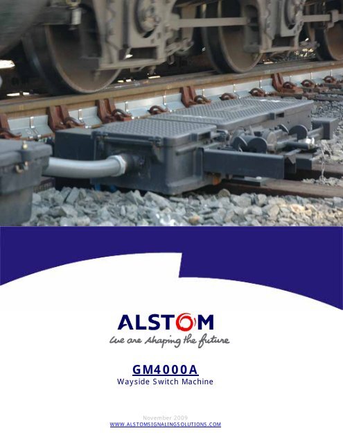
<strong>GM4000A</strong><br />
Wayside <strong>Switch</strong> <strong>Machine</strong><br />
November 2009<br />
WWW.ALSTOMSIGNALINGSOLUTIONS.COM
TABLE OF CONTENTS<br />
<strong>Introduction</strong> ........................................................................................................................... 3<br />
<strong>Product</strong> Chronicle .................................................................................................................... 4<br />
Specifications.......................................................................................................................... 5<br />
Benefits ................................................................................................................................. 6<br />
Features................................................................................................................................. 7<br />
<strong>GM4000A</strong> Configuration Key ....................................................................................................18<br />
<strong>Machine</strong> Mechanical Drawing....................................................................................................19<br />
<strong>GM4000A</strong> <strong>Switch</strong> <strong>Machine</strong><br />
November 2009<br />
2
INTRODUCTION<br />
<strong>GM4000A</strong><br />
WAYSIDE SWITCH MACHINE<br />
Founded on over 100 years of design experience, the <strong>GM4000A</strong> is the industry benchmark when compared to any wayside machine.<br />
The <strong>GM4000A</strong> is designed, engineered and manufactured utilizing ALSTOM’s experience and expertise in the <strong>Switch</strong> <strong>Machine</strong><br />
business to ensure that our customers receive the best value for their purchases.<br />
The revolutionary design paired with its universal capabilities makes the <strong>GM4000A</strong> especially well suited to meet rigorous operating<br />
demands. The advantages are hard to deny; reduced maintenance, faster field-testing, and more control options make this machine<br />
a must-have for Heavy-Volume Rail lines.<br />
With more competitive pricing options than ever before, this machine is the most affordable choice to designate as your Property<br />
Design Standard. ALSTOM is ready to show you how the <strong>GM4000A</strong> can simplify your operations while improving your bottom line.<br />
Our experienced staff of Design & Application Engineers can provide training classes to familiarize your work force with the<br />
<strong>GM4000A</strong>.<br />
This <strong>Product</strong> <strong>Brochure</strong> will introduce you to the key Features and Benefits of the new <strong>GM4000A</strong>. For any additional questions or<br />
information, please contact ALSTOM Signaling’s Customer Service line at 1-800-717-4477.<br />
<strong>GM4000A</strong> <strong>Switch</strong> <strong>Machine</strong><br />
November 2009<br />
3
PRODUCT DESCRIPTION<br />
The <strong>GM4000A</strong> <strong>Switch</strong> <strong>Machine</strong> incorporates all of the features required to meet today's interlocking demands. The machine is<br />
easy to install, operate and maintain. One model does it all! It's truly universal. There is no need to purchase different machines for<br />
different locations, because this unit is a drop-in replacement for any industry machine. Large inventories of spare parts are reduced<br />
because of the <strong>GM4000A</strong> Modularity Design Concept. The machine uses 50% fewer parts than traditional switch machines, and it is<br />
adaptable to all site-specific requirements without having to make application or electrical wiring changes.<br />
With a low 8-3/4” profile, the <strong>GM4000A</strong> is especially well suited for applications with height restrictions. Having the capability to<br />
deliver more than 4,000 lbs. of thrust, this machine is an ideal solution for long turnouts, switch points plagued by extreme<br />
environmental conditions, or locations that have neglected track maintenance. A maintenance-free, brushless servomotor eliminates<br />
worn brush replacements and the need for dynamic snubbing. The machine’s solid-state controller eliminates a mechanical clutch,<br />
provides universal power (85 to 160VAC or 13 to 160VDC), offers field-configurable control (2, 3, 4 or 5 wire), and has an<br />
integrated five-second overload protection which eliminates the need for overload relays. The local control feature also facilitates<br />
maintenance and enables the machine to be operated electrically at the trackside, while performing monthly testing.<br />
The point-detection system indicates normal or reverse switch positions and breaks indication if a switch-point has moved away from<br />
the stock rail. This system also includes mechanical Latch-Out functionality that can be customer configured (restoring, non-restoring<br />
or disabled). Field-obstruction testing and adjustments are simplified with the use of a spoon gauge.<br />
The <strong>GM4000A</strong> is easily configured for single or dual control and right or left hand operation. Its universal footprint matches all<br />
industry standard hole patterns and requires no extra drilling at the time of installation. This machine’s versatility, dramatically<br />
reduced life cycle costs, and operational reliability make it the clear choice to designate it as your Property Design Standard.<br />
<strong>GM4000A</strong> <strong>Switch</strong> <strong>Machine</strong><br />
November 2009<br />
4
SPECIFICATIONS<br />
Applications<br />
Single <strong>Switch</strong><br />
Single & Double Slip <strong>Switch</strong><br />
Derails<br />
Frogs<br />
Field Layouts<br />
Left or Right Hand Throw<br />
Control<br />
Single or Dual control<br />
Mounting Requirements<br />
Universal Footprint that matches all industrystandard<br />
Bolt Patterns<br />
Thrust<br />
Rated Thrust; 4,000 lbs.<br />
(Requires 85V min., 4-second speed setting, and<br />
High-Current setting)<br />
Weight<br />
1,000 lbs.<br />
Motor Type<br />
Maintenance-free Brushless-Servo<br />
No Dynamic Snubbing or Magnetic Detent Needed<br />
Hand Crank<br />
Available for maintenance and emergency use<br />
Uses gearbox torque benefits for easier cranking<br />
Electrical Control Scheme<br />
2, 3, 4 or 5-wire<br />
NO FIELD RE-WIRING REQUIRED!<br />
Control Voltage<br />
8-36 VDC<br />
Throw Bar Stroke<br />
6.5 Inches<br />
<strong>GM4000A</strong> <strong>Switch</strong> <strong>Machine</strong><br />
November 2009<br />
5
BENEFITS<br />
Split-Link Cam Bar<br />
Prevents Opening/Shaving of Lock Rod Slot<br />
Trackside Electrical Operation<br />
Faster Monthly/Quarterly Testing<br />
Fewer Back Injuries<br />
Electronic Overload Protection (Internal)<br />
No Overload Relays Needed<br />
No Mechanical Clutch Maintenance<br />
Brushless Motor<br />
Eliminates Motor Maintenance (brushes / dust)<br />
Solid-State Electronic Controller<br />
Allows Flexibility to design & integrate the <strong>GM4000A</strong><br />
to any existing wiring, without field wiring changes<br />
Limit <strong>Switch</strong>es (Positive-Break Type)<br />
No Contact Finger Adjustments<br />
No Burned Contacts (Milli-Amp Current Draw)<br />
No Frost on Contacts (IP-67 enclosed design)<br />
New Point Detector Design<br />
Easier Installation, Testing, & Maintenance<br />
<strong>GM4000A</strong> <strong>Switch</strong> <strong>Machine</strong><br />
November 2009<br />
6
FEATURES<br />
Hand-Crank & Cut-Out <strong>Switch</strong><br />
Power is cut to the motor when the Hand Crank is inserted<br />
into the allotted slot, keeping the machine from being<br />
operated electrically. It can also break the indication circuit<br />
if desired. The hand crank is strategically located in line<br />
with the gearbox, so the maintainer can turn the crank<br />
effortlessly when performing monthly tests or maintenance.<br />
(Fewer Back-Related Injuries)<br />
Trackside Electrical Operation<br />
The controller is designed to allow maintainers the ability to<br />
operate the machine electrically while performing<br />
maintenance or testing. By simply turning the selector dial<br />
from REMOTE to LOCAL, and then having a “CALL” issued to<br />
the machine from the dispatcher, the machine can be cycled<br />
under power at the machine rather than having to use the<br />
Hand-Crank!<br />
Brushless Motor<br />
The Servo-Type motor is the latest technology when<br />
compared to the massive motors of the past. Compact and<br />
versatile, it will run at both 24 and 110 Volt power inputs.<br />
There is no need to stock 2 different motors for different<br />
voltage areas. From a maintenance perspective, it is much<br />
more maintainer friendly because it lacks motor brushes<br />
that typically wear and need replacing. It is directly wired<br />
to the controller by means of a quick disconnect coupler,<br />
making it easy to connect & disconnect wires when needed.<br />
Lastly, it does not have a Magnetic-Detent or Dynamic<br />
Snubbing Wire.<br />
<strong>GM4000A</strong> <strong>Switch</strong> <strong>Machine</strong><br />
November 2009<br />
7
FEATURES<br />
NO Clutch<br />
The machine does not have a mechanical clutch, which<br />
means Less Maintenance for the Maintainer! The controller<br />
is designed to electrically cut power to the motor if an<br />
obstruction is encountered between the points. Once the<br />
current spike reaches a set, an internal timer is commenced<br />
to remove power from the motor after a 5-Second time<br />
lapse.<br />
NO Overload Relays Needed<br />
Related to the No-Clutch feature are the Internal Overload<br />
Protection Electronics included in the controller. No<br />
Overload Relays are required in the Relay Room. This is a<br />
significant cost reduction when designing new locations that<br />
include a <strong>GM4000A</strong>, or an existing location refurbishment.<br />
Reference LED’s for Troubleshooting<br />
The top surface of the Controller is clustered with LED’s to<br />
help diagnose any potential fault. This is extremely helpful<br />
when returning the machine into service is time sensitive!<br />
RUN:<br />
LOCAL:<br />
REMOTE:<br />
OVER LOAD:<br />
CTRL FAULT:<br />
MOTOR FAULT:<br />
Motor is running<br />
Control is transferred to maintainer at<br />
machine<br />
Dispatch has control of machine<br />
<strong>Machine</strong> was recently obstructed<br />
Controller is damaged or Input Power from<br />
equipment room is varying or incorrect<br />
(i.e.: Under Voltage)<br />
Motor is damaged<br />
<strong>GM4000A</strong> <strong>Switch</strong> <strong>Machine</strong><br />
November 2009<br />
8
FEATURES<br />
Maintenance Free Gearbox<br />
The mating gearbox to the motor is a completely sealed,<br />
self-lubricated Oil-Bath gear collection that does not require<br />
maintenance for long periods of time. 10-15 years of<br />
normal use should be the general operating life of the oil<br />
before it requires inspection. Even then, it may be in fine<br />
condition. The unit is easily removed using standard tools.<br />
Roughly a 5-minute process, with no Gear Timing required.<br />
Main Dive Module<br />
The Mechanical heart of the machine; it is the driving force<br />
behind the 4000 lbs. of thrust through the throw bar. It is<br />
also the interchange for the Hand Throw Module, Power<br />
Operation, and the Motor Limit <strong>Switch</strong>es. The unit is easily<br />
removed using standard tools. Roughly a 10-minute<br />
process!<br />
Gear Timing<br />
The Gears on the Main drive Module are all timed from the<br />
mid-stroke position. A clever little window allows you to<br />
easily identify and set the 4 Time-Marks located on the toplevel<br />
gears.<br />
<strong>GM4000A</strong> <strong>Switch</strong> <strong>Machine</strong><br />
November 2009<br />
9
FEATURES<br />
Throw Bar<br />
The Throw Bar is a standard design. It can withstand<br />
20,000 lbs. of thrust during a trailing movement, allowing<br />
you to salvage most of the machine and limit repairs to the<br />
layout connecting rods.<br />
Hand Throw<br />
The hand throw is easily repositioned from a left-hand to a<br />
right-hand orientation, with an easy 15-Minute procedure.<br />
Split-Link Cam Bar<br />
The Split-Link Cam Bar is a patented design, which prevents<br />
the machine from Opening / Shaving the Lock Rod slot when<br />
fouled (Out of Adjustment).<br />
<strong>GM4000A</strong> <strong>Switch</strong> <strong>Machine</strong><br />
November 2009<br />
10
FEATURES<br />
Selector Lever<br />
The machine comes with a Hand-Mode / Power-Mode<br />
Selector lever, which cuts power & correspondence when<br />
rotated to the Hand-Mode position.<br />
Hand Throw Cut-Out <strong>Switch</strong><br />
The Selector Lever actuates the Plunger on the Hand Throw<br />
Cut Out <strong>Switch</strong>. It is located on the Bottom Level of the<br />
Main Drive Module.<br />
Latch-Out<br />
Latch-Out is a “Mechanical Memory Mechanism” that helps<br />
preserve a momentary Loss-of-Indication. Without a latch<br />
out feature, a loose point could Theoretically:<br />
1. Move ¼” away from the Stock Rail & cause a loss of<br />
Indication<br />
2. Move Back against the Stock Rail & regain Indication<br />
3. All within a split second<br />
If the dispatcher is not watching the monitor, there is no<br />
way to know that a potential issue has occurred at the<br />
switch.<br />
The Factory Adjusted Latch-Out Mechanism will<br />
mechanically retain the contacts “OPEN” in the event that<br />
the Point Detector Rod moved ¼” away from the stock rail.<br />
This loss of indication will alert the dispatcher to an<br />
apparent issue in the field, and allow a maintainer to<br />
evaluate the problem.<br />
A Maintainer can select two Electrical Options.<br />
Restorable Mode:<br />
Allows the dispatcher to throw the machine in the opposite<br />
direction after a Latch-Out fault (bypassing the Latch-Out<br />
Mechanism)<br />
Non-Restorable Mode:<br />
Prevents Remote operation of the machine by a dispatcher<br />
after a Latch-Out fault. Can only be reset by a maintainer<br />
at the switch.<br />
<strong>GM4000A</strong> <strong>Switch</strong> <strong>Machine</strong><br />
November 2009<br />
11
FEATURES<br />
Terminal & Gearbox Heaters<br />
Depending on climate conditions and customer preference,<br />
heaters are available to help reduce condensation / frost.<br />
The 24 or 110-Volt heaters are available for the Terminal &<br />
Gearbox areas. These are paper-thin Thermofoil Heaters<br />
that provide heat to the areas that are needed.<br />
NO Floating of the Lock Rod<br />
Using a Spoon Gauge, a maintainer can now perform the<br />
monthly point detector test independently from the Lock<br />
Rod, to verify the absence of correspondence with a ¼” or<br />
3/8” obstruction.<br />
Air Vents<br />
The <strong>Machine</strong> Housing has 2 air vents to help the machine<br />
“breath” during fluctuating weather patterns that typically<br />
cause condensation.<br />
<strong>GM4000A</strong> <strong>Switch</strong> <strong>Machine</strong><br />
November 2009<br />
12
FEATURES<br />
Cycle Counter<br />
A cycle counter accessory is available with the machine to<br />
keep track of line-use and to make maintenance records<br />
easier. It can be installed in line with the correspondence<br />
Relay in the Instrument House.<br />
<strong>Machine</strong>-Mounted Latch Stands<br />
The machine housing is designed with Integrated Latch<br />
stands. No longer is it required to drill holes into the Ties<br />
for mounting of separate latch stands.<br />
Universal Bolt Hole Pattern<br />
Fits any Bolt-Hole Mounting Pattern, allowing you to<br />
substitute any machine with the <strong>GM4000A</strong>. Additional hole<br />
drilling into the ties is no longer needed.<br />
<strong>GM4000A</strong> <strong>Switch</strong> <strong>Machine</strong><br />
November 2009<br />
13
FEATURES<br />
Low-Profile<br />
The 8 ¾” Profile reduces damage caused by frequent<br />
dragging of equipment.<br />
Lightweight Covers<br />
Dramatically reduce back injuries! Strong, lightweight castaluminium<br />
covers have replaced the old Heavy, cast-steel<br />
covers.<br />
Modularity Design Concept<br />
Large inventories of spare parts are reduced thanks to the<br />
<strong>GM4000A</strong> Modularity Design Concept. The machine is<br />
modularly designed, so any part that fails in the field can be<br />
replaced in 15 minutes or less. This allows you to keep your<br />
trains moving while failed units are repaired in the shop, at<br />
the maintainer’s leisure.<br />
<strong>GM4000A</strong> <strong>Switch</strong> <strong>Machine</strong><br />
November 2009<br />
14
FEATURES<br />
Wide or Narrow Notch Lock Rods<br />
Both Narrow & Wide Notch Locks Rods are available for your<br />
custom machine.<br />
Speed, Current, & Selection<br />
<strong>Switch</strong> machine speed at 24 VDC speed is approximately 24<br />
seconds. However, at 110 VDC or VAC there are 2 available<br />
speeds: 4 seconds and 15 seconds. Default at 110 VDC or<br />
VAC is 15 seconds. The suggested current configuration of<br />
the <strong>GM4000A</strong> is the high-current operation option. At this<br />
setting the switch machine produces up to 4000 pounds of<br />
force at the end of stroke.<br />
2, 3, 4, & 5 Wire Mode Compatible<br />
The controller can be set for 2-wire (Model 55E), 3-wire<br />
(model 5E/5F and M23), 4-wire (model 5G/5H), or 5-wire<br />
(model M23) power & control through the different wiring<br />
configurations. There are four motor control wiring<br />
configurations that determine how incoming wiring is<br />
connected to the terminals AND must be configured through<br />
the controller wiring connection. The power lines are 24<br />
VDC, 110 VDC, or 110 VAC. The four field wiring<br />
configurations shown on the right show the TB1 terminal<br />
locations.<br />
2-wire 3– Wire 4-wire 5-wire<br />
Power TB1–1 TB1–1 TB1–1 TB1–1<br />
Power TB1–2 TB1–2 TB1–2<br />
Power TB1–3 TB1–3 TB1–3<br />
Control<br />
TB1–4<br />
Control<br />
TB1–5<br />
Auxiliary<br />
TB1–8 (2 wires)<br />
Configuration<br />
Wiring Connection<br />
2-wire Mode Motor Control Connect P1-15 (BLACK) to HC-11<br />
(BLUE) Hand Crank <strong>Switch</strong> Lead<br />
3-wire Mode Motor Control Connect P1-15 (BLACK) to HC-11<br />
(BLUE) Hand Crank <strong>Switch</strong> Lead<br />
AND<br />
Connect P1-22 (YELLOW) to P1-23<br />
(YELLOW)<br />
4-wire Mode Motor Control Connect P1-7 (WHITE) to HC-11<br />
(BLUE) Hand Crank <strong>Switch</strong> Lead<br />
AND<br />
Connect P1-22 (YELLOW) to P1-23<br />
(YELLOW)<br />
5-wire Mode Motor Control For the three control wires connect<br />
P1-15 (BLACK) to HC-11 (BLUE)<br />
Hand Crank <strong>Switch</strong> Lead<br />
AND<br />
Connect P1-22 (YELLOW) to P1-23<br />
(YELLOW)<br />
THEN<br />
Verify that the two auxiliary wires are<br />
connected to post TB1-8 (see Figure<br />
3–2 for the location of TB-1)<br />
High Speed Operation Connect P1-17 (GREEN) to P1-10<br />
(GREEN)<br />
Low Speed Operation Disconnect P1-17 (GREEN) to P1-10<br />
(GREEN)<br />
High Current Operation Connect P1-17 (RED) to P1-3 (RED)<br />
Low Current Operation Disconnect P1-17 (RED) to P1-3<br />
(RED)<br />
Low Voltage Shutoff Disconnect P1-17 (GRAY) to P1-11<br />
(GRAY)<br />
<strong>GM4000A</strong> <strong>Switch</strong> <strong>Machine</strong><br />
November 2009<br />
15
FEATURES<br />
Voltage Frequency<br />
The machine will operate at 50Hz, 60Hz, or 100Hz AC.<br />
1 1<br />
1<br />
POWER<br />
This allows designers more flexibility for new-work<br />
construction.<br />
SHUNT<br />
POWER<br />
POWER<br />
12V CONTROL<br />
12V CONTROL<br />
INDICATION<br />
HAND THROW<br />
HAND THROW<br />
AUX<br />
LO<br />
*<br />
LO<br />
* *<br />
12<br />
TB3<br />
12<br />
TB2<br />
TB1<br />
12<br />
* MOTOR LIMIT<br />
** HAND CRANK<br />
Control Voltage<br />
The machine will accept Control Voltage in the range of:<br />
Typical Polarized <strong>Switch</strong> Repeater Circuit, Single <strong>Switch</strong><br />
Point detector contacts are shown in position for<br />
right hand point normally closed.<br />
INDICATION IN HAND THROW<br />
9-35 VDC.<br />
TB-3<br />
TB-2<br />
TB-1<br />
1<br />
shunt<br />
2<br />
1<br />
shunt<br />
2<br />
1<br />
power<br />
2<br />
power<br />
RH point<br />
normally<br />
closed<br />
LH point<br />
normally<br />
closed<br />
3<br />
shunt<br />
4<br />
3<br />
shunt<br />
4<br />
3<br />
4<br />
control<br />
NWP<br />
WP<br />
NW<br />
5<br />
indicate<br />
6<br />
5<br />
indicate<br />
6<br />
5<br />
6<br />
hand thr<br />
7<br />
indicate<br />
8<br />
7<br />
indicate<br />
8<br />
7<br />
8 aux<br />
Note 1<br />
DC+<br />
DC+<br />
WP<br />
9<br />
motor limit<br />
10<br />
9<br />
motor limit<br />
10<br />
9<br />
latch out<br />
10<br />
WP<br />
NWP<br />
11<br />
11<br />
11<br />
aux<br />
hand crk<br />
aux<br />
DC-<br />
DC-<br />
12<br />
12<br />
12<br />
right<br />
left<br />
No<br />
pro<br />
ind<br />
cla<br />
<strong>GM4000A</strong> <strong>Switch</strong> <strong>Machine</strong><br />
November 2009<br />
16
FEATURES<br />
Dual Wire Entrance ports<br />
A second wire entrance port is available in the event that an<br />
inconvenient junction box location requires a longer wire<br />
run.<br />
One-Piece Housing<br />
The outdated “Layered Approach” of design, has been<br />
replaced with ALSTOM’s Modularity Design Concept. The<br />
One-Piece Case is a welcomed enhancement that allows for<br />
easier access to all parts. Maintenance & Repairs are much<br />
easier.<br />
<strong>GM4000A</strong> <strong>Switch</strong> <strong>Machine</strong><br />
November 2009<br />
17
<strong>GM4000A</strong> Configuration Key for Model Number Determination<br />
Cod MODEL NUMBER<br />
WM<br />
e<br />
CONTROL CONFIGURATION<br />
A GMV00-000-01 Dual Control (Hand Throw, With Hand Crank Capability)<br />
B GMV00-000-02 Dual Control (Hand Throw, W/O Hand Crank Capability)<br />
C GMV00-000-03 Single Control (No Hand Throw, With Hand Crank Capability)<br />
D<br />
GMV00-000-04 Single Control (No Hand Throw, With Hand Crank Capability, No Latch<br />
Out)<br />
MACHINE ORIENTATION<br />
L Left Hand<br />
R Right Hand<br />
LOCK RODS<br />
N GM050-300-01 Narrow Notch Threaded End 3.5 – 6.5 Inch Adjustment<br />
W GM050-300-02 Wide Notch Threaded End 3.5 – 6.5 Inch Adjustment<br />
S GM050-300-03 Narrow Notch Spade End 3.5 – 6.5 Inch Adjustment<br />
B GM050-300-04 Wide Notch Spade End 3.5 – 6.5 Inch Adjustment<br />
C GM050-300-05 Wide Notch Spade End 4.5 – 6.0 Inch Adjustment<br />
E GM050-300-07 Narrow Notch Threaded End 3.0 – 6.5 Inch Adjustment<br />
For Lock Rods –01 Thru –07 Add: (4) GMV00-012-00, (2) GMV00-013-00 AND (2) GMV00-014-00<br />
X No Lock Rod Add: Only (2) Covers GMV00-011-00<br />
POINT DETECTOR ROD<br />
T GMV00-500-01 Swivel Threaded End With Rivets<br />
S GMV00-500-02 Solid Spade End<br />
P GMV00-500-03 Swivel Threaded End With Grease Pin<br />
C GMV00-500-04 Swivel Threaded End With Grease Pin 4.5-6 inch<br />
CONTROLLER CONFIGURATION<br />
S GMV00-043-00 Standard Controller<br />
E GMV00-044-00 Enhanced Controller<br />
GEAR BOX HEATER<br />
B 55290-040-00 (24VDC & 110VAC/DC) Gear Box Heater<br />
N NO Gear Box Heaters<br />
CONDENSATION HEATERS<br />
A 55290-041-00 24 Volt Heater<br />
B 55290-042-00 110 Volt Heater<br />
C Both Heaters<br />
N NO Condensation Heater<br />
LATCH STANDS<br />
L GMV00-400-01 (2) Required Per <strong>Machine</strong><br />
N No Latch Stands<br />
TOOLS (Optional Accessory)<br />
B Hand Crank & Spoon Gauge (.38/.25) & Tool Kit (GMA50-012-00, GMA50-002-00, GMK50-000-01)<br />
S GMA50-002-00 Spoon Gauge (.38/.25)<br />
H GMA50-012-00 Hand Crank<br />
E GMA50-013-00 Hand Crank, Hex End And: 50570-018-00 Ratcheting Crank<br />
C GMA50-014-00 Spoon Gauge (6.0/4.5mm)<br />
K GMK50-000-01 Maintainer Tool Kit<br />
N NO Tools<br />
HAND THROW LETTER KIT (Optional Accessory)<br />
K GMK50-004-01 Letters “N” & “R”<br />
N NO Hand Throw Letter Kit<br />
HARNESS ADAPTER OPTION<br />
A GMK50-013-01 Kit, Polarized <strong>Switch</strong> Repeater Harness<br />
H GMK50-010-01 Wire Harness Adapter for Motor End Wire Entrance<br />
N NO Harness Adapter<br />
LATCH OUT<br />
A No Latch Out<br />
b<br />
C<br />
Restorable Latch Out<br />
Restorable Latch Out<br />
D Non-Restorable Latch Out (GMA50-107-01)<br />
ADDITIONAL ACCESSORY TO BE ORDERED SEPARATELY<br />
GMA50-100-01 Puller Complete, Bushing<br />
<strong>GM4000A</strong> <strong>Switch</strong> <strong>Machine</strong><br />
November 2009<br />
18
<strong>GM4000A</strong> <strong>Machine</strong> Mechanical Drawing<br />
HAND CRANK<br />
(GMA50-012-00)<br />
HAND CRANK DOOR<br />
(OPEN) (GMV00-070-01)<br />
CONTROLLER,<br />
STANDARD (GMV00-043-00)<br />
ENHANCED, SHOWN (GMV00-044-00)<br />
WIRE HARNESS<br />
(GMV00-900-01)<br />
MOTOR AND<br />
172:1 GEAR BOX<br />
(GMV00-025-01)<br />
LATCH STAND<br />
(GMV00-400-01)<br />
THROW BAR<br />
(GMV00-002-00)<br />
MAIN DRIVE<br />
(GMV00-100-01)<br />
POINT DETECTOR<br />
SWITCH MODULE<br />
(GM050-800-02)<br />
HAND THROW LEVER,<br />
COMPLETE<br />
(GMV00-200-01)<br />
LATCH STAND<br />
(GMV00-400-01)<br />
LOCK ROD<br />
(GM050-300-0#)<br />
CONDENSATION HEATER<br />
(55290-041-00, 24VDC or VAC<br />
OR<br />
55290-042-00, 110 VDC or VAC)<br />
POINT DETECTOR ROD<br />
(GMV00-500-0#)<br />
POINT DETECTOR COMPLETE<br />
(GMV00-700-01)<br />
<strong>GM4000A</strong> <strong>Switch</strong> <strong>Machine</strong><br />
November 2009<br />
19
For Questions and Inquiries, Contact Customer Service at<br />
1-800-717-4477<br />
OR<br />
www.alstomsignalingsolutions.com<br />
ALSTOM Signaling Inc.<br />
1025 John Street<br />
West Henrietta, New York 14586<br />
U.S.A.


