RAILING INSTALLATION GUIDELINES - Azek
RAILING INSTALLATION GUIDELINES - Azek
RAILING INSTALLATION GUIDELINES - Azek

You also want an ePaper? Increase the reach of your titles
YUMPU automatically turns print PDFs into web optimized ePapers that Google loves.
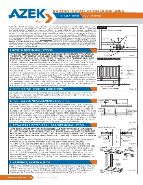
<strong>RAILING</strong> <strong>INSTALLATION</strong> <strong>GUIDELINES</strong><br />
For AZEK Premier<br />
AZEK Trademark<br />
AZEK Rail should be installed using the same good building principals used to install wood or composite<br />
rail and in accordance with the local building codes and the installation guidelines included below.<br />
AZEK Building Products Inc. claims no liability or responsibility for the improper installation of<br />
this product. AZEK Rail may not be suitable for every application and it is the sole responsibility of the<br />
installer to be sure that AZEK Rail is fit for the intended use. Since all installations are unique, it is also the<br />
installer’s responsibility to determine the specific requirements for each Rail application. AZEK Building Products<br />
recommends that all designs be reviewed by a licensed architect, engineer or local building official before installation.<br />
If you have any questions or need further assistance, please call AZEK Customer Service at 1-877-ASK-AZEK,<br />
(877) 275-2935 or visit our website at www.azek.com. Please read all instructions completely before starting<br />
any part of the installation. Each railing kit comes complete with all parts, hardware and installation guide to<br />
install one complete rail section (excluding posts.) Railing sections have been pre-cut to 6 ft. or 8 ft. lengths. Check to<br />
ensure that the kit is complete. Safety: Always wear goggles when handling, cutting, drilling and fastening materials.<br />
Note: Check local code requirements.<br />
1. POST SLEEVE <strong>INSTALLATION</strong>S<br />
NOTE: POST SLEEVES ARE NOT DESIGNED TO BE USED IN STRUCTURAL APPLICATIONS.<br />
THEREFORE, THEY SHOULD NOT BE USED WHERE THEY MAY BE SUBJECT TO WEIGHT<br />
BEARING APPLICATIONS SUCH AS SUPPORTS FOR A ROOF OF A PORCH OR DECK. POST<br />
SLEEVES SHOULD NOT BE NOTCHED FOR <strong>INSTALLATION</strong>. The Post Sleeve has been designed<br />
to slide easily over a nominal wood 4” x 4” (min. 3 3/8” x 3 3/8”, max. 3 9/16” x 3 9/16”)<br />
post after the deck sub-structure is complete and the deck boards have been fastened. The<br />
4” x 4” should extend down to the bottom of the rim joist and be completely “BOXED IN”<br />
around all 4 corners for the firmest attachment (see Figure 1). At this time, make sure the 4” x<br />
4” wood posts are level and plumb to ease the installation of your railing system. If the nominal<br />
wood 4” x 4” post is twisted or oversized it will be necessary to shave the 4” x 4” wood post.<br />
Next, slide the Post Sleeve over the wood post (Do not force the Post Sleeve over the 4” x 4”<br />
as it may eventually lead to a crack or split). Post Sleeves may also be used over a wood post<br />
installed with a Surface Mount Bracket or over a Tallboy Surface Mount Bracket. For installation<br />
of a wood post to concrete, refer to the Surface Mount Bracket installation instructions or your<br />
local dealer. When using 6” x 6” post sleeves, a minimum 5 3/8” x 5 3/8” and a maximum 5<br />
9/16” x 5 9/16” outside post dimension is required for a proper fit.<br />
2. POST SLEEVE HEIGHT CALCULATIONS<br />
Calculate and cut Post Sleeve to required height (see Figure 2). Slide Post Sleeve over 4” x 4”<br />
wood post into position. For 36” rail, cut Post Sleeve to a minimum of 38”. For 42” rail, cut<br />
Post Sleeve to a minimum of 44”.<br />
3. POST SLEEVE MEASUREMENTS & CUTTING<br />
Measure between posts, top and bottom to obtain the rail length. Also check the opening<br />
to ensure the Post Sleeves, newel posts or walls where the rail is to be installed are square<br />
and plumb. To obtain proper baluster spacing, measure half the determined rail length on<br />
the retainer/bottom rail from the center of the part. Note: This could be on a hole or from the<br />
center between holes only. If there is not enough room to fit the bracket and baluster side by<br />
side, alter the rail center from center hole to between holes or from between holes to center<br />
hole (this will move your baluster 2 5/8” either direction). Be sure not to allow any more than<br />
4” between post sleeve and first baluster. If a rail must be cut so that the baluster sits on the<br />
bracket, the baluster end must be notched to fit around bracket and bracket bolt.<br />
4. RETAINERS & BOTTOM RAIL BRACKET <strong>INSTALLATION</strong><br />
NOTE: THE DISTANCE BETWEEN THE BALUSTER AND THE POST SHOULD NOT EXCEED<br />
4”. MOST BUILDING CODES REQUIRE THAT A 4” SPHERE SHALL NOT PASS THROUGH THE<br />
RAIL AT ANY POINT. PLEASE NOTE THAT IT IS THE SOLE RESPONSIBILITY OF THE INSTALL-<br />
ER TO BE SURE THE AZEK RAIL MEETS THE LOCAL CODES AND IS APPLICABLE FOR EACH<br />
<strong>INSTALLATION</strong>.<br />
To comply with the above statement, both top and bottom rails of 6ft sections, must be cut a<br />
minimum of 7/8” to allow no more than 4” spacing between the baluster and post.<br />
Place the “U” shaped end of the painted stainless steel bracket on the underside of the<br />
retainer and bottom rail. Be sure to place the bracket just slightly inside (1/16”) the cut edge<br />
of the retainer and bottom rail. Mark and drill pilot holes with a 3/16” bit. Drill out the two<br />
mounting holes to 3/8”. Note: When drilling for the bottom rail, drill through bottom wall<br />
only – do not drill through the top surface. Using the supplied 6mm Allen Wrench, screw<br />
the threaded inserts into the 3/8” holes from the bottom until flush. Be careful not to over<br />
torque. Next, fasten each bracket with (2) 1/4” x 20” panhead bolts to the underside of the<br />
retainer and bottom rail.<br />
5. ASSEMBLE, FASTEN & SLIDE<br />
Align the ends of each Baluster with the pre-drilled holes in the Retainer (see Figure 5). Using the<br />
1 3/4” # 8 wood screws, fasten the Balusters to the Retainer first, through the pre-drilled holes. Do<br />
not over torque. Align the ends of the Balusters with the holes in the Bottom Rail and fasten the<br />
Balusters to the Bottom Rail through the pre-drilled holes using the 3” # 8 wood screws.<br />
TOP VIEW<br />
TOP VIEW<br />
TOP VIEW<br />
POST HEIGHT CALCULATION<br />
CARRIAGE<br />
POST BOLTS 2" x HEIGHT 8" DECK JOIST CALCULATION<br />
CENTER SUPPORT<br />
POST 4x4 HEIGHT WOOD CALCULATION<br />
POST<br />
2" x 8" DECK JOIST<br />
4x4 WOOD POST<br />
POST SLEEVE<br />
POST SLEEVE<br />
1" DECK 1" DECK<br />
SURFACE<br />
RETAINER AND BOTTOM RAIL<br />
CARRIAGE<br />
CARRIAGE<br />
BOLTS<br />
BOLTS<br />
POST SUPPORT<br />
MATERIAL<br />
1/2" x 8" or 10"<br />
CARRIAGE BOLT<br />
SUPPLIED ALLEN<br />
WRENCH THREADED INSERT<br />
POST CAP<br />
ACCESSORY<br />
POST CAP<br />
ACCESSORY<br />
3/8"<br />
CENTER SUPPORT<br />
CENTER SUPPORT<br />
THREADED INSERT<br />
DECK JOISTS<br />
2" x 8" DECK JOIST<br />
2" x 8" DECK 4x4 JOIST WOOD POST<br />
4x4 WOOD POST<br />
RETAINER AND BOTTOM RAIL<br />
3/8"<br />
RETAINER AND BOTTOM RAIL<br />
3/8"<br />
1 3/4" #8<br />
WOOD<br />
SCREWS<br />
SUPPLIED ALLEN<br />
(SUPPLIED) WRENCH<br />
1 3/4" #8<br />
WOOD<br />
SCREWS<br />
(SUPPLIED)<br />
1 3/4" #8<br />
WOOD<br />
SCREWS 3" #8<br />
(SUPPLIED) WOOD<br />
SCREWS<br />
(SUPPLIED)<br />
3" #8<br />
WOOD<br />
SCREWS<br />
(SUPPLIED)<br />
POST SUPPORT<br />
MATERIAL<br />
DECK JOISTS<br />
1 7 /8"<br />
POST CAP<br />
ACCESSORY<br />
1 7 /8"<br />
1/2" x 8" or 10"<br />
CARRIAGE BOLT<br />
POST SLEEVE<br />
POST SLEEVE<br />
1 7 /8"<br />
1 7 /8"<br />
POST HEIGHT CALCULATION<br />
POST SLEEVE<br />
1" DECK<br />
SURFACE<br />
SUPPLIED ALLEN<br />
WRENCH<br />
POST SUPPORT<br />
MATERIAL<br />
THREADED INSERT<br />
DECK JOISTS<br />
1 7 /8"<br />
1/2" x 8" or 10"<br />
CARRIAGE BOLT<br />
POST SLEEVE<br />
36"<br />
Or<br />
42"<br />
PRE-DRILLED RETAINER<br />
PRE-DRILLED<br />
BOTTOM RAIL<br />
(5 7/32" O.C.)<br />
PRE-DRILLED RETAINER<br />
5 7/32"<br />
BALUSTERS<br />
4" OPENING<br />
1 7 /8"<br />
PRE-DRILLED RETAINER<br />
BALUSTERS<br />
4" OPENING<br />
PRE-DRILLED<br />
BOTTOM RAIL<br />
(5 7/32" O.C.)<br />
BALUSTERS<br />
4" OPENING<br />
5 7/32"<br />
PRE-DRILLED<br />
BOTTOM RAIL<br />
(5 7/32" O.C.)<br />
Figure 1<br />
4" x 4" WOOD POST<br />
(1) 38 (For 36")<br />
Or<br />
4" x 4" WOOD POST<br />
(2) 44" (For 42")<br />
GRADE LEVEL<br />
GRADE LEVEL<br />
Figure 2<br />
36" (1) 38 (For 36")<br />
36" (1) 38 (For 36")<br />
Or Or Or Or<br />
42" (2) 42" 44" (2) (For 44" 42") (For 42")<br />
GRADE LEVEL<br />
GRADE LEVEL<br />
Figure 2<br />
Figure 3<br />
RAIL MOUNTING<br />
1/4" 1/2” PAN HEAD<br />
BRACKET<br />
BOLT<br />
RAIL MOUNTING<br />
BRACKET<br />
HANDRAIL<br />
HANDRAIL<br />
NUT AND WASHER<br />
NUT AND WASHER<br />
36"<br />
Or<br />
42"<br />
Figure 1<br />
Figure 1<br />
RAIL MOUNTING<br />
BRACKET<br />
NUT AND WASHER<br />
4" x 4" WOOD POST<br />
Figure 2<br />
Figure RETAINER OR 3<br />
1/4" PAN HEAD<br />
BOLT<br />
BOTTOM RAIL<br />
RETAINER OR<br />
BOTTOM RAIL<br />
Figure Figure 3 4<br />
HANDRAIL<br />
Figure 1<br />
Figure 3<br />
HANDRAIL<br />
SLIDES OVER<br />
RETAINER<br />
(1) 38 (For 36")<br />
Or<br />
(2) 44" (For 42")<br />
Figure 2<br />
1/4" PAN HEAD<br />
BOLT<br />
RETAINER OR<br />
BOTTOM RAIL<br />
HANDRAIL<br />
SLIDES OVER<br />
RETAINER<br />
HANDRAIL<br />
SLIDES OVER<br />
RETAINER<br />
Figure 4<br />
Figure 5<br />
www.AZEK.com 33 ©2010 AZEK Building Products<br />
3" #8<br />
WOOD<br />
SCREWS<br />
(SUPPLIED)<br />
5 7/32"<br />
Figure 4
6. CENTER <strong>RAILING</strong> SUPPORT<br />
Fasten center support in center of railing using 1” self-tapping screws. (see Figure 6a & b)<br />
Check Chart 1 for the proper cut length for your style of rail. Center support must be cut to meet local railing height<br />
requirements.<br />
CENTER SUPPORT SIZE<br />
CDN Premier 2 15 /16”<br />
CDN Trademark 2 5 /8”<br />
US Premier 4 5 /16”<br />
** indicates size supplied<br />
CENTER SUPPORT SIZE<br />
US Trademark 4 5 /8”**<br />
US Reserve 4 3 /8”<br />
** indicates size supplied<br />
Chart 1<br />
1 3/4" WOOD SCREW<br />
CENTER<br />
SUPPORT<br />
BLOCK<br />
1 7/16"<br />
7/16"<br />
CENTER<br />
SUPPORT<br />
BRACKET<br />
Figure 6a<br />
BOTTOM RAIL<br />
PRE-DRILLED<br />
HOLES<br />
1" SELF-<br />
DRILLING SCREWS<br />
CENTER SUPPORT<br />
BLOCK<br />
BALUSTERS<br />
4"<br />
Figure 6b<br />
CENTER SUPPORT<br />
BRACKET<br />
CENTER OF BOTTOM RAIL<br />
NOTE: LEVEL <strong>RAILING</strong> PRIOR<br />
TO MARKING & DRILLING<br />
MARK & DRILL<br />
HOLES<br />
#14 x 2" SCREWS<br />
Figure 7<br />
POST<br />
7. LEVEL & ATTACH <strong>RAILING</strong><br />
• Place assembled railing between Posts and level. • Mark holes. • Remove assembled railing.<br />
• Drill pilot holes in the Posts with a 1/4” drill bit. (Be sure to only drill through post sleeve.) • Re-position assembled railing.<br />
• Fasten the section to the post using the 14 x 2” stainless steel painted screws supplied with a #3 square drive bit.<br />
• When using Tallboy SMB be sure to use a 7/32” drill bit through post sleeve and SMB wall.<br />
IMPORTANT: DO NOT OVER TORQUE SCREWS WHEN FASTENING RAIL TO POSTS AS THIS MAY CAUSE POST<br />
SLEEVES TO CRACK.<br />
8. POST CAP APPLICATION<br />
Apply generous amount of construction grade adhesive to top edges of Post Cap and press Post Cap firmly into place.<br />
9. FASTEN HANDRAIL TO RETAINER<br />
Take remaining self drilling screws that were used in Step 6 and install up through the retainer into the handrail to lock it in<br />
place. Space screws evenly over the span. For care and cleaning instructions visit our website.<br />
<strong>RAILING</strong> CONVERSION FOR STAIRS<br />
The assembly and installation of stair rail is the same as for horizontal rail (see over) except for changes detailed below.<br />
Please read instructions for horizontal rail before attempting to assemble and convert to stair rail.<br />
1. PREPARATION<br />
First check the rise and run of the stairs to determine the proper stair rail angle. (see Figure 8) Check the rail opening to<br />
ensure the sleeves, newels or walls where the stair rail is to be installed are square and plum. Measure between the Post<br />
Sleeves to obtain the rail length. Be sure to measure between the Post Sleeves at both top and bottom.<br />
TIP: Ensure the proper fit by cutting a test piece of wood to the previously determined length and angle and fit it into<br />
the opening. Once the proper measurements have been confirmed, measure the handrail and retainer from the center of<br />
each part and trim an equal amount from each side to obtain the top length measured<br />
Figure 8<br />
between the sleeves.<br />
4<br />
3<br />
2<br />
2. BALUSTERS Cut Balusters to proper angle, top and bottom. Keep length identical.<br />
Figure 8 9<br />
1. Stair Angle<br />
4<br />
3. DRILLING HOLES RETAINER AND BOTTOM RAIL<br />
The Retainer and Bottom Rail have been factory drilled for “horizontal” rail<br />
installations to assist with the assembly. For a stair rail installation, the Retainer and<br />
Bottom rail holes will need to be re-drilled to match the required stair rail angle.<br />
From the center of the top holes, draw a line the proper angle down the side of the<br />
bottom rail to be used as a guide (see Figure 9). Using a 3/16th bit, drill through the<br />
top hole following the angled guideline, and through the bottom of the rail making<br />
sure to drill through as close to the center line as possible.<br />
TIP: Use a drill guide to ensure accuracy and see our website for additional<br />
information.<br />
4. MOUNTING BRACKETS<br />
Use the Stainless Steel Hinged Bracket included in the kit to fasten railing section to<br />
the posts. IMPORTANT: DO NOT OVER TORQUE SCREWS WHEN FASTENING TO<br />
THE POSTS AS THIS MAY CAUSE THE POST SLEEVE TO CRACK.<br />
5. ASSEMBLE AND INSTALL<br />
Assemble as per horizontal rail installation instructions Step #5.<br />
Note: The 2 1/2” handrail is placed onto the retainer and secured using the self drilling<br />
screws supplied.<br />
Manufactured under AZEK Building Products U.S. Patent 6,702,259 B2<br />
©2010 AZEK Building Products<br />
34 www.AZEK.com