Installation Instructions - BB&S Treated Lumber of New England
Installation Instructions - BB&S Treated Lumber of New England
Installation Instructions - BB&S Treated Lumber of New England

You also want an ePaper? Increase the reach of your titles
YUMPU automatically turns print PDFs into web optimized ePapers that Google loves.
TRX & SRX Vinyl Railing<br />
<strong>Installation</strong> <strong>Instructions</strong><br />
NOTE: These instructions must be followed exactly as written and the material used must be exactly as shown in the instructions. Any deviation from the instructions or variation in the<br />
material used/installed may result in an unsuccessful installation.<br />
Post Applications<br />
Aluminum Post Mount for Concrete & Wood<br />
Applications:<br />
If using a Standard Aluminum Post Mount (Residential) or Heavy-Duty<br />
Aluminum Post Mount (Commercial), see the instructions included with<br />
your mount.<br />
4” x 4” Wood Support Posts:<br />
Note: A 4” x 4” Vinyl Post does not have any structural strength to support weight<br />
bearing ro<strong>of</strong>s.<br />
A 4” x 4” wood treated post (which measures<br />
3½” x 3½”) will slide inside the vinyl post to<br />
support the weight. Most <strong>of</strong> the time, your posts<br />
are installed after the ro<strong>of</strong> is in place. Usually,<br />
there is a beam the post can be attached to.<br />
Following are steps needed to install this post<br />
system. We do realize you can run into many<br />
different situations at the job site. In those cases,<br />
field modifications may be needed.<br />
Step 1:<br />
Cut vinyl post and wood post to size. To<br />
determine wood post length, stack (2) top/bottom<br />
support post mounts and measure distance<br />
between mounts and beam. To determine vinyl<br />
post length, measure distance between floor and<br />
beam and deduct 1”. This will ensure no weight<br />
bearing on the vinyl post. NOTE: On wood,<br />
make sure there is structural strength to support<br />
the weight <strong>of</strong> the ro<strong>of</strong>.<br />
Step 2:<br />
All material will need to be applied to the post before installation. Slide post<br />
flairs over top and bottom <strong>of</strong> post. Slide wood post inside vinyl post. Insert a<br />
post support mount on each end. The post support mount can be screwed to<br />
the wood post if desired (screws not included).<br />
Step 3:<br />
Slide post assembly into position. Insert (4) screws<br />
into each mount (screws not provided). Slide post<br />
flairs into position. Tabs will snap-lock into post<br />
support mounts. Flairs may be glued if<br />
d esired ( g lu e n ot i n c lu d ed ) .<br />
WARNING: Excessive glue may run<br />
down post. Hold top flair in place until<br />
glue is cured.<br />
Top<br />
Post Flair<br />
4” x 4”<br />
Vinyl Post<br />
4” x 4” Vinyl<br />
Post<br />
Bottom<br />
Post Flair<br />
Top/Bottom<br />
Post Mount<br />
Ro<strong>of</strong><br />
Beam<br />
4” x 4”<br />
Wood<br />
Support<br />
Post<br />
4” x 4” Wood<br />
Post Total<br />
Length<br />
(Cut to fit between<br />
top & bottom<br />
post mounts)<br />
Top/Bottom<br />
Post Mount<br />
Vinyl post over 4” x 4” wood<br />
support post to provide structural<br />
strength<br />
4” x 4”<br />
Vinyl Post<br />
4” Post Support Mount<br />
(Use on both top and bottom<br />
<strong>of</strong> 4” x 4” wood post.)<br />
Top<br />
Mount<br />
4” x 4”<br />
Wood<br />
Post<br />
Bottom<br />
Mount<br />
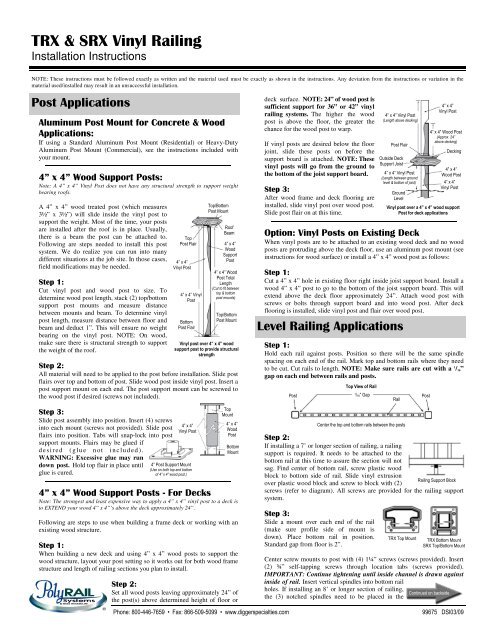
4” x 4” Wood Support Posts - For Decks<br />
Note: The strongest and least expensive way to apply a 4” x 4” vinyl post to a deck is<br />
to EXTEND your wood 4” x 4”’s above the deck approximately 24”.<br />
Following are steps to use when building a frame deck or working with an<br />
existing wood structure.<br />
Step 1:<br />
When building a new deck and using 4” x 4” wood posts to support the<br />
wood structure, layout your post setting so it works out for both wood frame<br />
structure and length <strong>of</strong> railing sections you plan to install.<br />
Step 2:<br />
Set all wood posts leaving approximately 24” <strong>of</strong><br />
the post(s) above determined height <strong>of</strong> floor or<br />
Phone: 800-446-7659 • Fax: 866-509-5099 • www.diggerspecialties.com<br />
deck surface. NOTE: 24” <strong>of</strong> wood post is<br />
sufficient support for 36” or 42” vinyl<br />
railing systems. The higher the wood<br />
post is above the floor, the greater the<br />
chance for the wood post to warp.<br />
If vinyl posts are desired below the floor<br />
joint, slide these posts on before the<br />
support board is attached. NOTE: These<br />
vinyl posts will go from the ground to<br />
the bottom <strong>of</strong> the joist support board.<br />
Step 3:<br />
After wood frame and deck flooring are<br />
installed, slide vinyl post over wood post.<br />
Slide post flair on at this time.<br />
Option: Vinyl Posts on Existing Deck<br />
When vinyl posts are to be attached to an existing wood deck and no wood<br />
posts are protruding above the deck floor, use an aluminum post mount (see<br />
instructions for wood surface) or install a 4” x 4” wood post as follows:<br />
Step 1:<br />
Cut a 4” x 4” hole in existing floor right inside joist support board. Install a<br />
wood 4” x 4” post to go to the bottom <strong>of</strong> the joist support board. This will<br />
extend above the deck floor approximately 24”. Attach wood post with<br />
screws or bolts through support board and into wood post. After deck<br />
flooring is installed, slide vinyl post and flair over wood post.<br />
Level Railing Applications<br />
Step 1:<br />
Hold each rail against posts. Position so there will be the same spindle<br />
spacing on each end <strong>of</strong> the rail. Mark top and bottom rails where they need<br />
to be cut. Cut rails to length. NOTE: Make sure rails are cut with a 1 /16”<br />
gap on each end between rails and posts.<br />
Post<br />
Top View <strong>of</strong> Rail<br />
Step 2:<br />
If installing a 7’ or longer section <strong>of</strong> railing, a railing<br />
support is required. It needs to be attached to the<br />
bottom rail at this time to assure the section will not<br />
sag. Find center <strong>of</strong> bottom rail, screw plastic wood<br />
block to bottom side <strong>of</strong> rail. Slide vinyl extrusion<br />
Railing Support Block<br />
over plastic wood block and screw to block with (2)<br />
screws (refer to diagram). All screws are provided for the railing support<br />
system.<br />
Step 3:<br />
Slide a mount over each end <strong>of</strong> the rail<br />
(make sure pr<strong>of</strong>ile side <strong>of</strong> mount is<br />
down). Place bottom rail in position.<br />
Standard gap from floor is 2”.<br />
4” x 4” Vinyl Post<br />
(Length above decking)<br />
Post Flair<br />
Outside Deck<br />
Support Joist<br />
4” x 4” Vinyl Post<br />
(Length between ground<br />
level & bottom <strong>of</strong> joist)<br />
Ground<br />
Level<br />
4” x 4”<br />
Vinyl Post<br />
4” x 4” Wood Post<br />
(Approx. 24”<br />
above decking)<br />
Decking<br />
4” x 4”<br />
Wood Post<br />
4” x 4”<br />
Vinyl Post<br />
Vinyl post over a 4” x 4” wood support<br />
Post for deck applications<br />
1/16” Gap Post<br />
Rail<br />
Center the top and bottom rails between the posts<br />
TRX Top Mount<br />
TRX Bottom Mount<br />
SRX Top/Bottom Mount<br />
Center screw mounts to post with (4) 1¼” screws (screws provided). Insert<br />
(2) ¾” self-tapping screws through location tabs (screws provided).<br />
IMPORTANT: Continue tightening until inside channel is drawn against<br />
inside <strong>of</strong> rail. Insert vertical spindles into bottom rail<br />
holes. If installing an 8’ or longer section <strong>of</strong> railing,<br />
Continued on backside<br />
the (3) notched spindles need to be placed in the<br />
99675 DSI03/09
TRX & SRX Vinyl Railing<br />
<strong>Installation</strong> <strong>Instructions</strong>...Continued<br />
Level Railing Applications...Continued<br />
middle <strong>of</strong> the section. Position top rail<br />
into spindles one at a time. Position<br />
top rail between posts and fasten top<br />
mounts to post with screws (like<br />
bottom mount procedure).<br />
If using standard height posts, top rail<br />
Assemble Rail Section<br />
should be 2” down (2⅜” down if<br />
using an aluminum post mount) from top <strong>of</strong> post. Should a special height<br />
railing be required, the spindles and post may be cut down.<br />
Place mount covers over mounts. Tap each corner <strong>of</strong> cover to secure it to<br />
mount. CAUTION: For bottom mount cover, line up top two corners <strong>of</strong><br />
cover and LIGHTLY TAP the corners with a hammer. Then, carefully line<br />
up bottom <strong>of</strong> cover and LIGHTLY TAP with a hammer.<br />
Stair Rail Applications<br />
NOTE: Make sure to review level railing applications before these steps are attempted.<br />
Stair rail mounts are needed for stair rail applications. Stair rail mounts are designed<br />
for a 32° to 35° application. Uncut stair rail mounts are available for other angle<br />
applications.<br />
Step 1:<br />
Lay the bottom rail on the<br />
steps and up against the<br />
posts. Determine the two<br />
end holes. Insert a spindle<br />
at each end <strong>of</strong> rail. Place<br />
top rail on top <strong>of</strong> these two<br />
spindles. Holding rails<br />
against posts, determine<br />
exact end spacings, mark<br />
rails for cutting. If<br />
spindles are too tight and<br />
not level, make holes<br />
Equal<br />
Spacing<br />
at Posts<br />
Mark the angle for<br />
cutting bottom<br />
rails<br />
Mark the angle for<br />
cutting top rails<br />
larger by filing out holes accordingly. Then, cut both rails at angle marks.<br />
Cut each end <strong>of</strong> the spindles at the same angle as top and bottom rails were<br />
cut. NOTE: The overall length <strong>of</strong> spindles will not change.<br />
NOTE: Above ground application requires a 48” post at the bottom step.<br />
Field cut after railing is installed. The “A” Series Post must be cut <strong>of</strong>f at the<br />
bottom before railing is installed. “A” Series Post length for bottom <strong>of</strong><br />
steps - 48” for 36” railing and 52” for 42” railing.<br />
Step 2:<br />
Slide a mount over each end <strong>of</strong> the rail (make sure pr<strong>of</strong>ile side <strong>of</strong> mount is<br />
down, remove spacer from bottom mount). Place bottom rail in position.<br />
Center screw mounts to post with (4) 1¼” screws<br />
(screws provided). Insert (2) ¾” self-tapping screws<br />
through location tabs (screws provided). Insert<br />
vertical spindles into bottom rail holes. Position top<br />
rail into spindles one at a time. Position top rail<br />
between posts and fasten top mount to post with<br />
screws (like bottom mount procedure).<br />
If using standard height posts, top rail should be 2”<br />
down from top <strong>of</strong> post. Should a special height<br />
railing be required, the spindles and post may be cut<br />
down.<br />
Equal<br />
Spacing<br />
at Posts<br />
Spindle overall<br />
length remains<br />
the same<br />
TRX Top Stair Mount<br />
TRX Bottom Stair Mount<br />
SRX Top/Bottom Stair Mount<br />
Place mount covers over mounts. Bottom cover has a knock out for a 32° to<br />
35° angle (or may be cut out for varying angles). Tap each corner <strong>of</strong> cover to<br />
secure it to mount. CAUTION: For bottom<br />
mount cover, line up top two corners <strong>of</strong> cover<br />
and LIGHTLY TAP the corners with a<br />
hammer. Then, carefully line up bottom <strong>of</strong><br />
Phone: 800-446-7659 • Fax: 866-509-5099 • www.diggerspecialties.com<br />
cover and LIGHTLY TAP with a hammer.<br />
The top to bottom measurement should be<br />
the same for both the stair rail and the level<br />
rail sections.<br />
Angle Applications<br />
NOTE: Make sure to review the level application installation before these steps are<br />
attempted. Angle mounts are needed for level application. These mounts can be cut to<br />
accept UPTO a 22½° angle. For greater degree angles, the post must be rotated so<br />
both the post and mount will equal the total degree <strong>of</strong> angle. (i.e.: Post 22½° + mount<br />
22½° = total 45° angle.)<br />
Step 1:<br />
Cut rails to correct length, angle to fit in between posts. Make sure it is cut<br />
to be the same spindle spacing at each end <strong>of</strong> the rails. NOTE: These<br />
mounts can be cut to accept UPTO a 22½° angle.<br />
Top<br />
Angle Mount<br />
4” x 4”<br />
Post<br />
Step 2:<br />
Top Mount…<br />
The top mount will need to be cut<br />
at an angle to align with the post<br />
angle. Position top mount on rail to<br />
determine where to cut. Mark<br />
mount and cut on a mitersaw. If needed, use a<br />
belt sander to sand down mount until you get an<br />
exact fit to the post. After mounts fit on post<br />
correctly, slide over each end <strong>of</strong> rail. Refer to<br />
Level Application, Step 3.<br />
45°<br />
Top view <strong>of</strong> angled top rail mounts<br />
Top<br />
Angle Mount<br />
Bottom Mount…<br />
Remove spacer from mount. Turn pr<strong>of</strong>ile toward inside <strong>of</strong> the rail angle.<br />
Center and screw mounts to post with (4) 1¼” screws (screws provided).<br />
Insert (2) ¾” self-tapping screws (screws provided) through location tabs.<br />
Insert vertical spindles into bottom rail holes. If installing 7’ or longer<br />
sections <strong>of</strong> railing, the (3) notched spindles need to be placed in the middle<br />
<strong>of</strong> the section. Position top rail into spindles one a time. Position top rail<br />
between posts and fasten top mounts to post with screws (like bottom mount<br />
procedure).<br />
45° Angle Mount Application<br />
Step 1:<br />
Place a bottom 45° Block on the corners <strong>of</strong> the posts. Cut bottom rail to fit<br />
between blocks. Refer to Level Railing Application, Step 1. Top rail will be<br />
same size as bottom rail if post is level. (Both rails will be cut square.)<br />
Step 2:<br />
Refer to Level Railing Applications to install sections. NOTE: Pilot holes<br />
are required in post. For bottom mounts, drill completely through mounts to<br />
indicate where pilot holes will be.<br />
Post<br />
TRX<br />
Top Mount<br />
TRX<br />
Top Rail<br />
Spindle<br />
Bottom<br />
45° Block<br />
TRX Top Angle Mount<br />
Post<br />
22½°<br />
Spindle<br />
TRX Bottom Mount<br />
SRX Top/Bottom Mount<br />
The top <strong>of</strong> the top rails<br />
and the bottom <strong>of</strong> the<br />
bottom rails should<br />
match in height<br />
Cut or File Cover for<br />
the Desired Angle<br />
TRX Bottom Angle Mount<br />
SRX Top/Bottom Angle Mount<br />
The pr<strong>of</strong>ile edge <strong>of</strong> mount should<br />
be placed to the inside <strong>of</strong> the rail<br />
angle, to hide the rough edge.<br />
TRX Bottom Rail<br />
SRX Top/Bottom Rail<br />
99675 DSI03/09