1 EINLEITUNG - Dr. Neuhaus Telekommunikation GmbH
1 EINLEITUNG - Dr. Neuhaus Telekommunikation GmbH
1 EINLEITUNG - Dr. Neuhaus Telekommunikation GmbH

Create successful ePaper yourself
Turn your PDF publications into a flip-book with our unique Google optimized e-Paper software.
Version:<br />
Date:<br />
4.00<br />
26.10.2012<br />
<strong>Dr</strong>. <strong>Neuhaus</strong> <strong>Telekommunikation</strong> <strong>GmbH</strong><br />
Page 1/27<br />
User Manual<br />
gMUC – Configuration<br />
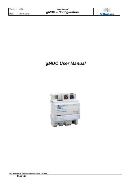
gMUC User Manual
Version:<br />
Date:<br />
Contents<br />
4.00<br />
26.10.2012<br />
<strong>Dr</strong>. <strong>Neuhaus</strong> <strong>Telekommunikation</strong> <strong>GmbH</strong><br />
Page 2/27<br />
User Manual<br />
gMUC – Configuration<br />
1 Introduction .............................................................................................................................................................................. 4<br />
2 Status ...................................................................................................................................................................................... 5<br />
2.1 System ............................................................................................................................................................................. 5<br />
2.2 Meters .............................................................................................................................................................................. 6<br />
2.3 Log ................................................................................................................................................................................... 7<br />
3 Configuration ........................................................................................................................................................................... 8<br />
3.1 System ............................................................................................................................................................................. 8<br />
3.2 WAN ................................................................................................................................................................................. 9<br />
3.3 LAN ................................................................................................................................................................................ 13<br />
3.4 Update ............................................................................................................................................................................ 13<br />
3.4.1 Uploading the firmware ........................................................................................................................................... 13<br />
3.4.2 Activating the firmware ............................................................................................................................................ 14<br />
3.5 Meter .............................................................................................................................................................................. 14<br />
3.5.1 Special Notes for the configuration of a MBUS meter ............................................................................................. 15<br />
3.6 Interfaces ........................................................................................................................................................................ 17<br />
3.7 MODBUS ........................................................................................................................................................................ 18<br />
3.8 Learn-Mode .................................................................................................................................................................... 18<br />
4 Security .................................................................................................................................................................................. 22<br />
5 Formation rules for W-MBUS address ................................................................................................................................... 22<br />
6 OBIS Mapping ....................................................................................................................................................................... 23<br />
7 Push ...................................................................................................................................................................................... 24<br />
8 Appendix ................................................................................................................................................................................ 26<br />
8.1 List of abbreviations ........................................................................................................................................................ 26<br />
9 Copyright Statement .............................................................................................................................................................. 27
Version:<br />
Date:<br />
4.00<br />
26.10.2012<br />
List of changes since the last version<br />
<strong>Dr</strong>. <strong>Neuhaus</strong> <strong>Telekommunikation</strong> <strong>GmbH</strong><br />
Page 3/27<br />
User Manual<br />
gMUC – Configuration<br />
Version Date Who Chapter Changes since the last version<br />
1.00 20.07.2010 HKE Created<br />
2.00 30.08.2010 HKE - RS232 Interface support<br />
- DynDNS configuration / Examples<br />
- STUN interval<br />
08.03.2011 JSC Details Learn mode<br />
3.00 02.09.2011 HKE Push<br />
19.09.2011 JSC Details Learn mode<br />
01.10.2011 JSC 3.6 Details Interface configuration<br />
3.10 11.11.2011 HKE 3.7 MODBUS support<br />
3.21 12.03.2012 RGR - support wMBus Mode S<br />
- check WAN connectivity (Ping)<br />
23.10.2012 RGR 3.5 gMUC v2 M-Bus Configuration
Version:<br />
Date:<br />
4.00<br />
26.10.2012<br />
1 INTRODUCTION<br />
<strong>Dr</strong>. <strong>Neuhaus</strong> <strong>Telekommunikation</strong> <strong>GmbH</strong><br />
Page 4/27<br />
User Manual<br />
gMUC – Configuration<br />
This manual explains the options for configuring a gMUC. The parameters for the gMUC are set using a web configuration. You<br />
require the use of a browser (e.g. Internet Explorer). A secure connection (https) to the configuration interface is set up in the<br />
address bar in the browser. The default IP address is set to 192.168.186.10. The username is admin, the password is admin.<br />
� (i.e. https://192.168.168.10).<br />
Once you have registered, the following start screen will appear:<br />
Figure 1: Start screen<br />
The start screen shows the explicit gMUC ID and the existing hardware options for the gMUC. All external interfaces are labeled<br />
on the illustration.<br />
At the top edge of the screen, you will find the configuration menu, which will be explained in more detail in the following. The<br />
chapters after that are based on the menu structure. The entire web configuration was created in English.
Version:<br />
Date:<br />
4.00<br />
2 STATUS<br />
26.10.2012<br />
<strong>Dr</strong>. <strong>Neuhaus</strong> <strong>Telekommunikation</strong> <strong>GmbH</strong><br />
Page 5/27<br />
User Manual<br />
gMUC – Configuration<br />
The Status section provides information on the current status of the gMUC. It cannot be altered 1 . The information available<br />
includes status variables, the meters available and the log.<br />
2.1 System<br />
This indicates the internal status variables that are currently set in the system. These are system-specific and service-specific<br />
variables the number of which depends on the operating mode used (GPRS, DSL) and the hardware.<br />
Figure 2: Status - System<br />
1 To alter the parameters, see Chap. 3
Version:<br />
Date:<br />
4.00<br />
2.2 Meters<br />
26.10.2012<br />
<strong>Dr</strong>. <strong>Neuhaus</strong> <strong>Telekommunikation</strong> <strong>GmbH</strong><br />
Page 6/27<br />
User Manual<br />
gMUC – Configuration<br />
This screen shows a list of the available meters. Further details on the meter are also shown for each entry (address, measured<br />
variables, etc.).<br />
Before the values from one of the meters are recorded by the gMUC, that meter has to be activated – to do so, click the button<br />
marked ‘Activate”, which appears if the meter is not yet registered in the gMUC.<br />
For W-MBUS meters, the W-MBUS identifiers are mapped on standardized OBIS numbers in the gMUC. If this mapping<br />
process is incomplete or defective for a meter, this will be displayed on the screen. The mapping then has to be adjusted<br />
accordingly in the gMUC. If the meter data received from a W-MBUS meter is encrypted, the meter must first be activated (click<br />
‘Activate’), and then store the corresponding AES key in the configuration of the meter (Chapter 3.5).<br />
Figure 3: Status - Meter
Version:<br />
Date:<br />
2.3 Log<br />
4.00<br />
26.10.2012<br />
<strong>Dr</strong>. <strong>Neuhaus</strong> <strong>Telekommunikation</strong> <strong>GmbH</strong><br />
Page 7/27<br />
User Manual<br />
gMUC – Configuration<br />
The operating events generated in the system are stored in a log, which can be read out on this screen. Among other things, it<br />
provides information on any errors that have occurred and system messages. Click the button marked ‘Delete’ to permanently<br />
delete the information currently in the log.<br />
Figure 4: Status - Log
Version:<br />
Date:<br />
4.00<br />
26.10.2012<br />
3 CONFIGURATION<br />
<strong>Dr</strong>. <strong>Neuhaus</strong> <strong>Telekommunikation</strong> <strong>GmbH</strong><br />
Page 8/27<br />
User Manual<br />
gMUC – Configuration<br />
The section on Configuration explains how to configure the parameters for the gMUC.<br />
3.1 System<br />
The System screen can be used to alter the registration information (username / password) for the web configuration. The<br />
gMUC system time (UTC) is set here and you can also trigger a restart of the gMUC.<br />
Figure 5: Configuration – System<br />
WebUI access configured the client authentication (HTTP Digest) for the WAN interface. If no user/password assigned, the<br />
client side authentication is disabled.<br />
With the button "Restart", a system reboot will be initiated gMUC<br />
In the section "System Time", the system time of the gMUC can be called/changed. If the time is synchronized by a NTP time<br />
server, the field is disabled. The value "local offset" indicates the time offset of the current time zone in which the gMUC is in<br />
hours (time difference from UTC). The automatic use (switching) from summer / winter time can also be switched on / off.
Version:<br />
Date:<br />
3.2 WAN<br />
4.00<br />
26.10.2012<br />
<strong>Dr</strong>. <strong>Neuhaus</strong> <strong>Telekommunikation</strong> <strong>GmbH</strong><br />
Page 9/27<br />
User Manual<br />
gMUC – Configuration<br />
This screen is used to configure the WAN (Wide Area Network) interface for the gMUC. Before you can use the WAN interface,<br />
it has to be activated. The WAN interface is always the rear Ethernet RJ45 jack on the gMUC.<br />
The following general parameters are available:<br />
� Max WAN connection delay<br />
- Maximum connection delay to start the WAN interface in seconds<br />
- In this way, the load can be distributed during a startup for the operation of a large number of gMUCs.<br />
� gMUC ID<br />
- The ID of the individual gMUC to differentiate between the different devices<br />
- If the gMUC ID is left blank (default), the MAC address in Hex notation without the dots will be used automatically as<br />
the ID<br />
� WAN restart period<br />
- Time in seconds after which the WAN interface is restarted cyclically (default: 0 = off)<br />
There are four different ways in which the device can be reached via WAN:<br />
� IP, PPPoE, DHCP and GPRS.
Version:<br />
Date:<br />
4.00<br />
26.10.2012<br />
Figure 6: Configuration – WAN<br />
<strong>Dr</strong>. <strong>Neuhaus</strong> <strong>Telekommunikation</strong> <strong>GmbH</strong><br />
Page 10/27<br />
User Manual<br />
gMUC – Configuration<br />
� IP<br />
- In this case, the gMUC can be given a fixed static IP address, at which it can be reached in the WAN network<br />
(e.g. Internet/Intranet).<br />
- As a rule, this configuration is used for testing only.<br />
� PPPoE<br />
- This option is used to configure a PPPoE dial-up onto the Internet using DSL technologies.<br />
- The username and the password for DSL access must be stored here.<br />
- The gMUC must be connected to a DSL modem with its WAN interface.<br />
� DHCP<br />
- In this operating mode, the gMUC is operated on an existing DSL router.<br />
- The router performs the DSL dial-up itself and has to be configured as the DHCP server.<br />
- The gMUC then serves as the NAT client “behind” the router and gets its IP parameters (IP address, DNS, etc.) via the<br />
DHCP protocol from this router.<br />
- It is not necessary to configure special parameters in the gMUC.<br />
- The gMUC must be connected to the router with its WAN interface.<br />
� GPRS<br />
- This option is used for the configuration of a GPRS dial-up on the Internet.<br />
- The gMUC must have a valid SIM card; the SIM-card parameters (PIN, username, password) must be configured<br />
accordingly.<br />
- The network operator’s APN (Access Point Name) also has to be entered.<br />
Other general configurations are optional …<br />
� STUN<br />
- If a STUN server is configured, the public IP address of the DSL connection can be identified.<br />
- This is useful in the DHCP operating mode in particular, in which case the public IP address of the DSL router is<br />
required. A time interval can be configured (in seconds) where he periodically STUN server is queried, which is<br />
necessary if the public Internet can change address (forced separation in DSL access)<br />
� DNS<br />
- This is where you can configure a static DNS server for an Internet name resolution.<br />
- As a rule, this only makes sense in the IP operating mode because the DNS server is configured automatically in the<br />
system in all the other cases (PPPoE, DHCP, GPRS).
Version:<br />
Date:<br />
4.00<br />
26.10.2012<br />
<strong>Dr</strong>. <strong>Neuhaus</strong> <strong>Telekommunikation</strong> <strong>GmbH</strong><br />
Page 11/27<br />
User Manual<br />
gMUC – Configuration<br />
� DynDNS<br />
- This is where you can configure a DynDNS Internet service.<br />
- This makes it possible to address the gMUC under a fixed symbolic, non-ambiguous name on the Internet instead of<br />
using the device’s IP address, which can change under certain circumstances (e.g. new Internet dial-up).<br />
- The configuration parameters depend individually on the DynDNS service used.<br />
- The following placeholders are available to define a DynDNS update request in general:<br />
- The update request cannot contain any "".<br />
Placeholders Meaning<br />
DynDNS username<br />
DynDNS password<br />
gMUC ID<br />
DynDNS domain<br />
Public Internet IP address (e.g. assigned via PPPoE or STUN)<br />
or Local IP address (e.g. assigned via fixed IP4 or DHCP)<br />
Example of registration with the “dyndns.com“ provider<br />
username,password:<br />
bba@neuhaus.de,technik12345<br />
domain:<br />
gmuc.dnsalias.org<br />
update request:<br />
-u : -a -h -S dyndns<br />
Example of registration with the “no-ip.com“ provider<br />
username,password:<br />
bba@neuhaus.de,technik12345<br />
domain:<br />
002569627165.no-ip.org<br />
update request:<br />
-u : -a -h -s dynupdate.no-ip.com -S dyndns -g<br />
/nic/update?username=&password=&hostname=&myip=<br />
� Ping<br />
- to check the IP connectivity, servers can be configured to be pinged at configurable intervals<br />
- up to three servers are adjustable<br />
- interval defines the period in seconds, a server is pinged<br />
- length defines the length of the payload<br />
- repeat defines the number of retries after an unsuccessful ping attempt<br />
- after timeout seconds a ping request have to be acknowledged<br />
- after Retrying repeat +1 times on every configured server the WAN connection will be restarted<br />
- the WAN restart period is random between 1 s and 60 s<br />
- a repeating disconnect of the WAN connection because of an unsuccessful ping session results in doubling the<br />
WAN restart period<br />
- once the WAN restart period is higher than 3600 s, the increasing is stopped<br />
� NTP<br />
- The NTP protocol is used to synchronize the gMUC time.<br />
- It is possible to enter the NTP server and the interval, in which a synchronization process takes place.<br />
- As a rule, the gMUC uses UTC (Universal Time Coordinated) time internally.<br />
Remark<br />
In the Group 'NTP', the NTP servers are specified, and the interval at which a synchronization is performed.<br />
The set NTP period cannot be set exactly to any second, but only on powers of two.<br />
2 4 = 16, 2 5 = 32, 2 6 = 64, 2 7 = 128, 2 8 = 256, 2 9 = 512, 2 10 = 1024, 2 11 = 2048<br />
, 2 12 = 4096 ... 2 17<br />
The gMUC completes the calculated power, i.e. be set to 2048 sec 3600 sec (34min). The next highest value is 4096 seconds<br />
(68 min). The maximum value is 2 17 seconds. If it is determined that the system time is stable, the round trip time is
Version:<br />
Date:<br />
4.00<br />
26.10.2012<br />
<strong>Dr</strong>. <strong>Neuhaus</strong> <strong>Telekommunikation</strong> <strong>GmbH</strong><br />
Page 12/27<br />
User Manual<br />
gMUC – Configuration<br />
automatically increased by the NTP service � NTP standard algorithm. The NTP service regulates the system clock and<br />
ensures that no time jumps occur due to the synchronization!
Version:<br />
Date:<br />
3.3 LAN<br />
4.00<br />
26.10.2012<br />
<strong>Dr</strong>. <strong>Neuhaus</strong> <strong>Telekommunikation</strong> <strong>GmbH</strong><br />
Page 13/27<br />
User Manual<br />
gMUC – Configuration<br />
This screen is used to configure the data for the service interface (front Ethernet interface). The IP address and the network<br />
mask can be configured. The service interface is a prerequisite for web access. The default setting for the IP address is<br />
configured to 192.168.168.10.<br />
Figure 7: Configuration – LAN<br />
3.4 Update<br />
Updates are available for the firmware on the gMUC. This is done in two steps:<br />
Upload and activate the firmware. The firmware versions already loaded onto the device will also appear on the list. A total of up<br />
to three different firmware versions can be stored on the device.<br />
The firmware version that initially comes with the device cannot be overwritten or deleted. The user can choose from between<br />
two versions by activating the desired version.<br />
Figure 8: Configuration - Update<br />
3.4.1 Uploading the firmware<br />
To upload a new firmware program onto the device, you must select a firmware file delivered by the manufacturer on the input<br />
screen. Once the file has been selected, the upload process must be started.<br />
Once the upload has been successfully completed, the new firmware version will appear on the list of firmware versions. Should<br />
an error occur, an error message will appear on the screen.<br />
The firmware that was uploaded is now available on the device and ready for activation.<br />
Up to two individual firmware files can be uploaded.
Version:<br />
Date:<br />
4.00<br />
26.10.2012<br />
3.4.2 Activating the firmware<br />
<strong>Dr</strong>. <strong>Neuhaus</strong> <strong>Telekommunikation</strong> <strong>GmbH</strong><br />
Page 14/27<br />
User Manual<br />
gMUC – Configuration<br />
After the new firmware has been uploaded, it is still inactive – the previous version is the one that is active.<br />
If you want to activate the new firmware, you have to click the corresponding ‘Activate’ button in the list to replace the previous<br />
version with the newly activated one. The system will be restarted automatically.<br />
This completes the activation process. The previous version of the firmware will remained stored on the device and can be<br />
reactivated at any time.<br />
Only one version of the firmware can be active at any one time. Once the firmware has been activated, the gMUC will not be<br />
available again until the restart has been completed.<br />
3.5 Meter<br />
This is the screen you use to add meters and to configure meters that have already been activated (cf. Chap. 2.2).<br />
The following information must be provided for new meters only:<br />
� the identification of the meter (meter ID)<br />
� the medium recorded (short form)<br />
� the manufacturer (short form)<br />
� configuration parameters (interface, protocol, technical bus-address, special interface parameter)<br />
The following information can also be included for new and existing meters:<br />
� the interface via which the meter can be reached<br />
� a key for the secure connection to the meter (optionally in Hex notation e.g. 01.02.03……..)<br />
� one or more loggers, which describe the measurements recorded<br />
Several loggers can be added to a meter, configured and also removed from the meter. The following values must be entered<br />
for a logger:<br />
- the logger name (the following are already predefined: 15m, 1d, 1h, 1m, 1mon)<br />
- the logger time interval (the following are defined: MINUTE, 15 MINUTE, HOUR, DAY, WEEK, MONTH, YEAR)<br />
- the max. size (number of entries) for the logger<br />
- the OBIS ID for the measurement to be recorded<br />
The following parameters are valid for options:<br />
Interface name: RS485, RS232, WMBUS<br />
Protocol: 1107, SML, MBUS, DLMS, MODBUS<br />
Baudrate: Baudrate=300[,600,1200,2400,9600,19200,38400,57600,115200]<br />
Time source: NTP,meter<br />
ADDR: xxxxxx (e.g. RS485 bus address, WMBUS-MeterID, MODBUS address)<br />
Example: RS485,1107,Baudrate=300,NTP,ADDR=00000001<br />
Example: WMBUS,MBUS,ADDR=38000226<br />
Example: RS232,SML,Baud rate=9600,meter,ADDR=01A815671833020102<br />
Example: RS485,DLMS,Baudrate=115200,NTP,Hdlc=100.17.1,Password=12345678<br />
Example: RS485,MODBUS,ADDR=2,Baudrate=9600,Register0=HR:0:uint16,Register1=HR:1:uint16
Version:<br />
Date:<br />
4.00<br />
26.10.2012<br />
Figure 9: Configuration – Meter<br />
<strong>Dr</strong>. <strong>Neuhaus</strong> <strong>Telekommunikation</strong> <strong>GmbH</strong><br />
Page 15/27<br />
User Manual<br />
gMUC – Configuration<br />
3.5.1 Special Notes for the configuration of a MBUS meter<br />
The protocol MBUS requires MUS V2 and additional hardware.<br />
The MBUS specification defines two types of addressing a meter. primary addressing an d secondary addressing. Most meters<br />
support both types. MUS V2 supports only secondary addressing.<br />
To configure MBUS meter the secondary address (4 bytes – BCD encoded) have to be specified in parameter ADDR.<br />
The secondary address corresponds to the serial number printed on the meter. Leading zeros have to be filled up to a size of 8<br />
digits. When using secondary addressing the following three parameters have to be correct: secondary address, medium, meter<br />
software version (0-255).<br />
In case of unknown parameter, placeholder can be used.<br />
- secondary address: FFFFFFFF<br />
- medium: X (intern 0xFF)<br />
- meter software version: keep empty or 255 (decimal representation)<br />
Every meter responses, whose own parameters matches with configured ones.<br />
For example, a meter with the data<br />
� secondary address: 2547659<br />
� baud rate: 2400<br />
� meter software version: 0<br />
� number of responses: 1<br />
is configured as followed:
Version:<br />
Date:<br />
4.00<br />
26.10.2012<br />
<strong>Dr</strong>. <strong>Neuhaus</strong> <strong>Telekommunikation</strong> <strong>GmbH</strong><br />
Page 16/27<br />
User Manual<br />
gMUC – Configuration<br />
Some meters responses with more than one messages. To get additional responses the optional parameter Responses have to<br />
configured. The default setting is Responses=1. The number of responses a meter provided, can be found in the datasheet.<br />
Commands send to a meter, will not be responded in the same way for different meters. The optional parameter OPTIONS<br />
handle those deviations.<br />
OPTIONS value definition<br />
01 Meters do not response on an init command (i.e. Carlo<br />
Gavazzi Controls (EM33-DIN)).<br />
With OPTIONS=01 such meters are requested correctly.<br />
02 Some Meters responses with large data packets (i. e.<br />
Landis+Gyr (UH50-A38C-DE00-B)) A configured baud rate<br />
less than 2400 baud results in a timeout.<br />
With OPTIONS=02 the timeout is increased for the specific<br />
meter.<br />
The Elster MBUS PR6 meter responds to the command SND_NKE whether this meter has been addressed or not. Meters that<br />
can provide more than one responses, require the command SND_NKE. Consequently the simultaneous operation of a meter,<br />
that provides more than one response, and the PR6 module does not work reliably. Alternatively, meters have to be configured<br />
with Responses=1 to work in combination with a PR6 module.
Version:<br />
Date:<br />
4.00<br />
26.10.2012<br />
3.6 Interfaces<br />
<strong>Dr</strong>. <strong>Neuhaus</strong> <strong>Telekommunikation</strong> <strong>GmbH</strong><br />
Page 17/27<br />
User Manual<br />
gMUC – Configuration<br />
The Interfaces screen lists the meter interfaces available on (RS485 / WMBUS 2 ). Additional options can be indicated for each of<br />
these interfaces.<br />
Figure 10: Configuration - Interfaces<br />
The options provided for an interface must be separated from each other by commas.<br />
Possible options include:<br />
Interface type Option Meaning<br />
RS485<br />
RS232<br />
Learn=1107<br />
Learn=SML<br />
Learn=DLMS<br />
Automatic recognition of inactive meters with indication of the<br />
protocol:<br />
1107 = Recognition of 1107 meters on the RS485<br />
SML = Recognition of SML meters on the RS485<br />
DLMS = Recognition of DLMS meters on the RS485<br />
Baud rate=xx Speed of the interface in baud in Learn Mode; for 1107 meters,<br />
this is the starting baud rate (300, 1200, 2400,….)<br />
Query=xx Query interval in seconds (only multiples of 60 seconds allowed)<br />
Password=xx Password (ASCII) when using DLMS meter<br />
Hdlc=xx.yy.zz HDLC address when using DLMS meter (default 100.17.1)<br />
Mode= D = mode D when using 1107 meter<br />
C = mode C when using 1107 meter (default)<br />
Ciase = when using Sagem/DLMS meter<br />
Password= Meter password when using DLMS meter<br />
Register0..n= Dataregister definition when using MODBUS sensor<br />
WMBUS Learn Automatic recognition of inactive WMBUS meters<br />
The protocol (MBUS or SML) of the payload is automatically<br />
recognized by the WMBUS and does not have to be entered.<br />
Mode= T = wMBus module works in T-Mode (default)<br />
S = wMBus module works in S-Mode<br />
MBUS Baudrate=xx Speed of the interface in baud (300,600,1200,2400,4800,9600)<br />
Responses=xx Number of MBus responses on a meter request<br />
default: Responses=1<br />
OPTIONS=xx optional MBus parameter to control protocol exceptions<br />
2 Wireless M-Bus
Version:<br />
Date:<br />
4.00<br />
26.10.2012<br />
Example configurations<br />
<strong>Dr</strong>. <strong>Neuhaus</strong> <strong>Telekommunikation</strong> <strong>GmbH</strong><br />
Page 18/27<br />
User Manual<br />
gMUC – Configuration<br />
meter typ meter options Interface options<br />
1107 to RS485 RS485,1107,ADDR=12345678,Baudrate=9600,Mode=C Query=60<br />
SML to RS232 RS232,SML,ADDR=12345678,Baudrate=9600<br />
DLMS to RS485 RS485,DLMS,ADDR=12345678,Hdlc=100.17.1,Baudrate=115200,Password=xxxxx Query=60<br />
DLMS/Sagem an<br />
RS485<br />
(with Discovery)<br />
RS485,DLMS,ADDR=12345678,Mode=Ciase,Baudrate=9600,Password=xxxx,<br />
Hdlc=100.17.1<br />
WMBUS WMBUS,MBUS,ADDR=12345678<br />
MODBUS to RS485 RS485,MODBUS,ADDR=1,Baudrate=19200,<br />
Register0=IR:0:floatinverse, Register1=IR:2:floatinverse<br />
3.7 MODBUS<br />
The query of certains registers of a MODBUS sensor must be configured in the meter options using the parameters<br />
Register0..n=function:address:format:<br />
- Query function (HR - holding register, IR - input register)<br />
- Register start-adress (integer)<br />
- Register data format (uint16, uint32, float, floatinverse)<br />
Syntax: Register[0..n]=function[HR,IR]:adress:format<br />
Example: Register0=HR:0:uint16, Query of the holding register with start adresse 0, data format integer<br />
Example: Register1=IR:2:floatinverse, Query of the input register with start adresse 2, data format floatinverse<br />
complete meter options for the query of two registers:<br />
RS485,MODBUS,ADDR=1,Baudrate=19200,Register0=IR:0:floatinverse,Register1=IR:2:floatinverse<br />
The registers must be mapped in the OIDMAP (chapter 6) to the Obis numbering system.<br />
3.8 Learn-Mode<br />
Query=60<br />
Query=60<br />
The learn mode is used for automatic detection of not activated meters. Notice the following facts when using the learn mode:<br />
1107<br />
While the learn mode is active only one meter should be connected via RS485, otherwise there will be collisions on the bus and<br />
no data can be read out. This meter will be requested with an ‚empty’ address. If the answer contains the real address it will be<br />
read out.
Version:<br />
Date:<br />
4.00<br />
26.10.2012<br />
<strong>Dr</strong>. <strong>Neuhaus</strong> <strong>Telekommunikation</strong> <strong>GmbH</strong><br />
Page 19/27<br />
User Manual<br />
gMUC – Configuration<br />
After detection of the meter, the learn mode has to be switched off.<br />
Some 1107 meters do not support this type of request (empty address). In this case the meter has to be added manually.<br />
DLMS<br />
The DLMS meters of the manufacturer Sagem use a further protocol (CIASE). With this protocol the Sagem DLMS meters<br />
connected to the RS485 are detected. While detection, the meters recieve an MAC address, i.e. the learn mode is necessary for<br />
the first start. To ensure this, add Learn=DLMS to the interface configuration (s. Figure 10). After a successful<br />
detection/activation of the new Sagem meter, the learn mode option has to be removed from the interface configuration.<br />
The learn mode is also activated automatically on faulty DLMS requests and manually meter configuration for a short time.
Version:<br />
Date:<br />
4.00<br />
26.10.2012<br />
<strong>Dr</strong>. <strong>Neuhaus</strong> <strong>Telekommunikation</strong> <strong>GmbH</strong><br />
Page 20/27<br />
User Manual<br />
gMUC – Configuration<br />
The whole chain of the detection is described here:<br />
1. Connection of the Sagem meter(s) over the RS485 interface<br />
2. activation of the learn mode in the interface configuration (s. Figure 10)<br />
3. wait for the detection of the new meter, check by refreshing the page Status – Meter, e. g.:<br />
Figure 11: detected Sagem DLMS meter<br />
The learn mode is now automatically deactivated<br />
4. Activation of the new meter and adjustment of the logger on the page Configuration – Meter<br />
Figure 12: configuration of the new Sagem DLMS meter<br />
the follwing OBIS-Ids are available:<br />
� Power: 1-0:1.6.0<br />
� Energy: 1-0:1.8.0
Version:<br />
Date:<br />
4.00<br />
26.10.2012<br />
<strong>Dr</strong>. <strong>Neuhaus</strong> <strong>Telekommunikation</strong> <strong>GmbH</strong><br />
Page 21/27<br />
User Manual<br />
gMUC – Configuration<br />
5. After the next request of the meter ist values are shown on the page STATUS\meter:<br />
Figure 13: values of the new Sagem DLMS meter<br />
6. deactivation of the learn mode in the interface configuration (s. Figure 10) by removing the option Learn=DLMS
Version:<br />
Date:<br />
4.00<br />
4 SECURITY<br />
26.10.2012<br />
<strong>Dr</strong>. <strong>Neuhaus</strong> <strong>Telekommunikation</strong> <strong>GmbH</strong><br />
Page 22/27<br />
User Manual<br />
gMUC – Configuration<br />
For safety reasons, there is an active firewall on the gMUC that routes only the following IP ports:<br />
� 80 (http)<br />
� 443 (https)<br />
� 22 (SSH, SFTP)<br />
This means, for example, that a gMUC does not respond to an ICMP (ping) query.<br />
5 FORMATION RULES FOR W-MBUS ADDRESS<br />
The meter address is read directly on the meter and used for the configuration. It must consist of 8 digits. If the address is<br />
shorter, it must be preceded by the corresponding number of zeros. The internal W-MBUS address is created on the basis of<br />
the medium/manufacturer/meter ID.<br />
Example: 01.2D.2C.11.78.67.14.01.02 (internal WMBUS address)<br />
Corresponds to: E/KAM/14677811
Version:<br />
Date:<br />
4.00<br />
26.10.2012<br />
6 OBIS MAPPING<br />
<strong>Dr</strong>. <strong>Neuhaus</strong> <strong>Telekommunikation</strong> <strong>GmbH</strong><br />
Page 23/27<br />
User Manual<br />
gMUC – Configuration<br />
Inside the gMUC all meter data will be managed by a number OBIS number. This numbering system is for example in WMBUS<br />
protocol and MODBUS not supported. The DLMS protocol need additional parameters (attributes and class), that must be<br />
configured for a meter data query.<br />
The mapping is done by specifying the protocol (protocol=mbus,dlms,modbus) and by special protocol parameters that lead to<br />
compliance with OBIS mapping to the specified OBIS number/name. When mapping, the unit (unit) and scaling (scale) of the<br />
measured value can be specified. The scaler is using the formula: value = value * 10 scaler applied to the measured value.<br />
Mapping of a WMBUS meter:<br />
For a OBIS number/name the corresponding Dif, Vif, parameters of the WMBUS protocol must be configured. These are<br />
specified in hexadecimal notation. e.g. dif=07,vif=03.3B By configuration of optional parameter „medium=“ and/or<br />
„meteraddr=“ it is possible to specify the mapping for an specific medium or meter.<br />
Mapping of a DLMS meter:<br />
For a OBIS number/name the corresponding class and attribute of the DLMS protocol must be configured.<br />
e.g. class=0003, attribute=02.03<br />
Mapping of a MODBUS Sensor:<br />
For a OBIS number/name the corresponding bus-address of the sensor and the MODBUS register with specification of function<br />
(HR - holding register, IR - input register) and start address must be configured. e.g. meteraddr=1,register=HR:2
Version:<br />
Date:<br />
7 PUSH<br />
4.00<br />
26.10.2012<br />
<strong>Dr</strong>. <strong>Neuhaus</strong> <strong>Telekommunikation</strong> <strong>GmbH</strong><br />
Page 24/27<br />
User Manual<br />
gMUC – Configuration<br />
The Push page configured the Push jobs of the gMUC. The Push feature will be periodically sent meter data from the gMUC to<br />
an FTP or HTTP server. The transmitted data is sent in XML structures. Using FTP Push, a XML file will be sent to the FTP<br />
server. Using HTTP Push, the same XML data will be sent as content of the html file. The push XML data structures are<br />
described in the document gMUC_XML_Interface_vEN.doc.<br />
Configuration of an push target:<br />
NAME symbolic name of the PUSH target, using for referencing on meter configuration<br />
ON global activation/deactivation of the Push target<br />
HOST DNS-Name or IP- address of the Push servers with port number<br />
PROTOCOLL FTP or HTTP<br />
USER/PASSWORD Client authentication of the Push server (optional)<br />
ENTRY COUNT Maximum number of measurements in one push packet, this value determines the max.<br />
XML file size of a single push.<br />
MAX. RUNTIME Push Timeout in seconds
Version:<br />
Date:<br />
4.00<br />
26.10.2012<br />
<strong>Dr</strong>. <strong>Neuhaus</strong> <strong>Telekommunikation</strong> <strong>GmbH</strong><br />
Page 25/27<br />
User Manual<br />
gMUC – Configuration<br />
For the configuration of the URI (FTP file name, HTTP query string) wildcards are available with which one can realize a<br />
dynamic run-time implementation. The configuration of the URI is optional and must be coordinated with the server. When you<br />
push the FTP directory, the structure of the given file name on the server is automatically created.<br />
gMUC: Device ID / name<br />
Meter: medium / manufacturer / address / ID<br />
Data Logger Profile (1m, 15m, 1h, 1d, 1mon)<br />
Push time: second / Text<br />
In the meter configuration, each logger profile will be assigned to a push job. Is this configured, the meter data of this logger will<br />
be pushed to the corresponding push target. The push interval of a logger can be configured individually. It need not be identical<br />
to the recording interval (period). E.g. In the example below, the 15 minute values are pushed all hours. In the corresponding<br />
XML files you will find 4 data points.<br />
The Push of every meter can be enabled / disabled � loggers across. It is also possible to enable/disable the push for every<br />
single logger (check box).<br />
If the checkbox RAW enabled, the raw protocol data (undecoded) received from the meter will be append to the XML data<br />
structures.<br />
Push logger configuration of a meter<br />
Comment:<br />
When using the FTP protocol (http://en.wikipedia.org/wiki/Ftp), the passive mode is used. The EPSV command will be used for<br />
that. The gMUC initiated all TCP-connections to the FTP Server.
Version:<br />
Date:<br />
4.00<br />
8 APPENDIX<br />
26.10.2012<br />
8.1 List of abbreviations<br />
Abbreviation Meaning<br />
APN Access Point Name<br />
<strong>Dr</strong>. <strong>Neuhaus</strong> <strong>Telekommunikation</strong> <strong>GmbH</strong><br />
Page 26/27<br />
User Manual<br />
gMUC – Configuration<br />
DHCP Dynamic Host Configuration Protocol<br />
DLMS Device Language Message Specification<br />
DNS Domain Name System<br />
DynDNS/DDNS dynamic Domain-Name-System<br />
GPRS General Packet Radio Service<br />
GSM Global System for Mobile Communications<br />
IP Internet Protocol<br />
LAN Local Area Network<br />
gMUC Multi Utility Gateway<br />
NAT Network Address Translation<br />
NTP Network Time Protocol<br />
PIN Personal Identification Number<br />
PPPoE Point-to-Point Protocol over Ethernet<br />
SIM Subscriber Identity Module<br />
STUN Session Traversal Utilities for NAT<br />
WAN Wide Area Network<br />
MBUS / M-Bus wired Meter Bus<br />
WMBUS / wMBUS wireless Meter Bus
Version:<br />
Date:<br />
4.00<br />
26.10.2012<br />
9 COPYRIGHT STATEMENT<br />
<strong>Dr</strong>. <strong>Neuhaus</strong> <strong>Telekommunikation</strong> <strong>GmbH</strong><br />
Page 27/27<br />
User Manual<br />
gMUC – Configuration<br />
The information released in this publication is under copyright. Any translation, reprints, duplication and/or storage in dataprocessing<br />
systems requires the express consent of <strong>Dr</strong>. <strong>Neuhaus</strong> <strong>Telekommunikation</strong> <strong>GmbH</strong>.<br />
© 2010 <strong>Dr</strong>. <strong>Neuhaus</strong> <strong>Telekommunikation</strong> <strong>GmbH</strong><br />
All rights reserved.<br />
<strong>Dr</strong>. <strong>Neuhaus</strong> <strong>Telekommunikation</strong> <strong>GmbH</strong><br />
Papenreye 65<br />
D-22453 Hamburg<br />
Germany<br />
Internet: http://www.neuhaus.de<br />
Subject to technical modification<br />
gMUC is a trademark of <strong>Dr</strong>. <strong>Neuhaus</strong> <strong>Telekommunikation</strong> <strong>GmbH</strong>. All other trademarks and product names are the trademarks,<br />
registered trademarks or product names of the respective owners.<br />
<strong>Dr</strong>. <strong>Neuhaus</strong> <strong>Telekommunikation</strong> <strong>GmbH</strong> renders all deliveries and services on the basis of the currently valid version of the<br />
company’s General Conditions of Contract. All information is provided on the basis of the manufacturer’s information. No<br />
warranty or liability for any incorrect information and omissions. The description of the specifications in this manual does not<br />
constitute a contract.<br />
Doc. No.: 8190AD010 / Version 4.0