General-Purpose AC Servo MELSERVO-J2-Super New Product News
General-Purpose AC Servo MELSERVO-J2-Super New Product News
General-Purpose AC Servo MELSERVO-J2-Super New Product News

Create successful ePaper yourself
Turn your PDF publications into a flip-book with our unique Google optimized e-Paper software.
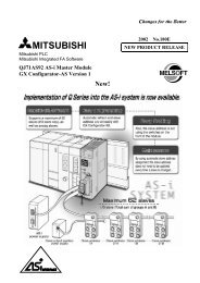
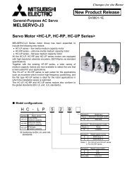
<strong>General</strong>-<strong>Purpose</strong> <strong>AC</strong> <strong>Servo</strong><br />
<strong>MELSERVO</strong>-<strong>J2</strong>-<strong>Super</strong><br />
<strong>AC</strong> <strong>Servo</strong> Amplifier with Built-in Program Operation Functions<br />
MR-<strong>J2</strong>S-CL Type Unveiled!!<br />
The new MR-<strong>J2</strong>S-CL now offers built in motion programming to<br />
compliment the advanced features of the MR-<strong>J2</strong>S series servo<br />
amplifiers.<br />
The MR-<strong>J2</strong>S-CL enables single axis positioning using a<br />
straightforward programming language.<br />
Programmable motion profiles are achieved using the<br />
comprehensive instruction set to define target position, speed,<br />
acceleration, deceleration and more.<br />
Program flexibility is also possible using external interrupts,<br />
latches, and pulse counters as well as looping instructions.<br />
The MR-<strong>J2</strong>S- CL is ideal for single axis motion application or can<br />
be networked to control up to 32 axes. Motor sizes are available<br />
with various inertia ratings and ranging from 50W to 7kW.<br />
▪ These functions are supported by the set up software,<br />
MRZJW3-SETUP151E (version E1 or later).<br />
<strong>New</strong> <strong>Product</strong> <strong>New</strong>s<br />
For use of this product, refer to the “MR-<strong>J2</strong>S-CL <strong>Servo</strong> Amplifier Technical Data Sheets” separately available.<br />
Features<br />
▪ Positioning operation is performed in accordance to the program created by the user.<br />
▪ Up to 16 programs or 120 steps per axis can be stored.<br />
▪ Multi-drop operation can be performed for up to 32 axes by serial communication.<br />
▪ This product has advanced functions such as the high-level real-time auto tuning, machine resonance<br />
suppression filter, adaptive vibration damping control, and machine analyzer. Use the setup software<br />
(MRZJW3-SETUP151E version E1 or later).<br />
▪ By simply fitting the battery, you can configure an absolute system (linear axis compatibility).<br />
▪ The compatible motors are the HC- S series and HA-LFS series 7.0kW or earlier with high-resolution<br />
encoders (131072p/rev).<br />
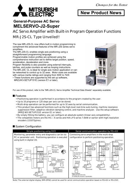
System Configuration<br />
Simple positioning using DI/O<br />
Monitoring, parameter entry and diagnostics can be via<br />
PC or parameter unit. Positioning operation is executed<br />
using built in digital I/O.<br />
Input signals<br />
Program<br />
No. selection<br />
(4bits)<br />
Start signal<br />
etc.<br />
Output signals<br />
Ready<br />
In-position<br />
etc.<br />
RA<br />
RA<br />
MR-<strong>J2</strong>S-CL<br />
CN1<strong>AC</strong>N1B<br />
CN2CN3<br />
RS-232C cable<br />
Relay terminal<br />
block<br />
(MR-TB20)<br />
Manual pulse<br />
generator<br />
(MR-HDP01)<br />
CN1A<br />
Personal<br />
computer<br />
Setup software<br />
(MRZJW3-<br />
SETUP151E)<br />
Serial communication operation by RS-422<br />
Connecting servo amplifiers in the multi-drop<br />
configuration to perform positioning operation.<br />
Master controller<br />
RS-232C/RS-422<br />
converter unit<br />
Personal<br />
computer<br />
(Up to 32 axes)<br />
MR-<strong>J2</strong>S-CL MR-<strong>J2</strong>S-CL MR-<strong>J2</strong>S-CL<br />
Emergency<br />
Emergency<br />
Emergency<br />
stop and<br />
stop and<br />
stop and<br />
CN1A CN1B so on<br />
CN1A CN1B so on<br />
CN1A CN1B so on<br />
CN2 CN3<br />
CN2CN3<br />
CN2CN3<br />
<strong>Servo</strong> motor<br />
RS-422 cable<br />
External digital display<br />
(MR-DP60)<br />
Setup software<br />
(MRZJW3-SETUP151E)<br />
for setting the monitor or parameters<br />
<strong>Servo</strong> motor <strong>Servo</strong> motor <strong>Servo</strong> motor<br />
Note) The external digital display (MR-DP60) cannot be used for serial communication operation based on RS-422 or RS-232C.
Specifications of the <strong>Servo</strong> Amplifier<br />
Item<br />
<strong>Servo</strong> Amp.MR-<strong>J2</strong>S<br />
Voltage/frequency<br />
(Note)<br />
Allowable voltage<br />
Power supply<br />
fluctuation<br />
Allowable frequency<br />
fluctuation<br />
Control system<br />
Dynamic brake<br />
Protective functions<br />
Command system<br />
Operation mode<br />
Program<br />
Operation<br />
specification<br />
Position command<br />
input<br />
Speed command<br />
input<br />
System<br />
Program operation mode<br />
Manual<br />
operation<br />
mode<br />
Manual<br />
home<br />
position<br />
return<br />
mode<br />
Other functions<br />
Structure<br />
JOG<br />
Manual pulse<br />
generator<br />
Dog type<br />
Count type<br />
Data setting type<br />
Stopper type<br />
Home position<br />
ignored<br />
(<strong>Servo</strong>-on position as<br />
home position)<br />
Dog type rear end<br />
reference<br />
Count type front<br />
end reference<br />
Dog cradle type<br />
10CL 20CL 40CL 60CL 70CL 100CL 200CL 350CL 500CL 700CL 10CL1 20CL1 40CL1<br />
Three-phase 200 to 230V/50, 60Hz <strong>AC</strong><br />
or single-phase 230V/50, 60Hz <strong>AC</strong><br />
Three-phase 170 to 253V/50, 60Hz <strong>AC</strong><br />
or single-phase 207 to 253V/50, 60Hz<br />
<strong>AC</strong><br />
Three-phase 200 to 230V/50, 60Hz<br />
<strong>AC</strong><br />
Three-phase 170 to 253V/50, 60Hz<br />
<strong>AC</strong><br />
Within 5%<br />
Single-phase 100 to<br />
120V/50, 60Hz <strong>AC</strong><br />
Single-phase 85 to<br />
127V/50, 60Hz <strong>AC</strong><br />
Sine-wave PWM control/current control system<br />
Built-in<br />
Overcurrent shutoff, regenerative overvoltage shutoff, overload shutoff (electronic thermal<br />
protector), servo motor overheat protection, detector alarm protection, regenerative alarm<br />
protection, undervoltage, instantaneous power failure protection, overspeed protection,<br />
excessive error protection<br />
Program language (programmed by the setup software)<br />
Program capacity: 120 steps<br />
Set by the program language<br />
One-point feed length setting range: 1( m) to 999.999(mm)<br />
A servo motor speed, acceleration and deceleration time constants, and S-pattern acceleration and<br />
deceleration time constants are set by the program language.<br />
The S-pattern acceleration and deceleration time constants can be set by parameter No. 14 as well.<br />
Signed absolute value command system (signed incremental value specification method can be<br />
used), and signed incremental value command system<br />
Depends on the setup of the program language.<br />
Inching is performed by contact input or RS-422 (RS-232C) communication based on the speed<br />
command set by the parameter.<br />
Manual feeding is performed using the manual pulse generator.<br />
Command pulse magnifications 1, 10, and 100 are selected by the parameter.<br />
The Z-phase pulses after passage through the proximity dog are used to make a home position<br />
return. A home position address can be set, a home position shift volume can be set, and a home<br />
position return direction can be selected. A function for retracting automatically on the dog to<br />
return to the home position, and a function for stroke automatic retraction are available.<br />
The detector pulses after a contact with the proximity dog are counted to make a home<br />
position return.<br />
A home position return direction can be selected, a home position shift volume can be set, and<br />
a home position address can be set.<br />
A function for retracting automatically on the dog to return to the home position, and a<br />
function for stroke automatic retraction are available.<br />
A home position return is made without a dog.<br />
Any position can be set as a home position by manual operation and so on, and a home position<br />
address can be set.<br />
The axis is pressed against a stroke end to make a home position return.<br />
A home position return direction can be selected, and a home position address can be set.<br />
The position where the SON signal was turned ON is defined as a home position.<br />
A home position address can be set.<br />
The rear end of the proximity dog is used as a reference point to make a home position return.<br />
A home position return direction can be selected, a home position shift volume can be set, and a<br />
home position address can be set.<br />
A function for retracting automatically on the dog to return to the home position, and a function for<br />
stroke automatic retraction are available.<br />
The front end of the proximity dog is used as a reference point to make a home position return.<br />
A home position return direction can be selected, a home position shift volume can be set, and a<br />
home position address can be set.<br />
A function for retracting automatically on the dog to return to the home position, and a function for<br />
stroke automatic retraction are available.<br />
With the front end of the proximity dog used as a reference point, the first Z-phase pulse is used to<br />
make a home position return.<br />
A home position return direction can be selected, a home position shift volume can be set, and a<br />
home position address can be set.<br />
A function for retracting automatically on the dog to return to the home position, and a function for<br />
stroke automatic retraction are available.<br />
Absolute position detection, backlash correction, overtravel protection by the external limit<br />
switch, software stroke limit, override by external analog control<br />
Forced cooling, open Self-cooling, open<br />
Self-cooling, open (IP00)<br />
(IP00)<br />
(IP00)<br />
Ambient temperature 0 to 55 (non-freezing), storage: 20 to 65 (non-freezing)<br />
Ambient humidity<br />
90%RH or less (non-condensation), storage: 90%RH or less (non-condensation)<br />
Environment Atmosphere<br />
Indoors (without exposure to direct sunlight), without corrosive gas, flammable gas, oil mist,<br />
and dust and dirt<br />
Elevation<br />
Max. 1000m above sea level<br />
Vibration Max. 5.9m/s 2<br />
Mass (kg) 0.7 0.7 1.1 1.1 1.7 1.7 2.0 2.0 4.9 7.2 0.7 0.7 1.1<br />
Note) The rated output capacity and rated speed of the servo motor used with the servo amplifier assume that the power supply voltage<br />
and frequency are as specified in this catalog. They cannot be guaranteed when the power supply voltage is dropped.
Program Operation<br />
Position data, speed of the servo motor, acceleration and deceleration time constants and so on are<br />
created as programs beforehand.<br />
Positioning operation is performed by selecting the created programs and executing them.<br />
Command list<br />
Command Name Setup Setup range Unit<br />
SPN<br />
(Note 1)<br />
STA (Note 2)<br />
STB (Note 2)<br />
STC (Note 2)<br />
STD (Note 2)<br />
MOV<br />
MOVA<br />
MOVI<br />
MOVIA<br />
SYNC<br />
(Note 3)<br />
OUTON<br />
(Note 3, 4)<br />
OUTOF<br />
(Note 3)<br />
Motor speed<br />
SPN<br />
(setting)<br />
Acceleration time<br />
constant<br />
STA<br />
(setting)<br />
Deceleration time STB<br />
constant<br />
(setting)<br />
Acceleration and<br />
STC<br />
deceleration time<br />
(setting)<br />
constants<br />
S-pattern acceleration<br />
STD<br />
and deceleration time<br />
(setting)<br />
constants<br />
Absolute value move MOV<br />
command<br />
(setting)<br />
Absolute value<br />
MOVA<br />
continuous move<br />
(setting)<br />
command<br />
Incremental value MOVI<br />
move command (setting)<br />
Incremental value<br />
continuous move<br />
command<br />
Waiting for external<br />
signal to switch on<br />
External signal ON<br />
output<br />
External signal OFF<br />
output<br />
MOVIA<br />
(setting)<br />
SYNC<br />
(setting)<br />
OUTON<br />
(setting)<br />
OUTOF<br />
(setting)<br />
0 to<br />
instantaneous<br />
permissible<br />
speed<br />
r/min<br />
Indirect<br />
specificati<br />
on (Note 7)<br />
Description<br />
Sets the command speed of the servo motor for<br />
positioning. The setting value must not exceed the<br />
instantaneous permissible speed of the servo motor used.<br />
0 to 20000 ms Sets the acceleration time constant to the rated speed.<br />
0 to 20000 ms Sets the deceleration time constant to the rated speed.<br />
0 to 20000 ms<br />
0 to 100 ms<br />
999999<br />
to 999999<br />
999999<br />
to 999999<br />
999999<br />
to 999999<br />
999999<br />
to 999999<br />
1 to 3<br />
1 to 3<br />
1 to 3<br />
10 STM<br />
m<br />
10 STM<br />
m<br />
10 STM<br />
m<br />
10 STM<br />
m<br />
Sets the acceleration and deceleration time constants to<br />
the rated speed.<br />
Sets the S-pattern acceleration and deceleration time<br />
constants to the rated speed.<br />
Moves the set value as an absolute value.<br />
Moves the set value continuously as an absolute value.<br />
Be sure to use this command together with the [MOV]<br />
command.<br />
Moves the set value as an incremental value.<br />
Moves the set value continuously as an incremental<br />
value.<br />
Be sure to use this command together with the [MOVI]<br />
command.<br />
Stops the next step until the program input 1 (PI1) to<br />
program input 3 (PI3) are turned ON after the<br />
synchronous output (SOUT) command is output.<br />
Turns ON the program output 1 (OUT1) to program<br />
output 3 (OUT3). These signals can be turned OFF after<br />
a setup time has elapsed, by setting an ON time with<br />
parameter No. 74 to 76.<br />
Turns OFF the program output 1 (OUT1) to program<br />
output 3 (OUT3), which were turned ON by the<br />
[OUTON] commands.<br />
Note: 1. The [SPN] command is enabled when the [MOV], [MOVA], [MOVI], or [MOVIA] command is executed.<br />
2. The [STA], [STB], [STC], and [STD] commands are enabled when the [MOV] or [MOVI] command is executed.<br />
3. The [SYNC], [OUTON], [OUTOF], [TRIP], [TRIPI], [COUNT], [LPOS], and [ITP] commands are enabled even while an<br />
instruction is output.<br />
4. If the ON time is set by parameter No. 74 to 76, the next command is executed after the set time has elapsed.<br />
5. If the remaining distance is the setting value or less, the servo motor is not running, or the servo motor is decelerating, the<br />
[ITP] command is skipped and control goes to the next step.<br />
6. The unit of STM is magnification to data.<br />
7. <strong>General</strong>-purpose registers (R1 to R4 and D1 to D4) can be specified to the command setting values.<br />
8. For the content of each command, be sure to confirm "MR-<strong>J2</strong>S-CL <strong>Servo</strong> Amplifier Technical Data Sheets."<br />
<br />
Two types of operation, with which the servo motor speed, acceleration time constant, and deceleration<br />
time constant are the same and the move instruction is different, are executed.<br />
Program<br />
Description<br />
SPN(1000)<br />
STA(200)<br />
STB(300)<br />
MOV(1000)<br />
TIM(10)<br />
MOV(2500)<br />
STOP<br />
<strong>Servo</strong> motor speed 1000(r/min) ........................................ 1)<br />
Acceleration time constant 200(ms) ................................. 2)<br />
Deceleration time constant 300(ms)................................. 3)<br />
Absolute value move instruction 1000 ( 10 STM m) ........ 4)<br />
Dwell 100(ms) ................................................................... 5)<br />
Absolute value move instruction 2500 ( 10 STM m)......... 6)<br />
Program stop<br />
(Note 1)<br />
speed<br />
2)Acceleration time<br />
constant (Note 2)<br />
(200ms)<br />
3)Deceleration<br />
time constant<br />
(Note 2)(300ms)<br />
2)Acceleration time<br />
constant (Note 2)<br />
(200ms)<br />
3)Deceleration<br />
time constant<br />
(Note 2)(300ms)<br />
1)Speed<br />
(1000r/min)<br />
1)Speed<br />
(1000r/min)<br />
Position<br />
0 1000 2500<br />
4)Absolute value move instruction 5)Dwell 6)Absolute value move instruction<br />
(1000 10 STM m)<br />
(100ms) (2500 10 STM m)<br />
Note: 1. The values set as steps (1), (2), and (3) are enabled as long as they are not set again.<br />
2. The setting value is the time elapsing from the stop of the servo motor to the rated speed.
Command Name Setup Setup range Unit<br />
TRIP<br />
(Note 3)<br />
TRIPI<br />
(Note 3)<br />
ITP<br />
(Note 3, 5)<br />
COUNT<br />
(Note 3, 5)<br />
FOR<br />
NEXT<br />
Absolute value<br />
passage point<br />
specification<br />
Incremental<br />
value passage<br />
point<br />
specification<br />
Interrupt<br />
positioning<br />
External pulse<br />
count<br />
Step repeat<br />
command<br />
TRIP<br />
(setting)<br />
TRIPI<br />
(setting)<br />
ITP<br />
(setting)<br />
COUNT<br />
(setting)<br />
FOR<br />
(setting)<br />
NEXT<br />
999999<br />
to 999999<br />
999999<br />
to 999999<br />
0 to<br />
999999<br />
999999<br />
to<br />
999999<br />
0,<br />
1 to 10000<br />
10 STM<br />
m<br />
10 STM<br />
m<br />
10 STM<br />
m<br />
pulse<br />
times<br />
Indirect<br />
specification<br />
Description<br />
(Note 7)<br />
When the motor passes through the current<br />
position, the next step is executed.<br />
While the motor moves by the [MOVI] command or<br />
[MOVIA] command, if the motor has moved for the<br />
moving distance set by the [TRIPI] command since<br />
the [MOVI] command or [MOVIA] command is<br />
issued, the next step is executed. Be sure to write<br />
the [TRIPI] command after the [MOVI] command<br />
or [MOVIA] command.<br />
When the motor has moved for the distance set<br />
beforehand, the motor is stopped by an interrupt<br />
signal. Use this command after the [SYNC]<br />
command in combination.<br />
When the value of the pulse counter exceeds the<br />
count value set in the [COUNT] command, the next<br />
step is executed. Setting [COUNT(0)] clears the<br />
pulse counter to zero.<br />
The steps, enclosed with the [FOR (setting value)]<br />
command and the [NEXT] command, are repeated<br />
for the number of times set beforehand. If zero is<br />
set, the steps are repeated unlimitedly.<br />
LPOS Current<br />
(Note 3) position latch LPOS the input device current latch (LPS).<br />
The latched current position data can be read by a<br />
The current position is latched by the rising edge of<br />
communication command.<br />
TIM Dwell TIM(setting) 1 to 2000 10ms<br />
The next step is waited until the time set<br />
beforehand has elapsed.<br />
ZRT<br />
TIMES<br />
Home position<br />
return<br />
Program count<br />
instruction<br />
ZRT<br />
TIMES<br />
(setting)<br />
STOP Program stop STOP<br />
0,<br />
1 to 10000<br />
times<br />
A manual home position return is executed.<br />
Put the [TIMES (setting value )] command on the<br />
top of the program to set the number of times of<br />
program execution. If zero is set, the program is<br />
repeated unlimitedly.<br />
The program being executed is stopped.<br />
Be sure to write this command in the final line.<br />
<br />
The steps enclosed with the [FOR (setting value)] command and the [NEXT] command are repeated for the<br />
number of times set beforehand to execute the operation.<br />
Program<br />
Description<br />
SPN(1000)<br />
STC(20)<br />
MOV(1000)<br />
TIM(10)<br />
FOR(3)<br />
MOVI(100)<br />
TIM(10)<br />
NEXT<br />
STOP<br />
<strong>Servo</strong> motor speed 1000(r/min)<br />
Acceleration and deceleration time constants 20(ms)<br />
Absolute value move instruction 1000 ( 10 STM m)<br />
Dwell 100(ms)<br />
Step repeat command start 3(times).....................................1)<br />
Increment value move instruction 100( 10 STM m)..............2)<br />
Dwell 100(ms) ........................................................................3)<br />
Step repeat command end<br />
Program stop<br />
Speed<br />
Position<br />
0 1000 1100 1200 1300<br />
Steps (2) and (3) are repeated for the number<br />
of times specified by step (1).
OPEN<br />
OPEN<br />
OPEN<br />
OPEN<br />
OPEN<br />
OPEN<br />
OPEN<br />
OPEN<br />
OPEN<br />
OPEN<br />
<strong>Servo</strong> Amplifier Outline Drawings<br />
(Dimension unit: mm)<br />
MR-<strong>J2</strong>S-10CL, 20CL, 10CL1, 20CL1<br />
MR-<strong>J2</strong>S-40CL, 60CL, 40CL1<br />
6 mounting<br />
hole<br />
50 (70) 135<br />
6<br />
Display<br />
setting<br />
section<br />
cover<br />
(20)<br />
Clearance necessary<br />
for heat dissipation (40 or more)<br />
Terminal layout<br />
(terminal cover open)<br />
6 mounting<br />
hole<br />
70<br />
22<br />
(70)<br />
Display<br />
setting<br />
section<br />
cover<br />
(20)<br />
135<br />
Clearance necessary<br />
for heat dissipation (40 or more)<br />
Terminal layout<br />
(terminal cover open)<br />
(7)<br />
168<br />
6 156<br />
C<br />
N<br />
1<br />
A<br />
C<br />
N<br />
2<br />
E<br />
N<br />
C<br />
( )<br />
C<br />
N<br />
1<br />
B<br />
C<br />
N<br />
3<br />
L1 L2 L3 Terminal<br />
cover<br />
U V W<br />
Clearance<br />
necessary<br />
6<br />
for heat<br />
PE terminal dissipation<br />
Symbols<br />
(40 or more)<br />
D C P L21 L11<br />
C<br />
N<br />
1<br />
A<br />
C<br />
N<br />
2<br />
E<br />
N<br />
C<br />
( )<br />
For grounding<br />
3 places (M4)<br />
M4 screw<br />
Terminal block symbols<br />
L1 L2<br />
4<br />
U V W<br />
For single-phase 100V<strong>AC</strong><br />
Terminal block symbols<br />
L1 L2 L3<br />
U V W<br />
For three-phase 200V<strong>AC</strong><br />
or single-phase 230V<strong>AC</strong><br />
C<br />
N<br />
1<br />
B<br />
C<br />
N<br />
3<br />
(7)<br />
168<br />
6 156<br />
C<br />
N<br />
1<br />
A<br />
C<br />
N<br />
2<br />
E<br />
N<br />
C<br />
( )<br />
L1 L2 L3<br />
U V W<br />
6<br />
PE terminal<br />
C<br />
N<br />
1<br />
B<br />
C<br />
N<br />
3<br />
Symbols<br />
D C PL21 L11<br />
Terminal<br />
cover<br />
Clearance<br />
necessary<br />
for heat<br />
dissipation<br />
(40 or more)<br />
C<br />
N<br />
1<br />
A<br />
C<br />
N<br />
2<br />
E<br />
N<br />
C<br />
( )<br />
For grounding<br />
3 places (M4)<br />
Terminal block symbols<br />
L1 L2<br />
U V W<br />
For single-phase 100V<strong>AC</strong><br />
4<br />
Terminal block symbols<br />
L1 L2 L3<br />
U V W<br />
M4 screw<br />
For three-phase 200V<strong>AC</strong><br />
or single-phase 230V<strong>AC</strong><br />
C<br />
N<br />
1<br />
B<br />
C<br />
N<br />
3<br />
MR-<strong>J2</strong>S-70CL, 100CL<br />
MR-<strong>J2</strong>S-200CL, 350CL<br />
(7)<br />
168<br />
6 156<br />
6 mounting<br />
hole<br />
70 (70) 190<br />
22<br />
Display<br />
setting<br />
section<br />
cover<br />
22<br />
C<br />
N<br />
1<br />
A<br />
C<br />
N<br />
2<br />
E<br />
N<br />
C<br />
( )<br />
L1 L2 L3<br />
U V W<br />
42<br />
C<br />
N<br />
1<br />
B<br />
C<br />
N<br />
3<br />
6<br />
Terminal<br />
cover<br />
Clearance<br />
necessary<br />
for heat<br />
dissipation<br />
(40 or more)<br />
Symbols<br />
D C PL21 L11<br />
(20)<br />
Clearance necessary<br />
for heat dissipation (40 or more)<br />
Terminal layout<br />
(terminal cover open)<br />
C<br />
N<br />
1<br />
A<br />
C<br />
N<br />
2<br />
E<br />
N<br />
C<br />
( )<br />
M4 screw<br />
For grounding<br />
3 places (M4)<br />
Terminal block symbols<br />
C<br />
N<br />
1<br />
B<br />
C<br />
N<br />
3<br />
6 mounting<br />
hole<br />
168<br />
156 6<br />
90 (70) 195<br />
78<br />
Display<br />
setting<br />
section<br />
cover<br />
C<br />
N<br />
1<br />
A<br />
C<br />
N<br />
2<br />
E<br />
N<br />
C<br />
( )<br />
C<br />
N<br />
1<br />
B<br />
C<br />
N<br />
3<br />
Clearance<br />
necessary<br />
for heat<br />
dissipation<br />
(40 or more)<br />
(20)<br />
Clearance necessary<br />
for heat dissipation (40 or more)<br />
6<br />
Terminal layout<br />
(terminal cover open)<br />
FAN wind<br />
direction<br />
FAN<br />
M4 screw<br />
For grounding<br />
3 places (M4)<br />
Terminal block symbols<br />
C<br />
N<br />
1<br />
A<br />
C<br />
N<br />
2<br />
E<br />
N<br />
C<br />
( )<br />
C<br />
N<br />
1<br />
B<br />
C<br />
N<br />
3<br />
6<br />
L1 L2 L3<br />
U V W<br />
L11 L21 D P C N<br />
L1 L2 L3 U V W<br />
MR-<strong>J2</strong>S-500CL<br />
MR-<strong>J2</strong>S-700CL<br />
7.5<br />
2- 6 mounting<br />
hole<br />
130<br />
(70)<br />
6 118 6<br />
(20)<br />
200<br />
5<br />
Terminal layout<br />
(terminal cover open)<br />
7.5<br />
2- 6 mounting<br />
hole<br />
180 (70)<br />
200<br />
10 160 10<br />
138 62<br />
6<br />
(20)<br />
Terminal layout<br />
(terminal cover open)<br />
OPEN<br />
OPEN<br />
250<br />
7.5 235<br />
C<br />
N<br />
1<br />
A<br />
C<br />
N<br />
2<br />
E<br />
N<br />
C<br />
( )<br />
C<br />
N<br />
1<br />
B<br />
C<br />
N<br />
3<br />
FAN FAN<br />
6<br />
FAN wind direction<br />
TE1 TE2<br />
Terminal block symbols<br />
PE<br />
L1<br />
L2<br />
L3<br />
C<br />
P<br />
N<br />
U<br />
V<br />
W<br />
TE1<br />
L11<br />
L21<br />
TE2<br />
Terminal screw sizes<br />
C<br />
N<br />
1<br />
A<br />
C<br />
N<br />
2<br />
E<br />
N<br />
C<br />
( )<br />
TE1 M4<br />
TE2 M3.5<br />
PE M4<br />
C<br />
N<br />
1<br />
B<br />
C<br />
N<br />
3<br />
350<br />
7.5 335<br />
C<br />
N<br />
1<br />
A<br />
C<br />
N<br />
2<br />
E<br />
N<br />
C<br />
( )<br />
C<br />
N<br />
1<br />
B<br />
C<br />
N<br />
3<br />
FAN<br />
6<br />
FAN wind<br />
TE1 TE2<br />
direction<br />
Terminal block symbols L11 Terminal screw sizes<br />
TE2<br />
L21<br />
TE1 M4<br />
TE2 M3.5<br />
L1 L2 L3 C P N U V W TE1 PE M4<br />
PE<br />
C<br />
N<br />
1<br />
A<br />
C<br />
N<br />
2<br />
E<br />
N<br />
C<br />
( )<br />
C<br />
N<br />
1<br />
B<br />
C<br />
N<br />
3
MR Configurator <br />
MRZJW3-SETUP151E<br />
This software allows you to perform a setup, provide a monitor display, run diagnostics, write and read parameter<br />
values, and perform test operation easily using a personal computer.<br />
Features<br />
(1) Compatibility with Windows 95, Windows 98, Windows Me, Windows NT<br />
Workstation 4.0, and Windows 2000 Professional (Note 1) (English version).<br />
(2) A wide variety of monitor functions<br />
The graph display function can show servo motor conditions, such as the<br />
instruction pulses, droop pulses, and speeds, with a trigger of an input signal.<br />
Test operation on personal computer<br />
(3) Test operation on personal computer<br />
The servo motor can be test-run easily on a personal computer.<br />
Operating conditions<br />
(Note 1, 2)<br />
Personal<br />
computer<br />
OS<br />
Display<br />
Keyboard<br />
Mouse<br />
Printer<br />
Communic<br />
ation cable<br />
IBM PC/AT compatible where the English version of<br />
Windows 95, Windows 98, Windows Me, Windows<br />
NT Workstation 4.0, or Windows 2000 Professional<br />
operates.<br />
Processor: Pentium 133MHz or more (Windows 95,<br />
Windows 98, Windows NT 4.0, Windows<br />
2000), Pentium 150MHz or more<br />
(Windows Me)<br />
Memory: 16MB or more (Windows 95), 24MB or more<br />
(Windows 98), 32MB or more (Windows<br />
Me, Windows NT 4.0, Windows 2000)<br />
Free hard disk space : 30MB or more<br />
Serial port used.<br />
Windows 95, Windows 98, Windows Me, Windows<br />
NT Workstation 4.0, Windows 2000 Professional<br />
(English version)<br />
800 600 or more display that can show 256 or<br />
more colors<br />
Keyboard that can be connected to the above<br />
personal computer<br />
Mouse that can be connected to the above personal<br />
computer. However, a serial mouse is not used.<br />
Printer that can be connected to the above personal<br />
computer.<br />
MR-CPCATCBL3M<br />
Specifications<br />
The MR-<strong>J2</strong>S-CL type allows you to use the following functions.<br />
Item<br />
Description<br />
Batch display, fast display, and graph<br />
Monitor<br />
display<br />
Alarm display, alarm history, and alarm<br />
Alarm<br />
occurrence-time data display<br />
DI/DO display, function device display,<br />
unrotated reason display, cumulative<br />
power-on display, software number display,<br />
Diagnoses<br />
motor information display, tuning data<br />
display, ABS data display, and axis name<br />
setting<br />
Parameter setting, change list display,<br />
Parameters detail information display, tuning, and<br />
device setting<br />
JOG operation, positioning operation,<br />
Test operation motor-less operation, DO forced output, and<br />
program test operation<br />
Advanced Machine analyzer, gain search, and<br />
functions machine simulation<br />
Program data Program data and indirect addressing<br />
File operation Data read/save, print<br />
Others<br />
Help display<br />
Note 1. Windows and Windows NT are the registered trademarks of Microsoft Corporation in the U.S.A. and other countries.<br />
2. This software may not operate properly on some personal computers.<br />
3. MR-<strong>J2</strong>S- CL(1) operates with MRZJW3-SETUP151E software version E1 or later.<br />
! Safety Instructions<br />
To use the products given in this product news to the optimum, always read<br />
the "Specifications" and "Technical Data Sheets" carefully before use.<br />
MEE(0301)