A Low-Power CMOS Analog Multiplier - IEEE Xplore
A Low-Power CMOS Analog Multiplier - IEEE Xplore
A Low-Power CMOS Analog Multiplier - IEEE Xplore

Create successful ePaper yourself
Turn your PDF publications into a flip-book with our unique Google optimized e-Paper software.
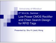
100 <strong>IEEE</strong> TRANSACTIONS ON CIRCUITS AND SYSTEMS—II: EXPRESS BRIEFS, VOL. 53, NO. 2, FEBRUARY 2006<br />
A <strong>Low</strong>-<strong>Power</strong> <strong>CMOS</strong> <strong>Analog</strong> <strong>Multiplier</strong><br />
Chunhong Chen, Senior Member, <strong>IEEE</strong>, and Zheng Li<br />
Abstract—A multiplier is an important component for many<br />
analog applications. This paper presents a low power <strong>CMOS</strong><br />
analog multiplier with performance analysis and design considerations.<br />
Experiments with SPICE simulation and results from<br />
chip testing show that this new structure has extremely low power<br />
consumption with comparable linearity and noise performance,<br />
making it very attractive for use in a variety of analog circuits.<br />
Index Terms—<strong>Analog</strong> integrated circuits, analog multipliers,<br />
<strong>CMOS</strong>, low-power design.<br />
I. INTRODUCTION<br />
AN ANALOG multiplier is an important subcircuit for<br />
many applications such as adaptive filters and frequency<br />
modulators [1]–[10]. It is intended to perform a linear product<br />
of two continuous signals and , yielding an output ,<br />
where is a constant with suitable dimension. Driven by the<br />
early work of Gilbert [11], a variety of multipliers have been<br />
designed for different optimization objectives [3]–[10]. A<br />
general idea behind these designs is to use electronic devices to<br />
process the input signals, followed by a cancellation/minimization<br />
of errors caused by nonlinearity of the devices. Due to the<br />
popularity of advanced <strong>CMOS</strong> technology, MOS transistors<br />
are a natural choice for the devices, while differential circuit<br />
structure is widely used for nonlinarity cancellation [3], [13].<br />
The readers are referred to [7] for recent survey on MOS<br />
multipliers.<br />
In this paper, we present a new multiplier with <strong>CMOS</strong> structure<br />
with emphasis on low power consumption. We analyze various<br />
performance metrics of the multiplier and provide some<br />
design considerations. It is demonstrated in particular that this<br />
multiplier is much better than other structures in terms of power<br />
consumption, and is hence especially suitable for implementation<br />
of large-scale circuits.<br />
II. MULTIPLIER STRUCTURE<br />
For <strong>CMOS</strong> analog multiplier design, most transistors are biased<br />
to operate in the saturation region where the drain current<br />
of the device is given by [14]<br />
where<br />
is the transconductance parameter,<br />
the threshold voltage of the device, and the channel-<br />
Manuscript received March 18, 2005; revised June 1, 2005. This work was<br />
supported in part by the National Sciences and Engineering Research Council<br />
of Canada (NSERC) under Grant 249499-02. This paper was recommended by<br />
Associate Editor T. Saito.<br />
The authors are with the Department of Electrical and Computer Engineering,<br />
University of Windsor, ON N9B 3P4, Canada (e-mail: cchen@uwindsor.ca;<br />
e-mail: li1234b@uwindsor.ca).<br />
Digital Object Identifier 10.1109/TCSII.2005.857089<br />
(1)<br />
length modulation effect for long channel devices. It can be seen<br />
that in the saturation region, low power consumption requires a<br />
small value of which leads to a reduced input range. By<br />
biasing the transistors to operate in the linear region instead,<br />
one can reduce the drain current while keeping a relatively large<br />
input range. The drain current in linear region is given by [14]<br />
Since<br />
in linear region, the overdrive voltage<br />
can be biased to increase the input range. The drain current can<br />
remain a proper value by decreasing , keeping the power<br />
dissipation at same level. Considering the fact that pMOS<br />
transistors need less drain current with larger overdrive voltage<br />
compared with nMOS transistors, pMOS transistors<br />
are preferably chosen in the input terminals for operations<br />
in either saturation or linear region.<br />
Our basic idea in designing low-power multipliers is to<br />
fit most transistors into linear region and use pMOS devices<br />
to operate in saturation region. Fig. 1 shows the proposed<br />
<strong>CMOS</strong> multiplier structure which consists of 4 pMOS transistors<br />
( – ) operating in saturation region and 8 nMOS<br />
transistors ( – and – ) operating in linear region.<br />
Throughout the paper, the upper case letters, and , represent<br />
common-mode (dc bias) components, while the lower case<br />
letters, and , represent small (input) signals. Assuming that<br />
all transistors in Fig. 1 are biased to operate in proper (linear<br />
or saturation) region, we can prove that this topology achieves<br />
multiplication, i.e.,<br />
A potential advantage of this structure is that a larger input<br />
range can be obtained with only pMOS transistors in their saturation<br />
region. In other words, for the same input range, a lower<br />
supply voltage can be used. The transistors – in saturation<br />
region reduce , pushing up the input range for signal<br />
.<br />
For a given DC bias, the output range of the multiplier also<br />
depends on<br />
which has a maximum value in<br />
order to keep – and – in linear region. While exhibiting<br />
the ability of canceling nonlinearity, the circuit still has<br />
a linearity error due to temperature, body effect of transistors<br />
– , and possible device mismatches.<br />
The required bias conditions for Fig. 1 can be written as<br />
for –<br />
(4)<br />
for – (5)<br />
The bias voltage of – is chosen to be in order to<br />
keep as low as possible, allowing – for a larger input<br />
(2)<br />
(3)<br />
1057-7130/$20.00 © 2006 <strong>IEEE</strong>
CHEN AND LI: LOW-POWER <strong>CMOS</strong> ANALOG MULTIPLIER 101<br />
Fig. 1.<br />
Proposed multiplier topology.<br />
range. Typical values to be used are: V, V,<br />
V, V, and V. For instance,<br />
when all transistors have same size of m/0.35 m<br />
with , both and turn out to be 16.1 mV.<br />
III. QUANTITATIVE ANALYSIS AND VERIFICATION<br />
The performance metrics for multipliers include linearity,<br />
input range, chip area cost, power consumption, frequency<br />
range, and noise. Depending upon applications, some of them<br />
can be more important than others. Also, it is not uncommon<br />
that some metrics need to be traded for others. For instance,<br />
as the power consumption of a multiplier is to be optimized,<br />
its linearity performance tends to get worse. This requires a<br />
reasonable tradeoff between the two. In this section, we give a<br />
quantitative analysis on power consumption and noise for the<br />
proposed multiplier, which is verified by the Spectre Simulator<br />
from the Cadence tool.<br />
A. <strong>Power</strong> Consumption<br />
Given a constant supply voltage, the power consumption of<br />
Fig. 1 can be estimated by looking at the total output current<br />
which is given by<br />
, i.e.,<br />
Fig. 2. Total current with respect to (a) X and (b) K (with W=L =<br />
0:8 m/0.35 m).<br />
The simulation results for the total current in Fig. 1<br />
with respect to and (with uniform transistor size of<br />
m m) are shown in Fig. 2(a) and (b) with both<br />
and being 0.2 V.<br />
B. Noise<br />
Noise is another consideration in designing multipliers. The<br />
total output noise of Fig. 1 is given by<br />
Since<br />
are very small compared with the input signals<br />
(if the circuit is properly biased), we have the following<br />
approximate result:<br />
This indicates that the power consumption has nothing to do<br />
with signal and dc bias for transistors N1–N4.<br />
(6)<br />
(7)<br />
where<br />
(8)<br />
(9)<br />
(10)<br />
(11)
102 <strong>IEEE</strong> TRANSACTIONS ON CIRCUITS AND SYSTEMS—II: EXPRESS BRIEFS, VOL. 53, NO. 2, FEBRUARY 2006<br />
Fig. 4. Recommended multiplier structure by [7].<br />
Fig. 5. Total current comparison for Figs. 1 and 4.<br />
Fig. 3. Noise simulation results for Fig. 1. (a) Input-referred noise voltage<br />
of Fig. 1 versus K ;K , and K . (b) Input-referred noise voltage of Fig. 1<br />
versus (Y 0 X).<br />
The total input noise is<br />
(12)<br />
This suggests that , and should be well designed<br />
to improve the noise performance. Also, the input-referred noise<br />
depends on and that vary with the value of .Ifwe<br />
increase or while keeping other parameters the same,<br />
the input-noise will decrease. This is verified by experimental<br />
results in Fig. 3(a). The input noise increases with the value of<br />
, as shown in Fig. 3(b).<br />
IV. EXPERIMENT AND COMPARISON<br />
In order to estimate the performance of the proposed<br />
structure, we conducted the experiments on linearity, power<br />
consumption and noise. To ensure a fair comparison, we also<br />
simulated the most recommended structure of eight multipliers<br />
provided in [7]. For convenience, this structure is redrawn in<br />
Fig. 4. For both circuits in Figs. 1 and 4, a standard 0.35- m<br />
<strong>CMOS</strong> technology was used with the supply voltage of 1.5 V.<br />
Unless otherwise specified, all transistors use the identical size<br />
of m/0.35 m and the circuits are biased to have<br />
typical values (in Fig. 4, V, and V were<br />
used) with the input range of V for both and (i.e.,<br />
V).<br />
Fig. 6. Input-referred noise simulation results for Figs. 1 and 4.<br />
A. Output Current<br />
To compare the power consumption of Figs. 1 and 4, we used<br />
same power supply and input signals. Fig. 5 shows the total currents<br />
for these two structures with both and being a 100-kHz<br />
0.2-V sinusoidal-wave. The circuit of Fig. 1 exhibits lower<br />
power consumption which is nearly one third of that in Fig. 4.<br />
B. Noise<br />
Noise comparison is given in Fig. 6. Our experiment shows<br />
that the structure in Fig. 1 has a little higher input-referred noise<br />
compared with the structure of Fig. 4 when applied with similar<br />
input signal level.<br />
C. Linearity<br />
We look at the DC transfer characteristics of<br />
versus and for Fig. 1 with V and V. The<br />
results are plotted in Fig. 7(a) and (b) where the linearity gets<br />
worse as and increase. In particular, when V,
CHEN AND LI: LOW-POWER <strong>CMOS</strong> ANALOG MULTIPLIER 103<br />
(a)<br />
(b)<br />
Fig. 8. THD for Figs. 1 and 4. (a) THD of signal x with 2y =0:4 V. (b) THD<br />
of signal y with 2x =0:4 V.<br />
Fig. 7. The dc transfer characteristics of Fig. 1. (a) V 0 V versus x.<br />
(b) V 0 V versus y.<br />
the linearity error is measured to be 2.7%. From our simulation,<br />
the linearity error of Fig. 4 reaches 5.3% for same and ,<br />
which is almost twice as much as in Fig. 1. Fig. 8(a) and (b)<br />
show the total harmonic distortion (THD) when a constant dc<br />
voltage (0.2 V) is applied to (or ) while a 100-kHz 0.2<br />
sinusoidal-wave is applied to (or ). It can be seen that the<br />
THD (when V) of signal for Fig. 1 is much<br />
less than that for Fig. 4. With signal , two structures have the<br />
comparable THD.<br />
Body effect may be another source of linearity errors. We<br />
show that the structure of Fig. 1 has less body effect than that<br />
of Fig. 4. Indeed, for the transistors – in Fig. 1, is<br />
normally very low and the value of their is very small. The<br />
transistors – and – have no body effect as their<br />
source terminals are connected to and the ground, respectively.<br />
Fig. 9 shows the linearity comparison with and without<br />
body effect for signal and – V when Vor<br />
– V when V). The curves in Fig. 9(b) overlap,<br />
implying that the body effect has no impact on the linearity error<br />
due to signal .<br />
In summary, experimental results have shown that the proposed<br />
multiplier structure consumes much less power compared<br />
with the existing structures. The total supply current can be further<br />
reduced by some design considerations such as using a<br />
smaller value of and bigger size for transistors - .<br />
The proposed multiplier was sent to the Canadian Microelectronics<br />
Corporation (CMC) for fabrication with 0.35- m <strong>CMOS</strong><br />
technology. Fig. 10 shows its layout diagram. We performed the<br />
post-layout simulation for Fig. 10 and also tested the fabricated<br />
chip. The comparison is shown in Table I, where the post-layout<br />
Fig. 9.<br />
Linearity errors with and without body effects. (a) Linearity error<br />
versus x (when y =0:2 V). (b) Linearity error versus y (when x =0:2 V).<br />
simulation results are very close to pre-layout simulation shown<br />
before (see Sections IV-A and IV-C). In this table, the linearity<br />
error of (or ) is measured when a 100-kHz 0.2-V sinusoidal-wave<br />
is applied, while the total current and power consumption<br />
are measured with V, V,<br />
V, and V. We see that the overall performance<br />
of the real chip is much worse than simulation results.<br />
We believe this is mainly due to the added pads for chip fabrication<br />
since the core area of proposed multiplier (i.e., Fig. 10)<br />
is just a very small portion (less than 5%) of the whole chip.
104 <strong>IEEE</strong> TRANSACTIONS ON CIRCUITS AND SYSTEMS—II: EXPRESS BRIEFS, VOL. 53, NO. 2, FEBRUARY 2006<br />
significant power reduction has been achieved by both well-designed<br />
structure and fine-tuned parameters. The results from<br />
simulation and chip testing have shown the desirable performance<br />
of the multiplier, which makes it very suitable for use<br />
in low power implementation of large-scale analog circuits.<br />
Fig. 10. Physical layout of Fig. 1.<br />
TABLE I<br />
COMPARISON OF POST-LAYOUT SIMULATION AND TESTING RESULT<br />
Layout of these pads was changed by the CMC to meet some<br />
requirements (such as final design rule check—DRC) for fabrication,<br />
and thus not available for full post-layout simulation.<br />
Other factors such as process variations and parasitic parameters<br />
may also contribute to the significant difference between<br />
simulation results and measurements shown in Table I.<br />
V. CONCLUSION<br />
A low-power <strong>CMOS</strong> analog multiplier has been proposed.<br />
Several important performance metrics have been analyzed. A<br />
REFERENCES<br />
[1] K. Bult and H. Wallinga, “A four-quadrant analog multiplier,” <strong>IEEE</strong> J.<br />
Solid-State Circuits, vol. SC-21, no. 3, pp. 430–435, Jun. 1986.<br />
[2] O. Changyue, C. Peng, and X. Yizhong, “Study of switched capacitor<br />
multiplier,” in Proc. Int. Conf. Circuits Syst, Jun. 1991, pp. 234–237.<br />
[3] Z. Wang, “A four-transistor four-quadrant analog multiplier using MOS<br />
transistors operating in the saturation region,” <strong>IEEE</strong> Trans. Instrum.<br />
Meas., vol. 42, no. 1, pp. 75–77, Feb. 1993.<br />
[4] H. R. Mehrvarz and C. Y. Kwok, “A large-input-dynamic-range multiinput<br />
floating gate MOS four-quadrant analog multiplier,” in Proc. <strong>IEEE</strong><br />
Int. Solid-State Circuits Conf., Feb. 1995, pp. 60–61.<br />
[5] S. Liu and C. Chang, “<strong>CMOS</strong> subthreshold four quadrant multiplier<br />
based on unbalanced source coupled pairs,” Int. J. Electron., vol. 78,<br />
pp. 327–332, Feb. 1995.<br />
[6] B. Maundy and P. Aronhime, “Useful multipliers for low-voltage applications,”<br />
in Proc. <strong>IEEE</strong> Int. Symp. Circuits Syst., vol. 1, May 2002, pp.<br />
26–29.<br />
[7] G. Han and E. Sanchez-Sinencio, “<strong>CMOS</strong> transconductance multipliers:<br />
A tutorial,” <strong>IEEE</strong> Trans. Circuits Syst. II, <strong>Analog</strong> Digit. Signal Process.,<br />
vol. 45, no. 12, pp. 1550–1563, Dec. 1998.<br />
[8] U. Gatti, F. Maloberti, and G. Torelli, “<strong>CMOS</strong> triode-transistor transconductor<br />
for high-frequency continuous-time filters,” Proc. IEE Circuits,<br />
Devices, Syst., vol. 141, no. 6, pp. 462–468, Dec. 1994.<br />
[9] S. Liu and Y. Hwang, “CMOC four-quadrant multiplier using bias feedback<br />
techniques,” <strong>IEEE</strong> J. Solid-State Circuits, vol. 29, pp. 750–752,<br />
Jun. 1994.<br />
[10] S. I. Liu, “<strong>Low</strong> voltage <strong>CMOS</strong> four-quadrant multiplier,” Electron. Lett.,<br />
vol. 30, pp. 2125–2126, Dec. 1994.<br />
[11] B. Gibert, “A precision four-quadrant multiplier with subnanosecond<br />
response,” <strong>IEEE</strong> J. Solid-State Circuits, vol. SC-3, no. 6, pp. 353–365,<br />
Dec. 1968.<br />
[12] D. C. Soo and R. G. Meyer, “A four-quadrant nMOS analog multiplier,”<br />
<strong>IEEE</strong> J. Solid-State Circuits, vol. SC-17, no. 6, pp. 1174–1178, Dec.<br />
1982.<br />
[13] J. N. Babanezhad and G. C. Temes, “A 20-V four-quadrant <strong>CMOS</strong><br />
analog multiplier,” <strong>IEEE</strong> J. Solid-State Circuits, vol. SC-20, no. 6, pp.<br />
1158–1168, Dec. 1985.<br />
[14] B. Razavi, Design of <strong>Analog</strong> <strong>CMOS</strong> Integrated Circuits. New York:<br />
McGraw-Hill, 2001.