Tsunami QuickBridge II T1/E1 Version 2.2 Quick Install Guide
Tsunami QuickBridge II T1/E1 Version 2.2 Quick Install Guide
Tsunami QuickBridge II T1/E1 Version 2.2 Quick Install Guide

You also want an ePaper? Increase the reach of your titles
YUMPU automatically turns print PDFs into web optimized ePapers that Google loves.
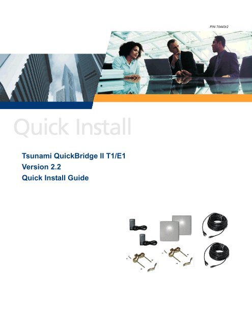
P/N 70443r2<br />
<strong>Tsunami</strong> <strong><strong>Quick</strong>Bridge</strong> <strong>II</strong> <strong>T1</strong>/<strong>E1</strong><br />
<strong>Version</strong> <strong>2.2</strong><br />
<strong>Quick</strong> <strong>Install</strong> <strong>Guide</strong>
<strong>Tsunami</strong> <strong><strong>Quick</strong>Bridge</strong> <strong>II</strong> <strong>T1</strong>/<strong>E1</strong> <strong>Quick</strong> <strong>Install</strong> <strong>Guide</strong><br />
Introduction<br />
The <strong><strong>Quick</strong>Bridge</strong> is a complete kit for enabling a wireless broad bandwidth link between two locations. The<br />
equipment is pre-configured at the factory to be mounted and connected to your LAN network. Both ends of the<br />
link are provided in this kit along with cables and mounting hardware.<br />
The product’s principle components consist of a radio unit and a power & Ethernet adapter. The radio is an allin-one,<br />
outdoor unit with an integrated antenna, designed to be mounted on a pole or on a tower structure.<br />
Power and Ethernet connections to the radio unit are supplied through a UV-protected, CAT 5 cable attached to<br />
the power & Ethernet adapter. The power & Ethernet adapter should be located inside a building. A straight<br />
cable is required when connecting to a PC and a crossover cable when connecting to a hub or switch.<br />
The <strong>Tsunami</strong> <strong><strong>Quick</strong>Bridge</strong> <strong>II</strong> must be installed professionally.<br />
Perform the following steps in this chapter to install the <strong><strong>Quick</strong>Bridge</strong> <strong>II</strong> system:<br />
1. Gather Required Tools<br />
2. Unpack the Shipping Box Contents<br />
3. Pre-assemble Hardware<br />
4. Connect the Cables<br />
5. Test Back-to-Back<br />
6. <strong>Install</strong> the Software<br />
7. Setup for Configuration<br />
8. Mount the Radio Outdoors<br />
9. Align the Antenna<br />
STEP 1. GATHER REQUIRED TOOLS AND MATERIALS<br />
You should have the following tools available before installing the <strong>Tsunami</strong> <strong><strong>Quick</strong>Bridge</strong> <strong>II</strong> radios:<br />
• Phillips (cross-tip) screwdrivers<br />
• Small blade standard screwdriver<br />
• Large blade standard screwdriver<br />
• Wire crimpers (if using connectors that are not pre-made)<br />
• Adjustable 6” wrench<br />
• Weatherproofing material for sealing external connectors (such as butyl tape)<br />
• Straight-through UV-protected CAT 5 or CAT 5e Ethernet cable for connecting to PC, or crossover cable if<br />
connecting to a hub or a switch.<br />
Note: Maximum cable lengths to be used with the <strong>Tsunami</strong> <strong><strong>Quick</strong>Bridge</strong> are as follows:<br />
GPS: 25 feet (approx. 8 m)<br />
<strong>T1</strong>/<strong>E1</strong>: 655 feet (approx. 200 m)<br />
Power/Ethernet: 246 feet (approx. 75 m)<br />
Maximum cable length from the power source to the <strong><strong>Quick</strong>Bridge</strong> unit is 75 m, but the cable from the<br />
power source to the next device is a total of 100 m. So if you connect a 75 m cable to the <strong><strong>Quick</strong>Bridge</strong><br />
unit, you can use a 25 m cable to connect the power supply to your PC or switch.<br />
Copyright © 2005 Proxim Corporation. All rights reserved. 2
<strong>Tsunami</strong> <strong><strong>Quick</strong>Bridge</strong> <strong>II</strong> <strong>T1</strong>/<strong>E1</strong> <strong>Quick</strong> <strong>Install</strong> <strong>Guide</strong><br />
STEP 2. UNPACK THE SHIPPING BOX CONTENTS<br />
The product’s shipping boxes should be left intact and sheltered until arrival at the installation site. Carefully<br />
unpack the <strong>Tsunami</strong> <strong><strong>Quick</strong>Bridge</strong> <strong>II</strong> shipment and check for any shipping damage or missing parts. There are<br />
two sets of equipment in the box, as displayed in the following figure.<br />
The <strong>Tsunami</strong> <strong><strong>Quick</strong>Bridge</strong> <strong>II</strong> <strong>T1</strong>/<strong>E1</strong> <strong>Quick</strong> <strong>Install</strong> <strong>Guide</strong> and a Documentation and Software CD also are included<br />
in the shipment. (Extra screw-on caps to seal unused connector ports are also provided.)<br />
Contact Technical Support regarding any missing or damaged parts.<br />
Notes:<br />
(1) If the shipping container shows signs of damage, immediately notify the transportation company. Upon<br />
receipt, inspect contents to ensure no parts are missing or damaged.<br />
(2) Save the original shipping boxes to re-use for shipping the equipment back to the factory, for storage, or for<br />
re-shipping the equipment to another location.<br />
Copyright © 2005 Proxim Corporation. All rights reserved. 3
<strong>Tsunami</strong> <strong><strong>Quick</strong>Bridge</strong> <strong>II</strong> <strong>T1</strong>/<strong>E1</strong> <strong>Quick</strong> <strong>Install</strong> <strong>Guide</strong><br />
STEP 3. PRE-ASSEMBLE HARDWARE<br />
Proxim recommends that you pre-assemble the radio mounting hardware on the ground to familiarize yourself<br />
with the equipment and check for any possible damaged or missing components before mounting the radios.<br />
This includes attaching the mounting bracket and loosely attaching the washers, lock washers, and lock nuts to<br />
the radios. <strong>Install</strong>ers having prior installation experience may choose to skip this step and proceed with Step 3.<br />
• For outdoor installation, the <strong>Tsunami</strong> <strong><strong>Quick</strong>Bridge</strong> <strong>II</strong> package includes a CAT 5e cable. This is a higher<br />
grade than a standard cable.<br />
• For indoor installation, use either a standard CAT 5e or a CAT 5 cable when connecting to the PC.<br />
Pre-Assemble Mounting Hardware<br />
Perform these steps on each radio to pre-assemble the mounting hardware on the radios:<br />
1. Place mounting bracket onto mounting hole on rear of radio unit; insert mounting screw<br />
2. Screw locking bolt onto mounting screw.<br />
3. Raise mounting bracket to proper angle and tighten carriage bolt. Use a nut driver or socket wrench to<br />
firmly tighten the carriage bolt.<br />
Copyright © 2005 Proxim Corporation. All rights reserved. 4
<strong>Tsunami</strong> <strong><strong>Quick</strong>Bridge</strong> <strong>II</strong> <strong>T1</strong>/<strong>E1</strong> <strong>Quick</strong> <strong>Install</strong> <strong>Guide</strong><br />
4. Place the other mounting bracket section on the two bracket mounting screws and loosely secure them with<br />
the bolts supplied. These bolts are used later to mount the radio unit to a pole (as shown in the second<br />
figure below).<br />
STEP 4. CONNECT THE CABLES<br />
When you initially install the radios, you should configure the radios in the same room. A brief overview of the<br />
recommended computer/network configuration follows.<br />
• Connect one radio to a switch or hub; connect a PC to the same switch or hub.<br />
• Connect the other radio to another switch or hub and connect another PC to the same switch or hub.<br />
• Make sure the two switches or hubs are not connected on the same network.<br />
• Make the other necessary cable connections, as described in the following text.<br />
An interface cable with an 8-pin DIN connector and a weather-tight RJ45 cable are supplied in the product<br />
package. You also can construct your own interface cable. See “Constructing an Interface Cable” in <strong>Tsunami</strong><br />
<strong><strong>Quick</strong>Bridge</strong> <strong>II</strong> <strong>T1</strong>/<strong>E1</strong> <strong>Install</strong>ation and Management for instructions.<br />
Note: Maximum cable lengths to be used with the <strong>Tsunami</strong> <strong><strong>Quick</strong>Bridge</strong> are as follows:<br />
GPS: 25 feet (approx. 8 m)<br />
<strong>T1</strong>/<strong>E1</strong>: 655 feet (approx. 200 m)<br />
Power/Ethernet: 246 feet (approx. 75 m)<br />
Maximum cable length from the power source to the <strong><strong>Quick</strong>Bridge</strong> unit is 75 m, but the cable from the<br />
power source to the next device is a total of 100 m. So if you connect a 75 m cable to the <strong><strong>Quick</strong>Bridge</strong><br />
unit, you can use a 25 m cable to connect the power supply to your PC or switch.<br />
All cable and waveguides used should be UL-approved for the appropriate environment.<br />
The following steps detail how to connect the cables between the radio, power & Ethernet adapter, and your<br />
network.<br />
For each radio/power & Ethernet adapter set, perform these steps:<br />
1. Position the radios approximately 25 feet from each other. Place them on a tabletop or shipping box.<br />
2. Connect the 8-pin DIN connector on the supplied interface cable to the 8-pin DIN port on the power &<br />
Ethernet adapter.<br />
Copyright © 2005 Proxim Corporation. All rights reserved. 5
<strong>Tsunami</strong> <strong><strong>Quick</strong>Bridge</strong> <strong>II</strong> <strong>T1</strong>/<strong>E1</strong> <strong>Quick</strong> <strong>Install</strong> <strong>Guide</strong><br />
3. Connect the RJ45 connector on the interface cable to the RJ45 port on the back of the radio. Hand-tighten<br />
the connector nut; do not use the wrench to tighten the connector. Connect the other end of the interface<br />
cable to the Power & Ethernet Adapter.<br />
4. Connect an RJ45 connector from a standard CAT 5 or CAT 5e cable (not supplied) to the RJ45 port on<br />
the Power & Ethernet Adapter. Connect the other end of the cable to a switch/hub on your network or<br />
directly to a PC.<br />
To directly connect the radio to a PC, use a straight-through Ethernet cable between the network interface<br />
card in the PC and the RJ45 port on the power & Ethernet adapter.<br />
WARNING!<br />
The maximum length of the CAT 5 cable allowed between the radio unit and the power & Ethernet<br />
adapter is 75 meters. If you are connecting the radio through a hub or switch, the maximum<br />
length of the two CAT 5 cables is 75 feet; for example, if the cable between the radio and the<br />
power supply is 50 feet, the cable between the power & Ethernet adapter and the PC can be only<br />
25 feet, for a total length of 75 feet.<br />
Copyright © 2005 Proxim Corporation. All rights reserved. 6
<strong>Tsunami</strong> <strong><strong>Quick</strong>Bridge</strong> <strong>II</strong> <strong>T1</strong>/<strong>E1</strong> <strong>Quick</strong> <strong>Install</strong> <strong>Guide</strong><br />
To connect the Power & Ethernet Adapter to a switch or a hub, use a crossover Ethernet cable.<br />
5. If your installed radio is connected to a switch or a hub, connect your PC to the same switch or hub . Each<br />
PC is used to configure and control its associated radio.<br />
6. Connect the Power & Ethernet Adapter to a grounded AC power source. A chirping sound should be heard<br />
from the radio indicating power to the radio.<br />
7. To pass <strong>T1</strong>/<strong>E1</strong> traffic, connect radio to the <strong>T1</strong> circuits using properly shielded 8-pin modular (RJ-48C)<br />
connectors. Connect to the <strong>E1</strong> circuits using properly shielded 8-pin modular (RJ-45) connectors.<br />
Notes:<br />
For information about constructing your own interface cable, see “Constructing an Interface Cable” in<br />
<strong><strong>Quick</strong>Bridge</strong> <strong>II</strong> <strong>T1</strong>/<strong>E1</strong> <strong>Install</strong>ation and Management.<br />
• There is no ON/OFF switch on the radio. To remove power to the radio, unplug the AC cord from the AC<br />
outlet or disconnect the 8-pin DIN connector from the Power & Ethernet Adapter.<br />
• The radio software program can run on two PCs connected to both ends of the link and not interfere with<br />
one another.<br />
STEP 5. TEST RADIOS BACK-TO-BACK<br />
Before mounting the radios, Proxim recommends a back-to-back test of the radio pair, using one PC per radio.<br />
Back-to-back testing is a simple way to verify that the radios are fully operational before they are installed.<br />
The process of installation adds several variables that can add to system turn-up delays during troubleshooting<br />
(such as antenna alignment, cabling, and path dynamics). Back-to-back testing can eliminate link problems<br />
caused by auxiliary equipment, installation, or the radio path, and isolates potential radio hardware problems.<br />
Note: Back-to-back testing must be performed to verify a radio problem before returning any radio to Proxim for<br />
repair.<br />
When the equipment is connected as shown in the following figure, a wireless link should be established.<br />
Copyright © 2005 Proxim Corporation. All rights reserved. 7
<strong>Tsunami</strong> <strong><strong>Quick</strong>Bridge</strong> <strong>II</strong> <strong>T1</strong>/<strong>E1</strong> <strong>Quick</strong> <strong>Install</strong> <strong>Guide</strong><br />
POLYPROPYLENE<br />
FIBER SOUND<br />
ABSORPTION PAD<br />
STEP 6. INSTALL THE SOFTWARE<br />
The <strong><strong>Quick</strong>Bridge</strong> <strong>II</strong> includes configuration software (the <strong><strong>Quick</strong>Bridge</strong> Manager), which provides basic setup and<br />
operating capabilities. Before installing the software, be sure you have configured the radios as described in<br />
“Step 4. Connect the Cables.”<br />
Note: <strong>Install</strong> a copy of the <strong><strong>Quick</strong>Bridge</strong> Manager on any PC from which you want to control a radio.<br />
To install the <strong><strong>Quick</strong>Bridge</strong> Manager:<br />
1. Insert the supplied CD into the PC’s CD-ROM drive. Locate the CD-ROM’s Windows folder and the install<br />
program, install.exe. Double-click install.exe to start the installation program. Your browser may display<br />
the Security Warning screen; if so, click Yes to continue.<br />
2. The Introduction window is displayed; click Next to continue.<br />
3. The License Agreement screen is displayed. After reading and agreeing to the terms, select “I accept the<br />
terms of the license agreement,” then click Next to continue.<br />
Copyright © 2005 Proxim Corporation. All rights reserved. 8
<strong>Tsunami</strong> <strong><strong>Quick</strong>Bridge</strong> <strong>II</strong> <strong>T1</strong>/<strong>E1</strong> <strong>Quick</strong> <strong>Install</strong> <strong>Guide</strong><br />
4. The Choose <strong>Install</strong> Folder screen is displayed. The recommended installation directory is C:\Program<br />
Files\<strong><strong>Quick</strong>Bridge</strong> Manager 2.1. Click Next when you have made your selection or to accept the default<br />
folder.<br />
5. The Choose Shortcut Folder screen is displayed; click Next when you have made your selections or to<br />
accept the default folder.<br />
6. The Pre-<strong>Install</strong>ation Summary screen is displayed; click the <strong>Install</strong> button to install the configuration<br />
software.<br />
7. When installation is complete, the following window is displayed; click the Done button to exit the installation<br />
program.<br />
STEP 7. SET UP FOR CONFIGURATION<br />
Before configuring the <strong><strong>Quick</strong>Bridge</strong> <strong>II</strong> with the Manager program, you must:<br />
• Have completed “Step 6. <strong>Install</strong> the Software”<br />
• Change the PC’s IP address to fall within the radio’s subnet<br />
• Connect the PC<br />
• Apply power to both units<br />
These tasks are covered in the following procedure:<br />
1. Change the PC’s IP address to 192.168.20.75 (or a similar address in the same subnet). Use a subnet<br />
mask of 255.255.255.0. This change is only temporary. Later, you will be able to change the IP address of<br />
the <strong><strong>Quick</strong>Bridge</strong> <strong>II</strong> unit and return your PC to its original IP address.<br />
Notes:<br />
• The IP address of the PC must be in the3 same subnet as the <strong><strong>Quick</strong>Bridge</strong> unit in order to use the<br />
<strong><strong>Quick</strong>Bridge</strong> Manager for configuration.<br />
• The Master (or Primary) unit is configured at the factory with a default IP address of 192.168.20.56.<br />
The Slave (or Secondary) unit is configured with a default IP address of 192.168.20.51.<br />
Copyright © 2005 Proxim Corporation. All rights reserved. 9
<strong>Tsunami</strong> <strong><strong>Quick</strong>Bridge</strong> <strong>II</strong> <strong>T1</strong>/<strong>E1</strong> <strong>Quick</strong> <strong>Install</strong> <strong>Guide</strong><br />
2. Connect the PC to the Master unit; start the Manager program by clicking on the <strong><strong>Quick</strong>Bridge</strong> Manager<br />
icon. You can connect to the Slave unit as well; however, this guide steps you through the initialization<br />
process by locally connecting to the Primary.<br />
Note: The <strong><strong>Quick</strong>Bridge</strong> Manager program can run on two PCs connected to both ends of the link without<br />
interfering with one another.<br />
3. Apply power to both units by connecting the AC cord of the Power & Ethernet Adapters to an AC outlet.<br />
After power is applied and a power-up sequence has been successfully completed, the radios each “chirp”<br />
once.<br />
The radios are now ready for any optional configuration steps, and can establish a wireless link.<br />
STEP 8. MOUNT THE RADIO OUTDOORS<br />
Selecting a Location<br />
When selecting a location in which to install the radios, keep the following points in mind:<br />
• Determine the direction to the radio<br />
• Avoid obstructions and foliage that could block the signal<br />
• Place the power & Ethernet adapter in a weatherproof enclosure near the radio or inside the building.<br />
If necessary, disconnect the cables you used to configure the radios inside, move the radios to their outdoor<br />
locations, and then connect them to the network segments you want to bridge.<br />
After you connect each radio to its network segment, make sure you install the configuration software on the two<br />
PCs used to control the radios (one PC per radio). Use the configuration software to assign each radio a valid<br />
and unique IP address for the network segment to which it is attached.<br />
Be sure to properly weatherproof outdoor connections. See “Weatherproofing Connections” in <strong>Tsunami</strong><br />
<strong><strong>Quick</strong>Bridge</strong> <strong>II</strong> <strong>T1</strong>/<strong>E1</strong> <strong>Install</strong>ation and Management.<br />
CAUTION:<br />
When not using GPS, or when GPS is disabled, do not co-locate two hops on the same<br />
side of the building or on the same pole.<br />
Copyright © 2005 Proxim Corporation. All rights reserved. 10
<strong>Tsunami</strong> <strong><strong>Quick</strong>Bridge</strong> <strong>II</strong> <strong>T1</strong>/<strong>E1</strong> <strong>Quick</strong> <strong>Install</strong> <strong>Guide</strong><br />
Mounting the Radio to a Pole<br />
The radio is designed to mount directly to a pole. Using optional mounting brackets, you can mount the radio to<br />
a wall or other flat surface (see “Mounting the Radio to a Flat Surface”).<br />
1. Remove the nuts you loosely attached in “Pre-Assemble Mounting Hardware.”<br />
2. Slide the top part of the mounting bracket off of the mounting screws.<br />
3. Place the radio with mounting bracket at the desired height on the pole and slide the top part of the bracket<br />
onto the mounting screws. Screw on the nuts and firmly tighten.<br />
Mounting the Radio to a Flat Surface<br />
To mount the radio to a flat surface:<br />
1. Attach the supplied mounting bracket to the radio using the supplied bolts.<br />
2. Mount the radio and mounting bracket to a flat surface using your own hardware.<br />
Note: To ensure proper grounding, use the hole on the back of each radio and the provided grounding screws<br />
to attach a ground wire to each radio. Use proper wire grounding techniques in accordance with your<br />
local electrical codes. You also can mount the radios on tall, multi-section poles with guide wires. For<br />
these types of installations, you should consult professionals with experience.<br />
STEP 9. ALIGN THE RADIOS<br />
A cellular telephone or two-way radio may be useful for coordinating alignment activities between both ends of<br />
the link. Perform a general alignment of the antennas on both ends of the path using binoculars, compass,<br />
GPS, or other related tools. You must align the antennas as accurately as possible before passing traffic over<br />
the link. This will help in getting the system running more rapidly.<br />
It is critical that you perform antenna alignment on one end of the link at a time, with the other end<br />
remaining stationary. In some cases, you may need to perform coarse alignment using a wide arc in both<br />
azimuth and elevation while listening to the audio alignment tone to find the main beam of the opposite end<br />
antenna.<br />
For information about using the Receive Signal Quality feature to fine-tune alignment, see “Aligning Antennas<br />
with <strong><strong>Quick</strong>Bridge</strong> Manager” in <strong>Tsunami</strong> <strong><strong>Quick</strong>Bridge</strong> <strong>II</strong> <strong>T1</strong>/<strong>E1</strong> <strong>Install</strong>ation and Management.<br />
Note: When you finish aligning the radios, tighten down the U-bolt nuts and side bolt nuts to secure each radio<br />
in its aligned position.<br />
Copyright © 2005 Proxim Corporation. All rights reserved. 11
<strong>Tsunami</strong> <strong><strong>Quick</strong>Bridge</strong> <strong>II</strong> <strong>T1</strong>/<strong>E1</strong> <strong>Quick</strong> <strong>Install</strong> <strong>Guide</strong><br />
Configuring the <strong><strong>Quick</strong>Bridge</strong> Radios<br />
ESTABLISHING A CONNECTION<br />
From the Connection window, click on Discover Radio(s). The <strong><strong>Quick</strong>Bridge</strong> Manager program should<br />
discover all local radios and display the IP address of each discovered unit in the Radio(s) Available field.<br />
Notes:<br />
• If you want to connect to a different radio, you can enter the IP address and click the Login button for the<br />
Manager to connect to the specified radio.<br />
• The IP address of the PC must be in the same subnet as the <strong><strong>Quick</strong>Bridge</strong> unit in order to use the<br />
<strong><strong>Quick</strong>Bridge</strong> Manager for configuration.<br />
• All units have a default IP address assigned at the factory. The Master is set to 192.168.20.56; the Slave is<br />
set to 192.168.20.51.<br />
Once you have selected the radio in which you are interested, click the Login button. For first-time<br />
configuration, you should login to the Master radio. You may have to clear the ARP table in the PC if there was<br />
a previous entry for 192.168.20.56.<br />
CONFIGURING SETTINGS<br />
To change settings:<br />
1. Start up the <strong><strong>Quick</strong>Bridge</strong> Manager software on the PC connected to the radio whose settings you want to<br />
change. When you start the Manager, the Connection tab is selected by default.<br />
2. Login to the radio by selecting it from the list of Radio(s) Available and clicking Login.<br />
The radios are shipped from the factory without preset passwords; click the OK button to log in at the<br />
Admin level.<br />
Note: For first-time configuration, you should log in to the Master radio. You may have to clear the ARP<br />
table in the PC if there was a previous entry for 192.168.20.56.<br />
Note: See “Security” in the <strong>Install</strong>ation and Management manual for information about setting and<br />
changing passwords.<br />
3. Click the Settings tab and the Radio sub-tab. (The exact window layout depends upon which unit is<br />
selected (Master or Slave) and the radio model.)<br />
Copyright © 2005 Proxim Corporation. All rights reserved. 12
<strong>Tsunami</strong> <strong><strong>Quick</strong>Bridge</strong> <strong>II</strong> <strong>T1</strong>/<strong>E1</strong> <strong>Quick</strong> <strong>Install</strong> <strong>Guide</strong><br />
4. If the wireless link is established, you can select either the Local or Remote device to control from the<br />
Selected Radio box.<br />
Note: The Selected Radio box is available on all configuration windows. It indicates which radio is<br />
currently selected, Local or Remote. You can change the currently selected radio by clicking the<br />
radio button to the left of the selection.<br />
5. Select the settings you want to define for the radio;<br />
To save your configuration changes, click Save.<br />
To refresh the screen to the last saved configuration, click Refresh.<br />
Restart causes the radio to reboot.<br />
Copyright © 2005 Proxim Corporation. All rights reserved. 13
<strong>Tsunami</strong> <strong><strong>Quick</strong>Bridge</strong> <strong>II</strong> <strong>T1</strong>/<strong>E1</strong> <strong>Quick</strong> <strong>Install</strong> <strong>Guide</strong><br />
REVIEWING THE MASTER UNIT’S STATUS<br />
From the Link Status window, review the current status of both ends of the <strong><strong>Quick</strong>Bridge</strong> link; in this case, the<br />
locally connected radio (Master) and the remote radio (Slave). This window is updated as changes occur.<br />
Note:<br />
When the link has not been established to the remote unit, the remote status is shaded gray and shows<br />
incorrect status. After the link is established, the correct status is reported.<br />
Copyright © 2005 Proxim Corporation. All rights reserved. 14
<strong>Tsunami</strong> <strong><strong>Quick</strong>Bridge</strong> <strong>II</strong> <strong>T1</strong>/<strong>E1</strong> <strong>Quick</strong> <strong>Install</strong> <strong>Guide</strong><br />
TECHNICAL SUPPORT<br />
If you are having a problem using a <strong>Tsunami</strong> <strong><strong>Quick</strong>Bridge</strong> product and cannot resolve it with the information in<br />
“Troubleshooting” in the <strong>Install</strong>ation and Management manual, gather the following information and contact<br />
Proxim Technical Support:<br />
• What kind of network are you using?<br />
• What were you doing when the error occurred?<br />
• What error message did you see?<br />
• Can you reproduce the problem?<br />
Be sure to:<br />
• Note the serial number of the product before installation. Keep this information in a safe place. The serial<br />
number is required to obtain support and can be found only on the back of the unit.<br />
• Obtain an RMA number before sending any equipment to Proxim for repair.<br />
To ask a question of Technical Support, be sure to include the part number and the serial number of the product<br />
or products in question. We cannot respond to your inquiry without this information.<br />
To contact Proxim Technical Support by telephone, dial<br />
1-866-674-6626 (Domestic) or 1-408-542-5390 (International)<br />
Telephone support hours are 6:00 am to 5:00 pm Monday through Friday, PST.<br />
To contact Technical Support online, or to see whether answers to your questions already exist, access<br />
Proxim’s Support Knowledgebase at http://support.proxim.com/<br />
ENHANCED WARRANTY PACKAGES<br />
Proxim’s ServPak program delivers premium support services that complement your <strong>Tsunami</strong> <strong><strong>Quick</strong>Bridge</strong><br />
standard warranty. Available services include, warranty extension, 24x7x365 technical phone support and<br />
priority response, and next day priority hardware replacement. For more information, contact Proxim or your<br />
Proxim authorized reseller.<br />
Copyright © 2005 Proxim Corporation. All rights reserved. 15