PROGRESSING CAVITY PUMP SYSTEMS - National Oilwell Varco
PROGRESSING CAVITY PUMP SYSTEMS - National Oilwell Varco
PROGRESSING CAVITY PUMP SYSTEMS - National Oilwell Varco

Create successful ePaper yourself
Turn your PDF publications into a flip-book with our unique Google optimized e-Paper software.
<strong>PROGRESSING</strong> <strong>CAVITY</strong> <strong>PUMP</strong> <strong>SYSTEMS</strong>
<strong>PROGRESSING</strong> <strong>CAVITY</strong> <strong>PUMP</strong> <strong>SYSTEMS</strong><br />
One Company, Unlimited Solutions<br />
Since 1841, <strong>National</strong> <strong>Oilwell</strong> <strong>Varco</strong>® has been dedicated to ensuring customers receive the highest quality oilfield<br />
products and services. <strong>National</strong> <strong>Oilwell</strong> <strong>Varco</strong> is a worldwide leader in the design, manufacture and sale of equipment<br />
and components used in oil and gas drilling and production operations, the provision of oilfield services, and supply<br />
chain integration services to the upstream oil and gas industry. NOV® also provides supply chain services through its<br />
network of more than 200 distribution service centers located near major drilling and production activity worldwide.<br />
We continue to build upon our unlimited, customer-focused solutions and are proud to deliver our Artificial Lift Systems<br />
through the NOV Monoflo division.<br />
NOV Monoflo<br />
Artificial Lift Systems<br />
Coverage<br />
The NOV Monoflo division is a true partner and worldwide source for complete Artificial Lift equipment and packaged<br />
solutions. Our Artificial Lift professionals collaborate with you to properly evaluate well conditions and provide customized<br />
artificial lift solutions that will optimize your production.<br />
• Professional Well Evaluation<br />
• Surface and Subsurface Equipment<br />
• Controllers and Production Automation<br />
• All Production Accessories and Expendables<br />
• Global Supply Chain and Service Solutions<br />
LLOYDMINSTER, CANADA HOUSTON, TEXAS
Progressing Cavity Pump Systems<br />
NOV Monoflo is a leader in the design, manufacture and<br />
supply of progressing cavity pumps (PC Pumps) and artificial<br />
lift solutions worldwide. With over 75 years of experience, 8<br />
international sites and global distribution network, we provide<br />
a range of PC Pump solutions that fulfill many oilfield production<br />
needs. Our line of downhole PC Pumps are designed for use<br />
in both oil production and dewatering applications where the<br />
economics of production demand efficiency, reliability and low<br />
life-cycle cost from the production equipment.<br />
Common Applications<br />
• Heavy Crude (aggressive geometry)<br />
• Medium Crude<br />
• Coal Bed Methane – CBM (specialized elastomers)<br />
• Shale Oil and Water<br />
• High GOR Wells<br />
Features and Benefits<br />
• Lower Capital Cost<br />
The lack of expensive foundations, simple construction<br />
and the compact surface drive units reduce start-up costs<br />
which allow for more pumps to be installed and more oil<br />
recovered.<br />
• Lower Running Cost<br />
Typically, a PC pump has an overall efficiency rating of 70%<br />
which is significantly higher than alternative lift methods<br />
and lowers the cost per barrel of recovered fluid.<br />
• Reliable<br />
The simple construction consists of only one moving part<br />
downhole and has no standing or traveling valves to block.<br />
The pump handles gas and solids without blocking and is<br />
more resistant to abrasive wear.<br />
• Environmentally Acceptable Profile<br />
The low, unobtrusive profile of the quiet running surface<br />
drivehead makes the PC pump ideal for environmentally<br />
sensitive areas. Also, state of the art Leak Detection<br />
Stuffing Boxes help protect the environment from spills.<br />
www.nov.com/ArtificialLift<br />
MonofloALS@nov.com
<strong>PROGRESSING</strong> <strong>CAVITY</strong> <strong>PUMP</strong> <strong>SYSTEMS</strong><br />
Progressing Cavity Pump Specifications<br />
<strong>PUMP</strong> STATOR ROTOR INSERTABLE SLIMHOLED STATOR<br />
PC Pump Series Displacement Lift Capacities Top Connection EUE Max O.D. Length Top Connector Pin Max O.D. Length Tubing Sizes Max O.D. Length<br />
Metric Imperial Bbl/Day/100 RPM psi ft in in in in in in 2⅞” 3½” 4½” 5½” in in<br />
2-1000 13-3300 13 1400 3300<br />
49<br />
64<br />
2-2000 13-6550 13 2800 6550 1.9" Box 2.25 98 ¾ API Pin 1.04 113 • • • •<br />
2-3000 13-9850 13 4200 9850 147 162<br />
4-600 25-2000 25 852 2000<br />
48<br />
63<br />
4-1200 25-4100 25 1704 4100 2⅞" Pin 3.1 98 ¾ API Pin 1.368 110 • • •<br />
4-1800 25-6000 25 2556 6000 147 158<br />
5-3000 28-9800 28 4200 9800 1.9" Box 2.25 98 ¾ API Pin 1.04 113 • • • •<br />
7-1050 44-3450 44 1491 3450<br />
147<br />
162<br />
7-1400<br />
7-1750<br />
44-4600<br />
44-5750<br />
44<br />
44<br />
1988<br />
2485<br />
4600<br />
5750<br />
1.9" Box 2.25<br />
196<br />
245<br />
¾ API Pin 1.08<br />
211<br />
260<br />
• • • •<br />
7-2100 44-6900 44 2982 6900 294 309<br />
9-1000 56-3300 56 1400 3300<br />
98<br />
113<br />
9-1500<br />
9-2000<br />
56-4900<br />
56-6550<br />
56<br />
56<br />
2130<br />
2800<br />
4900<br />
6550<br />
2⅜" Box 2.76<br />
147<br />
196<br />
⅞ API Pin 1.39<br />
162<br />
211<br />
• • •<br />
9-2500 56-8200 56 3550 8200 245 260<br />
10-600<br />
10-1200<br />
10-1800<br />
60-2000<br />
60-4100<br />
60-6000<br />
60<br />
60<br />
60<br />
852<br />
1704<br />
2556<br />
2000<br />
4100<br />
6000<br />
2⅞" Box<br />
or 3½" Box<br />
3.5<br />
66<br />
131<br />
196<br />
⅞ API Pin 1.677<br />
80<br />
146<br />
211<br />
• •<br />
13-1500 82-5000 82 2130 5000 3½" Box 4.2 131 1 API Pin 2.450 146 •<br />
15-1400<br />
15-1800<br />
95-4600<br />
95-600<br />
95<br />
95<br />
1988<br />
2556<br />
4600<br />
6000<br />
2⅞ Box or 3½" Box 3.5<br />
172<br />
222<br />
⅞ API Pin 1.925<br />
187<br />
237<br />
• •<br />
16-840 100-2750 100 1192 2750<br />
147<br />
162<br />
16-1120<br />
16-1400<br />
100-3650<br />
100-4600<br />
100<br />
100<br />
1590<br />
1988<br />
3650<br />
4600<br />
2⅜" Box 2.76<br />
196<br />
245<br />
⅞ API Pin 1.39<br />
211<br />
260<br />
• • •<br />
16-1680 100-5650 100 2385 5500 294 309<br />
21-660 131-2150 131 937 2150<br />
147<br />
162<br />
21-880<br />
21-1100<br />
131-2900<br />
131-3600<br />
131<br />
131<br />
1249<br />
1562<br />
2900<br />
3600<br />
2⅜" Box 2.76<br />
196<br />
245<br />
⅞ API Pin 1.39<br />
211<br />
260<br />
• • •<br />
21-1320 131-4350 131 1874 4350 294 309<br />
24-900<br />
24-1500<br />
24-1800<br />
24-3000<br />
150-4100<br />
150-5000<br />
150-6000<br />
150-10000<br />
150<br />
150<br />
150<br />
150<br />
1278<br />
2130<br />
2556<br />
4260<br />
3100<br />
5000<br />
6000<br />
10000<br />
2⅞" Box<br />
or<br />
3½" Box<br />
3.5<br />
158<br />
262<br />
316<br />
527<br />
⅞ API Pin 1.790<br />
173<br />
277<br />
331<br />
542<br />
• •<br />
32-1500<br />
32-1800<br />
32-2700<br />
200-5000<br />
200-6000<br />
200-8850<br />
200<br />
200<br />
200<br />
2130<br />
2556<br />
3834<br />
5000<br />
3½" Box x 2’ Weld Ext. or<br />
6000<br />
8850<br />
4½" LTC Pin x 2’ Weld Ext.<br />
4.5<br />
292<br />
346<br />
507<br />
1 API Pin 2.272<br />
284<br />
337<br />
498<br />
• 3.820<br />
337*<br />
390*<br />
527*<br />
40-750<br />
40-1125<br />
40-1500<br />
250-2500<br />
250-3750<br />
250-5000<br />
250<br />
250<br />
250<br />
1065<br />
1597<br />
2130<br />
2500<br />
3750<br />
5000<br />
2⅞ Box<br />
or 3½ Box<br />
3.5<br />
172<br />
258<br />
344<br />
1 API Pin 1.810<br />
187<br />
273<br />
359<br />
• •<br />
44-900<br />
44-1400<br />
44-1800<br />
280-3100<br />
280-4600<br />
280-6000<br />
280<br />
280<br />
280<br />
1278<br />
1988<br />
2556<br />
3100<br />
3½" Box x 2’ Weld Ext. or<br />
4600<br />
6000<br />
4½" LTC Pin x 2’ Weld Ext.<br />
4.5<br />
175<br />
274<br />
326<br />
1 API Pin 2.200<br />
166<br />
265<br />
317<br />
• 3.820<br />
219*<br />
303*<br />
370*<br />
54-900 340-3100 340 1278 3100<br />
266<br />
257<br />
310*<br />
54-1200<br />
54-1500<br />
340-4100<br />
340-5000<br />
340<br />
340<br />
1704<br />
2130<br />
4100<br />
5000<br />
3½ Box x 2’ Weld Ext. or<br />
4½ LTC Pin x 2’ Weld Ext.<br />
4.5<br />
346<br />
427<br />
1 API Pin 2.272<br />
337<br />
418<br />
• 3.820<br />
390*<br />
471*<br />
54-1800 340-6000 340 2556 6000 507 498 551*<br />
64-520 400-1750 400 738 1750<br />
185<br />
176<br />
229*<br />
64-800<br />
64-1040<br />
400-2650<br />
400-3450<br />
400<br />
400<br />
1136<br />
1476<br />
2650 3½" Box x 2’ Weld Ext. or<br />
3450 4½" LTC Pin x 2’ Weld Ext.<br />
4.5<br />
266<br />
346<br />
1 API Pin 2.259<br />
257<br />
337<br />
• 3.820<br />
316*<br />
390*<br />
64-1300 400-4350 400 1846 4350 427 418 471*<br />
70-900<br />
70-1350<br />
70-1800<br />
500-2700<br />
500-4100<br />
500-5300<br />
440<br />
440<br />
440<br />
1278<br />
1917<br />
2556<br />
2700<br />
3½" Box x 2’ Weld Ext. or<br />
4100<br />
6000<br />
4½" LTC Pin x 4’ Weld Ext.<br />
4.5<br />
201<br />
290<br />
378<br />
1⅛ API Pin 2.638<br />
192<br />
281<br />
369<br />
•<br />
80-800 500-2700 500 1136 2700<br />
201<br />
192<br />
80-1200<br />
80-1600<br />
500-4100<br />
500-5300<br />
500<br />
500<br />
1704<br />
2272<br />
4100 3½" Box x 2’ Weld Ext. or<br />
5300 4½" LTC Pin x 2’ Weld Ext.<br />
4.5<br />
290<br />
378<br />
1⅛ API Pin 2.580<br />
281<br />
369<br />
•<br />
80-1800 500-6000 500 2556 6000 423 414<br />
96-520 600-1750 605 738 1750<br />
201<br />
192<br />
245*<br />
96-800<br />
96-1040<br />
96-1300<br />
600-2650<br />
600-3500<br />
600-4350<br />
605<br />
605<br />
605<br />
1136<br />
1476<br />
1846<br />
2650<br />
3½" Box x 2’ Weld Ext. or<br />
3450<br />
4350<br />
4½" LTC Pin x 2’ Weld Ext.<br />
4.5<br />
290<br />
378<br />
467<br />
1 API Pin 2.286<br />
281<br />
369<br />
458<br />
• 3.820<br />
341*<br />
378*<br />
511*<br />
96-1560 600-5350 605 2215 5100 555 546 599*<br />
98-1200<br />
98-1580<br />
98-1800<br />
615-4100<br />
615-5200<br />
615-6000<br />
615<br />
615<br />
615<br />
1704<br />
2243<br />
2556<br />
4100<br />
5200<br />
6000<br />
5½" LTC Pin<br />
or 4½" Box<br />
5.5<br />
263<br />
350<br />
399<br />
2⅜ PAC Pin 2.965<br />
285<br />
372<br />
421<br />
110-1600<br />
110-1800<br />
690-5300<br />
690-6000<br />
690<br />
690<br />
2272<br />
2556<br />
5300<br />
6000<br />
5½" LTC Pin<br />
or 4½" Box<br />
5.5<br />
350<br />
399<br />
2⅜ PAC Pin 2.970<br />
372<br />
421<br />
120-400<br />
120-800<br />
120-1000<br />
120-1200<br />
755-1350<br />
755-2650<br />
755-3400<br />
755-4100<br />
755<br />
755<br />
755<br />
755<br />
568<br />
1136<br />
1420<br />
1704<br />
1350<br />
2650<br />
3400<br />
4100<br />
3½" Box x 2’ Weld Ext.<br />
also has optional<br />
4 1/2" LTC Pin x 2' Weld Ext.<br />
4.5<br />
201<br />
378<br />
467<br />
555<br />
1 API Pin 2.275<br />
192<br />
369<br />
458<br />
546<br />
• 3.820<br />
245*<br />
422*<br />
511*<br />
599*<br />
130-1300<br />
130-1625<br />
820-4400<br />
820-5380<br />
820<br />
820<br />
1846<br />
2307<br />
4400<br />
5380<br />
5½" LTC Pin<br />
or 4½" Box<br />
5.5<br />
350<br />
438<br />
2⅜ PAC Pin 2.913<br />
372<br />
460<br />
150-600 940-2000 940 852 2000<br />
378<br />
369<br />
422*<br />
150-750<br />
150-900<br />
940-2500<br />
940-3100<br />
940<br />
940<br />
1065<br />
1278<br />
2500 3½" Box x 2’ Weld Ext. or<br />
3100 4½" LTC Pin x 2’ Weld Ext.<br />
4.5<br />
467<br />
555<br />
1 API Pin 2.264<br />
458<br />
546<br />
• 3.820<br />
511*<br />
599*<br />
150-1200 940-4000 940 1704 4000 732 723 776*<br />
165-1200<br />
165-1800<br />
1030-4100<br />
1030-6000<br />
1030<br />
1030<br />
1704<br />
2556<br />
4100<br />
6000<br />
6⅝" BTC Pin 6.6<br />
301<br />
402<br />
2⅞ PAC Pin 3.990<br />
322<br />
428<br />
200-1200<br />
200-1800<br />
1260-4100<br />
1260-6000<br />
1260<br />
1260<br />
1704<br />
2556<br />
4100<br />
6000<br />
7" LTC Pin 7.0<br />
301<br />
402<br />
2⅞ PAC Pin 4.330<br />
322<br />
428<br />
1<br />
*Slimholed stators are only 4" longer than standard stators due to a welded on collar at the bottom. 1 All 3.82" OD slimholed stators will have 2 7/8" Box connections.
Rotors, Stators and Elastomers<br />
Performance by Design<br />
Rotors are available in alloy steel (4140) with hard chrome plating which provides resistance<br />
to abrasion and wear. All pumps have 1:2 ratio lobe geometry and rotor chrome thickness<br />
within 0.010 and 0.020 inches.<br />
Through the use of advanced manufacturing technology and modern production techniques,<br />
finite machining and plating of the rotor profile is maintained, ensuring that the design<br />
performance is always achieved.<br />
Elastomers<br />
A range of stator elastomers is available allowing the pump to be selected for many<br />
downhole fluid conditions as described below.<br />
Rotors and Stators<br />
Elastomer Type General Description and Application Temperature Limit Tensile Strength Tear Strength Abrasion Resistance H 2 S Resistance CO 2 Resistance Hardness (IRHD)<br />
QS<br />
(Soft Nitrile)<br />
OD<br />
(Soft Nitrile - Buna L)<br />
RR<br />
(Nitrile)<br />
OBX<br />
(High Nitrile)<br />
OC<br />
(Hydrogenated Nitrile)<br />
• Very soft medium acrylonitrile content with good<br />
oil and solvent resistance and excellent abrasion<br />
resistance<br />
• Typically used in very abrasive and high water cut<br />
applications with low aromatic content fluids<br />
• Soft medium acrylonitrile content with good oil<br />
and solvent resistance and excellent abrasion<br />
resistance<br />
• Typically used in medium abrasive and high water<br />
cut applications with low aromatic content fluids<br />
• Medium acrylonitrile content with good oil and<br />
solvent resistance<br />
• Excellent abrasion resistance and mechanical<br />
properties<br />
• Typically used in abrasive and high water cut<br />
applications with low to medium aromatic content<br />
• High acrylonitrile content with improved oil and<br />
solvent resistance and excellent mechanical<br />
properties<br />
• Higher acrylonitrile content provides extra<br />
resistance to oils with medium to high aromatic<br />
content<br />
• High acrylonitrile content with similar properties<br />
to OB but with improved resistance to hydrogen<br />
sulfide (H S) and high temperature capability<br />
2<br />
80°C Good Good Excellent Good Poor 48-53<br />
90°C Good Excellent Excellent Good Fair 60-65<br />
100°C Good Excellent Excellent Good Good 68-72<br />
100°C Excellent Excellent Excellent Good Fair 70-75<br />
150°C Excellent Good Excellent Excellent Fair 69-75<br />
www.nov.com/ArtificialLift<br />
MonofloALS@nov.com
<strong>PROGRESSING</strong> <strong>CAVITY</strong> <strong>PUMP</strong> <strong>SYSTEMS</strong><br />
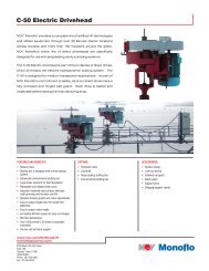
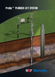
Two Run Insertable PC Pump<br />
NOV Monoflo has an innovative, new insertable progressing cavity pump design that allows the<br />
customer to insert a pc pump inside the production tubing and pressure test the tubing string with<br />
one easy to use tool.<br />
Features and Benefits<br />
• There is no need for a service rig to<br />
pull the production tubing to change a<br />
downhole pump<br />
• Pump changes can be done with a flushby<br />
equipped for rod handling<br />
• The unit minimizes the need to remove<br />
production tubing, reducing the cost of<br />
downhole gauge installations<br />
• Allows for pressure testing the<br />
production tubing as well as the primary<br />
seal, while inserting the stator.<br />
• The system has the ability to use any<br />
progressing cavity pump without<br />
performing any modifications.<br />
• The system can pull the rotor out of the<br />
well bore without unseating the primary<br />
seal.<br />
Mechanically Bonded Stator<br />
Well temperatures can increase due to natural conditions and the use of<br />
thermal stimulation techniques. These conditions challenge the viability of<br />
the traditional chemically bonded pc pump stator.<br />
One way to address this challenge is through new methods of anchoring the<br />
elastomers into the stator tube. NOV Monoflo has developed elastomeric<br />
stator technology to meet demands of high temperature wells.<br />
The mechanically bonded stator is comprised of 3 main components (not<br />
including the elastomer):<br />
• Stator Tube<br />
• Mechanical Bond Inserts<br />
• End Caps<br />
Available in two elastomer grades:<br />
• OBX suitable for temperatures up to 110° C<br />
• OC suitable for temperatures up to 150° C<br />
Available sizes:<br />
D32-900 (1 raw) D96-1040 (2 raw) D54-1800 (3 raw)<br />
D44-900 (1 raw) D150-300 (1 raw) D64-1560 (3 raw)<br />
D54-1200 (2 raw) D32-1800 (2 raw) D96-1560 (3 raw)<br />
D64-1040 (2 raw) D44-1800 (2 raw) D150-600 (2 raw)<br />
Rotor<br />
Operating<br />
Position<br />
Insert Tool<br />
Seating Nipple<br />
Insert<br />
Position<br />
Stator<br />
Tag-Bar<br />
Torque Anchor<br />
Seating Mandrel<br />
with Primary Seal
NO-GO Tag Progressing Cavity Pumps<br />
The NO-GO Tag system is a new advanced generation tool for rotor placement in progressing cavity<br />
pumps. It provides all the functionality of a traditional bottom tag bar system with the following<br />
advantages.<br />
Features and Benefits<br />
• Tags within the stator, leaving intake free of obstruction, allowing rotor to agitate solids<br />
• Coilable through the pump by only pulling up polish rod<br />
• Protects top end of stator elastomer by guiding coil entry through the pump<br />
• Positive tag for proper rotor placement by guiding rotor through timed helical tag passage into<br />
stator elastomer<br />
• Unique integrated design eliminates flow losses and extra connections<br />
• Tags using a conventional rod box<br />
• Ability to land pump lower in well<br />
• Eliminates costly mechanical tools below the pump while maintaining circulation clean-out<br />
capabilities<br />
Application<br />
• Medium to heavy oil<br />
• Wells producing solids (sand, coal fines, pyrite, etc.)<br />
• Wells with history of intake plugging<br />
• Wells with minimal cellar<br />
Charge Pumps<br />
Problem wells that produce slug sand, water, and/or gas can benefit from the use of a Charge Pump. These<br />
pumps have 3 main parts:<br />
• Production Pump - determines your lift capacity and final volume.<br />
• Pup Joint - usually located between the two pumps and has additional holes or slots depending on the<br />
application.<br />
• Charge Pump - higher volume, lower pressure pump that maintains consistent wellbore fluid by mixing it<br />
before entering the production pump.<br />
Charge Pumps<br />
Production Pump 10 15 24 32 40 44 54 64 70 80 96 120 150<br />
Charge Pump 10 40 or 24 40 96 40 96 150<br />
Specialty Components<br />
• Perforated Stator - High Gas Rate Applications<br />
• Hollow Rotor - Breaking up solids at intake<br />
NO-GO Tag Insert<br />
Bottom or Top View<br />
www.nov.com/ArtificialLift<br />
MonofloALS@nov.com
<strong>PROGRESSING</strong> <strong>CAVITY</strong> <strong>PUMP</strong> <strong>SYSTEMS</strong><br />
Hydraulic Driveheads<br />
HTD<br />
NOV Monoflo’s HTD hydraulic drivehead utilizes a bent axis motor that is<br />
coupled to a hollow shaft bearing box by a belt and pulley system, which<br />
transfers torque to the polished rod. Backspin is controlled through the<br />
hydraulic system. The motors are available in a variety of displacements to<br />
accommodate a wide variety of speeds and torques.<br />
Features and Benefits of the HTD Hydraulic Drivehead<br />
• Motor is available in various displacements<br />
• Standard synchronous belt and sheave system<br />
• Fully enclosed hinged belt guard<br />
CG-33<br />
Each model of the NOV Monoflo CG-33 hydraulic drivehead is a beltless top drive using<br />
gears to transfer torque to the polished rod. The precision ground gears reduce<br />
noise levels by up to five times in comparison to conventional belt drives,<br />
making the CG-33 drivehead an ideal solution for use in populated areas. Each<br />
CG-33 drive utilizes a radial piston motor designed to reduce internal friction<br />
and run efficiently. These driveheads are fitted with a hydraulically activated<br />
stuffing box that can withstand any progressing cavity pumping application.<br />
Features and Benefits of the CG-33 Hydraulic Drivehead<br />
• Enclosed gear housing eliminates need for belts, thus reducing field<br />
maintenance<br />
• Case hardened and precision ground gears drastically reduce noise levels.<br />
• Gear drive utilizes a radial piston motor connected to the input gear, and<br />
is available in various displacements<br />
• Pressurized stuffing box prevents fluid from entering the seal chamber<br />
extending the life of the seals<br />
• Built in polished rod vise allows stuffing box seal change without removal of<br />
drivehead or flush-by rig<br />
Technical Specifications<br />
Model HTD CG-33<br />
Max. System Pressure 3600 psi (245 kPa) 3500 psi (24,132 kPa)<br />
Max. System Temperature¹ 175 °F/ 80 °C 176 °F/80 °C<br />
Polish Rod Size 1¼" (32 mm) 1¼" (32 mm)<br />
Wellhead Connection 2d” EUE Pin or 38-3000<br />
psi-R31 Flange<br />
Thrust Bearing² Ca90-25,000 lbs /<br />
ISO-96,300 lbs<br />
Backspin Control Check valve on pressure side of<br />
the motor.<br />
Torque Control Adjustable pressure<br />
compensator on pump.<br />
38”-3000 psi-R31 Flange<br />
Ca90-33,500 lbs /<br />
ISO-129,000 lbs<br />
Check valve on pressure side of<br />
the motor.<br />
Adjustable pressure<br />
compensator on pump.<br />
Model HTD CG-33<br />
Variable Speed Control Adjustment knob on the pump. Adjustment knob on the pump.<br />
Height Integral 31" (787 mm) 31" (787 mm)<br />
Height Retrofit 47" (1194 mm) N/A<br />
Width 29" (737 mm) 24" (610 mm)<br />
Weight Integral 400 lbs (181 kg) 240 lbs (109 kg)<br />
Weight Retrofit 450 lbs (204 kg) N/A<br />
HTD Hydraulic Drivehead<br />
CG-33 Hydraulic Drivehead<br />
Bearing Box Grease Chevron Delo Grease EP NLGi2 1 tube (Chevron Ulti-Plex<br />
Synthetic Grease)<br />
¹ Maximum operating temperature may be limited by hydraulic oil. ² Ca90 load rating is for 90 million revolutions at 500 rpm. Reducing load by 50% increases life 10 times. Reducing speed by 50% doubles hours of life.
Electric Driveheads<br />
NOV Monoflo provides a complete line of Electric Driveheads for all your production<br />
needs.<br />
Features and Benefits<br />
• Robust frame<br />
• Detachable stuffing box<br />
• Operator-friendly guards and motor adjustments<br />
• Easy-to-adjust door for simple belt tightening<br />
• Accessible fill/drain spouts for easy oil changes<br />
• Bearing box is designed with a three-bearing system (Models C-50, C-60, C-80,<br />
and C-33M)<br />
• Hollow shaft bearing box (Model N-25)<br />
• Hydrodynamic brake (Models C-50, C-60, C-80, and C-33M)<br />
• Hydraulically actuated caliper disc braking system (Model N-25)<br />
• Brake reservoir for heat dissipation (Models C-50, C-60, C-80, and C-33M<br />
• Service and technical support<br />
Technical Specifications<br />
Model C-50 C-60 C-80 C-33M N-25<br />
Drive Type Direct Direct Direct Direct Direct<br />
Shaft Type Hollow Hollow Hollow Hollow Hollow<br />
Drive Style Bearing Box Bearing Box Bearing Box Bearing Bearing Box<br />
Input Style Vertical Vertical Vertical Vertical Vertical<br />
Drive Ratio 1:1 1:1 1:1 1:1 1:1<br />
Backspin Control<br />
Ratings<br />
Hydrodynamic Hydrodynamic Hydrodynamic Hydrodynamic Caliper Disc<br />
Max. Output Torque 2000 ft-lbs (2712 Nm) 2500 ft-lbs (3390 Nm) 3500 ft-lbs (4745 Nm) 1575 ft-lbs (2135 Nm) 600 ft-lbs (813 Nm)<br />
Thrust Bearing 195,000 ISO lbf 227,000 ISO lbf 310,000 ISO lbf 45,100 ISO lbf 96,300 ISO lbf<br />
Thrust Bearing¹ 50,500 Ca90 lbf 59,000 Ca90 lbf 80,400 Ca90 lbf 33,000 Ca90 lbf 25,000 Ca90 lbf<br />
Maximum Speed 600 rpm 600 rpm 600 rpm 600 rpm 500 rpm<br />
Horsepower Rating² 20 - 100 80 - 150 120 - 300 10 - 60 10 - 20<br />
Frame Type Single Motor Dual Motor Dual Motor Single Motor Single<br />
Polish Rod Size<br />
1¼” or 1½”<br />
(32mm or 38 mm)<br />
1½” (38 mm)<br />
1¼” or 2”<br />
(38 mm or 51mm)<br />
1¼” (32 mm) 1¼” (32 mm)<br />
Max. Operating Temp. 212°F / 100°C 212°F / 100°C 212°F / 100°C 428°F / 220°C 180°F / 80°C<br />
Dimensions<br />
Height with Retro. Stuffing Box 50” (1270mm) 55” (1397mm) 64” (1626mm) 44” (1118mm) 34” (864mm)<br />
Width 35” (889mm) 41” (1041mm) 42” (1067mm) 35” (889mm) 30” (762mm)<br />
Input Shaft Size 3¼” (83 mm) 3¼” (83 mm) 4¼” (108mm) 3¼” (83 mm) 2½” (64 mm)<br />
Weight 1350 lbs (612kg) 1700 lbs (771kg) 2100 lbs (953kg) 1350 lbs (612kg) 600 lbs (272kg)<br />
¹ Ca90 load rating is for 90 million revolutions. Reducing load one half increases life 10 times. Reducing rpm by one half doubles hours of life.<br />
² Maximum HP rating based on frame size only. Care must be taken in selecting motor and sheave combinations to ensure input rod torque is not exceeded.<br />
N-25 Electric Drivehead<br />
C-33M Electric Drivehead<br />
C-50 Electric Drivehead<br />
C-60 Electric Drivehead<br />
C-80 Electric Drivehead<br />
www.nov.com/ArtificialLift<br />
MonofloALS@nov.com
<strong>PROGRESSING</strong> <strong>CAVITY</strong> <strong>PUMP</strong> <strong>SYSTEMS</strong><br />
Leak Free Stuffing Box<br />
The NOV Monoflo Leak Free (LF) stuffing box is a pre-built assembly that has been exclusively<br />
designed to simplify monitoring seal wear. It consists of a double mechanical seal supplied<br />
in a single sealed cartridge.<br />
Features and Benefits<br />
• Designed with a two bearing system consisting of seal bearings designed to be<br />
in one cartridge for easy replacement which results in less downtime during<br />
maintenance<br />
• Can be mounted directly on drivehead with or without a booth<br />
• Utilizes a double mechanical seal supplied as a sealed cartridge, to deliver extended periods of leak free<br />
operation and contains any leaked fluid inside the unit<br />
• Double sealing mechanism performs an improved sealing function.<br />
• Easy fitting of the cartridge arrangement with no setting requirement normally associated with conventional<br />
mechanical seals; seal abuts bearing to set working length<br />
• Positive drive from the spindle via key through sleeve of the mechanical seal<br />
• All sealing faces are made from solid material for increased pressure and thermal stability<br />
• Equipped with a leakage detection unit which provides a visible indication to any breach of the primary seal<br />
and also ensures barrier fluid lubrication of the seal faces for maximum durability<br />
• The leakage detection unit can be reset after seal replacement<br />
Hydrodynamic Brake<br />
The Hydrodynamic Brake consists of a stationary half (stator) and<br />
a rotary half (rotor). The stator is bolted into the housing and the<br />
rotor is coupled to the shaft. During normal operation the rotor spins<br />
freely. When the unit goes into backspin, the rotor begins to rotate<br />
in the counter clockwise direction. The working fluid is then forced<br />
to the outside of the rotor and creates a circular flow path inside the<br />
brake cavity. As the energized fluid from the rotor comes into contact<br />
with the stationary fins of the stator, the energy is transferred to the<br />
stator and then back to the working fluid as heat. A small amount of<br />
working fluid is continually removed from the system and replaced<br />
with new fluid. The working fluid contained in the drivehead reservoir<br />
is used as the braking medium, which allows the energy stored in the<br />
fluid column and rod string to safely dissipate without the drivehead<br />
reaching excessive backspin speeds.<br />
Features and Benefits<br />
• Non-friction brake eliminates wear on brake components<br />
• Brake capable of 2000 ft-lbs resisting torque at 250 hp<br />
• Reliable and repeatable braking<br />
• Backspin energy is absorbed by the working fluid<br />
• Heat generated by braking is dissipated by the fluid reservoir<br />
• Consistent braking with minimal maintenance throughout the<br />
drivehead’s life<br />
Brake Stator<br />
Brake Rotor<br />
Hydrodynamic Brake Curves
VFD Controller<br />
The NOV Monoflo Progressing Cavity Pump Controller provides a<br />
number of features specifically designed for operation of progressing<br />
cavity pumps. The drive combines motor and pump control into a<br />
single, compact package that increases production, improves energy<br />
efficiency and enhances the reliability of both new and existing<br />
pumping systems.<br />
Multiple Constraint Optimization<br />
At any instant during the life of a well, there is a single constraint<br />
that limits production. Production can be maximized without<br />
compromising efficiency or reliability by forcing the system to<br />
operate at the constraint limiting production at each instant of time.<br />
Determining the applicable limits and moving smoothly between<br />
them in real time is a key advantage of the system. Models of all<br />
the system elements are run in real time at the wellhead to detect<br />
appropriate limits and enforce associated control strategies. At<br />
different points in time, the system may be limited by motor voltage,<br />
motor current, motor speed, motor torque, motor thermal capacity,<br />
power demand, rod string torque, flow line pressure, fluid level, or<br />
well inflow. Multiple constraint optimization is particularly beneficial<br />
in applications with variable inflow conditions, such as those found in<br />
coal-bed methane, high gas/oil ratio, and thermally stimulated wells.<br />
Sensorless Operation<br />
The drive uses a number of unique methods for precisely determining<br />
performance parameters from models of the pumping system<br />
elements without requiring external surface or downhole sensors.<br />
Sensorless system variables including rod speed, rod torque, pump<br />
speed, pump torque, fluid flow, fluid level, suction pressure, discharge pressure, and differential pressure can be<br />
observed through the drive keypad/display or recorded as circle charts and time-based plots. Fluid level, pump flow,<br />
and total production are displayed in selectable engineering units.<br />
Sophisticated Modeling<br />
Embedded mathematical models of the drive, motor, drive head, rod string, pump, flow line, tubing, casing, fluid, and<br />
reservoir use component specifications and well completion information along with field setup parameters to monitor<br />
pumping system operation. Identification routines automatically determine installation-dependent system parameters<br />
including those of the motor, rod string, and pump. The models capture the thermal, mechanical, electrical, and<br />
hydraulic behavior of the system to control the pumping process with greater precision than ever before.<br />
Pump Speed Control<br />
The drive provides a number of options for manual, remote, and automatic control of pump speed. Speed commands<br />
can be selected from a number of sources including potentiometer adjustments, keypad presets, serial data<br />
communications, and internal optimization controllers. The motor can be operated up to twice base speed at constant<br />
power. This allows the overall gear ratio to be increased, thereby providing increased low-speed torque without loss<br />
of maximum pump speed. Dual motors can be controlled from a single drive for operation of large pumps. The system<br />
can be configured for optimization of fluid production, gas production, energy efficiency, and/or power flow.<br />
www.nov.com/ArtificialLift<br />
MonofloALS@nov.com
Corporate<br />
Headquarters<br />
7909 Parkwood Circle Drive<br />
Houston, Texas 77036<br />
United States<br />
Phone: 713 375 3700<br />
Fax: 713 346 7687<br />
Sales<br />
8708 West Little York Road<br />
Suite 100<br />
Houston, Texas 77040<br />
United States<br />
Phone: 281 854 0300<br />
Fax: 281 854 0301<br />
<strong>National</strong> <strong>Oilwell</strong> <strong>Varco</strong> has produced this brochure for general information only, and it is not<br />
intended for design purposes. Although every effort has been made to maintain the accuracy and<br />
reliability of its contents, <strong>National</strong> <strong>Oilwell</strong> <strong>Varco</strong> in no way assumes responsibility for liability for any<br />
loss, damage or injury resulting from the use of information and data herein. All applications for the<br />
material described are at the user’s risk and are the user’s responsibility.<br />
All brands listed are trademarks of <strong>National</strong> <strong>Oilwell</strong> <strong>Varco</strong>.<br />
One Company . . . Unlimited Solutions<br />
Downhole Solutions<br />
Drilling Solutions<br />
Engineering and Project Management Solutions<br />
Industrial Solutions<br />
Lifting and Handling Solutions<br />
Production Solutions<br />
Supply Chain Solutions<br />
Tubular and Corrosion Control Solutions<br />
Well Service and Completion Solutions<br />
MonofloALS@nov.com www.nov.com<br />
© 2012 <strong>National</strong> <strong>Oilwell</strong> <strong>Varco</strong><br />
D392004432-MKT-001 Rev. 02