CN07 Multipole Connectors - AP Technology
CN07 Multipole Connectors - AP Technology
CN07 Multipole Connectors - AP Technology

Create successful ePaper yourself
Turn your PDF publications into a flip-book with our unique Google optimized e-Paper software.
general index<br />
introduction to the catalogue<br />
page<br />
● general overview of the production of multipole connectors for industrial purposes 3 - 7<br />
● general features of multipole connectors 8 - 9<br />
● standards governing the use of multipole connectors 10 - 12<br />
● features of inserts for multipole connectors 13 - 17<br />
● conductor connections 18 - 20<br />
● enclosure versions 21 - 23<br />
● enclosure and inserts combinations 24 - 27<br />
● inserts load curves 28 - 35<br />
● applications for higher voltages (CD page 38), (CDD page 52), (CQE page 73)<br />
index<br />
multipole inserts<br />
page<br />
● CK - CKS types 3 and 4 poles (10A) 36 - 37<br />
● CD types 7, 8, 15, 25, 40, 50, 64, 80, 128 poles (10A) 38 - 47<br />
● CT - CTS types 40 and 64 poles (10A) 48 - 51<br />
● CDD types 24, 38, 42, 72, 76, 108, 144, 216 poles (10A) 52 - 60<br />
● CQ types 12 poles (10A), 5, 8 poli (16A), 4+2 poles (40/10A) 61 - 65<br />
● CDA - CDC types 10, 16, 32 poles (16A) 66 - 71<br />
● CQE types 10, 18, 32, 46, 64, 92 poles (16A) 73 - 79<br />
● CN - CCE - CNE - CSE - CSS types 6, 10, 16, 24, 32, 48 poles (16A) 80 - 103<br />
● CT - CTE - CTSE types 6, 10, 16, 24 poles (16A) 104 - 113<br />
● CMSE - CMCE - CME types 3+2, 6+2, 10+2, 12+4, 20+4, 16+2, 32+4 poles (16A) 114 - 125<br />
● CP types 6, 12 poles (35A) 127 - 128<br />
● CX types 8/24 poles (16/10A), 6/36 and 12/2 poles (40/10A), 4/0, /2, /8 poles (80/16A) 129 - 133<br />
● MIXO types 12P (10A), 5P, 6P, 8P e 20P (16A), 2P and 3P (40A), 2P (100A), 1+1P and 4+4P (BUS-10A), 134 - 151<br />
1+4 and 2+8P (RJ45-10A), 2P (16A) for high voltage, 2 and 3 pneumatic contacts, frames for inserts<br />
enclosures for inserts<br />
page<br />
● CK and MK types size “21.21” 153 - 158<br />
● CQ types size “32.13” 160 - 161<br />
● CZ - MZ - MF types size “49.16” 162 - 165<br />
● CZ - MZ - MF types size “66.16” 166 - 169<br />
● CH - CA and MH - MA - MF types size “66.40” 171 - 174<br />
● CH - CA and MH - MA - MF types size “44.27” 176 - 182<br />
● CH - CA - CM - CMA and MH - MA - MM - MMA - MMF types size “57.27” 184 - 196<br />
● CH - CA - CM - CMA and MH - MA - MM - MMA - MMF types size “77.27” 198 - 210<br />
● CH - CA - CM - CMA and MH - MA - MM - MMA - MMF types size “104.27” 212 - 224<br />
● CH and MH - MF types size “77.62” 226 - 230<br />
● CH and MH - MF types size “104.62” 232 - 234<br />
1
general index<br />
index<br />
supports, special enclosures and accessories<br />
● special enclosures with dual outlets, widened, w/o outlets, for ribbon cables, for round cables, coupling, central lever 236 - 243<br />
● CG and MG types, high IP68 protection rating enclosures 244 - 252<br />
● T-BOX coupling with 1 or 2 branches 254 - 255<br />
● COB type mountings for panels 256 - 260<br />
● miscellaneous auxiliaries and accessories 262 - 263<br />
● PCB interfaces 264<br />
● Constantan (CuNi) and iron (Fe) crimping contacts 265<br />
● anchors for cables inside and outside enclosures, coding pins 266 - 271<br />
● CKM T terminal connector 272<br />
● insert joining block, metal replacement handles, carrying cover, enclosure removal pliers 273 - 274<br />
● SUB-K insert plates, control equipment kits, plate only (SDS) and plate with enclosure (CHSDS) 275 - 276<br />
● blanking or adapter plates, pliers for MIXO BUS connectors removal 277<br />
● adapters for RJ45 connectors, coupling for RJ45 connector 278 - 279<br />
● connectors for compliance with DESINA ® standard 280 - 291<br />
page<br />
crimping tools<br />
page<br />
● crimping concept 293 - 295<br />
● manual tools 296 - 303<br />
● pneumatic tools 304 - 307<br />
● wire stripping - crimping machine 308 - 309<br />
● RJ45 crimp tool 310<br />
Part Nos. and index<br />
page<br />
● Part Nos. list 312 - 322<br />
2
general overview of the multipole connector production for industrial purposes and accessories<br />
Inserts<br />
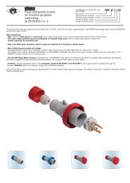
The inserts are made of self-extinguishing thermoplastic resin UL 94 V0, normally used for applications in a maximum ambience temperature of 125 °C. The special<br />
versions for use with a maximum ambience temperature of 180 °C are made of PPS. Different conductor connection techniques are available: screw connections, crimp<br />
connections, or flexible spring connections. The contacts are in silver or gold plated brass. The inserts are numbered on both sides by laser printing or moulded.<br />
There is a large number of versions of inserts selected on the basis of the rated voltage (from 50V to 5000V), the rated current (from 10A to 100A max), the number of<br />
poles, the different load combinations required (power and signal poles within the same insert).<br />
The inserts are approved in conformance with the major conformity marks including E.<br />
general<br />
The RoHS (2002/95/EC) and RAEE (2002/96/EC) Directives<br />
● The RoHS 2002/95/EC Directive bans the use of some harmful substances used in new electrical and electronic equipment commercially available from the 1st of July<br />
2006 (the exceptions for some applications are enclosed in the Directive Enclosure and in some later decisions made by the EU Commission 1)). The banned and/or<br />
restricted substances are: Lead, Mercury, Cadmium, Hexavalent Chromium, Poly-Brominated By-Phenyls and Poly-Brominated Dy-Phenyl Ethers (PBB and<br />
PBDE respectively, fire retardant substances for thermoplastic materials).<br />
● The RAEE 2002/96/EC Directive (with its later amendment 2003/108/EC) aims to recycle and reduce the waste produced by electrical and electronic equipment. It also<br />
promotes recycling and reusing such technological waste and establishes ambitious recovery rate targets, which vary according to the types of products involved. The<br />
manufacturers or their agents in the EU must ensure that the equipment sold after the 13th of August 2005 listed in the Enclosure I A and illustrated in the Enclosure I B<br />
of this Directive is collected, treated and recycled (the deadline varies from country to country. In Italy, the deadline has been postponed to 31/12/2007, awaiting for<br />
approval by the required executive Ministerial Decrees).<br />
As a manufacturer of electrical equipment and components for industrial use, I.L.M.E. acknowledges the regulations introduced by these Directives. The above mentioned<br />
Directives are already effective in almost all EU countries. For the products described in this Catalogue, although the usage restriction of the above mentioned<br />
hazardous substances is not legally applicable (none of our product does in fact belong to any of the categories described and illustrated in the RoHS and RAEE<br />
Directives), the “RoHS compliance” may become important and many of our customers may require its compliance. We have therefore carried out the corrective actions,<br />
which have led to the “RoHS compliance” of all our products, wherever required. I.L.M.E. products sold after the 1st of July 2006 do not contain any of the restricted<br />
substances in higher concentration than those allowed by the RoHS directive and by the later associated Decisions taken by the EU Commission.<br />
1) At the time of publication of this Catalogue, the following EU Commission Decisions were available: 2005/618/EC, of 18 August 2005, 2005/717/EC, of 13 October<br />
2005, 2005/747/EC, of 21 October 2005, 2006/310/EC, of 21 April 2006, 2006/690/EC, 2006/691/EC, 2006/692/EC, of 12 October 2006.<br />
The heavy duty multipole connectors for industrial purposes are used in electric and electronic machinery, control units, electric panels, control<br />
equipment and wherever connections are required for power and signalling circuits. (N.B. the connectors must not be handled live).<br />
The connectors are in conformance with the standard DIN VDE 0627 (European standard IEC 61984) and where applicable, to the standard DIN<br />
43652 (European standard EN 175301-801 developed by CENELEC TC48B).<br />
3
general overview of the multipole connector production for industrial purposes and accessories<br />
Fire Safety Standards for the railway industry<br />
general<br />
The most advanced fire safety standards for the railway industry are the French standards:<br />
- NF F 16-101 Matériel roulant ferroviaire – Comportement au feu – Choix des matériaux<br />
- NF F 16-102 Matériel roulant ferroviaire – Comportement au feu – Choix des équipements électriques<br />
which, in turn, refer to the test methods described in the following standards:<br />
- NF X 70 100 Analyse de gaz de pyrolyse et de combustion<br />
- NF X 10 702 Détermination de l'opacité des fumées en atmosphère non renouvelée<br />
the latter being very similar in methods to the following American standards:<br />
- ASTM E 662 Standard Test Method for Specific Optical Density of Smoke Generated by Solid Materials<br />
- ASTM E 162 Standard Test Method for Surface Flammability of Materials Using a Radiant Heat Energy Source.<br />
Equally as popular is the use of Bombardier Transportation toxicity specifications:<br />
- SMP 800-C Toxic Gas Generation.<br />
In Italy, since 2006, for installation on board of rolling-stocks, certification of conformity to the new Italian railway standards (listed below) is required:<br />
- UNI CEI 11170-1:2005 Trains and trams – Fire safety guidelines for trains, trams and guide vehicles – General principles<br />
- UNI CEI 11170-2:2005 Trains and trams – Fire safety guidelines for trains, trams and guided vehicles – Design recommendations – Fire containment measures –<br />
Indication, monitoring and evacuation systems<br />
- UNI CEI 11170-3:2005 Trains and trams - Fire safety guidelines for trains, trams and guided vehicles – Assessment of effect of fire on materials – Acceptable limits<br />
published by UNI and CEI together on 30/11/2005, in the delayed completion of the European standard relating to the effect of fire on materials to be installed on board<br />
of rolling-stocks, standard EN 45545, divided in 8 sections, only some of which have recently been published, after 16 years in the making, whilst the most crucial sections<br />
are still unfinished due to disagreements between the member countries (because of strong national interests, protectionism of domestic industries) especially in<br />
France, Germany, United Kingdom and Italy.<br />
To date, this planned standard, to be published as a simple TS (Technical Specification) and to be complied with on a voluntary basis, cannot yet be used and, as for the<br />
implementation of the Directives for the railway industry (interoperability of high-speed and conventional railways), the current national standards in force in the single EU<br />
member states are regarded as equivalent in terms of safety.<br />
For Italy, the requirements for materials relating to electrical connectors are contained in the 2nd schedule “Acceptability criteria for electrical and electronic materials and<br />
components” at the application “All other applications including inflammable materials” (all applications other than electric cables). For these applications, four tests are<br />
required to be carried out on the materials:<br />
- The materials being affected by a small flame according to EN ISO 11925-2 with, according to the risk levels, for LR1 and LR2, a resistance to fire of the material of<br />
15s; for LR3 and LR4, a resistance of 30s.<br />
- Smokiness in compliance with French standard NF F 16-101 with IF better or equal to F2 for all risk levels. The material we use is classified as F1 (better than F2)<br />
according to the tests we carried out.<br />
- Fume optical density measurement, in compliance with French standard NF X 10-702 (from NF F 16-101) with values ≤ 100 for all risk levels LR1…4.<br />
- Toxicity measurement, in compliance with Italian standard CEI 20-37/7, with T ≤ 2 for all risk levels LR1…4.<br />
Tests<br />
In 2006, we carried out laboratory tests approved by the French Railways SNCF, according to the above mentioned French standards NF F 16-101 and NF F 16-102, the<br />
material we use in our connectors, which has been found to belong to class F1 (Index Fumée I.F. ≤ 20) as well as a toxicity index (Index Toxicité Fumée) I.T.C. = 20.<br />
Both these values meet the requirements set out by the French standards and by the Italian standard UNI CEI 11170-3 schedule 2, which relates to electrical connectors.<br />
We have also commissioned a qualified North American laboratory to carry out tests compliant with American standards, which have confirmed compliance with the<br />
requirements set out by the US Federal Transit Administration “Recommended Fire Safety Practices for Rail Transit Material Selection” for methods ASTM E 662 (NFPA<br />
258) (fume specific optical density), ASTM E 162 (ASTM D3635) (surface inflammability flame propagation index) and Bombardier Transportation SMP 800-C (fumes<br />
and gases toxicity).<br />
Test reports are available on request (please contact our Sales Offices).<br />
All requirements have been met.<br />
The connectors are suitable for use with alternate or direct current and facilitate the manufacture of sectional electric parts in complex machinery<br />
and installation and maintenance, in conformity with the European standard EN 60204-1. The connectors are designed for heavy duty industrial<br />
applications. The approved method of mounting inserts is by fixing the four screws in an ILME enclosure or housing. ILME will not be responsible<br />
for any different mounting applications. It is the responsibility of the installer to ensure the correct coupling and earth contact of the inserts.<br />
4
Enclosures<br />
A large number of enclosure versions are available with different combinations of component materials, each one suitable to a specific installation: normal environmental<br />
conditions, high temperature environments, aggressive environments and environments that require electromagnetic compatibility. The principal parts are made in die cast<br />
aluminium alloy with a coating of epoxy-polyester powder or in self-extinguishing thermoplastic (CK and MK series). They are resistant to impacts and strong mechanical<br />
stress. The coupling stability and protection against accidental opening are assured by single or double closing devices comprising levers, springs and pegs in stainless<br />
steel or entirely in plastic (CK and MK series). Sealing is assured by special gaskets that protect the contact groups inside the enclosures against dust and aggressive<br />
agents. In general, the coupled enclosures with the appropriate connections guarantee an IP66 (EN 60529) degree of protection. Furthermore, the majority of<br />
enclosures successfully complete the high pressure hot water jet test required by standard DIN 40050 - 9 with IP69K classification. A special, IP68 protection rated series<br />
is also available.<br />
general<br />
Our enclosures have been certified by UL as Recognised Components for the USA and Canada (E mark) as accessories of our set of UL and CSA certified connector<br />
inserts (file UL E115072, file CSA 082270_0_000).<br />
The certification has been achieved by successfully completing several tests carried out in compliance with standard ANSI/UL 50 (Enclosures for Electrical Equipment)<br />
which is equivalent to the North American voluntary standard NEMA 250 (NEMA = National Electrical Manufactures Association) and to the equivalent Canadian standard<br />
CSA C22.2 No.94 (Special Purpose Enclosures) for safety levels used in North America and required by the local installation codes (ex.: NFPA 70 National Electrical Code<br />
in the US, CSA system standards for Canada); more specifically:<br />
- Type 12 (= NEMA 12): for indoor use, similar to IP54 protection rating in compliance with standard IEC/EN 60529;<br />
- Type 4 (= NEMA 4): for outdoor and indoor use, similar to IP66;<br />
- Type 4X (= NEMA 4X): for outdoor and indoor use, such as Type 4 + corrosion resistant, similar to IP66 protection rating.<br />
The certification includes all the enclosures belonging to the Standard (grey), W (green), R (red), S (EMC) and G (IP68) series of all sizes, with Pg, ISO and NPT cable<br />
entries, all special versions referable to standard types, as well as CKA enclosures.<br />
For further information, please contact I.L.M.E. SpA.<br />
5
general overview of the multipole connector production for industrial purposes and accessories<br />
Supports, special enclosures and accessories<br />
The supports, special enclosures and accessories provide the solution to the most diverse installation needs.<br />
The extensive range of articles comprises: panel supports for inserts, special enclosures (housing with double outlet, wide housings, housings without<br />
outlets (to be punctured, housings for round cables, hoods), insert combination blocks, accessories for CT inserts, interface for printed circuits, kits<br />
for control equipment, plates for mounting D-SUB inserts onto enclosures, reducing plates and closure plates, protection lid for transportation, code<br />
pins.<br />
general<br />
6
Tools<br />
To guarantee the efficiency and security of the connections a complete series of specific tools is available for contact crimping that assure the<br />
maximum quality standards required by the standards.<br />
Manual or automatic pneumatic tools for heavy production are available, together with a complete series of complementary tools for the mounting<br />
and dismounting of the contacts to be crimped.<br />
general<br />
7
general features of multipole connectors for industrial purposes<br />
<br />
general<br />
<br />
<br />
<br />
<br />
<br />
<br />
<br />
<br />
<br />
<br />
<br />
<br />
<br />
8
general features of multipole connectors for industrial purposes<br />
Threaded cable passage in various Pg diameters<br />
(types with pre-code ”C”) or metric<br />
passage (types with pre-code ”M”) in<br />
accordance with EN 60423, for cable entry<br />
devices in accordance with EN 50262<br />
(NPT threading on request), may be<br />
located vertically, horizontally or frontally.<br />
Heavy duty enclosures in die-cast<br />
aluminium alloy or self-extinguishing<br />
thermoplastic (CK and MK series).<br />
cRUus (E) certified<br />
Wall mounting or bulkhead housings and<br />
hoods are available, with or without fixed<br />
covers or with mobile protection covers.<br />
The types of enclosures CH-CA (Pg cable<br />
entries) and MH-MA (metric cable entries)<br />
have a tab that prevents the insertion of<br />
inserts series CME (all) and CMCE (only<br />
16+2 poles), while CM (Pg) enclosures<br />
series and MM (metric) do not have any<br />
tabs and contain supplementary insulating<br />
strips inside.<br />
Stainless steel closure levers and springs<br />
guarantee a perfect closure and sealing.<br />
Locking device available in two versions,<br />
simple (with one lever), or double (with two<br />
levers).<br />
Various types of handles are available: in<br />
self-extinguishing, thermoplastic material<br />
reinforced with glass fibres; in die-cast<br />
aluminium (for special use with temperatures<br />
of up to 180 °C); monoblock stainless steel<br />
handles (CK, CZ, MK, MZ enclosures and<br />
for special uses with temperatures of up to<br />
180 °C).<br />
Unlosable insert fastening screws, with<br />
antiloosening flexible washer.<br />
Contacts position identified with numbers<br />
or codes on both sides of each insert and<br />
laser printed or moulded.<br />
Contacts in silver or gold-plated brass<br />
with connections to the conductors made<br />
via unlosable unloosened screws, spring<br />
terminal, crimping or incorporated 45°<br />
terminal block connectors (with screw or<br />
spring terminal).<br />
Earth terminal protection with wide contact<br />
surface.<br />
Pegs and levers supplied with anti-friction<br />
rings that facilitate closure and limit wear<br />
and tear.<br />
CE marking attesting conformity to the<br />
requirements of the Low Voltage directive<br />
73/23/EEC and its modification 93/68/EEC.<br />
general<br />
Metallic enclosures with a coated finish of<br />
epoxy-polyester with high resistance to<br />
mechanical stress and external agents.<br />
Enclosures used with temperatures of up<br />
to 180 °C and in aggressive environments<br />
are treated with special coatings. Where<br />
electromagnetic compatibility is necessary:<br />
EMC enclosures with high conductivity and<br />
high corrosion resistance surface<br />
treatment.<br />
Inserts in self-extinguishing thermoplastic<br />
material reinforced with glass fibres, UL<br />
approved, with a limit working temperature<br />
from -40 °C to +125 °C.<br />
The inserts CME (all) and CMCE (only<br />
16+2 poles) for 830V have a key that<br />
prevents the insertion of inserts for use<br />
other than that prescribed (types CM - Pg<br />
and MM - metric).<br />
For some series, inserts in PPS<br />
(polyphenylene sulphide) may be<br />
requested for special uses with temperatures<br />
of up to 180 °C.<br />
Polarized inserts with asymmetric guide<br />
rails for preventing incorrect coupling.<br />
The inserts have a mechanical duration<br />
equal to or over 500 coupling cycles.<br />
Inserts manufactured in conformity with<br />
EN 61984 (DIN VDE 0627 standard and<br />
are certified and identified with the UL<br />
and CSA marks.<br />
Special seal gaskets in vinyl nitrile elastomer<br />
or fluoro elastomer (on enclosures for use<br />
with maximum temperatures of 180 °C and<br />
for aggressive environments), in anti-aging,<br />
oil-resistant, fuel-resistant, together with<br />
the cable entry devices (not supplied)<br />
provide an IP66 degree of protection for<br />
coupled connectors.<br />
Special conductive seals for EMC enclosures.<br />
9
standards<br />
standards<br />
Dimensioning of clearances and creepage distances<br />
European standard EN 61984 Ed. 1.0 (22001-11) was recently published<br />
for safety prescriptions for multipole connectors for industrial uses and for<br />
the relevant tests. This standard assimilates, without any modifications, the<br />
corresponding international standard IEC 61984 Ed.1.0 (2001-06).<br />
It is applicable to connectors with rated voltage values of over 50V, and up<br />
to 1000V, and rated currents values of up to 125A per pole, for which no<br />
dedicated standard exists, or to which the particular specifications or the<br />
manufacturer refer as regards the safety aspects.<br />
For determining the minimum through-air and surface insulation distances,<br />
i.e. creepage distances, for connectors, this standard makes use (with some<br />
modifications) of the concepts of standard IEC 60664-1 Ed. 1.0 (1992-10) 1) .<br />
NOTE - For connectors with rated voltage values of up to 50V - excluded<br />
from the field of application of Low Voltage Directive 73/23/EEC - standard<br />
EN 61984 may be used as a guide. For surface and through-air insulation<br />
distances, refer to standard IEC 60664-1 Ed. (1992-10).<br />
We are illustrating below the method of standard EN 61984 for determining<br />
minimum insulation values in connectors. The rated characteristics for each<br />
ILME connector family are provided on pages 14 and 15.<br />
The following are now obsolete: the insulation group concept, and the<br />
distinction of rated voltage values into d.c. and a.c. voltage values 220V<br />
and 380V were adapted to standardised values 230V and 400V according<br />
to IEC 60038 (2) and some concepts were taken from the regulations for LV<br />
electrical systems of the IEC 60364 (3) series, as follows:<br />
- The overvoltage categories (I, II, III, IV), according to the use of the<br />
equipment (4) . They are correlated to the transient overvoltages taken as a<br />
basis for determining the rated impulse withstand voltage<br />
- The degrees of pollution<br />
- The classification of insulating materials according to their resistance to<br />
tracking<br />
- The conditions of the electrical field (homogenous or inhomogenous).<br />
Overvoltage categories (or impulse withstand)<br />
The overvoltage categories of a circuit or of an electrical system are<br />
identified by a conventional number (from I to IV) based on the limit or the<br />
control of the assumed transient overvoltage values obtained on a circuit or<br />
electrical system and depends on the means used to reduce the<br />
overvoltages.<br />
TABLE 1<br />
The rated impulse withstand voltage for equipment energised directly from<br />
the low-voltage mains (IEC 60664-1 Edition 1.0 1992-10)<br />
Nominal voltage of Voltage line to neutral Rated impulse withstand<br />
the supply system derived from nominal voltage b)<br />
based on IEC 60038 voltages a.c. or d.c.<br />
(CENELEC HD 472 S1, CEI 8-6)<br />
Overvoltage category<br />
V V ≤ V V<br />
Three phase a) Single phase I II III IV<br />
50 330 500 800 1500<br />
100 500 800 1500 2500<br />
120-240 150 800 1500 2500 4000<br />
230/400<br />
277/480<br />
} 300 1500 2500 4000 6000<br />
400 / 690 600 2500 4000 6000 8000<br />
1000 1000 4000 6000 8000 12000<br />
a) The "/" symbol indicates a four-wire three phase distribution system (star distribution).<br />
The lower value is the voltage between phase and neutral (phase voltage), whereas the<br />
higher value is the voltage between the phases (mains voltage).<br />
Where only one value is indicated, it refers to three-wire, three-phase systems (delta<br />
distribution) and specifies the line-to-line value.<br />
b) Equipment with these rated impulse withstand values can be used in installations in<br />
accordance with standard IEC 60364-4-443 (Italian standard CEI 64-8/4 Section 443, German<br />
standard DIN VDE 0100-443).<br />
Table 1 supplies the rated impulse withstand voltage for equipment energised<br />
directly from the low voltage mains in function of the rated voltage of the power<br />
supply system, the relative voltage line-to-neutral and the overvoltage category.<br />
Industrial machinery and installations with fixed connection to the low<br />
voltage supply system and consequently the relative components<br />
including multipole connectors, constitute an example of the equipment<br />
that belongs to the overvoltage category III.<br />
Examples of general equipment that comes under overvoltage category<br />
II are electrical household appliances, portable tools and other household<br />
equipment or similar.<br />
For distribution networks with rated voltage of 230/400V (star distribution with<br />
earthed neutral), and over-voltage category III (category III: impulse withstanding),<br />
the demanded rated impulse withstanding voltage is 4kV.<br />
For distribution networks with rated voltage of 400 or 500V (star distribution<br />
without neutral or with insulated neutral, or delta distribution, insulated or<br />
corner-earthed), and over-voltage category III (category III: impulse withstanding),<br />
the demanded rated impulse withstanding voltage is 6kV.<br />
(1) Assimilated with modifications as European Harmonisation Document HD 625.1 S1:1996<br />
and published by the CENELEC member countries as a national standard: Italian standard<br />
CEI 28-6 (1997-11), German standard DIN VDE 0110-1 (VDE 0110 Teil 1):1997-04.<br />
(2) Harminisation Document CENELEC HD 472 S1, Italian standard CEI 8-6, German<br />
standard DIN IEC 38:1987-05.<br />
(3) Italian standard CEI 64-8, German standard DIN VDE 0100.<br />
(4) HD 625.1 S1 modifies the definition to "impulse withstanding categories".<br />
Degrees of pollution<br />
Pollution indicates the presence of any kind of foreign matter, whether solid,<br />
liquid or gaseous (ionised gas) that can have a negative influence on the<br />
dielectric strength or on the surface resistivity of the insulating material.<br />
The standard establishes four degrees of pollution. The categories are<br />
identified by conventional numbers based on the quantity of polluting<br />
agents or on the frequency of the phenomenon which determines the<br />
reduction of the dielectric strength and/or of the surface resistivity.<br />
Pollution degree 1:<br />
No pollution or only dry, non-conductive pollution.<br />
The pollution has no influence.<br />
Pollution degree 2:<br />
Only non-conductive pollution except that occasionally a temporary<br />
conductivity caused by condensation may occur.<br />
Pollution degree 3:<br />
Conductive pollution or dry, non-conductive pollution which becomes<br />
conductive due to condensation which may occur.<br />
Pollution degree 4:<br />
The pollution generates persistent conductivity caused by conductive dust<br />
or by rain or snow.<br />
Pollution degree 3 is typical of an industrial environment or similar, while<br />
pollution degree 2 is typical of a household environment or similar.<br />
Standard EN 61984 permits the sizing of surface insulation distances of<br />
connectors installed in enclosures in protection class ≥IP54 for the degree<br />
of pollution immediately below that of the application environment (e.g.: 2<br />
instead of 3).<br />
Extract from standard EN 61984<br />
6.19.2.2 For a connector in protection class IP54 or higher, according to<br />
Publication IEC 60529, the insulating parts inside the enclosure may be<br />
sized for a lower degree of pollution.<br />
This applies also to coupled connectors, closure of which is ensured by the<br />
connector enclosure, and which may be uncoupled for test and maintenance<br />
purposes only.<br />
One may therefore use connectors installed in enclosures or containers in<br />
protection class ≥IP54, at the rated data referring to degree pollution 2 in<br />
industrial applications with degree of pollution 3, if, in compliance with the<br />
standard, the coupling of the connectors is opened only occasionally for<br />
tests or maintenance. In the event of temporary or limited duration in<br />
uncoupled state, a closing cover is, however, necessary, guaranteeing at<br />
least protection class IP54. However, this does not apply to connectors<br />
which remain uncoupled and exposed to an industrial atmosphere for an<br />
indefinite period. It should be noted, however, that pollution could penetrate<br />
inside coupled connectors, also when it comes from remote parts of the<br />
electrical system (e.g. through conduits providing cable entry to the<br />
connectors enclosure).<br />
Moreover, connector enclosures are usually supplied without cable entry<br />
devices, with the installer fitting such devices according to need. The<br />
degree of protection marked on the enclosures is guaranteed only for<br />
connectors coupled through the use of cable entry devices in equal or<br />
higher IP protection class and expertly installed.<br />
Examples of application for the selection of degree of pollution 2 for<br />
a connector<br />
- connector on an electric motor controller, which is uncoupled only to replace<br />
a faulty motor, also in cases where degree of pollution 3 is instead<br />
specified for the system;<br />
- connector on a module-constructed machine, which is opened only for<br />
transport purposes and which is used only for faster installation and for<br />
safer putting into service. One must make sure that the connector has not<br />
been polluted during transport. To ensure this has not occurred, protective<br />
covers or adequate packing must be used;<br />
- connector inside a panel in protection class ≥IP54. In this case one may<br />
even renounce equipping the connector with an IP54 enclosure.<br />
Insulating material<br />
Insulating material influences the determination of the minimum creepage<br />
distance. It is characterised according to the damage it suffers from the<br />
concentrated release of energy during scintillations when a surface leakage<br />
current is interrupted due to the drying of the contaminated surface.<br />
The CTI (comparative tracking index), (index of resistance to surface<br />
currents) is assumed as index of the resistance to creep currents of the<br />
insulating materials in the presence of atmospheric contaminating agents.<br />
The CTI constitutes the numeric value of the maximum voltage at which a<br />
material can resist against 50 drops of an electrolytic test solution without<br />
tracking, i.e. without a progressive formation of conductive paths on the<br />
surface of the solid insulating material (and permanent electric arc between<br />
the electrodes of the test equipment) due to the combined effect of<br />
electrical stress and electrolytic contamination.<br />
The solid insulating materials are classified into four groups:<br />
Group I 600 ≤ CTI<br />
Group II 400 ≤ CTI < 600<br />
Group IIIa 175 ≤ CTI < 400<br />
Group IIIb 100 ≤ CTI < 175<br />
The values for groups IIIa/IIIb (Table 6, EN 61984) are identical for the<br />
purpose of determining the creepage distance values.<br />
The insulating materials used to manufacture the ILME multipole<br />
connectors belong to groups IIIa / IIIb.<br />
10
standards<br />
Electric field conditions<br />
The insulation clearance is determined in Table 2 of IEC 60664-1, bearing in mind<br />
the following influencing factors:<br />
- Rated impulse withstand voltage<br />
- Electric field conditions<br />
- Altitude: the values specified in Table 2 give sufficient impulse withstand<br />
capability for equipment for use at altitudes up to 2.000 m. For equipment for use<br />
at higher altitudes, the corrective factors specified in Table A2 of IEC 60664-1<br />
- The micro-environment.<br />
The shape and arrangement of the conductive parts influence the homogeneity of<br />
the electric field and consequently the clearance needed to withstand a given<br />
voltage. The clearances in Case A (inhomogeneous field) have the required<br />
impulse withstand voltage under all conditions: clearances not less than those<br />
specified in Table 2 - Case A can be used irrespective of the shape and arrangement<br />
of the conductive parts and without verification by an impulse withstand test.<br />
Determination of clearances<br />
In accordance with standard IEC 60664-1, the following must be identified to determine it:<br />
a) The rated voltage of the power supply (usually 230/400V and therefore a<br />
conventional voltage line-to-neutral of 300V), in star distribution networks<br />
with earthed neutral, or 400V for star networks without neutral, or with<br />
insulated neutral, or in networks with the distribution transformer's<br />
secondary winding delta connected, insulated or corner-earthed and,<br />
therefore, with conventional phase voltage of 600V);<br />
b) The overvoltage category (usually III);<br />
c) The rated impulse withstand voltage determined from Table 1 of IEC 60664-1<br />
(usually 4 kV or 6kV)<br />
d) The type of electric field to which the parts through which the current flows<br />
shall be subjected (worse case = inhomogenous field) and the degree of<br />
pollution (usually 3).<br />
Standard EN 61984 specifies that the through-air insulation distance should<br />
be sized according to Table 2 of IEC 60664-1, but according to the rated impulse<br />
withstanding voltage obtained from Table 5 of EN 61984. The rated impulse<br />
withstanding voltage must be selected according to the rated power supply<br />
voltage and to the overvoltage category. The assignment of connectors to a<br />
particular overvoltage category (usually III) is effected according to the rules of<br />
IEC 60664-1.<br />
Rated voltage<br />
The voltage value assigned by the manufacturer to the connector and to which<br />
the operating and performance characteristics refer (IEC 60664-1, definition<br />
1.3.9 modified).<br />
NOTE – A connector may have more than one rated voltage value.<br />
As concerns the choice of the type of electric field, the through-air insulation<br />
distances via windows and openings in the enclosures of insulating material,<br />
must comply with the values of case A in Table of IEC 60664-1. i.e. for non<br />
uniform field conditions.<br />
TABLE 5<br />
Rated impulse withstand voltage (EN 61984 Edition 1.0 - 2001-11)<br />
Nominal voltage of the supply system<br />
Preferred values for the rated<br />
impulse withstand voltage in kV<br />
(≤ rated insulation voltage of equipment) (1.2/50 μs)<br />
Overvoltage category *<br />
I II III IV<br />
a.c. a.c. a.c. a.c.<br />
voltage voltage voltage voltage<br />
(r.m.s. (r.m.s. (r.m.s. (r.m.s.<br />
value) value) value) value)<br />
Voltage line-to-earth derived from<br />
the nominal voltage of the<br />
supply system to the a.c. voltage<br />
(r.m.s. value) or d.c. voltage<br />
d.c.<br />
voltage<br />
d.c.<br />
voltage<br />
V V V V V kV kV kV kV<br />
100 66/115 66 60 - 0.5 0.8 1.5 2.5<br />
150 120/208; 115; 120; 110; 120 220-110; 0.8 1.5 2.5 4<br />
127/220; 127 240-120;<br />
300 220/380; 220; 230; 220 440-220 1.5 2.5 4 6<br />
230/400; 240; 260;<br />
240/415; 277;<br />
260/440;<br />
277/480;<br />
600 347/600 347; 380; 480 960-480 2.5 4 6 8<br />
380/660 400; 415;<br />
400/690 440; 480<br />
415/720 500; 577;<br />
480/830 600;<br />
1000 660; 690; 1000 - 4 6 8 12<br />
720; 830;<br />
1000;<br />
* Values for voltages ≤ 50V mentioned in IEC 60664-1, Encl. B<br />
With the three values (b) (c) and (d) the minimum clearence is determined in Table 2 of IEC<br />
60664-1<br />
Special protected levels<br />
Level for electrical equipment<br />
(household and similar)<br />
Level for distribution<br />
supply systems<br />
Input level<br />
TABLE 2*)<br />
Minimum clearance for insulation co-ordination (IEC 60664-1<br />
Edition 1.0 - 1992-10)<br />
Required<br />
Minimum clearances in air in mm.<br />
impulse<br />
up to 2.000 m. above sea level<br />
withstand<br />
voltage<br />
Case A - inhomogenous field 1) Case B - homogenous field 2)<br />
degree of pollution<br />
degree of pollution<br />
kV 1 2 3 4 1 2 3 4<br />
0.33 3) 0.01 0.2 4) 5) 0.8 5) 1.6 5) 0.01 0.2 4) 5) 0.8 5) 1.6 5)<br />
0.40 0.02 0.2 4) 5) 0.8 5) 1.6 5) 0.02 0.2 4) 5) 0.8 5) 1.6 5)<br />
0.50 3) 0.04 0.2 4) 5) 0.8 5) 1.6 5) 0.04 0.2 4) 5) 0.8 5) 1.6 5)<br />
0.60 0.06 0.2 4) 5) 0.8 5) 1.6 5) 0.06 0.2 4) 5) 0.8 5) 1.6 5)<br />
0.80 3) 0.10 0.2 4) 5) 0.8 5) 1.6 5) 0.10 0.2 4) 5) 0.8 5) 1.6 5)<br />
1.0 0.15 0.2 4) 5) 0.8 5) 1.6 5) 0.15 0.2 4) 5) 0.8 5) 1.6 5)<br />
1.2 0.25 0.25 0.8 5) 1.6 5) 0.2 0.2 4) 5) 0.8 5) 1.6 5)<br />
1.5 3) 0.5 0.5 0.8 5) 1.6 5) 0.3 0.3 0.8 5) 1.6 5)<br />
2.0 1.0 1.0 1.0 1.6 5) 0.45 0.45 0.8 5) 1.6 5)<br />
2.5 3) 1.5 1.5 1.5 1.6 5) 0.6 0.6 0.8 5) 1.6 5)<br />
3.0 2 2 2 2 0.8 0.8 0.8 5) 1.6 5)<br />
4.0 3) 3 3 3 3 1.2 1.2 1.2 1.6 5)<br />
5.0 4 4 4 4 1.5 1.5 1.5 1.6 5)<br />
6.0 3) 5.5 5.5 5.5 5.5 2 2 2 2<br />
8.0 3) 8 8 8 8 3 3 3 3<br />
10.0 11 11 11 11 3.5 3.5 3.5 3.5<br />
12.0 3) 14 14 14 14 4.5 4.5 4.5 4.5<br />
1) Between pointed and flat electrode.<br />
2) When the clearance is less than the value indicated for Case A an impulse<br />
withstand voltage test certificate is required<br />
3) Preferential values specified in Table 1<br />
4) For printed wiring material, the values of degree of pollution 1 apply except that the<br />
value shall not be less than 0.04 mm as specified in Table 4<br />
5) These minimum clearances given for pollution degrees 2, 3 and 4 are based on<br />
experience rather than on fundamental data.<br />
*) Table 2 of IEC 60664-1 is modified in Variant 2. In particular, the columns referring<br />
to degree of pollution 4 have been eliminated. The definition of this degree is varied<br />
in 2.5.1 to: "permanent conductivity occurs, due to conductive dust, rain or other<br />
humid conditions". The through-air insulation distances for degree of pollution 4<br />
area as specified for degree of pollution 3, with the exception that the minimum<br />
through-air distance is 1.6 mm.<br />
In 2.5.2 it is specified that "in conductive pollution conditions, the dimensions for the<br />
surface insulation distances cannot be specified where permanent conductive<br />
pollution is present, e.g.: due to coal or metal dust. On the contrary, the insulation<br />
surface should be designed in order to prevent a seamless path of conductive<br />
pollution, e.g.: by means of ribs and cavities".<br />
The values written in bold are the most common multipole connectors for<br />
industrial purposes.<br />
If the component respects the minimum through-air insulation distance prescribed for live<br />
parts of opposing polarities, it is exempted from the impulsed voltage withstanding test.<br />
This test is run at sea level using increased voltage values in order to take into account<br />
rarefied air at high altitude (the prescribed values refer to 2000 m asl. However, if this<br />
distance is not respected, passing the test gives one the right to declare the relevant rated<br />
impulse withstanding voltage.<br />
Declaration of the rated impulse withstanding voltage is optional for standard EN 61984: if<br />
the manufacturer declares the rated impulse withstanding voltage, the impulse withstanding<br />
voltage test is, in any event, necessary as dielectric verification. Alternatively, if the<br />
manufacturer does not declare this rated value, the voltage withstanding dielectric test at<br />
mains frequencies of 50/60 Hz for 60 s (test 4a of IEC 60512) is necessary, but at reduced<br />
values compared to the peak values of the impulsive test voltages of wave shape<br />
standardised at 1.2/50 μs.<br />
To this end, standard EN 61984 provides the following cross-reference table:<br />
TABLE 8<br />
Test voltages (EN 61984 Edition 1.0 - 2001-11)<br />
Rated impulse<br />
Test voltages<br />
withstand voltage Impulse withstand * Withstand voltage<br />
kV voltage (r.m.s. value)<br />
kV (1.2/50 μs)<br />
kV (50/60 Hz)<br />
at 2000 above sea level at sea level<br />
0.33 0.33 0.35 0.23<br />
0.5 0.5 0.55 0.37<br />
0.8 0.8 0.91 0.50<br />
1.5 1.5 1.75 0.84<br />
2.5 2.5 2.95 1.39<br />
4 4 4.8 2.21<br />
6 6 7.3 3.31<br />
8 8 9.8 4.26<br />
12 12 14.8 6.6<br />
* If the test laboratory is situated between sea level and an altitude of 2000 m asl,<br />
interpolation of test impulsed voltage is allowed.<br />
Rated impulse withstand voltage<br />
The rated impulse withstanding voltage assigned by the manufacturer to the<br />
connector, which refers to the withstanding capacity of its insulation with respect to<br />
transient overvoltages [IEC 60664-1, definition 1.3.9.2 modified].<br />
Impulse withstand voltage<br />
The highest peak value of a voltage impulse of prescribed shape and polarity, which<br />
does not cause insulation faults under specified conditions.<br />
11<br />
standards
standards<br />
Dimensioning of creepage distances<br />
The minimum surface insulation distance (creepage distance), i.e. "the shortest distance along the surface of the insulation material between two<br />
conducting parts" [IE 60664-1 development 1.3.3] for connectors is prescribed by standard EN 61984 in Table 6. It is determined according to rated<br />
voltage, degree of pollution and insulating material group. The rated voltage providing access to Table 6 (rationalised voltage of the feed system) is<br />
determined in Table 3a of IEC 60664-1 for single phase two or three wire a.c. or d.c. systems or Table 3b for three-phase three or four wire a.c. systems.<br />
Usually for three-phase systems with 230V/400V reted voltage, the conventional line-to-line insulation voltage is 400V and the line-to-earth for TT or TN<br />
systems is 250V. For three-phase systems with 400V or 500V rated voltage the conventional line-to-line insulation voltage is respectively 400V and 500V.<br />
The degree of pollution must be specified according to standard IEC 60664-1. It strongly influences the rated insulation voltage of a connector. Therefore,<br />
the rated insulation voltage of a connector should be reconsidered time by time for each degree of pollution.<br />
standards<br />
TABLE 3a<br />
Single phase two or three wire a.c. or d.c.<br />
systems (IEC 60664-1 Edition 1.0 - 1992-10)<br />
TABLE 3b<br />
Three-phase three or four wire a.c. systems<br />
(IEC 60664-1 Edition 1.0 - 1992-10)<br />
Nominal<br />
voltage of the<br />
supply system* )<br />
Voltages rationalised<br />
for Table 4<br />
for insulation<br />
line-to-line 1) line-to-earth 1)<br />
A<br />
B<br />
V V V<br />
12.5 12.5 -<br />
24 25 -<br />
25 25 -<br />
30 32 -<br />
42 50 -<br />
48 50 -<br />
50 ** ) 50 -<br />
60 63 -<br />
30-60 63 32<br />
100 ** ) 100 -<br />
110 125 -<br />
120 125 -<br />
150 ** ) 160 -<br />
220 250 -<br />
110-220 250 125<br />
120-240 250 125<br />
300 ** ) 320 -<br />
220-440 500 250<br />
600 ** ) 630 -<br />
480-960 1000 500<br />
1000 ** ) 1000 -<br />
Nominal<br />
voltage of the<br />
supply system* )<br />
Voltages rationalised<br />
for Table 4<br />
for insulation<br />
line-to-line 1) line-to-earth 1)<br />
A C D<br />
V V V V<br />
63 63 32 63<br />
110 125 80 125<br />
120 125 80 125<br />
127 125 80 125<br />
150 ** ) 160 - 160<br />
208 200 125 200<br />
220 250 160 250<br />
230 250 160 250<br />
240 250 160 250<br />
300 ** ) 320 - 320<br />
380 400 250 400<br />
400 400 250 400<br />
415 400 250 400<br />
440 500 250 500<br />
480 500 320 500<br />
500 500 320 500<br />
575 630 400 630<br />
600 ** ) 630 - 630<br />
660 630 400 630<br />
690 630 400 630<br />
720 800 500 800<br />
830 800 500 800<br />
960 1000 630 1000<br />
1000 ** ) 1000 - 1000<br />
Legenda:<br />
A = All systems.<br />
B = Single phase three-wire systems with mid-point earthed.<br />
C = Three-phase four-wire systems [secondary winding of a star distribution<br />
transformer] neutral-earthed 2) .<br />
D = Three-phase three-wire systems [secondary winding of a delta distribution<br />
transformer], unearthed 1) or corner-earthed.<br />
1) The phase-earth insulation for unearthed or impedance-earthed lines is equal to<br />
that between phases, because the operating voltage of any phase can, in practice,<br />
approach full voltage between the phases [line voltage]. This is because the<br />
actual voltage to earth is determined by the insulation resistance and by the<br />
capacitive reactance of each phase to earth. Consequently, a low (but acceptable)<br />
insulation resistance of a phase can, in effect, earth it and increase voltage to<br />
earth of the other two phases at full voltage between the phases [line voltage].<br />
2) For equipment for use on both three-phase three-wire and three-phase four wire<br />
supplies, earthed or unearthed, use only the values for three-wire systems.<br />
*) Assuming a rated voltage of the equipment.<br />
**) These values correspond to the values given in Table 1.<br />
With this voltage value, the pollution degree and the materials group the minimum creepage distance can be determined using Table 6.<br />
TABLE 6<br />
Minimum creepage distances (EN 61984 Edition 1.0 - 2001-11)<br />
Rated<br />
Minimum creepage distances (mm)<br />
voltage<br />
Pollution degree<br />
r.m.s. value 1 2 3 4<br />
a.c or d.c. see note b Material group Material group Material group<br />
V I a II III I II III c I II III c<br />
63 0.2 0.63 0.9 1.25 1.6 1.8 2 2.1 2.6 3.4<br />
80 0.22 0.67 0.95 1.3 1.7 1.9 2.1 2.2 2.8 3.6<br />
100 0.25 0.71 1 1.4 1.8 2 2.2 2.4 3 3.8<br />
125 0.28 0.75 1.05 1.5 1.9 2.1 2.4 2.5 3.2 4<br />
160 0.32 0.8 1.1 1.6 2 2.2 2.5 3.2 4 5<br />
200 0.42 1 1.4 2 2.5 2.8 3.2 4 5 6.3<br />
250 0.56 1.25 1.8 2.5 3 3.5 4 5 6.3 7.5<br />
320 0.75 1.6 2.2 3.2 4 4.5 5 6 7.3 8.6<br />
400 1 2 2.8 4 4.5 5.3 6 7 8.5 10<br />
500 1.3 2.5 3.6 5 6 7 8 9 11 13<br />
630 1.8 3.2 4.5 6.3 8 9 10 11.1 13.6 16.1<br />
800 2.4 4 5.6 8 9 10.5 12 13.8 17 20.2<br />
1000 3.2 5 7.1 10 12 14 16 17 21 25<br />
NOTE 1: The values for voltages ≤ 50V are supplied in IEC 60664-1, Table 4.<br />
NOTE 2: The values in bold are reduced compared to those of Table 4 IEC 60664-1, in compliance with 2.4 of IEC 60664-1.<br />
a Materials group I or materials group II, III, where the possibility of tracking is reduced in conformance with the conditions of paragraph 3.2 of IEC 60664-1.<br />
b Materials group I, II, IIIa, IIIb<br />
c Materials group IIIb is not recommended for application with pollution degree 3 above 630V and with pollution degree 4.<br />
12
feature of inserts for multipole connectors<br />
Recommended tightening torque and size of screwdriver<br />
size of connector type tightening tightening recommended size<br />
screw torque torque of screwdriver<br />
(Nm) (Ib.in) (mm)<br />
M2.5 CT 40, 64 0.4 3.5 0.5x3<br />
M2.6 CTE 06...24 0.4 3.5 0.5x3<br />
Ø 2.9 CQ 04/2, CQ 08 0.7 6.2 Ph1<br />
M3 screw of earthing terminal series CQ 05, CQ 12 0.5 4.4 0.5x3<br />
M3 CDA 0.5 4.4 Ph0 or 0.6x3.5<br />
M3 CK, CKS, CD 07, CD 08, CQ 05, CQ 12 0.5 4.4 0.5x3<br />
M3 CN, CX 4/8 (16A) 0.5 4.4 0.6x3.5<br />
M3 CN..Q, CX 4/8 Q (16A) 0..5 4.4 Ph0<br />
M3 CNE, CME 0.5 4.4 Ph0 or 0.8x4<br />
M3 screw of small earthing terminal, MIXO frames series 0.5 4.4 Ph1 or 1.0x5.5<br />
M3 screw for fastening to enclosures, all series 0.5 4.4 Ph1 or 0.8x4<br />
M3,5 screw of earthing terminal series CDA, CDC 0.8 7.1 Ph1 or 1.0x5.5<br />
M4 screw of large earthing terminal, MIXO frames series 1.2 10.6 Ph1 or 1.0x5.5<br />
M4 CP 1.2 10.6 Ph1 or 0.8x4<br />
M4 screw of earthing terminal, all series except CDA, CDC, MIXO 1.2 10.6 Ph2 or 1.0x5.5<br />
M6 CX 4/... (80A) 2.5 22.1 1.0x5.5<br />
general<br />
Increasing the tightening torque does not improve considerably the contacts resistances. The screw torques are selected according to standard<br />
EN 60999-1, to provide excellent mechanical, thermal and electric behaviour. The conductor or terminal may be damaged if the recommended<br />
values are significantly exceeded.<br />
Stripping lenghts<br />
inserts conductor section stripping<br />
lenght<br />
connection technique (mm 2 ) (AWG) (mm)<br />
Screw<br />
CK 0.75-2.5 18-14 6<br />
CX 4/8 (16A) 0.75-2.5 18-14 7<br />
CN 0.75-2.5 18-14 7<br />
CNE 0.5-2,5 20-14 7<br />
CNE..X 0.25-2.5 24-14 7<br />
CDA 0.75-2.5 18-14 7<br />
CDA..X 0.25-2.5 24-14 7<br />
CTE 06...24 0.75-2..5 18-14 12<br />
CT 40 and 64 0.14-2.5 26-14 12<br />
CME 0.5-2.5 20-14 7<br />
CP 1.5-6 16-10 10,5<br />
CX 4/.. (80A) 4-16 12-5 14<br />
Crimp<br />
CDD, CD, MIXO (10A), CQ 12 0.14-2.5 * 26-14 8 (* 6 for 2.5 mm 2 )<br />
CCE, CDC, CMCE, CQ, CQE, MIXO (16A) 0.5-4 20-12 7,5<br />
CX, MIXO (40A) 1.5-2.5 16-14 9<br />
4-6 12-10 9,6<br />
MIXO (100A) 16-35 5-2 15<br />
Spring<br />
CSE, CTSE 06...24, CMSE, MIXO (CX 05 S), CSS 0.14-2.5 26-14 9...11<br />
CTS 40/64 0.14-2.5 26-14 9...11<br />
non-prepared non-prepared<br />
max 1 prepared max 18 prepared<br />
CKS 0.14-2.5 26-14 9...11<br />
non-prepared non-prepared<br />
max 1.5 prepared max 16 prepared<br />
13
feature of inserts for multipole connectors<br />
inserts No. of poles 1) EN 61984 (2001-11) EN 61984 (2001-11) UL/CSA certifications 3)<br />
series pollution degree 3 pollution degree 2 certification 3)<br />
general<br />
code<br />
main contacts + m<br />
auxiliary contacts<br />
rated current 4)<br />
rated voltage<br />
CK 3, 4 --- 10A 250V 4kV 3 230/400V 4kV 2 600V UL, CSA, CCC, GL<br />
CKS 3, 4 --- 10A 400V 4kV 3 600V (UL), (CSA)<br />
CD 8 (without m) --- 10A 50V 0.8kV 3 50V UL, CSA, CCC, GL<br />
CD 7, 15, 25, 40, (50), 64, (80), (128) --- 10A 250V 2) 4kV 3 230/400V 2) 4kV 2 600V UL, CSA, CCC, GL<br />
CT 40, 64 --- 10A 250V 4kV 3 230/400V 4kV 2 600V UL, CSA, CCC, GL<br />
CTS 40, 64 --- 10A 250V 4kV 3 230/400V 4kV 2 600V UL, CSA, CCC, GL<br />
CDD 24, 38, 42, 72, (76), 108, (144), (216) --- 10A 250V 4kV 2 600V UL, CSA, CCC, GL<br />
CQ 12 12 --- 10A 400V 6kV 3 400/690V 6kV 2 600V (UL), (CSA)<br />
CQ 05 5 --- 16A 230/400V 4kV 3 320/500V 4kV 2 600V UL, CSA, CCC, GL<br />
CQ 04/2 4 --- 40A 400/690V 6kV 3 600V cUL A)<br />
2 10A 250V 4kV 3<br />
CQ 08 8 --- 16A 500V 6kV 3 400/690V 6kV 2 600V cUL A) , CCC<br />
CDA 10, 16, (32) --- 16A 250V 4kV 3 230/400V 4kV 2 600V UL, CSA, CCC, GL<br />
CDC 10, 16, (32) --- 16A 250V 4kV 3 230/400V 4kV 2 600V UL, CSA, CCC, GL<br />
CQE 10, 18, 32, 46, (64), (92) --- 16A 500V 2) 6kV 3 830V 2) 8kV 2 600V UL, CSA, CCC, GL<br />
CCE 6, 10, 16, 24, (32), (48) --- 16A 500V 6kV 3 400/690V 6kV 2 600V UL, CSA, CCC, GL<br />
CN 6, 10, 16, 24, (32), (48) --- 16A 400V 4kV 2 600V UL, CSA, CCC, GL<br />
CNE 6, 10, 16, 24, (32), (48) --- 16A 500V 6kV 3 400/690V 6kV 2 600V UL, CSA, CCC, GL<br />
CSE 6, 10, 16, 24, (32), (48) --- 16A 500V 6kV 3 400/690V 6kV 2 600V UL, CSA, CCC, GL<br />
CSS 6, 10, 16, 24, (32), (48) --- 16A 500V 6kV 3 400/690V 6kV 2 600V UL, (CSA), CCC<br />
CTE (**) 6, 10, 16, 24 --- 16A 500V (**) 6kV 3 600V (UL), (CSA), CCC, GL<br />
CTSE 6, 10, 16, 24 --- 16A 500V 6kV 3 400/690V 6kV 2 600V UL, (CSA), CCC, GL<br />
CME 3, 6, 10, (12), (20), (32) --- 16A 830V 8kV 3 1000V 8kV 2 600V UL, (CSA), CCC<br />
720/1250V 8kV 2<br />
16 --- 400/690V 6kV 3<br />
2, (4) 500V 6kV 3<br />
CMSE 3, 6, 10, (12), (20) --- 16A 830V 8kV 3 1000V 8kV 2 600V UL, (CSA), CCC<br />
720/1250V 8kV 2<br />
2, (4) 500V 6kV 3<br />
CMCE 3, 6, 10, (12), (20), (32) --- 16A 830V 8kV 3 1000V 8kV 2 600V UL, (CSA), CCC<br />
720/1250V 8kV 2<br />
16 --- 400/690V 6kV 3<br />
2, (4) 500V 6kV 3<br />
CP 6, (12) --- 35A 400/690V 6kV 3 600V UL, CSA, CCC<br />
CX 8/24 8 --- 16A 230/400V 4kV 3 400V 4kV 2 600V UL, CSA, CCC, GL<br />
24 10A 160V 2.5kV 3 250V 4kV 2<br />
CX 6/36 6 --- 40A 690V 8kV 3 600V UL, CSA, CCC, GL<br />
36 10A 160V 2.5kV 3 250V 4kV 2<br />
CX 12/2 12 --- 40A 690V 8kV 3 600V UL, CSA, CCC, GL<br />
2 10A 250V 4kV 3<br />
CX 4/0 4 0 80A 690V 8kV 3 600V UL, CSA, CCC, GL<br />
CX 4/2 4 --- 80A 690V 8kV 3 600V UL, CSA, CCC, GL<br />
2 16A 400V 6kV 3 400/690V 6kV 2<br />
CX 4/8 4 --- 80A 400V 6kV 3 400/690V 6kV 2 600V UL, CSA, CCC, GL<br />
8 16A 230/400V 4kV 3 400V 4kV 2<br />
rated impulse<br />
withstand voltage<br />
pollution degree<br />
rated voltage<br />
rated impulse<br />
withstand voltage<br />
pollution degree<br />
rated voltage<br />
AC or DC<br />
(**)<br />
= until stocks of CT series connectors with rated voltage 400V - 4kV - 2, UL, CSA certified last<br />
N.B.: all inserts have a mechanical life equal to or higher than 500 mating cycles<br />
1) Polarities shown in brackets may be achieved by using two inserts.<br />
2) Contacts partially fitted inside an insert allow inserts to be used for applications requiring rated voltages higher than those shown.<br />
See tables in page 38 (CD inserts), page 52 (CDD inserts) and page 73 (CQE inserts)<br />
3) Certifications shown in brackets are currently being applied for.<br />
4) Please check the insert load curves to establish the actual maximum operating current according to the ambient temperature.<br />
See diagrams from page 28 to page 34<br />
A) UL for USA and Canada<br />
14
feature of inserts for multipole connectors<br />
inserts contact insulation ambient degree conductor<br />
resistance resistance temperature limit 5) of protection connections 6)<br />
(°C)<br />
code ≤ ≥ min max without enclosures<br />
CK 1 mΩ 10 GΩ -40 +100 IP20 ✓<br />
CKS 1 mΩ 10 GΩ -40 +125 IP20 ✓<br />
CD 3 mΩ 10 GΩ -40 +125 IP20 ✓<br />
CD 3 mΩ 10 GΩ -40 +125 IP20 ✓<br />
CT 4 mΩ 10 GΩ -40 +125 IP20 ✓ ✓<br />
CTS 4 mΩ 10 GΩ -40 +125 IP20 ✓ ✓<br />
CDD 3 mΩ 10 GΩ -40 +125 IP20 ✓<br />
CQ 12 3 mΩ 10 GΩ -40 +125 IP20 ✓<br />
CQ 05 1 mΩ 10 GΩ -40 +125 IP20 ✓<br />
CQ 04/2 0.3 mΩ 10 GΩ -40 +125 IP20 ✓<br />
3 mΩ<br />
CQ 08 1 mΩ 10 GΩ -40 +125 IP20 ✓<br />
CDA 1 mΩ 10 GΩ -40 +125 IP20 ✓<br />
CDC 1 mΩ 10 GΩ -40 +125 IP20 ✓<br />
CQE 1 mΩ 10 GΩ -40 +125 IP20 ✓<br />
CCE 1 mΩ 10 GΩ -40 +125 IP20 ✓<br />
CN 1 mΩ 10 GΩ -40 +125 IP20 ✓<br />
CNE 1 mΩ 10 GΩ -40 +125 IP20 ✓<br />
CSE 3 mΩ 10 GΩ -40 +125 IP20 ✓<br />
CSS 3 mΩ 10 GΩ -40 +125 IP20 ✓<br />
CTE (**) 4 mΩ 10 GΩ -40 +125 IP20 ✓ ✓<br />
CTSE 4 mΩ 10 GΩ -40 +125 IP20 ✓ ✓<br />
CME 1 mΩ 10 GΩ -40 +125 IP20 ✓<br />
axial screw<br />
screw<br />
spring<br />
45° terminal block<br />
crimp<br />
general<br />
CMSE 3 mΩ 10 GΩ -40 +125 IP20 ✓<br />
CMCE 1 mΩ 10 GΩ -40 +125 IP20 ✓<br />
CP 0.5 mΩ 10 GΩ -40 +125 IP20 ✓<br />
CX 8/24 1 mΩ 10 GΩ -40 +125 IP20 ✓<br />
3 mΩ<br />
CX 6/36 0.3 mΩ 10 GΩ -40 +125 P20 ✓<br />
3 mΩ<br />
CX 12/2 0.3 mΩ 10 GΩ -40 +125 IP20 ✓<br />
3 mΩ<br />
CX 4/0 0.3 mΩ 10 GΩ -40 +125 IP20 ✓<br />
CX 4/2 0.3 mΩ 10 GΩ -40 +125 IP20 ✓<br />
1 mΩ<br />
CX 4/8 0.3 mΩ 10 GΩ -40 +125 IP20 ✓<br />
1 mΩ<br />
(**)<br />
= until stocks of CT series connectors with rated voltage 400V - 4kV - 2, UL, CSA certified last<br />
5) It may be used with ambient temperatures up to 180 °C by using the insert special version made of PPS (polyphenilene solfide)<br />
6) See wires connection details on the next page.<br />
15
feature of inserts for multipole connectors<br />
inserts N. poles 1) EN 61984 (2001-11) EN 61984 (2001-11) UL/CSA certifications 3)<br />
pollution degree 3 pollution degree 2 certification 3)<br />
code<br />
main contacts + m<br />
auxiliary contacts<br />
rated current 4)<br />
rated voltage<br />
rated impulse<br />
withstand voltage<br />
pollution degree<br />
rated voltage<br />
rated impulse<br />
withstand voltage<br />
pollution degree<br />
rated voltage<br />
AC or DC<br />
general<br />
MIXO<br />
CX 02 G 2 (without m) --- 100A 1000V 8kV 3 920/1600V 8kV 2 600V cUL A) , CCC, GL<br />
CX 02 4A 2 (without m) (2.5 - 8 mm 2 ) --- 40A 1000V 8kV 3 1600V 12kV 2 600V (UL), (CSA)<br />
CX 02 4B 2 (without m) (6 - 10 mm 2 ) --- 40A 1000V 8kV 3 1600V 12kV 2 600V (UL), (CSA)<br />
CX 02 H 2 (without m) --- 16A 2900/5000V 15kV 3<br />
CX 03 4 3 (without m) --- 40A 400/690V (*) 6kV 3 600V UL, CSA, CCC, GL<br />
CX 05 S 5 (without m) --- 16A 400V 6kV 3 500V 6kV 2 600V UL, CSA, CCC, GL<br />
CX 06 C 6 (without m) --- 16A 500V 6kV 3 400/690V 6kV 2 600V UL, CSA, CCC, GL<br />
CX 08 C 8 (without m) --- 16A 400V 6kV 3 400/690V 6kV 2 600V UL, CSA, (CCC)<br />
CX 12 D 12 (without m) --- 10A 160V 2.5kV 3 250V 4kV 2 600V UL, CSA, CCC, GL<br />
CX 20 C 20 (without m) --- 16A 500V 6kV 3 830V 8kV 2 600V (UL), (CSA)<br />
CX P 2, 3 --- pneumatic contacts for up to 8 bar compressed air UL, CSA, CCC, GL<br />
CX 02 B 2 (***) (without m) --- --- 50V 0.8kV 3 (50V) UL, CSA, CCC<br />
CX 01 B 1 (+ screening) --- 10A 50V 0.8kV 3 (50V) UL, (CSA)<br />
CX 04 B 4 (+ screening) --- 10A 50V 0.8kV 3 (50V) UL, CSA, CCC<br />
CX 01 J 1 RJ45 insert (without m) (UL), (CSA)<br />
4 10A 250V 4kV 3<br />
CX 02 J 2 RJ45 inserts (without m) (UL), (CSA)<br />
8 10A 250V 4kV 3<br />
(*)<br />
= with up to 5 mm section cable<br />
(***)<br />
= CX 04 B (4P) multiaxial connectors or CX 01 B coaxial connector<br />
N.B. all inserts have a mechanical life equal to or higher than 500 mating cycles<br />
1) Polarities shown in brackets may be achieved by using two inserts.<br />
3) Certifications shown in brackets are being applied for.<br />
4) Please check the insert load curves to establish the actual maximum operating current according to the ambient temperature.<br />
See diagrams from page 34 to page 35<br />
A) UL for USA and Canada<br />
Nominal Data<br />
Nominal data complies with requirements of EN 61984 standard.<br />
Marking example to be applied only in a mains power supply with insulated neutral or with neutral to earth in a corner (see Table 5,<br />
EN 61984):<br />
Rated current -----------------------------------------------------------------------------<br />
Rated voltage line-to-neutral ------------------------------------------------------------------<br />
Rated voltage line-to-line --------------------------------------------------------------------------<br />
10A 230/400V 4kV 3<br />
Rated impulse withstand voltage -----------------------------------------------------------------------------<br />
Pollution degree ---------------------------------------------------------------------------------------------------------<br />
Marking example to be applied in any mains power supplies, including those with insulated neutral and the delta power supplies with earth<br />
in a corner (see Table 5, EN 61984):<br />
Rated current -----------------------------------------------------------------------------<br />
Rated voltage ---------------------------------------------------------------------------------------<br />
16A 500V 6kV 3<br />
Rated impulse withstand voltage -----------------------------------------------------------------------------<br />
Pollution degree ---------------------------------------------------------------------------------------------------------<br />
16
feature of inserts for multipole connectors<br />
insert series contact<br />
resistance<br />
insulation<br />
resistance<br />
ambient<br />
temperature limits 5) protection<br />
rating<br />
wirer connection 6)<br />
(°C)<br />
without<br />
code ≤ ≥ min max enclosures<br />
axial screw<br />
screw<br />
spring<br />
connection block<br />
at 45°<br />
crimp<br />
MIXO<br />
CX 02 G 0.3 mΩ 10 GΩ -40 +125 IP20 ✓<br />
CX 02 4A 0.5 mΩ 10 GΩ -40 +125 IP20 ✓<br />
CX 02 4B 0.5 mΩ 10 GΩ -40 +125 IP20 ✓<br />
CX 02 H 1 mΩ 10 GΩ -40 +125 IP20 ✓<br />
CX 03 4 0.3 mΩ 10 GΩ -40 +125 IP20 ✓<br />
CX 05 S 3 mΩ 10 GΩ -40 +125 IP20 ✓<br />
CX 06 C 1 mΩ 10 GΩ -40 +125 IP20 ✓<br />
CX 08 C 1 mΩ 10 GΩ -40 +125 IP20 ✓<br />
CX 12 D 3 mΩ 10 GΩ -40 +125 IP20 ✓<br />
CX 20 C 1 mΩ 10 GΩ -40 +125 IP20 ✓<br />
CX P -40 +125 IP20 coupling<br />
CX 02 B --- 10 GΩ -40 +125 IP20 coupling<br />
CX 01 B 3 mΩ 10 GΩ -40 +70 IP20 ✓<br />
CX 04 B 3 mΩ 10 GΩ -40 +70 IP20 ✓<br />
CX 01 J -20 +120 IP20 ✓<br />
3 mΩ 10 GΩ -20 +120 IP20<br />
CX 02 J -20 +120 IP20 ✓<br />
3 mΩ 10 GΩ -20 +120 IP20<br />
general<br />
5) It may be used with ambient temperatures up to 180 °C by using the insert special version made of PPS (polyphenilene solfide)<br />
6) See wire connection details on the next page.<br />
17
conductor connections<br />
contacts with screw terminal connections<br />
with or without wire protection<br />
screw connected contacts in built-in<br />
terminal block<br />
general<br />
description description description<br />
The different types of conductor connections to the<br />
male and female inserts are described on the right.<br />
The types are summarised as follows:<br />
- screw terminals<br />
- spring connection terminals<br />
- connectors with incorporated terminal block<br />
- crimp terminals<br />
N.B.:<br />
for all inserts with screw terminals it is important<br />
that the right torsional torque is applied to the<br />
screws in order to prevent wrong contacts or<br />
damage to the conductor, the screw or the terminal<br />
(see data mentioned in the inserts pages).<br />
inserts: CK - CDA - CN - CNE - CME - CP - CX<br />
The connections of the conductors to the female and<br />
male inserts is made via screws (in accordance with<br />
standard EN 60999-1).<br />
Two different types of clamping are possible:<br />
- with wire protection that does not require preparation<br />
of the conductors<br />
- without wire protection that requires the conductors<br />
to be prepared with bush terminals<br />
insert series: CTE<br />
In this layout the wires are connected to the socket and<br />
plug insert contacts by means of a screw for all CTE<br />
inserts (in compliance with EN 60999-1).<br />
The inserts contain:<br />
- a terminal block at 45° for fixed installation on<br />
electrical panels or on built-in DIN EN 60715 rail, for<br />
easier wire cabling and identification operations<br />
- screw connection with pressure plate which does not<br />
require the wires to be prepared (CTE inserts).<br />
The 10A and 16A crimp contacts are available either<br />
silver or gold-plated.<br />
The gold-plated crimp contacts are recommended for<br />
applications with very low rated currents and rated<br />
voltages.<br />
Thanks to the conduction characteristics of gold, the<br />
deterioration of signals is prevented and an excellent<br />
residence to the superficial oxidation of the contacts is<br />
obtained.<br />
Gold-plated contacts are recommended with signals<br />
with ±5 mA current and ±5V voltage.<br />
with wire protection<br />
without wire protection<br />
CTE insert connection<br />
inserts: CX..A / CX..B<br />
The connections of the conductors to the female and<br />
male inserts is made via screws (in accordance with<br />
standard.<br />
Fully insert the wire in the back of the contact; insert a<br />
2mm hexagonal key in the front of the contact and tighten<br />
by holding down the cable.<br />
CX 02<br />
modular insert<br />
2 mm<br />
hexagonal<br />
key<br />
wire<br />
18
conductor connections<br />
contacts connected with spring terminal, contacts connected with contacts connected with<br />
in built-in terminal block dual spring terminal spring terminal<br />
general<br />
description description description<br />
insert series: CTSE - CTS<br />
With terminal block at 45° built-in for fixed installation<br />
on electrical panels or on built-in DIN EN 60715 rail, for<br />
easier wire cabling and identification operations.<br />
Spring terminal connection which does not require wire<br />
preparation (CTSE inserts).<br />
A screwdriver with a 3.5 x 0.5 mm blade is the only tool<br />
required to insert the wire in the contact.<br />
CTSE insert connection<br />
insert series: CSS<br />
Equipped with two terminals per contact. This type of<br />
connection allows a circuit to be branched off.<br />
A screwdriver with a 3.5 x 0.5 mm blade is the only tool<br />
required to insert the wire in the contact.<br />
insert series: CSE - CMSE<br />
In this layout the wires are connected to the socket and<br />
plug insert contacts by means of a spring terminal.<br />
This type of connection offers the following advantages:<br />
- no special wire preparation<br />
- a screwdriver with a 3.5 x 0.5 mm blade is the only<br />
tool required to insert the wire in the contact.<br />
- it offers an excellent fastening solution and a great<br />
resistance to strong vibrations.<br />
- allows rigid and flexible wires with sections between<br />
0.14 and 2.5 mm 2 to be used<br />
- allows conductibility tests under load to be carried<br />
out through the screwdriver insertion section, without<br />
splitting the insert.<br />
- greatly reduces insert preparation and cabling times.<br />
Spring terminal connection operating principles<br />
step 1<br />
when the screwdriver is inserted in<br />
the square housing provided, the<br />
wire housing in the spring is<br />
opened.<br />
step 3<br />
when the screwdriver is removed,<br />
the spring is held down on the<br />
inserted wire.<br />
step 2<br />
the wire is pushed all the way in<br />
the round housing provided.<br />
step 4<br />
the connection is complete; pull on<br />
the wire to make sure that the<br />
spring firmly holds down the wire.<br />
19
conductor connections<br />
Removable crimp contacts Removable crimp contacts Removable crimp contacts<br />
(with retainer device) (with retainer device on contacts) (with retainer device inside insert)<br />
general<br />
description description description<br />
inserts: MIXO 100A<br />
This layout enables the wires to be connected to the<br />
socket and plug insert removable contacts by crimping<br />
them with a crimp tool and its locating turret.<br />
This innovative insert design, patented by ILME,<br />
allows crimped contacts to be quickly fitted and removed.<br />
The special plates provided fasten the contact holder;<br />
after the insert has been mated to the other inserts and<br />
is inserted in the MIXO frame, connection is ensured<br />
and is extremely resistant even to the most<br />
insidious strains, such as vibrations. Contacts can be<br />
removed without having to use any specific tools,<br />
but by simply using a screwdriver.<br />
inserts: CD - CDD - CX - MIXO<br />
The connections of the conductors to the removable<br />
contacts of the male and female inserts are made via<br />
crimping with a crimping tool and locator.<br />
The crimped connections are then inserted (with a<br />
fitting tool for sizes 1 and 2, without any tools for sizes<br />
2, 3, 4 and 5) in the above mentioned sizes and are<br />
kept firmly in place by means of the flexible device<br />
fitted on the contacts. The wire housing entry on the<br />
contact is tapered to facilitate wire insertion and to<br />
avoid any damages occurring after the crimping<br />
operation. To remove connections, a special extractor<br />
tool must be used.<br />
inserts:<br />
CQ - CQE - CCE - CDC - CMCE - CX - MIXO<br />
The connections of the conductors to the removable<br />
contacts of the male and female inserts are made via<br />
crimping with a crimping tool and locator.<br />
The crimped connections are then introduced (without<br />
having to use any tool, except for size 1, which requires<br />
the use of a fitting tool) in the inserts of the above<br />
mentioned series and are firmly held in place by<br />
means of a retainer device fitted on the insert which<br />
holds down the contact.<br />
The contact can be removed by simply using a flat<br />
head 3mm screwdriver through the openings provided<br />
in the inserts (CDC, CMCE 16+2, CX 8/24 series) or by<br />
means of special extractor tools, to unlock the retainer<br />
device and release the contact (CQ, CCE, CMCE,<br />
CQE, CX, MIXO series).<br />
The wire housing entry on the contact is tapered to<br />
facilitate wire insertion and to avoid any damages<br />
occurring after the crimping operation.<br />
10A max contacts<br />
conductor section<br />
number<br />
(mm 2 ) AWG identification<br />
16A max contacts<br />
conductor section<br />
throat<br />
(mm 2 ) AWG identification<br />
0.14 - 0.37 26 - 22<br />
1<br />
0.5 20<br />
0.5 20<br />
2<br />
0.75 18<br />
0.75 18<br />
2<br />
1 18<br />
1 18<br />
3<br />
1.5 16<br />
1.5 16<br />
4<br />
2.5 14<br />
2.5 14<br />
5<br />
4 12<br />
Contacts are supplied in the silver or gold plated version<br />
The contacts are supplied in the silver or gold plated<br />
version. Male contacts in the “advanced” (shortened<br />
contact) version can also be supplied.<br />
100A max contacts<br />
wire section<br />
identification<br />
(mm 2 )<br />
AWG<br />
16 6 - 5 Ø hole 5.5 mm<br />
25 4 - 3 Ø hole 7.0 mm<br />
35 2 Ø hole 7.9 / 8.2 mm<br />
Contacts are supplied in the silver plated version only<br />
40A max contacts<br />
conductor section<br />
identification<br />
(mm 2 )<br />
AWG<br />
1,5 16 Ø hole 1,75 mm<br />
2,5 14 Ø hole 2,25 mm<br />
4 12 Ø hole 2,85 mm<br />
6 10 Ø hole 3,5 mm<br />
The contacts may be supplied silver plated only<br />
20
enclosures versions and applications<br />
standard version<br />
insulated 830V version<br />
general<br />
description<br />
description<br />
Changeover from Pg threads to M metric threads<br />
After 31st December 1999, the German safety<br />
standard DIN VDE 0619 (1987-09) and the<br />
standards it refers to - DIN 46319 for dimensions<br />
with metric threads and DIN 46320 (T1-T4), DIN<br />
46255 and DIN 46259 for dimensions with Pg<br />
threads (Pg= Panzerrohr-Gewinde: literally<br />
"threads for armoured pipes") - were withdrawn and<br />
European standard EN 50262 "Metric cable<br />
grippers for electrical installations" has been in<br />
force since 1st January 2000. This standard defines<br />
the new sizes with metric threads for cable grippers<br />
according to EN 60423 and establishes the safety<br />
prescriptions. Conversely, it does not specify the<br />
dimensions, such as the size of the tightening<br />
wrench, the diagonal dimension, or the dimensions<br />
of the tightness seals, as was the case in the<br />
withdrawn DIN for Pg cable grippers.<br />
The standard came definitively into force on 1st<br />
April 2001, when the contrasting national standards<br />
were withdrawn. It is valid in all member countries<br />
of CENELEC (European Electrical Standardisation<br />
Committee) and its publication has led to a broadening<br />
of the supply of enclosures for multi-pole connectors<br />
for industrial use, to include new enclosure<br />
versions with cable entry suitable for metric cable<br />
grippers. Cable gripper producers have introduced<br />
the new metric series to add to the Pg size series,<br />
to gradually replace the latter type. The transition<br />
period indicated in the new standard should have<br />
ended on 1st March 2001, after which date the use<br />
of entry devices for Pg cables and, as a result,<br />
enclosures with Pg thread, should have ended in<br />
new installations. Nevertheless, both the cable<br />
entry devices and the relevant enclosures with Pg<br />
thread, may continue to be used as spare parts.<br />
For the CE marking of these items, observance of<br />
the safety conditions specified by the Low Voltage<br />
Directive is sufficient. To distinguish mobile and<br />
fixed wall-mounted enclosures with metric outlets<br />
from the relevant Pg versions (marked with a C<br />
pre-code), the ILME metric types are marked with<br />
an M pre-code.<br />
The transposition table below indicates the<br />
correspondence rule adopted in most cases by<br />
ILME for creating the new metric versions.<br />
Transposition Pg ➔ metric<br />
Pg<br />
metric<br />
Pg 11 M 20<br />
Pg 13.5 M 20<br />
Pg 16 M 20<br />
Pg 21 M 25<br />
Pg 29 M 32<br />
Pg 36 M 40<br />
Pg 42 M 50<br />
This series has been developed for application<br />
in electric and electronic machinery, control<br />
units, electric panels, control equipment, industrial<br />
environments, and in general, wherever a<br />
sectional and reliable connection is required for<br />
power and signal circuits.<br />
The inserts of the CMCE series (excepting the<br />
16+2 poles) and of the CMSE series may use<br />
standard enclosures also for uses of up to 830V.<br />
UL certified for USA and Canada for NEMA 4,<br />
NEMA 4X and NEMA 12 protection ratings,<br />
printed on the packaging.<br />
IP65, IP66 and IP69K protection ratings (IP44<br />
and IP67 for CK and MK series).<br />
Note: the enclosures are currently printed with<br />
the wording IP65.<br />
Characteristics of the materials used:<br />
CK, MK and CQ series<br />
- in self-extinguishing grey RAL 7035 or black<br />
thermoplastic material for insulating enclosures<br />
(in the CQ version, only available in black) or<br />
metallic enclosures<br />
- metallic enclosures with epoxy-polyester powder<br />
coating<br />
- gaskets in anti-aging, oil-resistant, greaseresistant<br />
and fuel-resistant vinyl nitrile elastomer<br />
- monoblock locking device in stainless steel or<br />
galvanised stainless steel for metallic enclosures<br />
- monoblock locking device in self-extinguishing<br />
thermoplastic material for insulating enclosures<br />
CZ, CH, CA and MZ, MH, MA, MF, MZF series<br />
- In die-cast aluminium alloy<br />
- with epoxy-polyester powder coating<br />
- gaskets in anti-aging, oil-resistant, greaseresistant<br />
and fuel-resistant vinyl nitrile elastomer<br />
- locking device with levers, springs and pegs in<br />
stainless steel<br />
- monoblock lever handles in stainless steel (for<br />
CZ and MZ enclosures)<br />
- lever handles in self-extinguishing thermoplastic<br />
material reinforced with glass fibres, UL approved<br />
(for CH, CA and MH, MA enclosures)<br />
Applications as for the standard version.<br />
The enclosures do not have tabs and allow the<br />
insertion of inserts with rated voltage up to 830V<br />
(series CME).<br />
The enclosures contain supplementary insulating<br />
strips inside.<br />
UL certified for USA and Canada for NEMA 4,<br />
NEMA 4X and NEMA 12 protection ratings,<br />
printed on the packaging.<br />
IP65, IP66 and IP69K protection ratings.<br />
Note: the enclosures are currently printed with<br />
the wording IP65.<br />
Characteristics of the materials used:<br />
CM, CMA and MM, MMA, MMF series<br />
- In die-cast aluminium alloy<br />
- with epoxy-polyester powder coating<br />
- gaskets in anti-aging, oil-resistant, greaseresistant<br />
and fuel-resistant vinyl nitrile elastomer<br />
- locking device with levers, springs and pegs in<br />
stainless steel<br />
- lever handles in self-extinguishing thermoplastic<br />
material reinforced with glass fibres, UL approved<br />
- supplementary insulation inside enclosures<br />
21
enclosures versions and applications<br />
180 °C version version for EMC version<br />
aggressive environments<br />
general<br />
description description description<br />
This series has been developed for industrial<br />
applications where the ambient temperatures<br />
are particularly harsh (from -40 °C to +180 °C).<br />
The enclosures do not have any internal tabs<br />
and allow insertion of the CME inserts.<br />
These enclosures have supplementary insulating<br />
strips inside.<br />
These enclosures are for use with inserts in<br />
self-extinguishing thermoplastic material (PPS<br />
polyphenylene sulphide).<br />
This version is distinguished by the red colour of<br />
the enclosures.<br />
UL certified for USA and Canada for NEMA 4,<br />
NEMA 4X and NEMA 12 protection ratings,<br />
printed on the packaging.<br />
IP65, IP66 and IP69K protection ratings.<br />
Note: the enclosures are currently printed with<br />
the wording IP65.<br />
This series has been developed for industrial<br />
applications with particularly aggressive external<br />
agents (e.g. salt atmospheres or ambients, etc.).<br />
The enclosures do not have any internal tabs<br />
and allow insertion of the CME inserts.<br />
These enclosures have supplementary insulating<br />
strips inside.<br />
The version can easily be identified by the green<br />
colour of the enclosures.<br />
UL certified for USA and Canada for NEMA 4,<br />
NEMA 4X and NEMA 12 protection ratings, printed<br />
on the packaging.<br />
IP65, IP66 and IP69K protection ratings.<br />
Note: the enclosures are currently printed with<br />
the wording IP65.<br />
This series has been developed for industrial<br />
applications that require electromagnetic compatibility<br />
(EMC, Electromagnetic Compatibility),<br />
in accordance with the European standards that<br />
regulate the emission and immunity of the<br />
equipment.<br />
UL certified for USA and Canada for NEMA 4,<br />
NEMA 4X and NEMA 12 protection ratings,<br />
printed on the packaging.<br />
IP65, IP66 and IP69K protection ratings.<br />
Note: the enclosures are currently printed with<br />
the wording IP65.<br />
Characteristics of the materials used:<br />
CZ..R, CH..R, CA..R and<br />
MZ..R, MH..R, MA..R series<br />
- in die-cast aluminium alloy<br />
- chromate treated die cast treatment<br />
- coated with special thermoset powder with high<br />
resistant to high temperatures<br />
- gaskets in anti-aging fluoro elastomer<br />
- locking device with levers, springs and pegs in<br />
stainless steel<br />
- monoblock levers in stainless steel (for CZ..R,<br />
CH..R 48 and MZ..R, MH..R 48 versions)<br />
- lever handles in aluminium with special<br />
die-cast coating (for CH..R 10, 16, 24 and<br />
MH..R 10, 16, 24 versions)<br />
- supplementary insulation inside enclosures<br />
Characteristics of the materials used:<br />
CK..W and MK..W series<br />
- chromate treated die cast treatment<br />
- coated with epoxy-polyester powder<br />
- gaskets in fluoro elastomer<br />
- monoblock locking device in stainless steel<br />
CZ..W, CH..W, CA..W series<br />
and MZ..W, MH..W, MA..W<br />
- in die-cast aluminium alloy<br />
- chromate treated die cast treatment<br />
- coated with epoxy-polyester powder<br />
- gaskets in anti-aging fluoro elastomer<br />
- locking device with levers, springs and pegs in<br />
stainless steel<br />
- pegs in stainless steel<br />
- monoblock levers in stainless steel (for CZ..W<br />
and MZ..W enclosures)<br />
- lever handles in self-extinguishing thermoplastic<br />
material reinforced with glass fibres, UL approved<br />
(CH..W, CA..W and MH..W, MA..W versions)<br />
- supplementary insulation inside enclosures<br />
Characteristics of the materials used:<br />
CK..S and MK..S series<br />
- chromate treated die cast treatment with high<br />
surface conductivity<br />
- special gaskets in highly conductive material<br />
- monoblock locking device in stainless steel<br />
CZ..S, CH..S, CA..S and<br />
MZ..S, MH..S, MA..S series<br />
- in die-cast aluminium alloy<br />
- chromate treated die cast treatment with high<br />
surface conductivity<br />
- special gaskets in highly conductive material<br />
- locking device with levers, springs and pegs in<br />
stainless steel<br />
- lever handles in self-extinguishing thermoplastic<br />
material reinforced with glass fibres, UL approved<br />
22
enclosures versions and applications<br />
high protection IP68 version<br />
single lever central position version<br />
general<br />
description<br />
description<br />
For applications in the railway sector and<br />
whenever the following characteristics are<br />
demanded: high pressure, impact and corrosion<br />
resistance, in protection class IP68. Moreover,<br />
they provide good electromagnetic screening.<br />
The IP68 protection class marked on the<br />
enclosure is guaranteed subject to expert<br />
installation and use of cable entry devices with<br />
equal or better characteristics.<br />
This series was specifically made for industrial<br />
applications with limited installation space.<br />
These enclosures can be installed, placed sideby-side<br />
and handled in a single operation.<br />
Furthermore, the lever's shape reduces the<br />
effort required to uncouple the inner fittings.<br />
UL certified for USA and Canada for NEMA 4,<br />
NEMA 4X and NEMA 12 protection ratings,<br />
printed on the packaging.<br />
IP69K protection rating for tightness to pressurized<br />
water jets.<br />
Characteristics of the materials used:<br />
CG and MG series<br />
- in aluminium alloy corrosion resistant<br />
- chromate treated die cast treatment<br />
- with black epoxy powder coating<br />
- gaskets in anti-aging, oil-resistant, greaseresistant<br />
and fuel-resistant vinyl nitrile elastomer<br />
- closure with stainless steel hex-head or<br />
bayonet screws.<br />
Characteristics of the materials used:<br />
CH..YC, CA..YC and MA..YC, CA..YX and<br />
MF..YX series<br />
- in die-cast aluminium alloy<br />
- with epoxy-polyester powder coating<br />
- gaskets in anti-aging, oil-resistant, greaseresistant<br />
and fuel-resistant vinyl nitrile elastomer<br />
- locking device with single stainless steel lever<br />
23
enclosures and inserts combinations<br />
Identification of the enclosures<br />
There are a large number of connector inserts and relative<br />
enclosures and so the search for a correct combination may<br />
be complex.<br />
general<br />
As well as the normal item part No., to facilitate this operation<br />
a further identification parameter has been introduced in this<br />
catalogue, the "size" value.<br />
As indicated in the illustration on the left and in the table<br />
below the size value refers to the screw fixing centre distances<br />
which constitute a unique element since they are common to<br />
both the inserts and the enclosures.<br />
All the pages that illustrate combinable articles (inserts and<br />
enclosures) carry references as per the examples illustrated<br />
on the opposite page.<br />
Following is a table that shows all the sizes of the enclosures<br />
and the dimensions of the housings where the inserts will be<br />
fastened.<br />
Y<br />
X<br />
enclosure<br />
"size"<br />
identification<br />
housing space for<br />
inserts with screw fixing<br />
centre distance x-y<br />
“21.21” (21 x 21 mm)**<br />
“32.13” 32 x 13 mm<br />
“49.16” 49.5 x 16 mm<br />
“66.16” 66 x 16 mm<br />
“66.40” 66 x 16 mm (2 inserts)<br />
“44.27” 44 x 27 mm<br />
“57.27” 57 x 27 mm<br />
“77.27” 77.5 x 27 mm<br />
“104.27” 104 x 27 mm<br />
“77.62” 77.5 x 27 mm (2 inserts)<br />
“104.62” 104 x 27 mm (2 inserts)<br />
** with dimensions relative to the size of the sectioned inserts<br />
the screw fixing centre distance cannot be given because<br />
they only have one screw.<br />
24
enclosures and inserts combinations<br />
enclosures size for inserts with screw locking device Pg or Metric coupled enclosures<br />
fixing centre distance cable clamp diameter * degree of protection<br />
general<br />
mm type min - max<br />
21.21 --- single<br />
Pg 11<br />
M 20<br />
IP44, IP66, IP67, IP68, IP69K<br />
32.13 32 x 13 single Pg 16 - 21 IP66, IP67, IP69K<br />
49.16 49.5 x 16 single<br />
Pg 13.5 - 21<br />
M 20 - 25<br />
IP66<br />
66.16 66 x 16 single<br />
Pg 16 - 21<br />
M 20 - 25<br />
IP66<br />
66.40 66 x 16 double<br />
(x2)<br />
single or double<br />
44.27 44 x 27 single with central lever<br />
screw or bayonet<br />
single or double<br />
57.27 57 x 27 single with central lever<br />
screw or bayonet<br />
single or double<br />
77.27 77.5 x 27 single with central lever<br />
screw or bayonet<br />
single or double<br />
104.27 104 x 27 single with central lever<br />
screw or bayonet<br />
77.62 77.5 x 27 single or double<br />
(x2)<br />
104.62 104 x 27 single<br />
(x2)<br />
Pg 21 - 29<br />
M 25 - 40<br />
Pg 13.5 - 29<br />
M 20 - 40<br />
Pg 16 - 29<br />
M 20 - 40<br />
Pg 21 - 36<br />
M 25 - 50<br />
Pg 21 - 36<br />
M 25 - 50<br />
Pg 29 - 42<br />
M 32 - 50<br />
Pg 29 - 42<br />
M 32 - 50<br />
IP66<br />
IP66, IP68, IP69K<br />
IP66, IP68, IP69K<br />
IP66, IP68, IP69K<br />
IP66, IP68, IP69K<br />
IP66, IP69K<br />
IP66, IP69K<br />
* on request, NPT thread<br />
25
enclosures and inserts combinations<br />
combinations<br />
enclosures versions<br />
enclosures size standard insulated 830V 180 °C for aggressive EMC high protection<br />
environments<br />
IP68<br />
pages pages pages pages pages pages<br />
✔<br />
✗<br />
✎<br />
21.21 153 - 156 on request 157 158 246 - 247<br />
✔<br />
✔<br />
✔<br />
✔<br />
32.13 160 - 161 on request<br />
✔<br />
49.16 162 - 163 on request 164 165<br />
✔<br />
✗<br />
✗<br />
✗<br />
66.16 166 - 167 on request 168 169<br />
✗<br />
✎<br />
✎<br />
✗<br />
✔<br />
✔<br />
✎<br />
✔<br />
✔<br />
✗<br />
✗<br />
✗<br />
✔<br />
✗<br />
66.40 171 - 173 174<br />
✗<br />
✔<br />
✗<br />
✗<br />
✔<br />
44.27 176 - 179 180 181 182 248 - 252<br />
✔<br />
57.27 184 - 188 189 - 193 194 195 196 248 - 252<br />
✔<br />
77.27 198 - 202 203 - 207 208 209 210 248 - 252<br />
✔<br />
✗<br />
✔<br />
✔<br />
✔<br />
✔<br />
✔<br />
✔<br />
✔<br />
104.27 212 - 216 217 - 221 222 223 224 248 - 252<br />
✔<br />
✔<br />
✔<br />
✔<br />
✔<br />
✔<br />
✔<br />
✔<br />
✔<br />
✔<br />
✔<br />
✔<br />
see<br />
77.62 ✔ 226 - 229 ✔ standard ✔ 230<br />
enclosures<br />
see<br />
104.62 ✔ 232 ✔ standard ✔ 233 ✔ 234<br />
enclosures<br />
✗<br />
✗<br />
✗<br />
✗<br />
✗<br />
✔ = normal production<br />
✎ = may be supplied on request, contact our sales offices<br />
✗ = not available at present<br />
26
enclosures and inserts combinations<br />
rated current<br />
10A 10A 10A 10A 16A 16A 16A 16A 16A 16A 16A 16A 16A 35A 16A 40A 80A 100A<br />
10A 10A 16A 40A<br />
16A<br />
10A<br />
enclosures<br />
size<br />
catalogue index<br />
pages<br />
CK, CKS<br />
CD<br />
CT, CTS<br />
CDD<br />
CDA, CDC<br />
CQ<br />
CQE<br />
CN<br />
inserts series<br />
CCE<br />
CNE, CSE, CSS<br />
CTE, CTSE, CT<br />
CME<br />
CMSE, CMCE<br />
CP<br />
CX<br />
CX<br />
CX<br />
MIXO<br />
combinations<br />
inserts polarity + m<br />
21.21 153 - 159<br />
32.13 160 - 161<br />
3 7 12<br />
4 8# 5<br />
8<br />
4/2<br />
49.16 162 - 165 15 10 *<br />
66.16 166 - 169 25 38 16<br />
66.40 171 - 174 50 76 32<br />
44.27 176 - 182 24 10 6 6 6 6✼ *<br />
57.27 184 - 196 42 18 10 10 10 10✼ 3+ 2 3+ 2 8/24 *<br />
77.27 198 - 210 40 40✼ 72 32 16 16 16 16✼ 6+ 2 6+ 2 6<br />
6/36 4/0<br />
12/2 4/2<br />
*<br />
10+ 2 10+ 2<br />
104.27 212 - 224 64 64✼ 108 46 24 24 24 24✼ 16+ 2 16+ 2★<br />
4/8 *<br />
77.62 226 - 230 80 144 64 32 32 32 32✼ 12+ 4 12+ 4 12 *<br />
20+ 4 20+ 4<br />
104.62 232 - 234 128 216 92 48 48 48 48✼ *<br />
32+ 4 32+ 4 ★<br />
inserts 36 39 50 53 66 62 74 80 86 87 106 115 114 127 130 132 124<br />
catalogue pages and - and - - - - - - - - - - and 129 and and -<br />
index 37 47 51 60 71 65 79 85 96 103 113 125 125 128 131 133 131<br />
# = polarity without earth contact<br />
✼ = may be mounted exclusively in bulkhead housings<br />
* = number of modular inserts that may be inserted in the enclosures<br />
★ = polarity unavailable in the CMSE version<br />
The polarity values in "red" are obtained using double inserts<br />
The polarity values in "green" must be mounted exclusively in insulated enclosures (CM - CMA and MM - MMA series)<br />
The polarity values indicated as exponentials in the CME, CMCE and CMSE inserts identify the pilot contacts for advanced opening<br />
27
limit current curves of the inserts<br />
CK series - CKS series<br />
general<br />
curves<br />
load curves<br />
The permitted current carrying capacity for connectors is variable: it becomes lower with the increase of the number<br />
of poles and of the ambient temperature in which the connector is installed and it depends upon the thermal<br />
properties of the material used for the contacts and the insulating parts including those of the type of conductor used.<br />
30<br />
25<br />
diagram CK 03 poles<br />
load curves<br />
The current carrying capacity is obtained from the load curves which are constructed according to standard IEC<br />
60512-5-2 for currents circulating simultaneously in all poles.<br />
The limit current curves express current values that determine the achievement of the upper limit temperature of the<br />
materials. The choice of the permanent load applicable on the contacts must be made within the field of operation<br />
possible delimited by the above mentioned curves.<br />
Since use of connectors at the limit values of their characteristics is not recommended, the base curve is de-rated.<br />
The reduction of the load currents to 80% defines the correction curve where both the maximum permissible contact<br />
resistances and the inaccuracy of the temperature measurements are sufficiently taken into consideration.<br />
The correction curve represents the final limit current curve (load curve) as defined by standard IEC 60512-5-2.<br />
It therefore bears in consideration the differences between the various connector inserts, as well as errors in the<br />
temperature measurements.<br />
All the load curves presented here below include the correction.<br />
working current (A)<br />
20<br />
15<br />
10<br />
5<br />
0<br />
0<br />
1,0 mm 2 1,5 mm 2 2,5 mm 2<br />
0,5 mm 2<br />
10 20 30 40 50 60 70 80 90 100 110<br />
ambient temperature (°C)<br />
diagram CK 04 poles<br />
environment<br />
30<br />
I (A)<br />
temperature<br />
limit<br />
limit temperature<br />
of the materials<br />
T<br />
I n (base curve)<br />
0,8 x I n<br />
working current (A)<br />
25<br />
20<br />
15<br />
10<br />
1,0 mm 2 1,5 mm 2 2,5 mm 2<br />
maximum load current (A)<br />
temperature<br />
field allowed<br />
load curve<br />
ambient temperature (°C)<br />
working current (A)<br />
5<br />
0<br />
0<br />
30<br />
25<br />
20<br />
15<br />
10<br />
0,5 mm 2<br />
10 20 30 40 50 60 70 80 90 100 110<br />
ambient temperature (°C)<br />
diagram CKS 03 poles<br />
1,5 mm 2 2,5 mm 2<br />
1,0 mm 2<br />
Legend:<br />
5<br />
Maximum load current (A): value for which the connector reaches the upper limit temperature of the material<br />
at the corresponding ambient temperature intersected on the load curve.<br />
Upper limit temperature of the materials: value determined by the characteristics of the material used.<br />
The sum of the environmental temperature and the increase of the ¢t (temperature rise) caused by the current<br />
flow must not exceed the limit temperature of the materials.<br />
Environment temperature limit: the environmental conditions must not exceed this value. It may be known<br />
and determines the maximum load current, or it may be directly obtained from the load curve.<br />
Base curve: set of current and temperature values obtained from laboratory tests and influenced by the<br />
connector’s characteristics (number of poles, construction shape, thermal conductivity of the materials, etc.)<br />
and the cross-section of the conductor used.<br />
Load curve (limit current curve): obtained from the base curve via the safety coefficient.<br />
ΔT (temperature rise): temperature rise produced by a permanent current circulating through all the poles of a<br />
connector coupling; difference between the upper limit temperature of the material and the ambient temperature<br />
obtained on the limit current curve.<br />
working current (A)<br />
0<br />
0<br />
10<br />
5<br />
10 20 30 40 50 60 70 80 90 100 110 120 130<br />
ambient temperature (°C)<br />
diagram CKS 04 poles<br />
30<br />
25<br />
20<br />
15<br />
1,5 mm 2 2,5 mm 2<br />
1,0 mm 2<br />
0<br />
0<br />
10 20 30 40 50 60 70 80 90 100 110 120 130<br />
ambient temperature (°C)<br />
28
limit current curves of the inserts<br />
CD series CD series - CT (10A) series CDD series<br />
CDD series<br />
curves curves curves<br />
working current (A)<br />
working current (A)<br />
working current (A)<br />
working current (A)<br />
16<br />
15<br />
14<br />
12<br />
10<br />
9<br />
8<br />
7<br />
6<br />
5<br />
4<br />
3<br />
2<br />
1<br />
10 20 30 40 50 60 70 80 90 100 110<br />
1,5 mm 2 1,5 mm 2<br />
1,5 mm 2 1,5 mm 2<br />
2,5 mm 2<br />
0<br />
0<br />
0 10 20 30 40 50 60 70 80 90 100 110 120 130<br />
0 120 130<br />
1,5 mm 2 1,5 mm 2<br />
ambient temperature (°C)<br />
ambient temperature (°C)<br />
diagram CD 15 poles<br />
diagram CT 40 poles<br />
16<br />
10<br />
15<br />
14<br />
9<br />
2,5 mm 2<br />
8<br />
12<br />
2,5 mm 2<br />
7<br />
10<br />
6<br />
9<br />
8<br />
5<br />
7<br />
4<br />
0,75 mm 2<br />
6<br />
5<br />
3<br />
4<br />
1,0 mm 2<br />
2<br />
3<br />
2<br />
1<br />
1<br />
0<br />
0<br />
0<br />
0 10 20 30 40 50 60 70 80 90 100 110 120 130<br />
10 20 30 40 50 60 70 80 90 100 110 120 130<br />
ambient temperature (°C)<br />
ambient temperature (°C)<br />
diagram CD 25 and 50 poles<br />
diagram CT 64 poles<br />
16<br />
10<br />
15<br />
14<br />
9<br />
8<br />
2,5 mm 2<br />
12<br />
2,5 mm 2<br />
7<br />
10<br />
6<br />
9<br />
8<br />
5<br />
7<br />
4<br />
6<br />
0,75 mm 2<br />
5<br />
1,0 mm 2<br />
3<br />
4<br />
2<br />
3<br />
2<br />
1<br />
1<br />
0<br />
0<br />
0 10 20 30 40 50 60 70 80 90 100 110 120 130<br />
0 10 20 30 40 50 60 70 80 90 100 110 120 130<br />
ambient temperature (°C)<br />
ambient temperature (°C)<br />
diagram CD 40 and 80 poles<br />
diagram CDD 24 poles<br />
16<br />
16<br />
15<br />
14<br />
14<br />
12<br />
12<br />
2,5 mm 2<br />
10<br />
10<br />
9<br />
1,0 mm 2<br />
8<br />
7<br />
6<br />
5<br />
4<br />
3<br />
diagram CD 07 and 08 poles<br />
1,5 mm 2 2,5 mm 2<br />
1,0 mm 2<br />
1,0 mm 2<br />
working current (A)<br />
working current (A)<br />
working current (A)<br />
working current (A)<br />
16<br />
15<br />
14<br />
12<br />
10<br />
9<br />
8<br />
7<br />
6<br />
5<br />
4<br />
3<br />
2<br />
1<br />
8<br />
6<br />
4<br />
diagram CD 64 and 128 poles<br />
0,5 mm 2<br />
1,5 mm 2 2,5 mm 2<br />
1,0 mm 2<br />
working current (A)<br />
working current (A)<br />
working current (A)<br />
working current (A)<br />
diagram CDD 38 and 76 poles<br />
16<br />
14<br />
12<br />
10<br />
8<br />
6<br />
4<br />
2<br />
1,5 mm 2<br />
1,0 mm 2 0,5 mm 2<br />
2,5 mm 2<br />
0<br />
0 10 20 30 40 50 60 70 80 90 100 110 120 130<br />
ambient temperature (°C)<br />
16<br />
14<br />
12<br />
10<br />
8<br />
6<br />
4<br />
2<br />
0<br />
0 10 20 30 40 50 60 70 80 90 100 110 120 130<br />
ambient temperature (°C)<br />
16<br />
14<br />
12<br />
10<br />
8<br />
6<br />
4<br />
2<br />
diagram CDD 42 poles<br />
1,5 mm 2 1,0 mm 2<br />
0,5 mm 2<br />
2,5 mm 2<br />
0<br />
0 10 20 30 40 50 60 70 80 90 100 110 120 130<br />
ambient temperature (°C)<br />
16<br />
14<br />
12<br />
10<br />
8<br />
6<br />
4<br />
diagram CDD 72 and 144 poles<br />
1,5 mm 2 1,0 mm 2<br />
0,5 mm 2<br />
2,5 mm 2<br />
diagram CDD 108 and 216 poles<br />
1,5 mm 2<br />
1,0 mm 2<br />
2,5 mm 2<br />
load curves<br />
2<br />
1<br />
0<br />
0 10 20 30 40 50 60 70 80 90 100 110 120 130<br />
ambient temperature (°C)<br />
2<br />
0<br />
0 10 20 30 40 50 60 70 80 90 100 110 120 130<br />
ambient temperature (°C)<br />
2<br />
0,5 mm 2<br />
0<br />
0 10 20 30 40 50 60 70 80 90 100 110 120 130<br />
ambient temperature (°C)<br />
29
limit current curves of the inserts<br />
CQ series CDA/CDC series CQE series<br />
curves curves curves<br />
load curves<br />
working current (A)<br />
working current (A)<br />
working current (A)<br />
working current (A)<br />
diagram CQ 12 poles<br />
20<br />
16<br />
14<br />
12<br />
10<br />
8<br />
6<br />
4<br />
2<br />
2,5 mm 2 (12 P)<br />
2,5 mm 2 (6 P)<br />
0<br />
0 10 20 30 40 50 60 70 80 90 100 110 120 130<br />
1,0 mm 2 1,0 mm 2<br />
ambient temperature (°C)<br />
0<br />
2,5 mm 2 4,0 mm 2 0 10 20 30 40 50 60 70 80 90 100 110 120 130<br />
ambient temperature (°C)<br />
diagram CQ 05 poles<br />
diagram CDA and CDC 16 and 32 poles<br />
30<br />
30<br />
28<br />
28<br />
26<br />
26<br />
24<br />
2,5 mm 2<br />
24<br />
2,5 mm 2<br />
22<br />
1,5 mm 2<br />
22<br />
20<br />
20<br />
10<br />
10<br />
18<br />
18<br />
4,0 mm 2 (CDC 16-32)<br />
1,5 mm 2<br />
16<br />
16<br />
14<br />
14<br />
12<br />
12<br />
8<br />
8<br />
6<br />
0,5 mm 2<br />
6<br />
0,5 mm 2<br />
4<br />
4<br />
2<br />
2<br />
0<br />
0<br />
0 10 20 30 40 50 60 70 80 90 100 110 120 130<br />
0 10 20 30 40 50 60 70 80 90 100 110 120 130<br />
ambient temperature (°C)<br />
ambient temperature (°C)<br />
diagram CQ 08 poles<br />
40<br />
38<br />
36<br />
34<br />
4,0 mm 2 (4 contacts)<br />
32<br />
30<br />
28<br />
26<br />
4,0 mm 2 (8 contacts)<br />
24<br />
22 2,5 mm 2<br />
20<br />
18<br />
16<br />
14<br />
12<br />
10<br />
1,5 mm 2<br />
8<br />
6<br />
4<br />
2<br />
0<br />
0 10 20 30 40 50 60 70 80 90 100 110 120 130<br />
ambient temperature (°C)<br />
diagram CQ 04/2 poles power poles<br />
60<br />
55<br />
50<br />
45<br />
40<br />
35<br />
30<br />
25<br />
20<br />
15<br />
10<br />
5<br />
0<br />
0 10 20 30 40 50 60 70 80 90 100 110 120 130<br />
ambient temperature (°C)<br />
working current (A)<br />
working current (A)<br />
diagram CDA and CDC 10 poles<br />
30<br />
28<br />
26<br />
24<br />
2,5 mm 2<br />
22<br />
20<br />
4,0 mm 2 (CDC 10)<br />
18<br />
16<br />
14<br />
12<br />
1,5 mm 2<br />
1,0 mm 2<br />
10<br />
8<br />
6<br />
4<br />
2<br />
0,5 mm 2<br />
working current (A)<br />
working current (A)<br />
working current (A)<br />
working current (A)<br />
diagram CQE 10 poles<br />
30<br />
28<br />
26<br />
2,5 mm 2<br />
24<br />
22<br />
4,0 mm 2<br />
20<br />
18<br />
16<br />
14<br />
12<br />
10<br />
1,5 mm 2<br />
1,0 mm 2<br />
8<br />
6<br />
4<br />
0,5 mm 2<br />
2<br />
0<br />
0 10 20 30 40 50 60 70 80 90 100 110 120 130<br />
ambient temperature (°C)<br />
diagram CQE 18 poles<br />
30<br />
28<br />
26<br />
24<br />
22<br />
20<br />
1,5 mm 2<br />
2,5 mm 2<br />
18<br />
16<br />
4,0 mm 2<br />
1,0 mm 2<br />
14<br />
12<br />
10<br />
8<br />
6<br />
4<br />
2<br />
0,5 mm 2<br />
0<br />
0 10 20 30 40 50 60 70 80 90 100 110 120 130<br />
ambient temperature (°C)<br />
4,0 mm 2<br />
diagram CQE 32 and 64 poles<br />
30<br />
28<br />
26<br />
24<br />
22<br />
20<br />
2,5 mm 2<br />
18<br />
16<br />
1,5 mm 2<br />
14<br />
12<br />
10<br />
8<br />
1,0 mm 2<br />
6<br />
4<br />
2<br />
0,5 mm 2<br />
0<br />
0 10 20 30 40 50 60 70 80 90 100 110 120 130<br />
ambient temperature (°C)<br />
diagram CQE 46 and 92 poles<br />
30<br />
28<br />
26<br />
24<br />
22<br />
20<br />
18<br />
16<br />
1,5 mm<br />
14<br />
2<br />
4,0 mm 2<br />
12<br />
2,5 mm 2<br />
10<br />
8<br />
6<br />
4<br />
1,0 mm 2<br />
2<br />
0,5 mm 2<br />
0<br />
0 10 20 30 40 50 60 70 80 90 100 110 120 130<br />
ambient temperature (°C)<br />
30
limit current curves of the inserts<br />
CN, CNE and CCE series CSE series CSS series<br />
curves curves curves<br />
working current (A)<br />
working current (A)<br />
working current (A)<br />
working current (A)<br />
diagram CN, CNE and CCE 06 poles<br />
30<br />
28<br />
2,5 mm 2<br />
26<br />
24<br />
4,0 mm 2 (CCE 06)<br />
22 1,5 mm 2<br />
20<br />
18<br />
16<br />
14<br />
1,0 mm 2<br />
12<br />
10<br />
8<br />
0,5 mm 2<br />
6<br />
4<br />
2<br />
0<br />
0 10 20 30 40 50 60 70 80 90 100 110 120 130<br />
ambient temperature (°C)<br />
diagram CN, CNE and CCE 10 poles<br />
30<br />
28<br />
26<br />
1,5 mm 2<br />
24<br />
2,5 mm 2<br />
22<br />
20<br />
4,0 mm 2 (CCE 10)<br />
18<br />
16<br />
14<br />
12<br />
1,0 mm 2<br />
10<br />
8<br />
6<br />
4<br />
2<br />
0,5 mm 2<br />
0<br />
0 10 20 30 40 50 60 70 80 90 100 110 120 130<br />
ambient temperature (°C)<br />
diagram CN, CNE and CCE 16 and 32 poles<br />
30<br />
28<br />
26<br />
24<br />
2,5 mm<br />
22<br />
2<br />
1,5 mm 2<br />
20<br />
18<br />
4,0 mm 2 (CCE 16-32)<br />
16<br />
14<br />
12<br />
1,0 mm 2<br />
10<br />
8<br />
6<br />
4<br />
2<br />
0,5 mm 2<br />
0<br />
0 10 20 30 40 50 60 70 80 90 100 110 120 130<br />
ambient temperature (°C)<br />
diagram CN, CNE and CCE 24 and 48 poles<br />
30<br />
28<br />
26<br />
24<br />
22<br />
2,5 mm 2<br />
20<br />
1,5 mm 2<br />
18<br />
16<br />
14<br />
12<br />
10<br />
8<br />
6<br />
4<br />
2<br />
1,0 mm 2 4,0 mm 2 (CCE 24-48)<br />
0,5 mm 2<br />
0<br />
0 10 20 30 40 50 60 70 80 90 100 110 120 130<br />
ambient temperature (°C)<br />
0,5 mm 2<br />
diagram CSE 06 poles<br />
diagram CSS 06 poles<br />
30<br />
28<br />
26<br />
24<br />
1,5 mm 2<br />
30<br />
28<br />
26<br />
24<br />
2,5 mm 2<br />
22<br />
22<br />
2,5 mm 2<br />
20<br />
20<br />
18<br />
18<br />
16<br />
16<br />
14<br />
12<br />
1,0 mm 2<br />
14<br />
12<br />
1,5 mm 2<br />
10<br />
8<br />
6<br />
0,5 mm 2<br />
10<br />
8<br />
6<br />
4<br />
4<br />
2<br />
2<br />
0<br />
0<br />
0 10 20 30 40 50 60 70 80 90 100 110 120 130<br />
0 120 130<br />
6<br />
1,0 mm 2 6<br />
1,5 mm 2<br />
ambient temperature (°C)<br />
10 20 30 40 50 60 70 80 90 100 110<br />
ambient temperature (°C)<br />
diagram CSE 10 poles<br />
diagram CSS 10 poles<br />
30<br />
28<br />
26<br />
1,5 mm 2<br />
30<br />
28<br />
26<br />
24<br />
24<br />
2,5 mm 2<br />
22<br />
22<br />
2,5 mm 2<br />
20<br />
20<br />
18<br />
18<br />
16<br />
16<br />
14<br />
14<br />
12 1,0 mm 2 12<br />
10<br />
10<br />
8<br />
8<br />
1,5 mm 2<br />
6<br />
0,5 mm 2<br />
6<br />
4<br />
4<br />
2<br />
2<br />
0<br />
0<br />
0 10 20 30 40 50 60 70 80 90 100 110 120 130<br />
0 10 20 30 40 50 60 70 80 90 100 110 120 130<br />
ambient temperature (°C)<br />
ambient temperature (°C)<br />
diagram CSE 16 and 32 poles<br />
diagram CSS 16 and 32 poles<br />
30<br />
28<br />
26<br />
24<br />
22<br />
1,5 mm 2<br />
2,5 mm 2<br />
30<br />
28<br />
26<br />
24<br />
22<br />
20<br />
20<br />
2,5 mm 2<br />
18<br />
18<br />
16<br />
16<br />
14<br />
14<br />
12<br />
12<br />
1,0 mm 2<br />
10<br />
8<br />
10<br />
8<br />
6<br />
0,5 mm 2<br />
6<br />
1,5 mm 2<br />
4<br />
4<br />
2<br />
2<br />
0<br />
0<br />
0 10 20 30 40 50 60 70 80 90 100 110 120 130<br />
0 10 20 30 40 50 60 70 80 90 100 110 120 130<br />
ambient temperature (°C)<br />
ambient temperature (°C)<br />
diagram CSE 24 and 48 poles<br />
diagram CSS 24 and 48 poles<br />
30<br />
30<br />
28<br />
28<br />
26<br />
26<br />
24<br />
24<br />
22<br />
2,5 mm 2<br />
22<br />
20<br />
20<br />
1,5 mm 2<br />
2,5 mm 2<br />
18<br />
18<br />
16<br />
16<br />
14<br />
14<br />
12<br />
12<br />
10<br />
10<br />
8<br />
8<br />
working current (A)<br />
working current (A)<br />
working current (A)<br />
working current (A)<br />
4<br />
2<br />
0<br />
0 10 20 30 40 50 60 70 80 90 100 110 120 130<br />
ambient temperature (°C)<br />
working current (A)<br />
working current (A)<br />
working current (A)<br />
working current (A)<br />
4<br />
2<br />
0<br />
0 10 20 30 40 50 60 70 80 90 100 110 120 130<br />
ambient temperature (°C)<br />
load curves<br />
31
limit current curves of the inserts<br />
CTSE (16A) series CMCE and CME series CMSE series<br />
CP series<br />
curves curves curves<br />
diagram CTSE 06 poles<br />
16<br />
30<br />
diagram CME and CMCE 03 poles<br />
30<br />
diagram CMSE 03 poles<br />
load curves<br />
working current (A)<br />
14<br />
12<br />
10<br />
8<br />
6<br />
4<br />
1,0 mm 2<br />
0,5 mm 2<br />
2,5 mm 2<br />
1,5 mm 2<br />
working current (A)<br />
28<br />
26<br />
24<br />
22<br />
20<br />
18<br />
16<br />
14<br />
12<br />
10<br />
8<br />
2,5 mm 2<br />
1,5 mm 2 1,0 mm 2 4,0 mm 2 (CMCE 03)<br />
0,5 mm 2<br />
working current (A)<br />
28<br />
26<br />
24<br />
22<br />
20<br />
18<br />
16<br />
14<br />
12<br />
10<br />
8<br />
1,0 mm 2 0,5 mm 2<br />
1,5 mm 2<br />
2,5 mm 2<br />
6<br />
6<br />
2<br />
4<br />
4<br />
0<br />
0 10 20 30 40 50 60 70 80 90 100 110 120 130<br />
ambient temperature (°C)<br />
2<br />
0<br />
0 10 20 30 40 50 60 70 80 90 100 110 120 130<br />
ambient temperature (°C)<br />
2<br />
0<br />
0 10 20 30 40 50 60 70 80 90 100 110 120 130<br />
ambient temperature (°C)<br />
diagram CTSE 10 poles<br />
16<br />
30<br />
diagram CME and CMCE 06 poles<br />
30<br />
diagram CMSE 06 poles<br />
14<br />
2,5 mm 2<br />
28<br />
26<br />
2,5 mm 2<br />
28<br />
26<br />
working current (A)<br />
12<br />
10<br />
8<br />
6<br />
4<br />
1,0 mm2 0,5 mm 2<br />
1,5 mm 2<br />
working current (A)<br />
24<br />
22<br />
20<br />
18<br />
16<br />
14<br />
12<br />
10<br />
8<br />
6<br />
1,5 mm 2<br />
1,0 mm 2 4,0 mm 2 (CMCE 06)<br />
0,5 mm 2<br />
working current (A)<br />
24<br />
22<br />
20<br />
18<br />
16<br />
14<br />
12<br />
10<br />
8<br />
6<br />
1,0 mm 2 1,5 mm 2<br />
0,5 mm 2<br />
2,5 mm 2<br />
2<br />
4<br />
4<br />
0<br />
0 10 20 30 40 50 60 70 80 90 100 110 120 130<br />
ambient temperature (°C)<br />
2<br />
0<br />
0 10 20 30 40 50 60 70 80 90 100 110 120 130<br />
ambient temperature (°C)<br />
2<br />
0<br />
0 10 20 30 40 50 60 70 80 90 100 110 120 130<br />
ambient temperature (°C)<br />
diagram CTSE 16 poles<br />
16<br />
30<br />
diagram CME and CMCE 10 and 20 poles<br />
30<br />
diagram CMSE 10 and 20 poles<br />
working current (A)<br />
14<br />
12<br />
10<br />
8<br />
6<br />
4<br />
2<br />
1,0 mm 2 0,5 mm 2<br />
1,5 mm 2<br />
2,5 mm 2<br />
working current (A)<br />
28<br />
26<br />
24<br />
22<br />
20<br />
18<br />
16<br />
14<br />
12<br />
10<br />
8<br />
6<br />
4<br />
1,5 mm 2<br />
2,5 mm 2<br />
1,0 mm 2 4,0 mm 2 (CMCE 10-20)<br />
0,5 mm 2<br />
working current (A)<br />
28<br />
26<br />
24<br />
22<br />
20<br />
18<br />
16<br />
14<br />
12<br />
10<br />
8<br />
6<br />
4<br />
1,5 mm 2<br />
1,0 mm 2 0,5 mm 2<br />
2,5 mm 2<br />
0<br />
0 10 20 30 40 50 60 70 80 90 100 110 120 130<br />
ambient temperature (°C)<br />
2<br />
0<br />
0 10 20 30 40 50 60 70 80 90 100 110 120 130<br />
ambient temperature (°C)<br />
2<br />
0<br />
0 10 20 30 40 50 60 70 80 90 100 110 120 130<br />
ambient temperature (°C)<br />
diagram CTSE 24 poles<br />
16<br />
30<br />
diagram CME and CMCE 16 and 32 poles<br />
diagram CP 06 and 12 poles<br />
55<br />
working current (A)<br />
14<br />
12<br />
10<br />
8<br />
6<br />
4<br />
1,0 mm 2<br />
0,5 mm 2<br />
1,5 mm 2<br />
2,5 mm 2<br />
working current (A)<br />
28<br />
26<br />
24<br />
22<br />
20<br />
18<br />
16<br />
14<br />
12<br />
10<br />
8<br />
1,5 mm 2<br />
2,5 mm 2<br />
4,0 mm 2 (CMCE 16-32)<br />
1,0 mm 2<br />
working current (A)<br />
50<br />
45<br />
40<br />
35<br />
30<br />
25<br />
20<br />
15<br />
4,0 mm 2 6,0 mm 2<br />
2,5 mm 2<br />
2<br />
0<br />
0 10 20 30 40 50 60 70 80 90 100 110 120 130<br />
ambient temperature (°C)<br />
6<br />
4<br />
2<br />
0,5 mm 2<br />
0<br />
0 10 20 30 40 50 60 70 80 90 100 110 120 130<br />
ambient temperature (°C)<br />
10<br />
5<br />
1,5 mm 2<br />
0<br />
0 10 20 30 40 50 60 70 80 90 100 110 120 130<br />
ambient temperature (°C)<br />
32
limit current curves of the inserts<br />
CX 8/24 series CX 12/2 series CX 4/2 series<br />
CX 6/36 series<br />
CX 4/0 series<br />
curves curves curves<br />
working current (A)<br />
working current (A)<br />
diagram CX 8/24 power poles<br />
30<br />
28<br />
26<br />
24<br />
22<br />
20<br />
2,5 mm 2<br />
18<br />
16<br />
1,5 mm<br />
14<br />
2<br />
12<br />
10<br />
8<br />
6<br />
4<br />
4<br />
1,0 mm 2 4,0 mm 2<br />
diagram CX 12/2 power poles<br />
50<br />
0<br />
2<br />
0 10 20 30 40 50 60 70 80 90 100 110 120 130<br />
0<br />
ambient temperature (°C)<br />
0 10 20 30 40 50 60 70 80 90 100 110 120 130<br />
ambient temperature (°C)<br />
diagram CX 8/24 auxiliary poles<br />
16<br />
14<br />
2,5 mm 2<br />
12<br />
10<br />
1,5 mm 2<br />
8<br />
1,0 mm 2<br />
6<br />
0,5 mm 2<br />
working current (A)<br />
45<br />
40<br />
35<br />
30<br />
25<br />
20<br />
15<br />
10<br />
5<br />
4,0 mm 2 6,0 mm 2<br />
working current (A)<br />
diagram CX 4/2 poles<br />
20<br />
1,5 mm 2 18<br />
16<br />
14<br />
12<br />
10<br />
8<br />
6<br />
4<br />
2<br />
0<br />
0 10 20 30 40 50 60 70 80 90 100 110 120 130 140<br />
ambient temperature (°C)<br />
diagram CX 4/2 poles<br />
20<br />
working current (A)<br />
load curves<br />
2<br />
1,5 mm 2 18<br />
0<br />
0 10 20 30 40 50 60 70 80 90 100 110 120 130<br />
ambient temperature (°C)<br />
Note: for connector with power poles and auxiliary<br />
poles simultaneously loaded in the combinations<br />
g<br />
diagram CX 4/0 poles<br />
working current (A)<br />
10 mm 2<br />
16<br />
14<br />
12<br />
10<br />
8<br />
working current (A)<br />
10 mm 2 16 mm 2<br />
6<br />
power poles<br />
auxiliary poles<br />
4.0 mm 2 2.5 mm 2<br />
2.5 mm 2 1.5 mm 2<br />
1.5 mm 2 1.0 mm 2<br />
1.0 mm 2 0.5 mm 2<br />
with power / auxiliary current ratios = 1.6 / 1<br />
corrente d’esercizio (A)<br />
4<br />
2<br />
0<br />
0 10 20 30 40 50 60 70 80 90 100 110 120 130<br />
ambient temperature (°C)<br />
70<br />
diagram CX 6/36 power poles<br />
0 10 20 30 40 50 60 70 80 90 100 110 120 130 140<br />
ambient temperature (°C)<br />
diagram CX 4/2 poles<br />
working current (A)<br />
65<br />
60<br />
55<br />
50<br />
45<br />
40<br />
35<br />
30<br />
25<br />
20<br />
15<br />
10<br />
4,0 mm 2<br />
6,0 mm 2<br />
working current (A)<br />
16 mm 2<br />
20<br />
1,5 mm 2 18<br />
16<br />
14<br />
12<br />
10<br />
8<br />
6<br />
4<br />
working current (A)<br />
5<br />
0<br />
0 10 20 30 40 50 60 70 80 90 100 110 120 130<br />
ambient temperature (°C)<br />
2<br />
0<br />
0 10 20 30 40 50 60 70 80 90 100 110 120 130<br />
ambient temperature (°C)<br />
33
limit current curves of the inserts<br />
CX 4/8 series CX 4/8 series MIXO (CX 03, CX 05, CX 06) series<br />
MIXO (CX 02, CX 02 4A/B) series<br />
curves curves curves<br />
diagram CX 4/8 poles<br />
diagram CX 4/8 poles<br />
diagram CX 03 poles<br />
50<br />
load curves<br />
working current (A)<br />
1,0 mm 2<br />
20<br />
18<br />
16<br />
14<br />
12<br />
10<br />
8<br />
working current (A)<br />
working current (A)<br />
16 mm 2 2,5 mm 2<br />
20<br />
18<br />
16<br />
14<br />
12<br />
10<br />
8<br />
working current (A)<br />
working current (A)<br />
40<br />
35<br />
30<br />
25<br />
20<br />
15<br />
10<br />
2,5 mm 2 4,0 mm 2 6,0 mm 2<br />
6<br />
6<br />
5<br />
4<br />
2<br />
0<br />
0 10 20 30 40 50 60 70 80 90 100 110 120 130 140<br />
ambient temperature (°C)<br />
4<br />
2<br />
0<br />
0 10 20 30 40 50 60 70 80 90 100 110 120 130 140<br />
ambient temperature (°C)<br />
0<br />
0 10 20 30 40 50 60 70 80 90 100 110 120 130<br />
ambient temperature (°C)<br />
diagram CX 4/8 poles<br />
diagram CX 02 poles (MIXO 100A)<br />
diagram CX 05 poles<br />
20<br />
working current (A)<br />
1,0 mm 2<br />
20<br />
18<br />
16<br />
14<br />
12<br />
10<br />
8<br />
working current (A)<br />
working current (A)<br />
140<br />
120<br />
100<br />
80<br />
60<br />
40<br />
20<br />
working current (A)<br />
16<br />
14<br />
12<br />
10<br />
8<br />
6<br />
4<br />
1,5 mm 2<br />
2,5 mm 2<br />
6<br />
4<br />
2<br />
0<br />
0 10 20 30 40 50 60 70 80 90 100 110 120 130<br />
ambient temperature (°C)<br />
2<br />
0<br />
0 10 20 30 40 50 60 70 80 90 100 110 120 130<br />
ambient temperature (°C)<br />
0<br />
0 10 20 30 40 50 60 70 80 90 100 110 120 130 140<br />
ambient temperature (°C)<br />
diagram CX 4/8 poles<br />
diagram CX 02 4A/B poles<br />
70<br />
diagram CX 06 poles<br />
20<br />
working current (A)<br />
10 mm 2 1,5 mm 2<br />
20<br />
18<br />
16<br />
14<br />
12<br />
10<br />
8<br />
working current (A)<br />
working current (A)<br />
60<br />
50<br />
40<br />
30<br />
20<br />
working current (A)<br />
16<br />
14<br />
12<br />
10<br />
8<br />
6<br />
4<br />
2,5 mm 2<br />
1,5 mm 2 4,0 mm 2<br />
6<br />
10<br />
2<br />
4<br />
2<br />
0<br />
0 10 20 30 40 50 60 70 80 90 100 110 120 130 140<br />
ambient temperature (°C)<br />
0<br />
0 10 20 30 40 50 60 70 80 90 100 110 120 130<br />
ambient temperature (°C)<br />
0<br />
0 10 20 30 40 50 60 70 80 90 100 110 120 130<br />
ambient temperature (°C)<br />
34
limit current curves of the inserts<br />
MIXO (CX 08, CX 12, CX 20) series<br />
curves<br />
diagram CX 08 poles<br />
16<br />
working current (A)<br />
14<br />
12<br />
10<br />
8<br />
6<br />
4<br />
1,5 mm 2<br />
2,5 mm 2<br />
load curves<br />
2<br />
0<br />
0 10 20 30 40 50 60 70 80 90 100 110 120 130<br />
ambient temperature (°C)<br />
15<br />
14<br />
diagram CX 12 poles<br />
12<br />
working current (A)<br />
1,5 mm 2<br />
10<br />
9<br />
8<br />
7<br />
6<br />
5<br />
1,0 mm 2<br />
4<br />
3<br />
2<br />
1<br />
0<br />
0 10 20 30 40 50 60 70 80 90 100 110 120 130<br />
ambient temperature (°C)<br />
20<br />
diagram CX 20 poles<br />
working current (A)<br />
16<br />
14<br />
12<br />
10<br />
8<br />
6<br />
2,5 mm 2<br />
1,5 mm 2 4,0 mm 2<br />
4<br />
2<br />
0<br />
0 10 20 30 40 50 60 70 80 90 100 110 120 130<br />
ambient temperature (°C)<br />
35
CK 3 and 4 poles + m 10A - 250V<br />
enclosures size “21.21”<br />
insulating type .................. page: 153 - 154<br />
metallic type ...................... page: 155 - 156<br />
aggressive environments..page: 157<br />
EMC .................................. page: 158<br />
inserts, 3 poles + m<br />
screw terminal connections<br />
inserts, 4 poles + m<br />
screw terminal connections<br />
- characteristics according to EN 61984:<br />
10A 250V 4kV 3<br />
- UL, CSA, CCC, GL certified<br />
- for maximum current load, see the insert load curve<br />
section on page 28<br />
- inserts and enclosures for applications with<br />
temperatures up to 180 °C, available on request<br />
- can be mated with CKS inserts<br />
description part No. part No. part No. part No.<br />
CK<br />
distinctive colour white black<br />
female inserts with female contacts 1) CKF 03 CKF 03 N<br />
male inserts with male contacts CKM 03 CKM 03 N<br />
distinctive colour white black<br />
female inserts with female contacts 1) CKF 04 CKF 04 N<br />
male inserts with male contacts CKM 04 CKM 04 N<br />
1) the female inserts can be mounted into the straight<br />
bulkhead housings CK I from the rear<br />
dimensions in mm<br />
dimensions in mm<br />
21<br />
21<br />
21<br />
21<br />
M<br />
M<br />
N.B.:<br />
plug inserts with new, square shaped seal for IP44<br />
and IP66/IP67 protection rating (see “21.21” size<br />
enclosures section from page 153)<br />
F<br />
F<br />
contacts side (front view)<br />
contacts side (front view)<br />
F<br />
M<br />
F<br />
M<br />
1<br />
1<br />
1<br />
4<br />
4<br />
1<br />
2 3<br />
3<br />
2<br />
2<br />
3<br />
3<br />
2<br />
- inserts for connectors with the following sections:<br />
0.75 - 2.5 mm 2 - AWG 18 - 14<br />
- torsion couple recommended for conductor fastening<br />
screws and stripping lenght see section feature of<br />
inserts on page 13<br />
- inserts for connectors with the following sections:<br />
0.75 - 2.5 mm 2 - AWG 18 - 14<br />
- torsion couple recommended for conductor fastening<br />
screws and stripping lenght see section feature of<br />
inserts on page 13<br />
dimensions shown are not binding<br />
and may be changed without notice<br />
36
CKS 3 and 4 poles + m 10A - 400V<br />
enclosures: size “21.21”<br />
insulating type .................. page: 153 - 154<br />
metallic type ...................... page: 155 - 156<br />
aggressive environments..page: 157<br />
EMC .................................. page: 158<br />
inserts, 3 poles + m<br />
connection with spring terminal<br />
inserts, 4 poles + m<br />
connection with spring terminal<br />
- characteristics according to EN 61984:<br />
10A 400V 4kV 3<br />
- certifications: (UL), (CSA); the certifications<br />
shown in brackets are being applied for<br />
- for maximum current load, see the insert load curve<br />
section on page 28<br />
- can be mated with CK inserts<br />
NEW<br />
description part No. part No.<br />
NEW<br />
female inserts with female contacts CKSF 03<br />
male inserts with male contacts CKSM 03<br />
female inserts with female contacts CKSF 04<br />
male inserts with male contacts CKSM 04<br />
CKS<br />
connection with spring terminal dimensions in mm dimensions in mm<br />
<br />
<br />
21<br />
21<br />
21<br />
21<br />
3x0.5 mm<br />
M<br />
M<br />
F<br />
F<br />
<br />
<br />
contacts side (front view)<br />
contacts side (front view)<br />
F<br />
M<br />
F<br />
M<br />
Rear top entry of wires for a more easier wiring<br />
- inserts for wires with the following sections:<br />
0.14 - 2.5mm 2 - AWG 26 - 14<br />
for prepared wires<br />
usable section: up to 1.5 mm 2 (AWG 16)<br />
- stripping length see section feature of inserts<br />
on page 13<br />
- inserts for wires with the following sections:<br />
0.14 - 2.5mm 2 - AWG 26 - 14<br />
for prepared wires<br />
usable section: up to 1.5 mm 2 (AWG 16)<br />
- stripping length see section feature of inserts<br />
on page 13<br />
dimensions shown are not binding<br />
and may be changed without notice<br />
37
CD inserts<br />
special voltages<br />
If all the contacts are used, the CD inserts series connectors may be used with voltages of up to 250V (first column)<br />
pollution degree 3 in accordance with the standard EN 61984.<br />
If the number of contacts is reduced and the contacts accordingly assigned, these connectors may be used with higher<br />
voltages. This is possible because the decrease in the number of contacts leads to an increase in the surface distance<br />
in the air. When the contacts are arranged as shown below, the inserts may be used for voltages of 500V (second<br />
column) pollution degree 3 in accordance with the standard EN 61984.<br />
Legend:<br />
working contact<br />
without contact<br />
M = male insert<br />
F = female insert<br />
for use up to 250V<br />
for use up to 500V<br />
pollution degree 3 pollution degree 3<br />
diagrams<br />
diagrams<br />
contacts side (front view)<br />
contacts side (front view)<br />
CD<br />
CD<br />
CD<br />
7 + m 3 + m<br />
F M F M<br />
6<br />
5<br />
4<br />
7<br />
1 2 3<br />
2<br />
3<br />
7<br />
1<br />
6<br />
5<br />
4<br />
6<br />
5<br />
4<br />
7<br />
1 2 3<br />
2<br />
3<br />
7<br />
1<br />
6<br />
5<br />
4<br />
CD<br />
CD<br />
15 + m 7 + m<br />
F M F M<br />
C B A<br />
A B C<br />
C B A<br />
A B C<br />
1 2 3 4 5<br />
1 2 3 4 5<br />
1 2 3 4 5<br />
1 2 3 4 5<br />
CD<br />
CD<br />
25 + m 11 + m<br />
F M F M<br />
C B A<br />
A B C<br />
C B A<br />
A B C<br />
1 2 3 4 5 6 7 8 9<br />
1 2 3 4 5 6 7 8 9<br />
1 2 3 4 5 6 7 8 9<br />
1 2 3 4 5 6 7 8 9<br />
CD<br />
CD<br />
40 + m 20 + m<br />
F M F M<br />
D C B A<br />
A B C D<br />
D C B A<br />
A B C D<br />
1 2 3 4 5 6 7 8 9 10<br />
1 2 3 4 5 6 7 8 9 10<br />
1 2 3 4 5 6 7 8 9 10<br />
1 2 3 4 5 6 7 8 9 10<br />
CD<br />
CD<br />
64 + m 32 + m<br />
F M F M<br />
38
CD 7 poles + m 10A - 250V<br />
enclosures size “21.21”<br />
insulating type .................. page: 153 - 154<br />
inserts, crimp connections<br />
10A crimp contacts<br />
silver and gold plated<br />
- characteristics according to EN 61984:<br />
10A 250V 4kV 3<br />
- UL, CSA, CCC, GL certified<br />
- for maximum current load, see the insert load curve<br />
section on page 29<br />
- for applications requiring higher voltages, please see<br />
the special voltage application section on page 38<br />
- for contact crimping instructions, please see the<br />
crimping tool section (10A contacts, CDF and CDM<br />
series) on pages 296, 300, 304, 306, 308<br />
- coding pin with loss of a contact CR CP<br />
description part No. part No. part No. part No.<br />
without contacts (to be ordered separately) grey black<br />
female inserts for female contacts, grey and black 1) CDF 07 CDF 07 N<br />
male inserts for male contacts, grey and black CDM 07 CDM 07 N<br />
10A female contacts<br />
0.14-0.37 mm 2 AWG 26-22 identification No. 1 CDFA 0.3 CDFD 0.3<br />
0.5 mm 2 AWG 20 identification No. 2 CDFA 0.5 CDFD 0.5<br />
0.75 mm 2 AWG 18 identification No. CDFA 0.7 CDFD 0.7<br />
1 mm 2 AWG 18 identification No. 3 CDFA 1.0 CDFD 1.0<br />
1.5 mm 2 AWG 16 identification No. 4 CDFA 1.5 CDFD 1.5<br />
2.5 mm 2 AWG 14 identification No. 5 CDFA 2.5 CDFD 2.5<br />
10A male contacts<br />
0.14-0.37 mm 2 AWG 26-22 identification No. 1 CDMA 0.3 CDMD 0.3<br />
0.5 mm 2 AWG 20 identification No. 2 CDMA 0.5 CDMD 0.5<br />
0.75 mm 2 AWG 18 identification No. CDMA 0.7 CDMD 0.7<br />
1 mm 2 AWG 18 identification No. 3 CDMA 1.0 CDMD 1.0<br />
1.5 mm 2 AWG 16 identification No. 4 CDMA 1.5 CDMD 1.5<br />
2.5 mm 2 AWG 14 identification No. 5 CDMA 2.5 CDMD 2.5<br />
silver plated<br />
gold plated<br />
CD<br />
1) the female inserts can be mounted into the straight<br />
bulkhead housings CK I from the rear<br />
dimensions in mm<br />
dimensions in mm<br />
21<br />
21<br />
ø A<br />
ø 3.2<br />
M<br />
B<br />
N.B.:<br />
plug inserts with new, square shaped seal for IP44<br />
and IP66/IP67 protection rating (see “21.21” size<br />
enclosures section from page 153)<br />
F<br />
ø 1.6<br />
25<br />
contacts side (front view)<br />
21.6<br />
6<br />
5<br />
4<br />
7<br />
2<br />
3<br />
F<br />
2<br />
3<br />
7<br />
6<br />
5<br />
4<br />
M<br />
B<br />
ø 3.5<br />
ø A<br />
dimensions shown are not binding<br />
and may be changed without notice<br />
CDF and CDM contacts<br />
conductor conductor slot<br />
section mm 2 ø A (mm) B (mm)<br />
0.14-0.37 0.9 8<br />
0.5 1.1 8<br />
0.75 1.3 8<br />
1.0 1.45 8<br />
1.5 1.8 8<br />
2.5 2.2 6<br />
- stripping length see section feature of inserts<br />
on page 13<br />
39
CD 8 poles 10A - 50V<br />
enclosures size “21.21”<br />
insulating type .................. page: 153 - 154<br />
metallic type ...................... page: 155 - 156<br />
aggressive environments page: 157<br />
EMC .................................. page: 158<br />
inserts, crimp connections<br />
10A crimp contacts<br />
silver and gold plated<br />
- characteristics according to EN 61984:<br />
10A 50V 0,8kV 3<br />
- UL, CSA, CCC, GL certified<br />
- for maximum current load, see the insert load curve<br />
section on page 29<br />
- for contact crimping instructions, please see the<br />
crimping tool section (10A contacts, CDF and CDM<br />
series) on pages 296, 300, 304, 306, 308<br />
- coding pin with loss of a contact CR CP<br />
description part No. part No. part No.<br />
CD<br />
without contacts (to be ordered separately)<br />
female inserts for female contacts 1) CDF 08<br />
male inserts for male contacts CDM 08<br />
10A female contacts<br />
0.14-0.37 mm 2 AWG 26-22 identification No. 1 CDFA 0.3 CDFD 0.3<br />
0.5 mm 2 AWG 20 identification No. 2 CDFA 0.5 CDFD 0.5<br />
0.75 mm 2 AWG 18 identification No. CDFA 0.7 CDFD 0.7<br />
1 mm 2 AWG 18 identification No. 3 CDFA 1.0 CDFD 1.0<br />
1.5 mm 2 AWG 16 identification No. 4 CDFA 1.5 CDFD 1.5<br />
2.5 mm 2 AWG 14 identification No. 5 CDFA 2.5 CDFD 2.5<br />
10A male contacts<br />
0.14-0.37 mm 2 AWG 26-22 identification No. 1 CDMA 0.3 CDMD 0.3<br />
0.5 mm 2 AWG 20 identification No. 2 CDMA 0.5 CDMD 0.5<br />
0.75 mm 2 AWG 18 identification No. CDMA 0.7 CDMD 0.7<br />
1 mm 2 AWG 18 identification No. 3 CDMA 1.0 CDMD 1.0<br />
1.5 mm 2 AWG 16 identification No. 4 CDMA 1.5 CDMD 1.5<br />
2.5 mm 2 AWG 14 identification No. 5 CDMA 2.5 CDMD 2.5<br />
silver plated<br />
gold plated<br />
1) the female inserts can be mounted into the straight<br />
bulkhead housings CK I from the rear<br />
dimensions in mm<br />
dimensions in mm<br />
21<br />
21<br />
ø A<br />
ø 3.2<br />
M<br />
B<br />
N.B.:<br />
plug inserts with new, square shaped seal for IP44<br />
and IP66/IP67 protection rating (see “21.21” size<br />
enclosures section from page 153)<br />
F<br />
ø 1.6<br />
25<br />
contacts side (front view)<br />
21.6<br />
6<br />
5<br />
4<br />
7<br />
8<br />
2<br />
3<br />
F<br />
8<br />
2<br />
3<br />
7<br />
6<br />
5<br />
4<br />
M<br />
B<br />
ø 3.5<br />
ø A<br />
dimensions shown are not binding<br />
and may be changed without notice<br />
CDF and CDM contacts<br />
conductor conductor slot<br />
section mm 2 ø A (mm) B (mm)<br />
0.14-0.37 0.9 8<br />
0.5 1.1 8<br />
0.75 1.3 8<br />
1.0 1.45 8<br />
1.5 1.8 8<br />
2.5 2.2 6<br />
- stripping length see section feature of inserts<br />
on page 13<br />
40
CD 15 poles + m 10A - 250V<br />
enclosures size “49.16”<br />
standard ............................ page: 162 - 163<br />
aggressive environments page: 164<br />
EMC .................................. page: 165<br />
panel supports:<br />
COB + adaptor .................. page: 258 - 260<br />
inserts, crimp connections<br />
10A crimp contacts<br />
silver and gold plated<br />
- characteristics according to EN 61984:<br />
10A 250V 4kV 3<br />
- compliant with DIN EC 175-301-801 standard<br />
- UL, CSA, CCC, GL certified<br />
- for maximum current load, see the insert load curve<br />
section on page 29<br />
- for applications requiring higher voltages, please see<br />
the special voltage application section on page 38<br />
- for contact crimping instructions, please see the<br />
crimping tool section (10A contacts, CDF and CDM<br />
series) on pages 296, 300, 304, 306, 308<br />
description part No. part No. part No.<br />
without contacts (to be ordered separately)<br />
female inserts for female contacts CDF 15<br />
male inserts for male contacts CDM 15<br />
10A female contacts<br />
0.14-0.37 mm 2 AWG 26-22 identification No. 1 CDFA 0.3 CDFD 0.3<br />
0.5 mm 2 AWG 20 identification No. 2 CDFA 0.5 CDFD 0.5<br />
0.75 mm 2 AWG 18 identification No. CDFA 0.7 CDFD 0.7<br />
1 mm 2 AWG 18 identification No. 3 CDFA 1.0 CDFD 1.0<br />
1.5 mm 2 AWG 16 identification No. 4 CDFA 1.5 CDFD 1.5<br />
2.5 mm 2 AWG 14 identification No. 5 CDFA 2.5 CDFD 2.5<br />
10A male contacts<br />
0.14-0.37 mm 2 AWG 26-22 identification No. 1 CDMA 0.3 CDMD 0.3<br />
0.5 mm 2 AWG 20 identification No. 2 CDMA 0.5 CDMD 0.5<br />
0.75 mm 2 AWG 18 identification No. CDMA 0.7 CDMD 0.7<br />
1 mm 2 AWG 18 identification No. 3 CDMA 1.0 CDMD 1.0<br />
1.5 mm 2 AWG 16 identification No. 4 CDMA 1.5 CDMD 1.5<br />
2.5 mm 2 AWG 14 identification No. 5 CDMA 2.5 CDMD 2.5<br />
silver plated<br />
gold plated<br />
CD<br />
dimensions in mm<br />
dimensions in mm<br />
49.5<br />
16<br />
M<br />
B<br />
ø A<br />
ø 3.2<br />
25<br />
F<br />
ø 1.6<br />
contacts side (front view)<br />
21.6<br />
F<br />
M<br />
B<br />
C B A<br />
1<br />
2<br />
A B<br />
1<br />
2<br />
C<br />
ø 3.5<br />
ø A<br />
3<br />
3<br />
4<br />
4<br />
5<br />
5<br />
dimensions shown are not binding<br />
and may be changed without notice<br />
CDF and CDM contacts<br />
conductor conductor slot<br />
section mm 2 ø A (mm) B (mm)<br />
0.14-0.37 0.9 8<br />
0.5 1.1 8<br />
0.75 1.3 8<br />
1.0 1.45 8<br />
1.5 1.8 8<br />
2.5 2.2 6<br />
- stripping length see section feature of inserts<br />
on pages 13<br />
41
CD 25 poles + m 10A - 250V<br />
enclosures size “66.16”<br />
standard ............................ page: 166 - 167<br />
aggressive environments page: 168<br />
EMC .................................... page: 169<br />
panel supports:<br />
COB + adaptor .................. page: 258 - 260<br />
inserts, crimp connections<br />
10A crimp contacts<br />
silver and gold plated<br />
- characteristics according to EN 61984:<br />
10A 250V 4kV 3<br />
- compliant with DIN EC 175-301-801 standard<br />
- UL, CSA, CCC, GL certified<br />
- for maximum current load, see the insert load curve<br />
section on page 29<br />
- for applications requiring higher voltages, please see<br />
the special voltage application section on page 38<br />
- for contact crimping instructions, please see the<br />
crimping tool section (10A contacts, CDF and CDM<br />
series) on pages 296, 300, 304, 306, 308<br />
description part No. part No. part No.<br />
CD<br />
without contacts (to be ordered separately)<br />
female inserts for female contacts CDF 25<br />
male inserts for male contacts CDM 25<br />
10A female contacts<br />
0.14-0.37 mm 2 AWG 26-22 identification No. 1 CDFA 0.3 CDFD 0.3<br />
0.5 mm 2 AWG 20 identification No. 2 CDFA 0.5 CDFD 0.5<br />
0.75 mm 2 AWG 18 identification No. CDFA 0.7 CDFD 0.7<br />
1 mm 2 AWG 18 identification No. 3 CDFA 1.0 CDFD 1.0<br />
1.5 mm 2 AWG 16 identification No. 4 CDFA 1.5 CDFD 1.5<br />
2.5 mm 2 AWG 14 identification No. 5 CDFA 2.5 CDFD 2.5<br />
10A male contacts<br />
0.14-0.37 mm 2 AWG 26-22 identification No. 1 CDMA 0.3 CDMD 0.3<br />
0.5 mm 2 AWG 20 identification No. 2 CDMA 0.5 CDMD 0.5<br />
0.75 mm 2 AWG 18 identification No. CDMA 0.7 CDMD 0.7<br />
1 mm 2 AWG 18 identification No. 3 CDMA 1.0 CDMD 1.0<br />
1.5 mm 2 AWG 16 identification No. 4 CDMA 1.5 CDMD 1.5<br />
2.5 mm 2 AWG 14 identification No. 5 CDMA 2.5 CDMD 2.5<br />
silver plated<br />
gold plated<br />
dimensions in mm<br />
dimensions in mm<br />
66<br />
16<br />
M<br />
B<br />
ø A<br />
ø 3.2<br />
25<br />
F<br />
ø 1.6<br />
contacts side (front view)<br />
21.6<br />
F<br />
M<br />
B<br />
C A<br />
B<br />
1<br />
2<br />
1<br />
2<br />
ø 3.5<br />
ø A<br />
3<br />
3<br />
4<br />
4<br />
5<br />
5<br />
6<br />
6<br />
7<br />
7<br />
8<br />
8<br />
9<br />
9<br />
dimensions shown are not binding<br />
and may be changed without notice<br />
CDF and CDM contacts<br />
conductor conductor slot<br />
section mm 2 ø A (mm) B (mm)<br />
0.14-0.37 0.9 8<br />
0.5 1.1 8<br />
0.75 1.3 8<br />
1.0 1.45 8<br />
1.5 1.8 8<br />
2.5 2.2 6<br />
- stripping length see section feature of inserts<br />
on page 13<br />
42
CD 40 poles + m 10A - 250V<br />
enclosures size “77.27”<br />
standard ............................ page: 198 - 202<br />
aggressive environments page: 209<br />
EMC .................................. page: 210<br />
inserts, crimp connections<br />
10A crimp contacts<br />
silver and gold plated<br />
panel supports:<br />
COB .................................... page: 258 - 259<br />
- characteristics according to EN 61984:<br />
10A 250V 4kV 3<br />
- compliant with DIN EC 175-301-801 standard<br />
- UL, CSA, CCC, GL certified<br />
- for maximum current load, see the insert load curve<br />
section on page 29<br />
- for applications requiring higher voltages, please see<br />
the special voltage application section on page 38<br />
- for contact crimping instructions, please see the<br />
crimping tool section (10A contacts, CDF and CDM<br />
series) on pages 296, 300, 304, 306, 308<br />
description part No. part No. part No.<br />
without contacts (to be ordered separately)<br />
female inserts for female contacts CDF 40<br />
male inserts for male contacts CDM 40<br />
10A female contacts<br />
0.14-0.37 mm 2 AWG 26-22 identification No. 1 CDFA 0.3 CDFD 0.3<br />
0.5 mm 2 AWG 20 identification No. 2 CDFA 0.5 CDFD 0.5<br />
0.75 mm 2 AWG 18 identification No. CDFA 0.7 CDFD 0.7<br />
1 mm 2 AWG 18 identification No. 3 CDFA 1.0 CDFD 1.0<br />
1.5 mm 2 AWG 16 identification No. 4 CDFA 1.5 CDFD 1.5<br />
2.5 mm 2 AWG 14 identification No. 5 CDFA 2.5 CDFD 2.5<br />
10A male contacts<br />
0.14-0.37 mm 2 AWG 26-22 identification No. 1 CDMA 0.3 CDMD 0.3<br />
0.5 mm 2 AWG 20 identification No. 2 CDMA 0.5 CDMD 0.5<br />
0.75 mm 2 AWG 18 identification No. CDMA 0.7 CDMD 0.7<br />
1 mm 2 AWG 18 identification No. 3 CDMA 1.0 CDMD 1.0<br />
1.5 mm 2 AWG 16 identification No. 4 CDMA 1.5 CDMD 1.5<br />
2.5 mm 2 AWG 14 identification No. 5 CDMA 2.5 CDMD 2.5<br />
silver plated<br />
gold plated<br />
CD<br />
dimensions in mm<br />
dimensions in mm<br />
77.5<br />
27<br />
M<br />
B<br />
ø A<br />
ø 3.2<br />
25<br />
F<br />
ø 1.6<br />
contacts side (front view)<br />
21.6<br />
F<br />
M<br />
B<br />
D C B A<br />
1<br />
2<br />
3<br />
4<br />
5<br />
6<br />
7<br />
8<br />
9<br />
10<br />
A B C D<br />
1<br />
2<br />
3<br />
4<br />
5<br />
6<br />
7<br />
8<br />
9<br />
10<br />
ø 3.5<br />
ø A<br />
dimensions shown are not binding<br />
and may be changed without notice<br />
CDF and CDM contacts<br />
conductor conductor slot<br />
section mm 2 ø A (mm) B (mm)<br />
0.14-0.37 0.9 8<br />
0.5 1.1 8<br />
0.75 1.3 8<br />
1.0 1.45 8<br />
1.5 1.8 8<br />
2.5 2.2 6<br />
- stripping length see section feature of inserts<br />
on page 13<br />
43
CD 50 poles + m 10A - 250V<br />
enclosures size “66.40”<br />
standard ............................ page: 171 - 173<br />
aggressive environments page: 174<br />
inserts, crimp connections<br />
10A crimp contacts<br />
silver and gold plated<br />
- characteristics according to EN 61984:<br />
10A 250V 4kV 3<br />
- compliant with DIN EC 175-301-801 standard<br />
- UL, CSA, CCC, GL certified<br />
- for maximum current load, see the insert load curve<br />
section on page 29<br />
- for applications requiring higher voltages, please see<br />
the special voltage application section on page 38<br />
- for contact crimping instructions, please see the<br />
crimping tool section (10A contacts, CDF and CDM<br />
series) on pages 296, 300, 304, 306, 308<br />
description part No. part No. part No. part No.<br />
CD<br />
without contacts (to be ordered separately)<br />
female inserts, No. (A1÷C9) and (ZA1÷ZC9)* CDF 25 CDF 25 Z *<br />
male inserts, No. (A1÷C9) and (ZA1÷ZC9)* CDM 25 CDM 25 Z *<br />
10A female contacts<br />
0.14-0.37 mm 2 AWG 26-22 identification No. 1 CDFA 0.3 CDFD 0.3<br />
0.5 mm 2 AWG 20 identification No. 2 CDFA 0.5 CDFD 0.5<br />
0.75 mm 2 AWG 18 identification No. CDFA 0.7 CDFD 0.7<br />
1 mm 2 AWG 18 identification No. 3 CDFA 1.0 CDFD 1.0<br />
1.5 mm 2 AWG 16 identification No. 4 CDFA 1.5 CDFD 1.5<br />
2.5 mm 2 AWG 14 identification No. 5 CDFA 2.5 CDFD 2.5<br />
10A male contacts<br />
0.14-0.37 mm 2 AWG 26-22 identification No. 1 CDMA 0.3 CDMD 0.3<br />
0.5 mm 2 AWG 20 identification No. 2 CDMA 0.5 CDMD 0.5<br />
0.75 mm 2 AWG 18 identification No. CDMA 0.7 CDMD 0.7<br />
1 mm 2 AWG 18 identification No. 3 CDMA 1.0 CDMD 1.0<br />
1.5 mm 2 AWG 16 identification No. 4 CDMA 1.5 CDMD 1.5<br />
2.5 mm 2 AWG 14 identification No. 5 CDMA 2.5 CDMD 2.5<br />
silver plated<br />
gold plated<br />
* coding compliant with EUROM<strong>AP</strong> recommendations<br />
dimensions in mm<br />
dimensions in mm<br />
66<br />
16<br />
M<br />
B<br />
ø A<br />
ø 3.2<br />
25<br />
F<br />
ø 1.6<br />
contacts side (front view)<br />
21.6<br />
F<br />
M<br />
B<br />
C A<br />
Z B<br />
1<br />
2<br />
C A<br />
B<br />
1<br />
2<br />
1<br />
2<br />
1<br />
2<br />
Z<br />
ø 3.5<br />
ø A<br />
3<br />
3<br />
3<br />
3<br />
4<br />
4<br />
4<br />
4<br />
5<br />
5<br />
5<br />
5<br />
6<br />
6<br />
6<br />
6<br />
7<br />
7<br />
7<br />
7<br />
8<br />
8<br />
8<br />
8<br />
9<br />
9<br />
9<br />
B<br />
A C<br />
9<br />
A<br />
B<br />
C<br />
dimensions shown are not binding<br />
and may be changed without notice<br />
CDF and CDM contacts<br />
conductor conductor slot<br />
section mm 2 ø A (mm) B (mm)<br />
0.14-0.37 0.9 8<br />
0.5 1.1 8<br />
0.75 1.3 8<br />
1.0 1.45 8<br />
1.5 1.8 8<br />
2.5 2.2 6<br />
- stripping length see section feature of inserts<br />
on page 13<br />
44
CD 64 poles + m 10A - 250V<br />
enclosures size “104.27”<br />
standard ............................ page: 212 - 216<br />
aggressive environments page: 223<br />
EMC .................................. page: 224<br />
panel supports:<br />
COB .................................... page: 258 - 259<br />
inserts, crimp connections<br />
10A crimp contacts<br />
silver and gold plated<br />
- characteristics according to EN 61984:<br />
10A 250V 4kV 3<br />
- compliant with DIN EC 175-301-801 standard<br />
- UL, CSA, CCC, GL certified<br />
- for maximum current load, see the insert load curve<br />
section on page 29<br />
- for applications requiring higher voltages, please see<br />
the special voltage application section on page 38<br />
- for contact crimping instructions, please see the<br />
crimping tool section (10A contacts, CDF and CDM<br />
series) on pages 296, 300, 304, 306, 308<br />
description part No. part No. part No.<br />
without contacts (to be ordered separately)<br />
female inserts for female contacts CDF 64<br />
male inserts for male contacts CDM 64<br />
10A female contacts<br />
0.14-0.37 mm 2 AWG 26-22 identification No. 1 CDFA 0.3 CDFD 0.3<br />
0.5 mm 2 AWG 20 identification No. 2 CDFA 0.5 CDFD 0.5<br />
0.75 mm 2 AWG 18 identification No. CDFA 0.7 CDFD 0.7<br />
1 mm 2 AWG 18 identification No. 3 CDFA 1.0 CDFD 1.0<br />
1.5 mm 2 AWG 16 identification No. 4 CDFA 1.5 CDFD 1.5<br />
2.5 mm 2 AWG 14 identification No. 5 CDFA 2.5 CDFD 2.5<br />
10A male contacts<br />
0.14-0.37 mm 2 AWG 26-22 identification No. 1 CDMA 0.3 CDMD 0.3<br />
0.5 mm 2 AWG 20 identification No. 2 CDMA 0.5 CDMD 0.5<br />
0.75 mm 2 AWG 18 identification No. CDMA 0.7 CDMD 0.7<br />
1 mm 2 AWG 18 identification No. 3 CDMA 1.0 CDMD 1.0<br />
1.5 mm 2 AWG 16 identification No. 4 CDMA 1.5 CDMD 1.5<br />
2.5 mm 2 AWG 14 identification No. 5 CDMA 2.5 CDMD 2.5<br />
silver plated<br />
gold plated<br />
CD<br />
dimensions in mm<br />
dimensions in mm<br />
104<br />
27<br />
M<br />
B<br />
ø A<br />
ø 3.2<br />
25<br />
F<br />
ø 1.6<br />
contacts side (front view)<br />
21.6<br />
F<br />
M<br />
B<br />
D<br />
C<br />
B A<br />
1<br />
2<br />
3<br />
4<br />
5<br />
6<br />
7<br />
8<br />
9<br />
10<br />
11<br />
12<br />
13<br />
14<br />
15<br />
16<br />
A B C D<br />
1<br />
2<br />
3<br />
4<br />
5<br />
6<br />
7<br />
8<br />
9<br />
10<br />
11<br />
12<br />
13<br />
14<br />
15<br />
16<br />
ø 3.5<br />
ø A<br />
dimensions shown are not binding<br />
and may be changed without notice<br />
CDF and CDM contacts<br />
conductor conductor slot<br />
section mm 2 ø A (mm) B (mm)<br />
0.14-0.37 0.9 8<br />
0.5 1.1 8<br />
0.75 1.3 8<br />
1.0 1.45 8<br />
1.5 1.8 8<br />
2.5 2.2 6<br />
- stripping length see section feature of inserts<br />
on page 13<br />
45
CD 80 poles + m 10A - 250V<br />
enclosures: size “77.62”<br />
standard ............................ page: 226 - 229<br />
aggressive environments page: 230<br />
inserts, crimp connections<br />
10A crimp contacts<br />
silver and gold plated<br />
- characteristics according to EN 61984:<br />
10A 250V 4kV 3<br />
- compliant with DIN EC 175-301-801 standard<br />
- UL, CSA, CCC, GL certified<br />
- for maximum current load, see the insert load curve<br />
section on page 29<br />
- for applications requiring higher voltages, please see<br />
the special voltage application section on page 38<br />
- for contact crimping instructions, please see the<br />
crimping tool section (10A contacts, CDF and CDM<br />
series) on pages 296, 300, 304, 306, 308<br />
description part No. part No. part No. part No.<br />
CD<br />
without contacts (to be ordered separately)<br />
female inserts CDF 40 CDF 40<br />
male inserts CDM 40 CDM 40<br />
10A female contacts<br />
0.14-0.37 mm 2 AWG 26-22 identification No. 1 CDFA 0.3 CDFD 0.3<br />
0.5 mm 2 AWG 20 identification No. 2 CDFA 0.5 CDFD 0.5<br />
0.75 mm 2 AWG 18 identification No. CDFA 0.7 CDFD 0.7<br />
1 mm 2 AWG 18 identification No. 3 CDFA 1.0 CDFD 1.0<br />
1.5 mm 2 AWG 16 identification No. 4 CDFA 1.5 CDFD 1.5<br />
2.5 mm 2 AWG 14 identification No. 5 CDFA 2.5 CDFD 2.5<br />
10A male contacts<br />
0.14-0.37 mm 2 AWG 26-22 identification No. 1 CDMA 0.3 CDMD 0.3<br />
0.5 mm 2 AWG 20 identification No. 2 CDMA 0.5 CDMD 0.5<br />
0.75 mm 2 AWG 18 identification No. CDMA 0.7 CDMD 0.7<br />
1 mm 2 AWG 18 identification No. 3 CDMA 1.0 CDMD 1.0<br />
1.5 mm 2 AWG 16 identification No. 4 CDMA 1.5 CDMD 1.5<br />
2.5 mm 2 AWG 14 identification No. 5 CDMA 2.5 CDMD 2.5<br />
silver plated<br />
gold plated<br />
dimensions in mm<br />
dimensions in mm<br />
77.5<br />
27<br />
M<br />
B<br />
ø A<br />
ø 3.2<br />
25<br />
F<br />
ø 1.6<br />
contacts side (front view)<br />
21.6<br />
F<br />
M<br />
B<br />
D C B A<br />
1<br />
2<br />
3<br />
4<br />
5<br />
6<br />
7<br />
8<br />
9<br />
10<br />
D C B A<br />
1<br />
2<br />
3<br />
4<br />
5<br />
6<br />
7<br />
8<br />
9<br />
10<br />
A B C D<br />
1<br />
2<br />
3<br />
4<br />
5<br />
6<br />
7<br />
8<br />
9<br />
10<br />
A B C D<br />
1<br />
2<br />
3<br />
4<br />
5<br />
6<br />
7<br />
8<br />
9<br />
10<br />
ø 3.5<br />
ø A<br />
dimensions shown are not binding<br />
and may be changed without notice<br />
CDF and CDM contacts<br />
conductor conductor slot<br />
section mm 2 ø A (mm) B (mm)<br />
0.14-0.37 0.9 8<br />
0.5 1.1 8<br />
0.75 1.3 8<br />
1.0 1.45 8<br />
1.5 1.8 8<br />
2.5 2.2 6<br />
- stripping length see section feature of inserts<br />
on page 13<br />
46
CD 128 poles + m 10A - 250V<br />
enclosures: size “104.62”<br />
standard ............................ page: 232<br />
aggressive environments page: 234<br />
inserts, crimp connections<br />
10A crimp contacts<br />
silver and gold plated<br />
- characteristics according to EN 61984:<br />
10A 250V 4kV 3<br />
- compliant with DIN EC 175-301-801 standard<br />
- UL, CSA, CCC, GL certified<br />
- for maximum current load, see the insert load curve<br />
section on page 29<br />
- for applications requiring higher voltages, please see<br />
the special voltage application section on page 38<br />
- for contact crimping instructions, please see the<br />
crimping tool section (10A contacts, CDF and CDM<br />
series) on pages 296, 300, 304, 306, 308<br />
description part No. part No. part No. part No.<br />
without contacts (to be ordered separately)<br />
female inserts CDF 64 CDF 64<br />
male inserts CDM 64 CDM 64<br />
10A female contacts<br />
0.14-0.37 mm 2 AWG 26-22 identification No. 1 CDFA 0.3 CDFD 0.3<br />
0.5 mm 2 AWG 20 identification No. 2 CDFA 0.5 CDFD 0.5<br />
0.75 mm 2 AWG 18 identification No. CDFA 0.7 CDFD 0.7<br />
1 mm 2 AWG 18 identification No. 3 CDFA 1.0 CDFD 1.0<br />
1.5 mm 2 AWG 16 identification No. 4 CDFA 1.5 CDFD 1.5<br />
2.5 mm 2 AWG 14 identification No. 5 CDFA 2.5 CDFD 2.5<br />
10A male contacts<br />
0.14-0.37 mm 2 AWG 26-22 identification No. 1 CDMA 0.3 CDMD 0.3<br />
0.5 mm 2 AWG 20 identification No. 2 CDMA 0.5 CDMD 0.5<br />
0.75 mm 2 AWG 18 identification No. CDMA 0.7 CDMD 0.7<br />
1 mm 2 AWG 18 identification No. 3 CDMA 1.0 CDMD 1.0<br />
1.5 mm 2 AWG 16 identification No. 4 CDMA 1.5 CDMD 1.5<br />
2.5 mm 2 AWG 14 identification No. 5 CDMA 2.5 CDMD 2.5<br />
silver plated<br />
gold plated<br />
CD<br />
dimensions in mm<br />
dimensions in mm<br />
104<br />
27<br />
M<br />
B<br />
ø A<br />
ø 3.2<br />
25<br />
F<br />
ø 1.6<br />
contacts side (front view)<br />
21.6<br />
F<br />
M<br />
B<br />
D C B A D C B A<br />
1<br />
1<br />
2<br />
2<br />
3<br />
3<br />
4<br />
4<br />
5<br />
5<br />
6<br />
6<br />
7<br />
7<br />
8<br />
8<br />
9<br />
9<br />
10<br />
10<br />
11<br />
11<br />
12<br />
12<br />
13<br />
13<br />
14<br />
14<br />
15<br />
15<br />
16<br />
16<br />
1<br />
2<br />
3<br />
4<br />
5<br />
6<br />
7<br />
8<br />
9<br />
10<br />
11<br />
12<br />
13<br />
14<br />
15<br />
16<br />
A B C D<br />
1<br />
2<br />
3<br />
4<br />
5<br />
6<br />
7<br />
8<br />
9<br />
10<br />
11<br />
12<br />
13<br />
14<br />
15<br />
16<br />
ø 3.5<br />
ø A<br />
dimensions shown are not binding<br />
and may be changed without notice<br />
CDF and CDM contacts<br />
conductor conductor slot<br />
section mm 2 ø A (mm) B (mm)<br />
0.14-0.37 0.9 8<br />
0.5 1.1 8<br />
0.75 1.3 8<br />
1.0 1.45 8<br />
1.5 1.8 8<br />
2.5 2.2 6<br />
- stripping length see section feature of inserts<br />
on page 13<br />
47
CT - CTS inserts with incorporated terminal block for multipole connectors (10A max versions)<br />
Use<br />
CT - CTS<br />
The CT-series multipole connectors (with incorporated terminal<br />
block) are recommended for greater cost-saving and safety for<br />
use on machines and command and control panels.<br />
For control panel mounting, bulkhead housings must be used.<br />
This makes it possible to maintain the IP65 degree of protection<br />
(in accordance with EN 60529) for coupled housing-mounted<br />
connectors.<br />
The CT series inserts (10A max versions) are supplied in the<br />
plug or socket versions and must be mounted with insertion<br />
from the rear of the enclosure (Figures 1 and 2). The space<br />
occupied by the terminal block does not allow for the passage<br />
of the insert and insertion from the front of the enclosure.<br />
As an alternative to the traditional terminal blocks, the inserts<br />
can be mounted inside the control panels on DIN EN rails<br />
(Figure 5) using suitable accessories providing the added<br />
advantage of easy sectioning.<br />
The special structure of the CT inserts has all the conductor<br />
connections on the same side providing for easier wiring and a<br />
complete view of the work area.<br />
The terminal block also has slots for housing the identification<br />
wire markers of each contact. Wire markers of different<br />
manufacturers may be used such as: Cabur, Grafoplast,<br />
Modernotecnica, Phoenix, Siemens, Wago, Weidmüller.<br />
The CT series is available in the versions "left" and "right" for<br />
mounting on the left (Figure 3) or on the right (Figure 4) of the<br />
control panel walls.<br />
This characteristic is determined by the position of contact "1"<br />
and the ground terminal in the upper part of the insert terminal<br />
block for both left and right mounting.<br />
The installation of inserts on DIN rails (Figure 5) inside the control<br />
panels is usually made to facilitate the wiring in sectionable<br />
parts.<br />
In this case the degree of protection for coupled connectors is<br />
IP20 (in accordance with EN 60529).<br />
This type of mounting requires supports (CT <strong>AP</strong>E) to be provided<br />
to the inserts suitable for mounting on DIN EN 60715<br />
rail.<br />
In addition, CRBF (female) and CRBM (male) coupling screws<br />
instead of normal screws are recommended for fixing the inserts<br />
to the enclosures (Figure 5) in order to guarantee a stable and<br />
safe coupling between the CT and CTS inserts installed on the<br />
DIN rails and corresponding CD inserts.<br />
Figures 1 and 2 (rear mounting)<br />
The insert is inserted into the bulkhead housing with pre-wired<br />
conductors connected at the opposite end.<br />
Figure 1 Figure 2<br />
48
CT - CTS inserts with incorporated terminal block for multipole connectors<br />
Figure 3 (left mounting)<br />
Figure 4 (right mounting)<br />
CT - CTS<br />
Figure 5 (mounting on DIN rail)<br />
CRBM<br />
CT <strong>AP</strong>E<br />
possibility of coupling to DIN EN 60715 rail (for a<br />
greater stability of the CT inserts of 40 and 64 poles<br />
we recommend using the two CT <strong>AP</strong>E supports)<br />
EN 60715<br />
C 30<br />
CRBF<br />
EN 60715<br />
G 32<br />
EN 60715<br />
TH 35-7.5 and TH 35-15<br />
accessories for CT inserts<br />
- support for mounting on DIN rail (CT <strong>AP</strong>E page 263)<br />
- inserts coupling screws (CRBM and CRBF page 263)<br />
- cable-clamping plates (CRAD and CRAS page 263)<br />
CT <strong>AP</strong>E<br />
49
CT - CTS 40 poles + m 10A - 250V<br />
enclosures *) : size “77.27”<br />
terminal block inserts<br />
screw terminal connection<br />
terminal block inserts<br />
spring terminal connection<br />
standard ............................ page: 198<br />
aggressive environments page: 209<br />
EMC .................................. page: 210<br />
*)<br />
only bulkhead mounted housings<br />
- characteristics according to EN 61984:<br />
10A 250V 4kV 3<br />
- UL, CSA, CCC, GL certified<br />
- can be mated with CD inserts<br />
- rear-mounted inserts<br />
- for maximum current load, see the insert load curve<br />
section on page 29<br />
description part No. part No. part No. part No.<br />
CT - CTS<br />
side-mounting left right<br />
female inserts with female contacts 1) CTF 40 L CTF 40 R<br />
male inserts with male contacts 1) CTM 40 L CTM 40 R<br />
side-mounting left right<br />
female inserts with female contacts CTSF 40 L CTSF 40 R<br />
male inserts with male contacts CTSM 40 L CTSM 40 R<br />
1) for non-prepared conductors dimensions in mm<br />
female inserts (CTF and CTSF)<br />
connection with spring terminal<br />
male inserts (CTM and CTSM)<br />
<br />
<br />
56<br />
77.5<br />
56<br />
77.5<br />
<br />
<br />
26.5<br />
27<br />
26.5<br />
27<br />
68 68<br />
147<br />
145.5<br />
contacts side (front view)<br />
female inserts (CTF and CTSF)<br />
male inserts (CTM and CTSM)<br />
left (L)<br />
right (R)<br />
left (L)<br />
right (R)<br />
D C B A<br />
1<br />
2<br />
3<br />
4<br />
5<br />
6<br />
7<br />
8<br />
9<br />
10<br />
terminal block side<br />
D C B A<br />
1<br />
2<br />
3<br />
4<br />
5<br />
6<br />
7<br />
8<br />
9<br />
10<br />
A B C D<br />
1<br />
2<br />
3<br />
4<br />
5<br />
6<br />
7<br />
8<br />
9<br />
10<br />
terminal block side<br />
A B C D<br />
1<br />
2<br />
3<br />
4<br />
5<br />
6<br />
7<br />
8<br />
9<br />
10<br />
dimensions shown are not binding<br />
and may be changed without notice<br />
- CT inserts with plate, for section conductors:<br />
0.75 - 2.5 mm 2 - AWG 18 - 14<br />
- torsion couple recommended for conductor fastening<br />
screws and stripping lenght see section feature of<br />
inserts on page 13<br />
- CTS spring inserts for section conductors:<br />
effective sections for non-prepared conductors<br />
0.14 - 2.5 mm 2 - AWG 26 - 14<br />
effective sections for prepared conductors<br />
0.14 - 1 mm 2 - AWG 26 - 18<br />
- stripping length see section feature of inserts<br />
on page 13<br />
50
CT - CTS 64 poles + m 10A - 250V<br />
enclosures *) : size “104.27”<br />
standard ............................ page: 212<br />
aggressive environments page: 223<br />
EMC .................................... page: 224<br />
terminal block inserts<br />
screw terminal connection<br />
terminal block inserts<br />
spring terminal connection<br />
*)<br />
only bulkhead mounted housings<br />
- characteristics according to EN 61984:<br />
10A 250V 4kV 3<br />
- UL, CSA, CCC, GL certified<br />
- can be mated with CD inserts<br />
- rear-mounted inserts<br />
- for maximum current load, see the insert load curve<br />
section on page 29<br />
description part No. part No. part No. part No.<br />
side-mounting left right<br />
female inserts with female contacts 1) CTF 64 L CTF 64 R<br />
male inserts with male contacts 1) CTM 64 L CTM 64 R<br />
side-mounting left right<br />
female inserts with female contacts CTSF 64 L CTSF 64 R<br />
male inserts with male contacts CTSM 64 L CTSM 64 R<br />
CT - CTS<br />
1) for non-prepared conductors dimensions in mm<br />
female inserts (CTF and CTSF)<br />
connection with spring terminal<br />
male inserts (CTM and CTSM)<br />
<br />
<br />
86.5<br />
104 86.5<br />
104<br />
<br />
<br />
26.5<br />
27<br />
34<br />
27<br />
68 68<br />
147<br />
145.5<br />
contacts side (front view)<br />
female inserts (CTF and CTSF)<br />
male inserts (CTM and CTSM)<br />
left (L)<br />
right (R)<br />
left (L)<br />
right (R))<br />
D<br />
C<br />
B A D C<br />
1<br />
2<br />
3<br />
4<br />
5<br />
6<br />
7<br />
8<br />
9<br />
10<br />
11<br />
12<br />
13<br />
14<br />
15<br />
16<br />
terminal block side<br />
B A<br />
1<br />
2<br />
3<br />
4<br />
5<br />
6<br />
7<br />
8<br />
9<br />
10<br />
11<br />
12<br />
13<br />
14<br />
15<br />
16<br />
A B C D<br />
1<br />
2<br />
3<br />
4<br />
5<br />
6<br />
7<br />
8<br />
9<br />
10<br />
11<br />
12<br />
13<br />
14<br />
15<br />
16<br />
terminal block side<br />
A B C D<br />
1<br />
2<br />
3<br />
4<br />
5<br />
6<br />
7<br />
8<br />
9<br />
10<br />
11<br />
12<br />
13<br />
14<br />
15<br />
16<br />
dimensions shown are not binding<br />
and may be changed without notice<br />
- CT inserts with plate, for section conductors:<br />
0.75 - 2.5 mm 2 - AWG 18 - 14<br />
- torsion couple recommended for conductor fastening<br />
screws and stripping lenght see section feature of<br />
inserts on page 13<br />
- CTS spring inserts for section conductors:<br />
effective sections for non-prepared conductors<br />
0.14 - 2.5 mm 2 - AWG 26 - 14<br />
effective sections for prepared conductors<br />
0.14 - 1 mm 2 - AWG 26 - 18<br />
- stripping length see section feature of inserts<br />
on page 13<br />
51
CDD inserts<br />
special voltages<br />
When all the contacts are used, the CDD inserts series connectors may be used with voltages of up to 250V (first<br />
column); pollution rate 2, in accordance with the standard EN 61984.<br />
If the number of contacts is reduced and the contacts accordingly assigned, these connectors may be used with higher<br />
voltages. This is possible because the decrease in the number of contacts leads to an increase in the surface insulation<br />
distance in the air. When the contacts are arranged as shown below, the inserts may be used for voltages of 400V<br />
(second column) and 500V (third column); pollution rate 2, in accordance with the standard EN 61984.<br />
Legend:<br />
working contact<br />
without contact<br />
M = male insert<br />
F = female insert<br />
for use up to 250V for use up to 400V for use up to 500V<br />
pollution rate 2 pollution rate 2 pollution rate 2<br />
diagrams diagrams diagrams<br />
contacts side (front view) contacts side (front view) contacts side (front view)<br />
CDD<br />
CDD CDD CDD<br />
24 + m 12 + m 5 + m<br />
F M F M F M<br />
21<br />
1<br />
1 21<br />
21<br />
1<br />
1 21<br />
21<br />
1<br />
1 21<br />
24<br />
4<br />
4 24<br />
24<br />
4<br />
4 24<br />
24<br />
4<br />
4 24<br />
CDD CDD CDD<br />
42 + m 21 + m 11 + m<br />
F M F M F M<br />
36<br />
1<br />
1 36<br />
36<br />
1<br />
1 36<br />
36<br />
1<br />
1 36<br />
42<br />
7<br />
7 42<br />
42<br />
7<br />
7 42<br />
42<br />
7<br />
7 42<br />
CDD CDD CDD<br />
72 + m 34 + m 17 + m<br />
F M F M F M<br />
61<br />
1<br />
1 61<br />
61<br />
1<br />
1 61<br />
61<br />
1<br />
1 61<br />
72<br />
12<br />
12 72<br />
72<br />
12<br />
12 72<br />
72<br />
12<br />
12 72<br />
CDD CDD CDD<br />
108 + m 52 + m 26 + m<br />
F M F M F M<br />
91<br />
1<br />
1 91<br />
91<br />
1<br />
1 91<br />
91<br />
1<br />
1 91<br />
108<br />
18<br />
18 108<br />
108<br />
18<br />
18 108<br />
108<br />
18<br />
18 108<br />
52
CDD 24 poles + m 10A - 250V<br />
enclosures: size “44.27”<br />
standard ............................ page: 176 - 179<br />
aggressive environments page: 181<br />
EMC .................................... page: 182<br />
panel supports:<br />
COB .................................... page: 258 - 259<br />
- characteristics according to EN 61984:<br />
10A 250V 4kV 2<br />
- UL, CSA, CCC, GL certified<br />
- for maximum current load, see the insert load curve<br />
section on page 29<br />
- for applications with higher voltages, see the special<br />
voltage application section on page 52<br />
- for contact crimping instructions, please see the<br />
crimping tool section (10A contacts, CDF and CDM<br />
series) on pages 296, 300, 304, 306, 308<br />
- PCBs interface, see article CIF 2.4<br />
inserts, crimp connections<br />
10A crimp contacts<br />
silver and gold plated<br />
description part No. part No. part No.<br />
without contacts (to be ordered separately)<br />
female inserts for female contacts CDDF 24<br />
male inserts for male contacts CDDM 24<br />
10A female contacts<br />
0.14-0.37 mm 2 AWG 26-22 identification No. 1 CDFA 0.3 CDFD 0.3<br />
0.5 mm 2 AWG 20 identification No. 2 CDFA 0.5 CDFD 0.5<br />
0.75 mm 2 AWG 18 identification No. CDFA 0.7 CDFD 0.7<br />
1 mm 2 AWG 18 identification No. 3 CDFA 1.0 CDFD 1.0<br />
1.5 mm 2 AWG 16 identification No. 4 CDFA 1.5 CDFD 1.5<br />
2.5 mm 2 AWG 14 identification No. 5 CDFA 2.5 CDFD 2.5<br />
10A male contacts<br />
0.14-0.37 mm 2 AWG 26-22 identification No. 1 CDMA 0.3 CDMD 0.3<br />
0.5 mm 2 AWG 20 identification No. 2 CDMA 0.5 CDMD 0.5<br />
0.75 mm 2 AWG 18 identification No. CDMA 0.7 CDMD 0.7<br />
1 mm 2 AWG 18 identification No. 3 CDMA 1.0 CDMD 1.0<br />
1.5 mm 2 AWG 16 identification No. 4 CDMA 1.5 CDMD 1.5<br />
2.5 mm 2 AWG 14 identification No. 5 CDMA 2.5 CDMD 2.5<br />
silver plated<br />
gold plated<br />
CDD<br />
dimensions in mm<br />
dimensions in mm<br />
44<br />
27<br />
M<br />
ø A<br />
ø 3.2<br />
B<br />
25<br />
D<br />
A<br />
C B 1<br />
1<br />
2<br />
2<br />
3<br />
3<br />
4<br />
4<br />
5<br />
5<br />
6<br />
6<br />
7<br />
7<br />
8<br />
8<br />
9<br />
9<br />
C B 10<br />
D<br />
A<br />
A<br />
D<br />
1<br />
B C<br />
1<br />
2 2<br />
3 3<br />
4 4<br />
5 5<br />
6 6<br />
7 7<br />
8 8<br />
9 9<br />
10 B C<br />
A<br />
D<br />
F<br />
D<br />
A<br />
C B 1<br />
1<br />
2<br />
2<br />
3<br />
3<br />
4<br />
4<br />
5<br />
5<br />
6<br />
6<br />
7<br />
7<br />
8<br />
8<br />
9<br />
9<br />
C B 10<br />
D<br />
A<br />
D<br />
A<br />
C B 1<br />
1<br />
2<br />
2<br />
3<br />
3<br />
4<br />
4<br />
5<br />
5<br />
6<br />
6<br />
7<br />
7<br />
8<br />
8<br />
9<br />
9<br />
C B 10<br />
D<br />
A<br />
ø 1.6<br />
A<br />
D<br />
1<br />
B C<br />
1<br />
2 2<br />
3 3<br />
4 4<br />
5 5<br />
6 6<br />
7 7<br />
8 8<br />
9 9<br />
10 B C<br />
A<br />
D<br />
A<br />
D<br />
1<br />
B C<br />
1<br />
2 2<br />
3 3<br />
4 4<br />
5 5<br />
6 6<br />
7 7<br />
8 8<br />
9 9<br />
10 B C<br />
A<br />
D<br />
contacts side (front view)<br />
21.6<br />
21<br />
F<br />
1 1<br />
21<br />
M<br />
B<br />
ø 3.5<br />
ø A<br />
24<br />
4<br />
4<br />
24<br />
36 1<br />
1<br />
36<br />
dimensions shown are not binding<br />
and may be changed without notice<br />
42 7<br />
61 1<br />
1<br />
72 12<br />
7<br />
42<br />
12 72<br />
61 133 73 61 1<br />
1<br />
61 73<br />
144 84<br />
CDF and CDM contacts<br />
conductor conductor slot<br />
section mm 2 ø A (mm) B (mm)<br />
0.14-0.37 0.9 8<br />
0.5 1.1 8<br />
0.75 1.3 8<br />
1.0 1.45 8<br />
133<br />
1.5 1.8 8<br />
2.5 2.2 6<br />
72 12<br />
- stripping length see section feature of inserts<br />
12 72 84 144<br />
on page 13<br />
53
CDD 38 poles + m 10A - 250V<br />
enclosures: size “66.16”<br />
standard ............................ page: 166 - 167<br />
aggressive environments page: 168<br />
EMC .................................. page: 169<br />
panel supports:<br />
COB + adaptor .................. page: 258 - 260<br />
inserts, crimp connections<br />
10A crimp contacts<br />
silver and gold plated<br />
- characteristics according to EN 61984:<br />
10A 250V 4kV 2<br />
- UL, CSA, CCC, GL certified<br />
- for maximum current load, see the insert load curve<br />
section on page 29<br />
- for contact crimping instructions, please see the<br />
crimping tool section (10A contacts, CDF and CDM<br />
series) on pages 296, 300, 304, 306, 308<br />
description part No. part No. part No.<br />
CDD<br />
without contacts (to be ordered separately)<br />
female inserts for female contacts CDDF 38<br />
male inserts for male contacts CDDM 38<br />
10A female contacts<br />
0.14-0.37 mm 2 AWG 26-22 identification No. 1 CDFA 0.3 CDFD 0.3<br />
0.5 mm 2 AWG 20 identification No. 2 CDFA 0.5 CDFD 0.5<br />
0.75 mm 2 AWG 18 identification No. CDFA 0.7 CDFD 0.7<br />
1 mm 2 AWG 18 identification No. 3 CDFA 1.0 CDFD 1.0<br />
1.5 mm 2 AWG 16 identification No. 4 CDFA 1.5 CDFD 1.5<br />
2.5 mm 2 AWG 14 identification No. 5 CDFA 2.5 CDFD 2.5<br />
10A male contacts<br />
0.14-0.37 mm 2 AWG 26-22 identification No. 1 CDMA 0.3 CDMD 0.3<br />
0.5 mm 2 AWG 20 identification No. 2 CDMA 0.5 CDMD 0.5<br />
0.75 mm 2 AWG 18 identification No. CDMA 0.7 CDMD 0.7<br />
1 mm 2 AWG 18 identification No. 3 CDMA 1.0 CDMD 1.0<br />
1.5 mm 2 AWG 16 identification No. 4 CDMA 1.5 CDMD 1.5<br />
2.5 mm 2 AWG 14 identification No. 5 CDMA 2.5 CDMD 2.5<br />
silver plated<br />
gold plated<br />
dimensions in mm<br />
dimensions in mm<br />
66<br />
16<br />
M<br />
B<br />
ø A<br />
ø 3.2<br />
25<br />
F<br />
ø 1.6<br />
contacts side (front view)<br />
21.6<br />
F<br />
M<br />
B<br />
D<br />
A<br />
C B 1<br />
1<br />
2<br />
2<br />
3<br />
3<br />
4<br />
4<br />
5<br />
5<br />
6<br />
6<br />
7<br />
7<br />
8<br />
8<br />
9<br />
9<br />
C B 10<br />
D<br />
A<br />
A<br />
D<br />
1<br />
B C<br />
1<br />
2 2<br />
3 3<br />
4 4<br />
5 5<br />
6 6<br />
7 7<br />
8 8<br />
9 9<br />
10 B C<br />
A<br />
D<br />
D<br />
A<br />
C B 1<br />
1<br />
2<br />
2<br />
3<br />
3<br />
4<br />
4<br />
5<br />
5<br />
6<br />
6<br />
7<br />
7<br />
8<br />
8<br />
9<br />
9<br />
C B 10<br />
D<br />
A<br />
D<br />
A<br />
C B 1<br />
1<br />
2<br />
2<br />
3<br />
3<br />
4<br />
4<br />
5<br />
5<br />
6<br />
6<br />
7<br />
7<br />
8<br />
8<br />
9<br />
9<br />
C B 10<br />
D<br />
A<br />
A<br />
D<br />
1<br />
B C<br />
1<br />
ø 3.5<br />
2 2<br />
ø 3A<br />
3<br />
4 4<br />
5 5<br />
6 6<br />
7 7<br />
8 8<br />
9 9<br />
10 B C<br />
A<br />
D<br />
A<br />
D<br />
1<br />
B C<br />
1<br />
2 2<br />
3 3<br />
4 4<br />
5 5<br />
6 6<br />
7 7<br />
8 8<br />
9 9<br />
10 B C<br />
A<br />
D<br />
21<br />
24<br />
1 1<br />
4<br />
4<br />
21<br />
24<br />
CDF and CDM contacts<br />
conductor conductor slot<br />
section mm 2 ø A (mm) B (mm)<br />
0.14-0.37 0.9 8<br />
0.5 1.1 8<br />
0.75 1.3 8<br />
1.0 1.45 8<br />
1.5 1.8 8<br />
2.5 2.2 6<br />
dimensions shown are not binding<br />
and may be changed without notice<br />
36 1<br />
1<br />
36<br />
- stripping length see section feature of inserts<br />
on page 13<br />
42 7<br />
7<br />
42<br />
54
CDD 42 poles + m 10A - 250V<br />
enclosures: size “57.27”<br />
standard ............................ page: 184 - 188<br />
aggressive environments page: 195<br />
EMC .................................. page: 196<br />
panel supports:<br />
COB .................................... page: 258 - 259<br />
- characteristics according to EN 61984:<br />
10A 250V 4kV 2<br />
- UL, CSA, CCC, GL certified<br />
- for maximum current load, see the insert load curve<br />
section on page 29<br />
- for applications with higher voltages, see the special<br />
voltage application section on page 52<br />
- for contact crimping instructions, please see the<br />
crimping tool section (10A contacts, CDF and CDM<br />
series) on pages 296, 300, 304, 306, 308<br />
- PCBs interface, see article CIF 2.4<br />
inserts, crimp connections<br />
10A crimp contacts<br />
silver and gold plated<br />
description part No. part No. part No.<br />
without contacts (to be ordered separately)<br />
female inserts for female contacts CDDF 42<br />
male inserts for male contacts CDDM 42<br />
10A female contacts<br />
0.14-0.37 mm 2 AWG 26-22 identification No. 1 CDFA 0.3 CDFD 0.3<br />
0.5 mm 2 AWG 20 identification No. 2 CDFA 0.5 CDFD 0.5<br />
0.75 mm 2 AWG 18 identification No. CDFA 0.7 CDFD 0.7<br />
1 mm 2 AWG 18 identification No. 3 CDFA 1.0 CDFD 1.0<br />
1.5 mm 2 AWG 16 identification No. 4 CDFA 1.5 CDFD 1.5<br />
2.5 mm 2 AWG 14 identification No. 5 CDFA 2.5 CDFD 2.5<br />
10A male contacts<br />
0.14-0.37 mm 2 AWG 26-22 identification No. 1 CDMA 0.3 CDMD 0.3<br />
0.5 mm 2 AWG 20 identification No. 2 CDMA 0.5 CDMD 0.5<br />
0.75 mm 2 AWG 18 identification No. CDMA 0.7 CDMD 0.7<br />
1 mm 2 AWG 18 identification No. 3 CDMA 1.0 CDMD 1.0<br />
1.5 mm 2 AWG 16 identification No. 4 CDMA 1.5 CDMD 1.5<br />
2.5 mm 2 AWG 14 identification No. 5 CDMA 2.5 CDMD 2.5<br />
silver plated<br />
gold plated<br />
CDD<br />
dimensions in mm<br />
D<br />
D<br />
C<br />
1<br />
2<br />
3<br />
4<br />
5<br />
6<br />
7<br />
8<br />
9<br />
C<br />
B<br />
A<br />
1<br />
2<br />
3<br />
4<br />
575<br />
6<br />
7<br />
8<br />
9<br />
B 10<br />
A<br />
A<br />
D<br />
1<br />
B C<br />
1<br />
2 2<br />
3 3<br />
4 4<br />
5 5<br />
6 6<br />
7 7<br />
8 8<br />
9 9<br />
10 B C<br />
A<br />
D<br />
27<br />
M<br />
D<br />
A<br />
C B 1<br />
1<br />
2<br />
2<br />
3<br />
3<br />
4<br />
4<br />
5<br />
5<br />
6<br />
6<br />
7<br />
7<br />
8<br />
8<br />
9<br />
9<br />
C B 10<br />
D<br />
A<br />
D<br />
D<br />
dimensions in mm<br />
A<br />
C B<br />
1<br />
2<br />
3<br />
4<br />
5<br />
6<br />
7<br />
8<br />
9<br />
A<br />
C B<br />
A<br />
1<br />
2<br />
3<br />
4<br />
5<br />
6<br />
7<br />
8<br />
9<br />
10<br />
B<br />
1<br />
B C<br />
1<br />
2 2<br />
3 3<br />
4 4<br />
ø A<br />
5 5<br />
ø 3.2 6 6<br />
7 7<br />
8 8<br />
9 9<br />
D<br />
10 B C<br />
A<br />
D<br />
A<br />
D<br />
1<br />
B C<br />
1<br />
2 2<br />
3 3<br />
4 4<br />
5 5<br />
6 6<br />
7 7<br />
8 8<br />
9 9<br />
10 B C<br />
A<br />
D<br />
25<br />
F<br />
ø 1.6<br />
21<br />
1 1<br />
21<br />
24<br />
4<br />
4<br />
24<br />
contacts side (front view)<br />
21.6<br />
F<br />
36 1<br />
1<br />
36<br />
M<br />
B<br />
ø 3.5<br />
ø A<br />
42 7<br />
7<br />
42<br />
61 1<br />
1<br />
61 133 73 61 1<br />
1<br />
61 73<br />
133<br />
dimensions shown are not binding<br />
and may be changed without notice<br />
72 12<br />
91 1<br />
1<br />
12 72<br />
144 84<br />
72 12<br />
CDF and CDM contacts<br />
conductor conductor slot<br />
section mm 2<br />
12<br />
ø A (mm) B (mm)<br />
72 84 144<br />
0.14-0.37 0.9 8<br />
0.5 1.1 8<br />
0.75 1.3 8<br />
1.0 1.45 8<br />
1.5 1.8 8<br />
2.5 2.2 6<br />
91 199 109 91 1<br />
1<br />
91 109<br />
- stripping length see section feature of inserts<br />
on page 13<br />
199<br />
108 18<br />
18 108<br />
216 126<br />
108 18<br />
18 108<br />
126 216<br />
55
CDD 72 poles + m 10A - 250V<br />
enclosures: size “77.27”<br />
standard ............................ page: 198 - 202<br />
aggressive environments page: 209<br />
EMC ....................................page: 210<br />
panel supports:<br />
COB .................................... page: 258 - 259<br />
- characteristics according to EN 61984:<br />
10A 250V 4kV 2<br />
- UL, CSA, CCC, GL certified<br />
- for maximum current load, see the insert load curve<br />
section on page 29<br />
- for applications with higher voltages, see the special<br />
voltage application section on page 52<br />
- for contact crimping instructions, please see the<br />
crimping tool section (10A contacts, CDF and CDM<br />
series) pages on 296, 300, 304, 306, 308<br />
- PCBs interface, see article CIF 2.4<br />
inserts, crimp connections<br />
10A crimp contacts<br />
silver and gold plated<br />
description part No. part No. part No.<br />
CDD<br />
without contacts (to be ordered separately)<br />
female inserts for female contacts CDDF 72<br />
male inserts for male contacts CDDM 72<br />
10A female contacts<br />
0.14-0.37 mm 2 AWG 26-22 identification No. 1 CDFA 0.3 CDFD 0.3<br />
0.5 mm 2 AWG 20 identification No. 2 CDFA 0.5 CDFD 0.5<br />
0.75 mm 2 AWG 18 identification No. CDFA 0.7 CDFD 0.7<br />
1 mm 2 AWG 18 identification No. 3 CDFA 1.0 CDFD 1.0<br />
1.5 mm 2 AWG 16 identification No. 4 CDFA 1.5 CDFD 1.5<br />
2.5 mm 2 AWG 14 identification No. 5 CDFA 2.5 CDFD 2.5<br />
D<br />
A<br />
A<br />
D<br />
D<br />
A<br />
D<br />
A<br />
A<br />
D<br />
A<br />
D<br />
10A male contacts<br />
C B 1<br />
1<br />
B C<br />
C<br />
1<br />
1<br />
B<br />
C B 1<br />
1<br />
B C<br />
1<br />
1<br />
1<br />
1<br />
B C<br />
1<br />
1<br />
0.14-0.37 mm 2 2<br />
2<br />
2<br />
2<br />
2<br />
2<br />
2<br />
2<br />
2<br />
2<br />
2<br />
2<br />
AWG 26-22 identification No. 1<br />
3<br />
3<br />
CDMA 0.3 CDMD 0.3<br />
3<br />
3<br />
3<br />
3<br />
3<br />
3<br />
3<br />
3<br />
3<br />
3<br />
0.5 mm 2 4<br />
4<br />
4<br />
4<br />
4<br />
4<br />
4<br />
4<br />
4<br />
4<br />
4<br />
4<br />
AWG 20 identification No. 2 CDMA 0.5 CDMD 0.5<br />
5<br />
5<br />
5<br />
5<br />
5<br />
5<br />
5<br />
5<br />
5<br />
5<br />
5<br />
5<br />
0.75 mm 2 6<br />
6<br />
6<br />
6<br />
6<br />
6<br />
6<br />
6<br />
6<br />
6<br />
6<br />
6<br />
AWG 18 identification No. CDMA 0.7 CDMD 0.7<br />
7<br />
7<br />
1 mm 2 7<br />
7<br />
7<br />
7<br />
7<br />
7<br />
7<br />
7<br />
7<br />
7<br />
8<br />
8<br />
AWG 18 identification No. 3 8<br />
8<br />
8<br />
8<br />
8<br />
8<br />
8<br />
8<br />
8<br />
8<br />
CDMA 1.0 CDMD 1.0<br />
1.5 mm 2 9<br />
9<br />
9<br />
9<br />
9<br />
9<br />
9<br />
9<br />
9<br />
9<br />
9<br />
9<br />
AWG 16 identification No. 4<br />
C B 10<br />
10 B C<br />
C B 10<br />
C<br />
CDMA B 10 1.5<br />
10 B C<br />
10 B CCDMD 1.5<br />
D<br />
A<br />
A<br />
D<br />
D<br />
A<br />
D<br />
A<br />
A<br />
D<br />
A<br />
D<br />
2.5 mm 2 AWG 14 identification No. 5 CDMA 2.5 CDMD 2.5<br />
silver plated<br />
gold plated<br />
dimensions in mm<br />
dimensions in mm<br />
21<br />
24<br />
77.5<br />
1 1<br />
4<br />
4<br />
21<br />
24<br />
27<br />
M<br />
B<br />
ø A<br />
ø 3.2<br />
25<br />
F<br />
ø 1.6<br />
36 1<br />
1<br />
36<br />
42 7<br />
7<br />
42<br />
contacts side (front view)<br />
21.6<br />
F<br />
M<br />
B<br />
61 1<br />
1<br />
61 133 73 61 1<br />
1<br />
61 73<br />
ø 3.5<br />
ø A<br />
133<br />
72 12<br />
12 72<br />
144 84<br />
72 12<br />
12 72<br />
84 144<br />
dimensions shown are not binding<br />
and may be changed without notice<br />
91 1<br />
1<br />
108 18<br />
18 108<br />
91 199 109 91 1<br />
1<br />
91 109<br />
216 126<br />
CDF and CDM contacts<br />
199<br />
conductor conductor slot<br />
section mm 2 ø A (mm) B (mm)<br />
0.14-0.37 0.9 8<br />
0.5 1.1 8<br />
0.75 1.3 8<br />
1.018<br />
1.45 108 126 8<br />
108 18 216<br />
1.5 1.8 8<br />
2.5 2.2 6<br />
- stripping length see section feature of inserts<br />
on page 13<br />
56
CDD 76 poles + m 10A - 250V<br />
enclosures: size “66.40”<br />
standard ............................ page: 171 - 173<br />
aggressive environments page: 174<br />
inserts, crimp connections<br />
10A crimp contacts<br />
silver and gold plated<br />
- characteristics according to EN 61984:<br />
10A 250V 4kV 2<br />
- UL, CSA, CCC, GL certified<br />
- for maximum current load, see the insert load curve<br />
section on page 29<br />
- for contact crimping instructions, please see the<br />
crimping tool section (10A contacts, CDF and CDM<br />
series) on pages 296, 300, 304, 306, 308<br />
description part No. part No. part No. part No.<br />
without contacts (to be ordered separately)<br />
female inserts CDDF 38 CDDF 38<br />
male inserts CDDM 38 CDDM 38<br />
10A female contacts<br />
0.14-0.37 mm 2 AWG 26-22 identification No. 1 CDFA 0.3 CDFD 0.3<br />
0.5 mm 2 AWG 20 identification No. 2 CDFA 0.5 CDFD 0.5<br />
0.75 mm 2 AWG 18 identification No. CDFA 0.7 CDFD 0.7<br />
1 mm 2 AWG 18 identification No. 3 CDFA 1.0 CDFD 1.0<br />
1.5 mm 2 AWG 16 identification No. 4 CDFA 1.5 CDFD 1.5<br />
2.5 mm 2 AWG 14 identification No. 5 CDFA 2.5 CDFD 2.5<br />
10A male contacts<br />
0.14-0.37 mm 2 AWG 26-22 identification No. 1 CDMA 0.3 CDMD 0.3<br />
0.5 mm 2 AWG 20 identification No. 2 CDMA 0.5 CDMD 0.5<br />
0.75 mm 2 AWG 18 identification No. CDMA 0.7 CDMD 0.7<br />
1 mm 2 AWG 18 identification No. 3 CDMA 1.0 CDMD 1.0<br />
1.5 mm 2 AWG 16 identification No. 4 CDMA 1.5 CDMD 1.5<br />
2.5 mm 2 AWG 14 identification No. 5 CDMA 2.5 CDMD 2.5<br />
silver plated<br />
gold plated<br />
CDD<br />
dimensions in mm<br />
dimensions in mm<br />
66<br />
16<br />
M<br />
B<br />
ø A<br />
ø 3.2<br />
25<br />
F<br />
ø 1.6<br />
contacts side (front view)<br />
21.6<br />
F<br />
M<br />
B<br />
D<br />
A<br />
C B 1<br />
1<br />
2<br />
2<br />
3<br />
3<br />
4<br />
4<br />
5<br />
5<br />
6<br />
6<br />
7<br />
7<br />
8<br />
8<br />
9<br />
9<br />
C B 10<br />
D<br />
A<br />
A<br />
D<br />
1<br />
B C<br />
1<br />
2 2<br />
3 3<br />
4 4<br />
5 5<br />
6 6<br />
7 7<br />
8 8<br />
9 9<br />
10 B C<br />
A<br />
D<br />
D<br />
A<br />
C B 1<br />
1<br />
2<br />
2<br />
3<br />
3<br />
4<br />
4<br />
5<br />
5<br />
6<br />
6<br />
7<br />
7<br />
8<br />
8<br />
9<br />
9<br />
C B 10<br />
D<br />
A<br />
D<br />
A<br />
C B 1<br />
1<br />
2<br />
2<br />
3<br />
3<br />
4<br />
4<br />
5<br />
5<br />
6<br />
6<br />
7<br />
7<br />
8<br />
8<br />
9<br />
9<br />
C B 10<br />
D<br />
A<br />
A<br />
D<br />
1<br />
B C<br />
1<br />
2 2<br />
3 3<br />
4 4<br />
5 5<br />
6 6<br />
7 7<br />
8 8<br />
9 9<br />
10 B C<br />
A<br />
D<br />
A<br />
D<br />
1<br />
B C<br />
1<br />
2 2<br />
3 3<br />
4 4<br />
5 5<br />
6 6<br />
7 7<br />
8 8<br />
9 9<br />
10 B C<br />
A<br />
D<br />
ø 3.5<br />
ø A<br />
21<br />
1 1<br />
24<br />
4<br />
4<br />
dimensions shown 36 are not 1 binding1<br />
and may be changed without notice<br />
21<br />
24<br />
36<br />
CDF and CDM contacts<br />
conductor conductor slot<br />
section mm 2 ø A (mm) B (mm)<br />
0.14-0.37 0.9 8<br />
0.5 1.1 8<br />
0.75 1.3 8<br />
1.0 1.45 8<br />
1.5 1.8 8<br />
2.5 2.2 6<br />
- stripping length see section feature of inserts<br />
on page 13<br />
42 7<br />
7<br />
42<br />
57
CDD 108 poles + m 10A - 250V<br />
enclosures: size “104.27”<br />
standard ............................ page: 212 - 216<br />
aggressive environments page: 223<br />
EMC .................................. page: 224<br />
panel supports:<br />
COB .................................... page: 258 - 259<br />
- characteristics according to EN 61984:<br />
10A 250V 4kV 2<br />
- UL, CSA, CCC, GL certified<br />
- for maximum current load, see the insert load curve<br />
section on page 29<br />
- for applications with higher voltages, see the special<br />
voltage application section on page 52<br />
- for contact crimping instructions, please see the<br />
crimping tool section (10A contacts, CDF and CDM<br />
series) on pages 296, 300, 304, 306, 308<br />
- PCBs interface, see article CIF 2.4<br />
inserts, crimp connections<br />
10A crimp contacts<br />
silver and gold plated<br />
description part No. part No. part No.<br />
CDD<br />
without contacts (to be ordered separately)<br />
D<br />
A<br />
female inserts for female contacts CDDF C B 108 1<br />
1<br />
2<br />
2<br />
male inserts for male contacts CDDM 108<br />
3<br />
3<br />
4<br />
1<br />
2<br />
3<br />
4<br />
4<br />
4<br />
4<br />
4<br />
4<br />
4<br />
10A female contacts<br />
5<br />
5<br />
5<br />
5<br />
5<br />
5<br />
5<br />
5<br />
5<br />
5<br />
5<br />
5<br />
0.14-0.37 mm 2 6<br />
6<br />
6<br />
6<br />
6<br />
6<br />
6<br />
6<br />
6<br />
6<br />
6<br />
6<br />
AWG 26-22 identification No. 1 7<br />
7<br />
7<br />
7<br />
7 CDFA 7 0.3 7<br />
7<br />
7<br />
7<br />
7<br />
7 CDFD 0.3<br />
0.5 mm 2 8<br />
8<br />
8<br />
8<br />
8<br />
8<br />
8<br />
8<br />
8<br />
8<br />
8<br />
8<br />
AWG 20 identification No. 2<br />
9<br />
9<br />
CDFA 0.5 CDFD 0.5<br />
9<br />
9<br />
9<br />
9<br />
9<br />
9<br />
9<br />
9<br />
9<br />
9<br />
0.75 mm 2 C B 10<br />
10 B C<br />
C B 10<br />
C B 10<br />
10 B C<br />
10 B C<br />
D<br />
A<br />
A<br />
D<br />
D<br />
A<br />
D<br />
A<br />
A<br />
D<br />
A<br />
D<br />
AWG 18 identification No. CDFA 0.7 CDFD 0.7<br />
1 mm 2 AWG 18 identification No. 3 CDFA 1.0 CDFD 1.0<br />
1.5 mm 2 AWG 16 identification No. 4 CDFA 1.5 CDFD 1.5<br />
2.5 mm 2 AWG 14 identification No. 5 CDFA 2.5 CDFD 2.5<br />
A<br />
10A male contacts<br />
0.14-0.37 mm 2 AWG 26-22 identification No. 1 CDMA 0.3 CDMD 0.3<br />
21<br />
1 1<br />
21<br />
0.5 mm 2 AWG 20 identification No. 2 CDMA 0.5 CDMD 0.5<br />
0.75 mm 2 AWG 18 identification No. CDMA 0.7 CDMD 0.7<br />
24<br />
4<br />
4<br />
24<br />
1 mm 2 AWG 18 identification No. 3 CDMA 1.0 CDMD 1.0<br />
1.5 mm 2 AWG 16 identification No. 4 CDMA 1.5 CDMD 1.5<br />
2.5 mm 2 AWG 14 identification No. 5 CDMA 2.5 CDMD 2.5<br />
B<br />
1<br />
2<br />
3<br />
C<br />
D<br />
D<br />
C<br />
1<br />
2<br />
3<br />
B<br />
A<br />
1<br />
2<br />
3<br />
4<br />
D<br />
C<br />
1<br />
2<br />
3<br />
B<br />
A<br />
1<br />
2<br />
3<br />
4<br />
1<br />
2<br />
3<br />
4<br />
A<br />
B<br />
1<br />
2<br />
3<br />
C<br />
silver plated<br />
D<br />
1<br />
2<br />
3<br />
4<br />
A<br />
B<br />
1<br />
2<br />
3<br />
C<br />
D<br />
gold plated<br />
dimensions in mm<br />
dimensions in mm<br />
36 1<br />
1<br />
36<br />
42 7<br />
104<br />
7<br />
42<br />
27<br />
M<br />
B<br />
ø A<br />
ø 3.2<br />
61 1<br />
1<br />
F<br />
ø 1.6<br />
61 133 73 61 1<br />
1<br />
61 73<br />
25<br />
133<br />
72 12<br />
12 72<br />
144 84<br />
72 12<br />
12 72<br />
84 144<br />
contacts side (front view)<br />
21.6<br />
F<br />
M<br />
B<br />
91 1<br />
1<br />
91 199 109 91 1<br />
1<br />
91 109<br />
ø 3.5<br />
ø A<br />
199<br />
108 18<br />
18 108<br />
216 126<br />
108 18<br />
18 108<br />
126 216<br />
dimensions shown are not binding<br />
and may be changed without notice<br />
CDF and CDM contacts<br />
conductor conductor slot<br />
section mm 2 ø A (mm) B (mm)<br />
0.14-0.37 0.9 8<br />
0.5 1.1 8<br />
0.75 1.3 8<br />
1.0 1.45 8<br />
1.5 1.8 8<br />
2.5 2.2 6<br />
- stripping length see section feature of inserts<br />
on page 13<br />
58
CDD 144 poles + m 10A - 250V<br />
enclosures: size “77.62”<br />
standard ............................ page: 226 - 229<br />
aggressive environments page: 230<br />
inserts, crimp connections<br />
10A crimp contacts<br />
silver and gold plated<br />
- characteristics according to EN 61984:<br />
10A 250V 4kV 2<br />
- UL, CSA, CCC, GL certified<br />
- for maximum current load, see the insert load curve<br />
section on page 29<br />
- for applications with higher voltages, see the special<br />
voltage application section on page 52<br />
- for contact crimping instructions, please see the<br />
crimping tool section (10A contacts, CDF and CDM<br />
series) on pages 296, 300, 304, 306, 308<br />
- PCBs interface, see article CIF 2.4<br />
description part No. part No. part No. part No.<br />
without contacts (to be ordered separately)<br />
female inserts, No. (1-72) and (73-144) CDDF 72 CDDF 72 N<br />
male inserts, No. (1-72) and (73-144) CDDM 72 CDDM 72 N<br />
10A female contacts<br />
0.14-0.37 mm 2 AWG 26-22 identification No. 1 CDFA 0.3 CDFD 0.3<br />
0.5 mm 2 AWG 20 identification No. 2 CDFA 0.5 CDFD 0.5<br />
0.75 mm 2 AWG 18 identification No. CDFA 0.7 CDFD 0.7<br />
1 mm 2 AWG 18 identification No. 3 CDFA 1.0 CDFD 1.0<br />
1.5 mm 2 AWG 16 identification No. 4 CDFA 1.5 CDFD 1.5<br />
2.5 mm 2 AWG 14 identification No. 5 CDFA 2.5 CDFD 2.5<br />
D<br />
A<br />
A<br />
D<br />
D<br />
A<br />
D<br />
A<br />
A<br />
D<br />
A<br />
D<br />
10A male contacts C B 1<br />
1<br />
B C<br />
C<br />
1<br />
1<br />
B<br />
C B 1<br />
1<br />
B C<br />
1<br />
1<br />
1<br />
1<br />
B C<br />
1<br />
1<br />
0.14-0.37 mm 2 2<br />
2<br />
2<br />
2<br />
2<br />
2<br />
2<br />
2<br />
2<br />
2<br />
2<br />
2<br />
AWG 26-22<br />
3<br />
identification 3 No. 1 CDMA 0.3 CDMD 0.3<br />
3<br />
3<br />
3<br />
3<br />
3<br />
3<br />
3<br />
3<br />
3<br />
3<br />
0.5 mm 2 4<br />
4<br />
4<br />
4<br />
4<br />
4<br />
4<br />
4<br />
4<br />
4<br />
4<br />
4<br />
AWG 20 identification No. 2 CDMA 0.5 CDMD 0.5<br />
5<br />
5<br />
5<br />
5<br />
5<br />
5<br />
5<br />
5<br />
5<br />
5<br />
5<br />
5<br />
0.75 mm 2 6<br />
6<br />
6<br />
6<br />
6<br />
6<br />
6<br />
6<br />
6<br />
6<br />
6<br />
6<br />
AWG 18 identification No. CDMA 0.7 CDMD 0.7<br />
7<br />
7<br />
1 mm 2 7<br />
7<br />
7<br />
7<br />
7<br />
7<br />
7<br />
7<br />
7<br />
7<br />
8<br />
8<br />
AWG 8<br />
8<br />
8<br />
8<br />
8<br />
18 identification No. 3 8<br />
8<br />
8<br />
8<br />
8<br />
CDMA 1.0 CDMD 1.0<br />
1.5 mm 2 9<br />
9<br />
9<br />
9<br />
9<br />
9<br />
9<br />
9<br />
9<br />
9<br />
9<br />
9<br />
AWG<br />
C B1610<br />
identification<br />
10 B C No. 4<br />
C B 10<br />
C B 10<br />
10 B C<br />
10 B C<br />
CDMA 1.5 CDMD 1.5<br />
D<br />
A<br />
A<br />
D<br />
D<br />
A<br />
D<br />
A<br />
A<br />
D<br />
A<br />
D<br />
2.5 mm 2 AWG 14 identification No. 5 CDMA 2.5 CDMD 2.5<br />
silver plated<br />
gold plated<br />
CDD<br />
dimensions in mm<br />
dimensions in mm<br />
21<br />
24<br />
1 1<br />
4<br />
4<br />
21<br />
24<br />
77.5<br />
27<br />
M<br />
B<br />
ø A<br />
ø 3.2<br />
25<br />
F<br />
ø 1.6<br />
36 1<br />
1<br />
36<br />
42 7<br />
7<br />
42<br />
contacts side (front view)<br />
21.6<br />
F<br />
M<br />
B<br />
61 1<br />
1<br />
61 133 73 61 1<br />
1<br />
61 73<br />
133<br />
ø 3.5<br />
ø A<br />
72 12<br />
12 72<br />
144 84<br />
72 12<br />
12 72<br />
84 144<br />
91 1<br />
1<br />
108 18<br />
dimensions shown are not binding<br />
and may be changed without notice<br />
18 108<br />
91 199 109 91 1<br />
1<br />
91 109<br />
216 126<br />
108 18<br />
18 108<br />
199<br />
126 216<br />
CDF and CDM contacts<br />
conductor conductor slot<br />
section mm 2 ø A (mm) B (mm)<br />
0.14-0.37 0.9 8<br />
0.5 1.1 8<br />
0.75 1.3 8<br />
1.0 1.45 8<br />
1.5 1.8 8<br />
2.5 2.2 6<br />
- stripping length see section feature of inserts<br />
on page 13<br />
59
CDD 216 poles + m 10A - 250V<br />
enclosures: size “104.62”<br />
standard ............................ page: 232<br />
aggressive environments page: 234<br />
inserts, crimp connections<br />
10A crimp contacts<br />
silver and gold plated<br />
- characteristics according to EN 61984:<br />
10A 250V 4kV 2<br />
- UL, CSA, CCC, GL certified<br />
- for maximum current load, see the insert load curve<br />
section on page 29<br />
- for applications with higher voltages, see the special<br />
voltage application section on page 52<br />
- for contact crimping instructions, please see the<br />
crimping tool section (10A contacts, CDF and CDM<br />
series) on page 296, 300, 304, 306, 308<br />
- PCBs interface, see article CIF 2.4<br />
description part No part No.. part No. part No.<br />
CDD<br />
without contacts (to be ordered separately)<br />
female inserts, No. (1-108)<br />
D<br />
A<br />
A<br />
D<br />
and (109-216) CDDF<br />
D<br />
108<br />
A<br />
D<br />
A<br />
A<br />
D<br />
CDDF 108 N<br />
C B 1<br />
1<br />
B C<br />
C<br />
1<br />
1<br />
B<br />
C B 1<br />
1<br />
B C<br />
1<br />
1<br />
1<br />
1<br />
1<br />
2<br />
2<br />
male inserts, No. (1-108) 2 and (109-216)<br />
2<br />
2<br />
2<br />
2<br />
CDDM 2 108 2 CDDM<br />
2<br />
2<br />
108 N<br />
3<br />
3<br />
3<br />
3<br />
3<br />
3<br />
3<br />
4<br />
4<br />
4<br />
4<br />
4<br />
4<br />
4<br />
4<br />
4<br />
4<br />
4<br />
4<br />
10A female contacts<br />
5<br />
5<br />
5<br />
5<br />
5<br />
5<br />
5<br />
5<br />
5<br />
5<br />
5<br />
5<br />
0.14-0.37 mm 2 6<br />
6<br />
6<br />
6<br />
6<br />
6<br />
6<br />
6<br />
6<br />
6<br />
6<br />
6<br />
AWG 26-22 identification No. 1 CDFA 0.3 CDFD 0.3<br />
7<br />
7<br />
0.5 mm 2 7<br />
7<br />
7<br />
7<br />
7<br />
7<br />
7<br />
7<br />
7<br />
7<br />
8<br />
8<br />
AWG 8 20 identification<br />
8<br />
8<br />
8<br />
8<br />
No. 2 8<br />
8<br />
8<br />
8<br />
8<br />
CDFA 0.5 CDFD 0.5<br />
9<br />
9<br />
0.75 mm 2 9<br />
9<br />
9<br />
9<br />
9<br />
9<br />
9<br />
9<br />
9<br />
9<br />
C B 10<br />
10 B C<br />
C B 10<br />
C B 10<br />
10 B C<br />
10 B C<br />
AWG D 18 A identification A<br />
D No. D<br />
A<br />
D<br />
A<br />
A<br />
D<br />
A<br />
D CDFA 0.7 CDFD 0.7<br />
1 mm 2 AWG 18 identification No. 3 CDFA 1.0 CDFD 1.0<br />
1.5 mm 2 AWG 16 identification No. 4 CDFA 1.5 CDFD 1.5<br />
2.5 mm 2 AWG 14 identification No. 5 CDFA 2.5 CDFD 2.5<br />
10A male contacts<br />
0.14-0.37 mm 2 AWG 26-22 identification No. 1 CDMA 0.3 CDMD 0.3<br />
0.5 mm 2 21<br />
1<br />
AWG 20<br />
1<br />
21<br />
identification No. 2 CDMA 0.5 CDMD 0.5<br />
0.75 mm 2 24<br />
4<br />
AWG 18<br />
4<br />
identification<br />
24No. CDMA 0.7 CDMD 0.7<br />
1 mm 2 AWG 18 identification No. 3 CDMA 1.0 CDMD 1.0<br />
1.5 mm 2 AWG 16 identification No. 4 CDMA 1.5 CDMD 1.5<br />
2.5 mm 2 AWG 14 identification No. 5 CDMA 2.5 CDMD 2.5<br />
3<br />
3<br />
3<br />
3<br />
A<br />
B<br />
1<br />
2<br />
3<br />
C<br />
D<br />
silver plated<br />
gold plated<br />
dimensions in mm<br />
dimensions in mm<br />
36 1<br />
1<br />
36<br />
42 7<br />
7<br />
42<br />
104<br />
27<br />
M<br />
B<br />
ø A<br />
ø 3.2<br />
25<br />
61 1<br />
1<br />
61 133 73 61 1<br />
1<br />
61 73<br />
F<br />
133<br />
ø 1.6<br />
72 12<br />
12 72<br />
144 84<br />
72 12<br />
12 72<br />
84 144<br />
contacts side (front view)<br />
21.6<br />
F<br />
M<br />
B<br />
91 1<br />
1<br />
91 199 109 91 1<br />
1<br />
91 109<br />
199<br />
ø 3.5<br />
ø A<br />
108 18<br />
18 108<br />
216 126<br />
108 18<br />
18 108<br />
126 216<br />
dimensions shown are not binding<br />
and may be changed without notice<br />
CDF and CDM contacts<br />
conductor conductor slot<br />
section mm 2 ø A (mm) B (mm)<br />
0.14-0.37 0.9 8<br />
0.5 1.1 8<br />
0.75 1.3 8<br />
1.0 1.45 8<br />
1.5 1.8 8<br />
2.5 2.2 6<br />
- stripping length see section feature of inserts<br />
on page 13<br />
60
CQ<br />
coding positions for CQ 12 connector<br />
Key position Key position View View View View<br />
(M insert side) (F insert side) (M insert side) (M insert side) (F insert side) (F insert side)<br />
A B A B B A<br />
1 1 <br />
1 2 <br />
1 3 <br />
1 4 <br />
2 1 <br />
2 2 <br />
2 3 <br />
CQ<br />
2 4 <br />
3 1 <br />
3 2 <br />
3 3 <br />
3 4 <br />
4 1 <br />
4 2 <br />
4 3 <br />
4 4 <br />
61
CQ 12 poles + m 10A - 400V<br />
enclosures: size “21.21”<br />
insulating type .................. page: 153 - 154<br />
metallic type ...................... page: 155 - 156<br />
aggressive environments page: 157<br />
EMC .................................... page: 158<br />
inserts, crimp connections<br />
10A crimp contacts<br />
silver and gold plated<br />
- characteristics according to EN 61984:<br />
10A 400V 6kV 3<br />
10A 400/690V 6kV 2<br />
- certifications: (UL), (CSA); the certifications<br />
shown in brackets are being applied for<br />
- for maximum current load, see the insert load curve<br />
section on page 30<br />
- for contact crimping instructions, please see the<br />
crimping tool section (10A contacts, CDF and CDM<br />
series) on pages 296, 300, 304, 306, 308<br />
- coding pins CR Q12<br />
NEW<br />
description part No. part No. part No.<br />
CQ<br />
without contacts (to be ordered separately)<br />
female inserts for female contacts CQF 12<br />
male inserts for male contacts CQM 12<br />
10A female contacts<br />
0.14-0.37 mm 2 AWG 26-22 identification No. 1 CDFA 0.3 CDFD 0.3<br />
0.5 mm 2 AWG 20 identification No. 2 CDFA 0.5 CDFD 0.5<br />
0.75 mm 2 AWG 18 identification No. CDFA 0.7 CDFD 0.7<br />
1 mm 2 AWG 18 identification No. 3 CDFA 1.0 CDFD 1.0<br />
1.5 mm 2 AWG 16 identification No. 4 CDFA 1.5 CDFD 1.5<br />
2.5 mm 2 AWG 14 identification No. 5 CDFA 2.5 CDFD 2.5<br />
10A male contacts<br />
0.14-0.37 mm 2 AWG 26-22 identification No. 1 CDMA 0.3 CDMD 0.3<br />
0.5 mm 2 AWG 20 identification No. 2 CDMA 0.5 CDMD 0.5<br />
0.75 mm 2 AWG 18 identification No. CDMA 0.7 CDMD 0.7<br />
1 mm 2 AWG 18 identification No. 3 CDMA 1.0 CDMD 1.0<br />
1.5 mm 2 AWG 16 identification No. 4 CDMA 1.5 CDMD 1.5<br />
2.5 mm 2 AWG 14 identification No. 5 CDMA 2.5 CDMD 2.5<br />
silver plated<br />
gold plated<br />
Note:<br />
The CQ 12 inserts are already supplied with a seal<br />
and a screw, which ensure IP66/IP67 protection<br />
rating.<br />
The CR Q12 coding pins allow the user to create 16<br />
different combinations, according to the diagram<br />
shown on page 271.<br />
dimensions in mm<br />
21<br />
21<br />
M<br />
dimensions in mm<br />
B<br />
ø A<br />
ø 3.2<br />
25<br />
ø 1.6<br />
F<br />
contacts side (front view)<br />
F<br />
M<br />
B<br />
21.6<br />
ø 3.5<br />
ø A<br />
coding pins CR Q12 (to be ordered separately), page 271<br />
dimensions shown are not binding<br />
and may be changed without notice<br />
CDF and CDM contacts<br />
conductor conductor slot<br />
section mm 2 ø A (mm) B (mm)<br />
0.14-0.37 0.9 8<br />
0.5 1.1 8<br />
0.75 1.3 8<br />
1.0 1.45 8<br />
1.5 1.8 8<br />
2.5 2.2 6<br />
- stripping length see section feature of inserts<br />
on page 13<br />
62
CQ 5 poles + m 16A - 230/400V<br />
enclosures: size “21.21”<br />
insulating type .................. page: 153 - 154<br />
metallic type ...................... page: 155 - 156<br />
aggressive environments page: 157<br />
EMC .................................. page: 158<br />
inserts, crimp connections<br />
16A crimp contacts<br />
normal and for advanced opening<br />
silver and gold plated<br />
- characteristics according to EN 61984:<br />
16A 230/400V 4kV 3<br />
- UL, CSA, CCC, GL certified<br />
- for maximum current load, see the insert load curve<br />
section on page 30<br />
- inserts and enclosures for applications with<br />
temperatures up to 180 °C, available on request<br />
- for contact crimping instructions, please see the<br />
crimping tool section (16A contacts, CCF, CCM and<br />
CC...AN series) on pages 296, 300, 304, 306, 308<br />
- coding pins CR Q12<br />
description part No. part No. part No.<br />
without contacts (to be ordered separately)<br />
female inserts for female contacts CQF 05<br />
male inserts for male contacts CQM 05<br />
16A female contacts<br />
0.5 mm 2 AWG 20 with no grooves CCFA 0.5 CCFD 0.5<br />
0.75 mm 2 AWG 18 one groove (back side) CCFA 0.7 CCFD 0.7<br />
1 mm 2 AWG 18 one groove CCFA 1.0 CCFD 1.0<br />
1.5 mm 2 AWG 16 two grooves CCFA 1.5 CCFD 1.5<br />
2.5 mm 2 AWG 14 three grooves CCFA 2.5 CCFD 2.5<br />
3 mm 2 AWG 12 one wide groove CCFA 3.0 CCFD 3.0<br />
4 mm 2 AWG 12 with no grooves CCFA 4.0 CCFD 4.0<br />
16A male contacts<br />
0.5 mm 2 AWG 20 with no grooves CCMA 0.5 CCMD 0.5<br />
0.75 mm 2 AWG 18 one groove (back side) CCMA 0.7 CCMD 0.7<br />
1 mm 2 AWG 18 one groove CCMA 1.0 CCMD 1.0<br />
1.5 mm 2 AWG 16 two grooves CCMA 1.5 CCMD 1.5<br />
2.5 mm 2 AWG 14 three grooves CCMA 2.5 CCMD 2.5<br />
3 mm 2 AWG 12 one wide groove CCMA 3.0 CCMD 3.0<br />
4 mm 2 AWG 12 with no grooves CCMA 4.0 CCMD 4.0<br />
16A male crimp contacts for advanced opening<br />
0.5 mm 2 AWG 20 with no grooves CC 0.5 AN<br />
0.75 mm 2 AWG 18 one groove (back side) CC 0.7 AN<br />
1 mm 2 AWG 18 one groove CC 1.0 AN<br />
1.5 mm 2 AWG 16 two grooves CC 1.5 AN<br />
2.5 mm 2 AWG 14 three grooves CC 2.5 AN<br />
silver plated<br />
gold plated<br />
CQ<br />
N.B.:<br />
can also be used partially fitted with 4 mm 2 section<br />
contacts.<br />
plug inserts with new, square shaped seal for IP44<br />
and IP66/IP67 protection rating (see “21.21” size<br />
enclosures section from page 153)<br />
dimensions in mm<br />
21<br />
21<br />
M<br />
dimensions in mm<br />
CCF and CCM<br />
7.5<br />
ø A<br />
ø 4.5<br />
CC...AN<br />
7.5<br />
ø A<br />
ø 4.5<br />
F<br />
ø 2.5<br />
25<br />
ø 2.5<br />
22.8<br />
dimensions shown are not binding<br />
and may be changed without notice<br />
contacts side (front view)<br />
F<br />
M<br />
1<br />
2<br />
2<br />
1<br />
3 4 5<br />
5 4 3<br />
7.5<br />
22.2<br />
ø 4.5<br />
ø A<br />
CCF. CCM and CC..AN contacts<br />
conductor ø slot<br />
section mm 2 A (mm)<br />
0.5 1.1<br />
0.75 1.3<br />
1.0 1.45<br />
1.5 1.8<br />
2.5 2.2<br />
3 2.55<br />
4 2.85<br />
- stripping length see section feature of inserts<br />
on page 13<br />
63
CQ 8 poles + m 16A - 500V<br />
enclosures: size “32.13”<br />
insulating type .................. page: 160 - 161<br />
- characteristics according to EN 61984:<br />
16A 500V 6kV 3<br />
16A 400/690V 6kV 2<br />
- certifications: cUL for USA and Canada, CCC<br />
- for contact crimping instructions, please see the<br />
crimping tool section (16A contacts, CCF, CCM<br />
series) on pages 296, 300, 304, 306, 308<br />
inserts, crimp connections<br />
16A crimp contacts<br />
normal and for advanced opening<br />
silver and gold plated<br />
compliant with ISO 23570-3<br />
standard and with DESINA®<br />
specification<br />
NEW<br />
description part No. part No. part No.<br />
CQ<br />
without contacts (to be ordered separately)<br />
female inserts for female contacts CQF 08<br />
male inserts for male contacts CQM 08<br />
16A female contacts<br />
0.5 mm 2 AWG 20 with no grooves CCFA 0.5 CCFD 0.5<br />
0.75 mm 2 AWG 18 one groove (back side) CCFA 0.7 CCFD 0.7<br />
1 mm 2 AWG 18 one groove CCFA 1.0 CCFD 1.0<br />
1.5 mm 2 AWG 16 two grooves CCFA 1.5 CCFD 1.5<br />
2.5 mm 2 AWG 14 three grooves CCFA 2.5 CCFD 2.5<br />
3 mm 2 AWG 12 one wide groove CCFA 3.0 CCFD 3.0<br />
4 mm 2 AWG 12 with no grooves CCFA 4.0 CCFD 4.0<br />
16A male contacts<br />
0.5 mm 2 AWG 20 with no grooves CCMA 0.5 CCMD 0.5<br />
0.75 mm 2 AWG 18 one groove (back side) CCMA 0.7 CCMD 0.7<br />
1 mm 2 AWG 18 one groove CCMA 1.0 CCMD 1.0<br />
1.5 mm 2 AWG 16 two grooves CCMA 1.5 CCMD 1.5<br />
2.5 mm 2 AWG 14 three grooves CCMA 2.5 CCMD 2.5<br />
3 mm 2 AWG 12 one wide groove CCMA 3.0 CCMD 3.0<br />
4 mm 2 AWG 12 with no grooves CCMA 4.0 CCMD 4.0<br />
16A male crimp contacts for advanced opening<br />
0.5 mm 2 AWG 20 with no grooves CC 0.5 AN<br />
0.75 mm 2 AWG 18 one groove (back side) CC 0.7 AN<br />
1 mm 2 AWG 18 one groove CC 1.0 AN<br />
1.5 mm 2 AWG 16 two grooves CC 1.5 AN<br />
2.5 mm 2 AWG 14 three grooves CC 2.5 AN<br />
silver plated<br />
gold plated<br />
N.B.:<br />
can also be used partially fitted with 4 mm 2 section<br />
contacts.<br />
dimensions in mm<br />
41.6<br />
32.2<br />
22.4<br />
18.7<br />
38.7<br />
M<br />
dimensions in mm<br />
CCF and CCM<br />
7.5<br />
ø A<br />
ø 4.5<br />
25<br />
CC...AN<br />
7.5<br />
ø A<br />
ø 4.5<br />
22.8<br />
2.9 x 9.5<br />
13.4<br />
ø 2.5<br />
ø 2.5<br />
18.5<br />
38.5<br />
F<br />
22.2<br />
41.6<br />
22.4<br />
7.5<br />
dimensions shown are not binding<br />
and may be changed without notice<br />
contacts side (front view)<br />
16A 500V<br />
6kV 3<br />
2<br />
3 1<br />
5 4<br />
8 7 6<br />
CQF 08<br />
F<br />
1 2 3<br />
4 5<br />
6 7 8<br />
M<br />
ø 4.5<br />
ø A<br />
CCF. CCM and CC..AN contacts<br />
conductor ø slot<br />
section mm 2 A (mm)<br />
0.5 1.1<br />
0.75 1.3<br />
1.0 1.45<br />
1.5 1.8<br />
2.5 2.2<br />
3 2.55<br />
4 2.85<br />
- stripping length see section feature of inserts<br />
on page 13<br />
64
CQ<br />
4 poles (40A - 400/690V) + 2 poles (10A - 250V) + m<br />
enclosures: size “32.13”<br />
insulating type .................. page: 160 - 161<br />
- characteristics according to EN 61984:<br />
4 poli 40A 400/690V 6kV 3<br />
2 poli 10A 250V 4kV 3<br />
- certifications: cUL for USA and Canada<br />
- for contact crimping instructions, please see the<br />
crimping tool section (40A contacts, CXF, CXM<br />
series and 10A contacts CDF, CDM series) on<br />
pages 296, 298, 300, 304, 306, 308<br />
inserts, crimp connections<br />
10A and 40A crimp contacts<br />
silver and gold plated<br />
40A<br />
compliant with ISO 23570-3<br />
standard and with DESINA®<br />
specification<br />
NEW<br />
description part No. part No. part No.<br />
10A<br />
without contacts (to be ordered separately)<br />
female inserts for female contacts CQF 04/2<br />
male inserts for male contacts CQM 04/2<br />
40A female contacts<br />
1.5 mm 2 AWG 16 CXFA 1.5<br />
2.5 mm 2 AWG 14 CXFA 2.5<br />
4 mm 2 AWG 12 CXFA 4.0<br />
6 mm 2 AWG 10 CXFA 6.0<br />
40A male contacts<br />
1.5 mm 2 AWG 16 CXMA 1.5<br />
2.5 mm 2 AWG 14 CXMA 2.5<br />
4 mm 2 AWG 12 CXMA 4.0<br />
6 mm 2 AWG 10 CXMA 6.0<br />
10A female contacts<br />
0.14-0.37 mm 2 AWG 26-22 identification No. 1 CDFA 0.3 CDFD 0.3<br />
0.5 mm 2 AWG 20 identification No. 2 CDFA 0.5 CDFD 0.5<br />
0.75 mm 2 AWG 18 identification No. CDFA 0.7 CDFD 0.7<br />
1 mm 2 AWG 18 identification No. 3 CDFA 1.0 CDFD 1.0<br />
1.5 mm 2 AWG 16 identification No. 4 CDFA 1.5 CDFD 1.5<br />
2.5 mm 2 AWG 14 identification No. 5 CDFA 2.5 CDFD 2.5<br />
10A male contacts<br />
0.14-0.37 mm 2 AWG 26-22 identification No. 1 CDMA 0.3 CDMD 0.3<br />
0.5 mm 2 AWG 20 identification No. 2 CDMA 0.5 CDMD 0.5<br />
0.75 mm 2 AWG 18 identification No. CDMA 0.7 CDMD 0.7<br />
1 mm 2 AWG 18 identification No. 3 CDMA 1.0 CDMD 1.0<br />
1.5 mm 2 AWG 16 identification No. 4 CDMA 1.5 CDMD 1.5<br />
2.5 mm 2 AWG 14 identification No. 5 CDMA 2.5 CDMD 2.5<br />
dimensions in mm<br />
silver plated<br />
silver plated<br />
dimensions in mm<br />
gold plated<br />
CQ<br />
CXF and CXM<br />
CDF and CDM<br />
CXF and CXM contacts<br />
conductor ø slot<br />
section mm 2<br />
ø A (mm) B (mm)<br />
1.5 1.75 9<br />
2.5 2.25 9<br />
4 2.85 9.6<br />
6 3.5 9.6<br />
- stripping length see section feature of inserts<br />
on page 13<br />
41.6<br />
32.2<br />
2.9 x 9.5<br />
22.4<br />
13.4<br />
48.2<br />
26.7<br />
18.5<br />
M<br />
F<br />
ø A<br />
ø 6<br />
B<br />
29<br />
ø 4<br />
B<br />
ø 1.6<br />
ø A<br />
ø 3.2<br />
25<br />
CDF and CDM contacts<br />
conductor conductor slot<br />
section mm 2 ø A (mm) B (mm)<br />
0.14-0.37 0.9 8<br />
0.5 1.1 8<br />
0.75 1.3 8<br />
1.0 1.45 8<br />
1.5 1.8 8<br />
2.5 2.2 6<br />
- stripping length see section feature of inserts<br />
on page 13<br />
contacts side (front view)<br />
2<br />
12<br />
41.6<br />
1<br />
11<br />
F<br />
1 2<br />
11<br />
12<br />
M<br />
22.4<br />
40<br />
23.5<br />
B<br />
ø 6<br />
ø A<br />
B<br />
21.6<br />
ø 3.5<br />
ø A<br />
4<br />
3<br />
3 4<br />
dimensions shown are not binding<br />
and may be changed without notice<br />
65
CDA 10 poles + m 16A - 250V<br />
enclosures: size “49.16”<br />
standard ............................ page: 162 - 163<br />
aggressive environments page: 164<br />
EMC .................................. page: 165<br />
panel supports:<br />
COB + adaptor .................. page: 258 - 260<br />
inserts,<br />
screw terminal connection<br />
inserts,<br />
screw terminal connection<br />
- characteristics according to EN 61984:<br />
16A 250V 4kV 3<br />
- UL, CSA, CCC, GL certified<br />
- for maximum current load, see the insert load curve<br />
section on page 30<br />
description part No. part No.<br />
CDA<br />
indirect, with plate 1)<br />
female inserts with female contacts CDAF 10<br />
male inserts with male contacts CDAM 10<br />
direct, without plate 2)<br />
female inserts with female contacts<br />
male inserts with male contacts<br />
CDAF 10 X<br />
CDAM 10 X<br />
1)<br />
for non-prepared conductors<br />
dimensions in mm<br />
dimensions in mm<br />
➠ CDA ...<br />
49.5<br />
16 49.5<br />
16<br />
M<br />
M<br />
2) for conductors with bush terminal<br />
➠ CDA ... X<br />
F<br />
F<br />
contacts side (front view)<br />
contacts side (front view)<br />
F<br />
M<br />
F<br />
M<br />
6<br />
1<br />
1<br />
6<br />
6<br />
1<br />
1<br />
6<br />
7<br />
2<br />
2<br />
7<br />
7<br />
2<br />
2<br />
7<br />
8<br />
3<br />
3<br />
8<br />
8<br />
3<br />
3<br />
8<br />
9<br />
4<br />
4<br />
9<br />
9<br />
4<br />
4<br />
9<br />
10<br />
5<br />
5<br />
10<br />
10<br />
5<br />
5<br />
10<br />
- inserts with plate for section conductors:<br />
0.75 - 2.5 mm 2 - AWG 18 - 14<br />
- torsion couple recommended for conductor fastening<br />
screws and stripping lenght see section feature of<br />
inserts on page 13<br />
- inserts without plate for section prepared conductors:<br />
0.25 - 2.5 mm 2 - AWG 24 - 14<br />
- torsion couple recommended for conductor fastening<br />
screws see section feature of inserts on page 13<br />
dimensions shown are not binding<br />
and may be changed without notice<br />
66
CDC 10 poles + m 16A - 250V<br />
enclosures: size “49.16”<br />
standard ............................ page: 162 - 163<br />
aggressive environments page: 164<br />
EMC .................................. page: 165<br />
panel supports:<br />
COB + adaptor .................. page: 258 - 260<br />
- characteristics according to EN 61984:<br />
16A 250V 4kV 3<br />
- UL, CSA, CCC, GL certified<br />
- for maximum current load, see the insert load curve<br />
section on page 30<br />
- for contact crimping instructions, please see the<br />
crimping tool section (16A contacts, CCF, CCM and<br />
CC...AN series) on pages 296, 300, 304, 306, 308<br />
inserts, crimp connections<br />
16A crimp contacts<br />
normal and for advanced opening<br />
silver and gold plated<br />
description part No. part No. part No.<br />
without contacts (to be ordered separately)<br />
female inserts for female contacts CDCF 10<br />
male inserts for male contacts CDCM 10<br />
16A female contacts<br />
0.5 mm 2 AWG 20 with no grooves CCFA 0.5 CCFD 0.5<br />
0.75 mm 2 AWG 18 one groove (back side) CCFA 0.7 CCFD 0.7<br />
1 mm 2 AWG 18 one groove CCFA 1.0 CCFD 1.0<br />
1.5 mm 2 AWG 16 two grooves CCFA 1.5 CCFD 1.5<br />
2.5 mm 2 AWG 14 three grooves CCFA 2.5 CCFD 2.5<br />
3 mm 2 AWG 12 one wide groove CCFA 3.0 CCFD 3.0<br />
4 mm 2 AWG 12 with no grooves CCFA 4.0 CCFD 4.0<br />
16A male contacts<br />
0.5 mm 2 AWG 20 with no grooves CCMA 0.5 CCMD 0.5<br />
0.75 mm 2 AWG 18 one groove (back side) CCMA 0.7 CCMD 0.7<br />
1 mm 2 AWG 18 one groove CCMA 1.0 CCMD 1.0<br />
1.5 mm 2 AWG 16 two grooves CCMA 1.5 CCMD 1.5<br />
2.5 mm 2 AWG 14 three grooves CCMA 2.5 CCMD 2.5<br />
3 mm 2 AWG 12 one wide groove CCMA 3.0 CCMD 3.0<br />
4 mm 2 AWG 12 with no grooves CCMA 4.0 CCMD 4.0<br />
16A male crimp contacts for advanced opening<br />
0.5 mm 2 AWG 20 with no grooves CC 0.5 AN<br />
0.75 mm 2 AWG 18 one groove (back side) CC 0.7 AN<br />
1 mm 2 AWG 18 one groove CC 1.0 AN<br />
1.5 mm 2 AWG 16 two grooves CC 1.5 AN<br />
2.5 mm 2 AWG 14 three grooves<br />
silver plated<br />
gold plated<br />
CDC<br />
dimensions in mm<br />
49.5<br />
16<br />
M<br />
dimensions in mm<br />
CCF and CCM<br />
ø A<br />
ø 4.5<br />
CC...AN<br />
ø A<br />
ø 4.5<br />
7.5<br />
7.5<br />
25<br />
22.8<br />
F<br />
ø 2.5<br />
ø 2.5<br />
contacts side (front view)<br />
22.2<br />
F<br />
M<br />
7.5<br />
6<br />
7<br />
8<br />
1<br />
2<br />
3<br />
1<br />
2<br />
3<br />
6<br />
7<br />
8<br />
ø 4.5<br />
ø A<br />
dimensions shown are not binding<br />
and may be changed without notice<br />
9<br />
10<br />
4<br />
5<br />
4<br />
5<br />
9<br />
10<br />
CCF, CCM and CC..AN contacts<br />
conductor ø slot<br />
section mm 2 A (mm)<br />
0.5 1.1<br />
0.75 1.3<br />
1.0 1.45<br />
1.5 1.8<br />
2.5 2.2<br />
3 2.55<br />
4 2.85<br />
- stripping length see section feature of inserts on page 13<br />
67
CDA 16 poles + m 16A - 250V<br />
enclosures: size “66.16”<br />
standard ............................ page: 166 - 167<br />
aggressive environments page: 168<br />
EMC .................................. page: 169<br />
panel supports:<br />
COB + adaptor .................. page: 258 - 260<br />
inserts,<br />
screw terminal connection<br />
inserts,<br />
screw terminal connection<br />
- characteristics according to EN 61984:<br />
16A 250V 4kV 3<br />
- UL, CSA, CCC, GL certified<br />
- for maximum current load, see the insert load curve<br />
section on page 30<br />
description part No. part No.<br />
CDA<br />
indirect, with plate 1)<br />
female inserts with female contacts CDAF 16<br />
male inserts with male contacts CDAM 16<br />
direct, without plate 2)<br />
female inserts with female contacts<br />
male inserts with male contacts<br />
CDAF 16 X<br />
CDAM 16 X<br />
1)<br />
for non-prepared conductors<br />
dimensions in mm<br />
dimensions in mm<br />
➠ CDA ...<br />
66<br />
16<br />
66<br />
16<br />
M<br />
M<br />
2)<br />
for conductors with bush terminal<br />
F<br />
F<br />
➠ CDA ... X<br />
contacts side (front view)<br />
contacts side (front view)<br />
F<br />
M<br />
F<br />
M<br />
9<br />
1<br />
1<br />
9<br />
9<br />
1<br />
1<br />
9<br />
16<br />
8<br />
8<br />
16<br />
16<br />
8<br />
8<br />
16<br />
- inserts with plate for section conductors:<br />
0.75 - 2.5 mm 2 - AWG 18 - 14<br />
- torsion couple recommended for conductor fastening<br />
screws and stripping lenght see section feature of<br />
inserts on page 13<br />
- inserts without plate for section prepared conductors:<br />
0.25 - 2.5 mm 2 - AWG 24 - 14<br />
- torsion couple recommended for conductor fastening<br />
screws see section feature of inserts on page 13<br />
dimensions shown are not binding<br />
and may be changed without notice<br />
68
CDC 16 poles + m 16A - 250V<br />
enclosures: size “66.16”<br />
standard ............................ page: 166 - 167<br />
aggressive environments page: 168<br />
EMC .................................. page: 169<br />
panel supports:<br />
COB + adaptor.................... pag.: 258 - 260<br />
- characteristics according to EN 61984:<br />
16A 250V 4kV 3<br />
- UL, CSA, CCC, GL certified<br />
- for maximum current load, see the insert load curve<br />
section on page 30<br />
- for contact crimping instructions, please see the<br />
crimping tool section (16A contacts, CCF, CCM and<br />
CC...AN series) on pages 296, 300, 304, 306, 308<br />
inserts, crimp connections<br />
16A crimp contacts<br />
normal and for advanced opening<br />
silver and gold plated<br />
description part No. part No. part No.<br />
without contacts (to be ordered separately)<br />
female inserts for female contacts CDCF 16<br />
male inserts for male contacts CDCM 16<br />
16A female contacts<br />
0.5 mm 2 AWG 20 with no grooves CCFA 0.5 CCFD 0.5<br />
0.75 mm 2 AWG 18 one groove (back side) CCFA 0.7 CCFD 0.7<br />
1 mm 2 AWG 18 one groove CCFA 1.0 CCFD 1.0<br />
1.5 mm 2 AWG 16 two grooves CCFA 1.5 CCFD 1.5<br />
2.5 mm 2 AWG 14 three grooves CCFA 2.5 CCFD 2.5<br />
3 mm 2 AWG 12 one wide groove CCFA 3.0 CCFD 3.0<br />
4 mm 2 AWG 12 with no grooves CCFA 4.0 CCFD 4.0<br />
16A male contacts<br />
0.5 mm 2 AWG 20 with no grooves CCMA 0.5 CCMD 0.5<br />
0.75 mm 2 AWG 18 one groove (back side) CCMA 0.7 CCMD 0.7<br />
1 mm 2 AWG 18 one groove CCMA 1.0 CCMD 1.0<br />
1.5 mm 2 AWG 16 two grooves CCMA 1.5 CCMD 1.5<br />
2.5 mm 2 AWG 14 three grooves CCMA 2.5 CCMD 2.5<br />
3 mm 2 AWG 12 one wide groove CCMA 3.0 CCMD 3.0<br />
4 mm 2 AWG 12 with no grooves CCMA 4.0 CCMD 4.0<br />
16A male crimp contacts for advanced opening<br />
0.5 mm 2 AWG 20 with no grooves CC 0.5 AN<br />
0.75 mm 2 AWG 18 one groove (back side) CC 0.7 AN<br />
1 mm 2 AWG 18 one groove CC 1.0 AN<br />
1.5 mm 2 AWG 16 two grooves CC 1.5 AN<br />
2.5 mm 2 AWG 14 three grooves CC 2.5 AN<br />
silver plated<br />
gold plated<br />
CDC<br />
dimensions in mm<br />
66<br />
16<br />
M<br />
dimensions in mm<br />
CCF and CCM<br />
ø A<br />
ø 4.5<br />
CC...AN<br />
ø A<br />
ø 4.5<br />
7.5<br />
7.5<br />
25<br />
22.8<br />
F<br />
ø 2.5<br />
ø 2.5<br />
contacts side (front view)<br />
22.2<br />
F<br />
M<br />
7.5<br />
9<br />
1<br />
1<br />
9<br />
ø 4.5<br />
ø A<br />
dimensions shown are not binding<br />
and may be changed without notice<br />
16<br />
8<br />
8<br />
16<br />
CCF, CCM and CC..AN contacts<br />
conductor ø slot<br />
section mm 2 A (mm)<br />
0.5 1.1<br />
0.75 1.3<br />
1.0 1.45<br />
1.5 1.8<br />
2.5 2.2<br />
3 2.55<br />
4 2.85<br />
- stripping length see section feature of inserts on page 13<br />
69
CDA<br />
32 poles + m 16A - 250V<br />
enclosures: size “66.40”<br />
standard ............................ page: 171 - 173<br />
aggressive environments page: 174<br />
inserts,<br />
screw terminal connection<br />
inserts,<br />
screw terminal connection<br />
- characteristics according to EN 61984:<br />
16A 250V 4kV 3<br />
- UL, CSA, CCC, GL certified<br />
- for maximum current load, see the insert load curve<br />
section on page 30<br />
description part No. part No. part No. part No.<br />
CDA<br />
indirect, with plate 1)<br />
female inserts, No. (1-16) and (17-32) CDAF 16 CDAF 16 N<br />
male inserts, No. (1-16) and (17-32) CDAM 16 CDAM 16 N<br />
direct, without plate 2)<br />
female inserts, No. (1-16) and (17-32) CDAF 16 X CDAF 16 XN<br />
male inserts, No. (1-16) and (17-32) CDAM 16 X CDAM 16 XN<br />
1)<br />
for non-prepared conductors<br />
dimensions in mm<br />
dimensions in mm<br />
➠ CDA ...<br />
66<br />
16<br />
66<br />
16<br />
M<br />
M<br />
2)<br />
for conductors with bush terminal<br />
F<br />
F<br />
➠ CDA ... X<br />
contacts side (front view)<br />
contacts side (front view)<br />
F<br />
M<br />
F<br />
M<br />
25<br />
17<br />
9<br />
1<br />
1<br />
9<br />
17<br />
25<br />
25<br />
17<br />
9<br />
1<br />
1<br />
9<br />
17<br />
25<br />
32<br />
24<br />
16<br />
8<br />
8<br />
16<br />
24<br />
32<br />
32<br />
24<br />
16<br />
8<br />
8<br />
16<br />
24<br />
32<br />
- inserts with plate for section conductors:<br />
0.75 - 2.5 mm 2 - AWG 18 - 14<br />
- torsion couple recommended for conductor fastening<br />
screws and stripping lenght see section feature of<br />
inserts on page 13<br />
- inserts without plate for section prepared conductors:<br />
0.25 - 2.5 mm 2 - AWG 24 - 14<br />
- torsion couple recommended for conductor fastening<br />
screws see section feature of inserts on page 13<br />
dimensions shown are not binding<br />
and may be changed without notice<br />
70
CDC 32 poles + m 16A - 250V<br />
enclosures: size “66.40”<br />
standard ............................ page: 171 - 173<br />
aggressive environments page: 174<br />
inserts, crimp connections<br />
16A crimp contacts<br />
normal and for advanced opening<br />
silver and gold plated<br />
- characteristics according to EN 61984:<br />
16A 250V 4kV 3<br />
- UL, CSA, CCC, GL certified<br />
- for maximum current load, see the insert load curve<br />
section on page 30<br />
- for contact crimping instructions, please see the<br />
crimping tool section (16A contacts, CCF, CCM and<br />
CC...AN series) on pages 296, 300, 304, 306, 308<br />
description part No. part No. part No. part No.<br />
without contacts (to be ordered separately)<br />
female inserts, No. (1-16) and (17-32) CDCF 16 CDCF 16 N<br />
male inserts, No. (1-16) and (17-32) CDCM 16 CDCM 16 N<br />
16A female contacts<br />
0.5 mm 2 AWG 20 with no grooves CCFA 0.5 CCFD 0.5<br />
0.75 mm 2 AWG 18 one groove (back side) CCFA 0.7 CCFD 0.7<br />
1 mm 2 AWG 18 one groove CCFA 1.0 CCFD 1.0<br />
1.5 mm 2 AWG 16 two grooves CCFA 1.5 CCFD 1.5<br />
2.5 mm 2 AWG 14 three grooves CCFA 2.5 CCFD 2.5<br />
3 mm 2 AWG 12 one wide groove CCFA 3.0 CCFD 3.0<br />
4 mm 2 AWG 12 with no grooves CCFA 4.0 CCFD 4.0<br />
16A male contacts<br />
0.5 mm 2 AWG 20 with no grooves CCMA 0.5 CCMD 0.5<br />
0.75 mm 2 AWG 18 one groove (back side) CCMA 0.7 CCMD 0.7<br />
1 mm 2 AWG 18 one groove CCMA 1.0 CCMD 1.0<br />
1.5 mm 2 AWG 16 two grooves CCMA 1.5 CCMD 1.5<br />
2.5 mm 2 AWG 14 three grooves CCMA 2.5 CCMD 2.5<br />
3 mm 2 AWG 12 one wide groove CCMA 3.0 CCMD 3.0<br />
4 mm 2 AWG 12 with no grooves CCMA 4.0 CCMD 4.0<br />
16A male crimp contacts for advanced opening<br />
0.5 mm 2 AWG 20 with no grooves CC 0.5 AN<br />
0.75 mm 2 AWG 18 one groove (back side) CC 0.7 AN<br />
1 mm 2 AWG 18 one groove CC 1.0 AN<br />
1.5 mm 2 AWG 16 two grooves CC 1.5 AN<br />
2.5 mm 2 AWG 14 three grooves CC 2.5 AN<br />
silver plated<br />
gold plated<br />
CDC<br />
dimensions in mm<br />
66<br />
16<br />
M<br />
dimensions in mm<br />
CCF and CCM<br />
ø A<br />
ø 4.5<br />
CC...AN<br />
ø A<br />
ø 4.5<br />
7.5<br />
7.5<br />
25<br />
22.8<br />
F<br />
ø 2.5<br />
ø 2.5<br />
contacts side (front view)<br />
22.2<br />
F<br />
M<br />
7.5<br />
25<br />
17 9<br />
1<br />
1<br />
9<br />
17<br />
25<br />
ø 4.5<br />
ø A<br />
dimensions shown are not binding<br />
and may be changed without notice<br />
32<br />
24 16<br />
8<br />
8<br />
16 24<br />
32<br />
CCF, CCM and CC..AN contacts<br />
conductor ø slot<br />
section mm 2 A (mm)<br />
0.5 1.1<br />
0.75 1.3<br />
1.0 1.45<br />
1.5 1.8<br />
2.5 2.2<br />
3 2.55<br />
4 2.85<br />
- stripping length see section feature of inserts on page 13<br />
71
CQE inserts<br />
special voltages<br />
When all the contacts are used, the CQE inserts series connectors may be used with voltages of up to 500V (first column)<br />
pollution degree 3, in accordance with the standard EN 61984.<br />
If the number of contacts is reduced and the contacts accordingly assigned, these connectors may be used with higher<br />
voltages. This is possible because the decrease in the number of contacts leads to an increase in the surface insulation<br />
distance in the air. When the contacts are arranged as shown below, the inserts may be used for voltages of 690V<br />
(second column) and 1000V (third column) pollution degree 3, in accordance with the standard EN 61984.<br />
Legend:<br />
working contact<br />
without contact<br />
M = male insert<br />
F = female insert<br />
for use up to 500V for use up to 690V for use up to 1000V<br />
pollution degree 3 pollution degree 3 pollution degree 3<br />
diagrams diagrams diagrams<br />
contacts side (front view) contacts side (front view) contacts side (front view)<br />
CQE CQE CQE<br />
10 + m 4 + m 2 + m<br />
F M F M F M<br />
CQE<br />
CQE CQE CQE<br />
18 + m 8 + m 4 + m<br />
F M F M F M<br />
CQE CQE CQE<br />
32 + m 14 + m 8 + m<br />
F M F M F M<br />
CQE CQE CQE<br />
46 + m 20 + m 12 + m<br />
F M F M F M<br />
73
CQE 10 poles + m 16A - 500V<br />
enclosures: size “44.27”<br />
standard ............................ page: 176 - 179<br />
aggressive environments page: 181<br />
EMC .................................. page: 182<br />
panel supports:<br />
COB .................................... page: 258 - 259<br />
inserts, crimp connections<br />
16A crimp contacts<br />
normal and for advanced opening<br />
silver and gold plated<br />
- characteristics according to EN 61984:<br />
16A 500V 6kV 3<br />
- UL, CSA, CCC, GL certified<br />
- for maximum current load, see the insert load curve<br />
section on page 30<br />
- for contact crimping instructions, please see the<br />
crimping tool section (16A contacts, CCF, CCM and<br />
CC...AN series) on page 296, 300, 304, 306, 308<br />
description part No. part No. part No.<br />
frutti CQE CC<br />
without contacts (to be ordered separately)<br />
female inserts for female contacts CQEF 10<br />
male inserts for male contacts CQEM 10<br />
16A female contacts<br />
0.5 mm 2 AWG 20 with no grooves CCFA 0.5 CCFD 0.5<br />
0.75 mm 2 AWG 18 one groove (back side) CCFA 0.7 CCFD 0.7<br />
1 mm 2 AWG 18 one groove CCFA 1.0 CCFD 1.0<br />
1.5 mm 2 AWG 16 two grooves CCFA 1.5 CCFD 1.5<br />
2.5 mm 2 AWG 14 three grooves CCFA 2.5 CCFD 2.5<br />
3 mm 2 AWG 12 one wide groove CCFA 3.0 CCFD 3.0<br />
4 mm 2 AWG 12 with no grooves CCFA 4.0 CCFD 4.0<br />
16A male contacts<br />
0.5 mm 2 AWG 20 with no grooves CCMA 0.5 CCMD 0.5<br />
0.75 mm 2 AWG 18 one groove (back side) CCMA 0.7 CCMD 0.7<br />
1 mm 2 AWG 18 one groove CCMA 1.0 CCMD 1.0<br />
1.5 mm 2 AWG 16 two grooves CCMA 1.5 CCMD 1.5<br />
2.5 mm 2 AWG 14 three grooves CCMA 2.5 CCMD 2.5<br />
3 mm 2 AWG 12 one wide groove CCMA 3.0 CCMD 3.0<br />
4 mm 2 AWG 12 with no grooves CCMA 4.0 CCMD 4.0<br />
16A male crimp contacts for advanced opening<br />
0.5 mm 2 AWG 20 with no grooves CC 0.5 AN<br />
0.75 mm 2 AWG 18 one groove (back side) CC 0.7 AN<br />
1 mm 2 AWG 18 one groove CC 1.0 AN<br />
1.5 mm 2 AWG 16 two grooves CC 1.5 AN<br />
2.5 mm 2 AWG 14 three grooves CC 2.5 AN<br />
silver plated<br />
gold plated<br />
dimensions in mm<br />
44<br />
27<br />
M<br />
dimensions in mm<br />
CCF and CCM<br />
7.5<br />
ø A<br />
ø 4.5<br />
CC...AN<br />
7.5<br />
ø A<br />
ø 4.5<br />
F<br />
ø 2.5<br />
25<br />
ø 2.5<br />
22.8<br />
contacts side (front view)<br />
22.2<br />
F<br />
M<br />
7.5<br />
8<br />
9<br />
10<br />
1<br />
2<br />
3<br />
1<br />
8<br />
4 6<br />
2<br />
9<br />
5 7<br />
3<br />
10<br />
ø 4.5<br />
ø A<br />
dimensions shown are not binding<br />
and may be changed without notice<br />
CCF, CCM and CC..AN contacts<br />
conductor ø slot<br />
section mm 2 A (mm)<br />
0.5 1.1<br />
0.75 1.3<br />
1.0 1.45<br />
1.5 1.8<br />
2.5 2.2<br />
3 2.55<br />
4 2.85<br />
- stripping length see section feature of inserts on page 13<br />
74
CQE 18 poles + m 16A - 500V<br />
enclosures: size “57.27”<br />
standard ............................ page: 184 - 188<br />
aggressive environments page: 195<br />
EMC .................................. page: 196<br />
panel supports:<br />
COB .................................... page: 258 - 259<br />
inserts, crimp connections<br />
16A crimp contacts<br />
normal and for advanced opening<br />
silver and gold plated<br />
- characteristics according to EN 61984:<br />
16A 500V 6kV 3<br />
- UL, CSA, CCC, GL certified<br />
- for maximum current load, see the insert load curve<br />
section on page 30<br />
- for contact crimping instructions, please see the<br />
crimping tool section (16A contacts, CCF, CCM and<br />
CC...AN series) on pages 296, 300, 304, 306, 308<br />
description part No. part No. part No.<br />
without contacts (to be ordered separately)<br />
female inserts for female contacts CQEF 18<br />
male inserts for male contacts CQEM 18<br />
16A female contacts<br />
0.5 mm 2 AWG 20 with no grooves CCFA 0.5 CCFD 0.5<br />
0.75 mm 2 AWG 18 one groove (back side) CCFA 0.7 CCFD 0.7<br />
1 mm 2 AWG 18 one groove CCFA 1.0 CCFD 1.0<br />
1.5 mm 2 AWG 16 two grooves CCFA 1.5 CCFD 1.5<br />
2.5 mm 2 AWG 14 three grooves CCFA 2.5 CCFD 2.5<br />
3 mm 2 AWG 12 one wide groove CCFA 3.0 CCFD 3.0<br />
4 mm 2 AWG 12 with no grooves CCFA 4.0 CCFD 4.0<br />
16A male contacts<br />
0.5 mm 2 AWG 20 with no grooves CCMA 0.5 CCMD 0.5<br />
0.75 mm 2 AWG 18 one groove (back side) CCMA 0.7 CCMD 0.7<br />
1 mm 2 AWG 18 one groove CCMA 1.0 CCMD 1.0<br />
1.5 mm 2 AWG 16 two grooves CCMA 1.5 CCMD 1.5<br />
2.5 mm 2 AWG 14 three grooves CCMA 2.5 CCMD 2.5<br />
3 mm 2 AWG 12 one wide groove CCMA 3.0 CCMD 3.0<br />
4 mm 2 AWG 12 with no grooves CCMA 4.0 CCMD 4.0<br />
16A male crimp contacts for advanced opening<br />
0.5 mm 2 AWG 20 with no grooves CC 0.5 AN<br />
0.75 mm 2 AWG 18 one groove (back side) CC 0.7 AN<br />
1 mm 2 AWG 18 one groove CC 1.0 AN<br />
1.5 mm 2 AWG 16 two grooves CC 1.5 AN<br />
2.5 mm 2 AWG 14 three grooves CC 2.5 AN<br />
silver plated<br />
gold plated<br />
CQE<br />
dimensions in mm<br />
57<br />
27<br />
M<br />
dimensions in mm<br />
CCF and CCM<br />
7.5<br />
ø A<br />
ø 4.5<br />
CC...AN<br />
7.5<br />
ø A<br />
ø 4.5<br />
25<br />
22.8<br />
F<br />
ø 2.5<br />
ø 2.5<br />
contacts side (front view)<br />
22.2<br />
F<br />
M<br />
7.5<br />
14<br />
15<br />
16<br />
10 6<br />
1<br />
2<br />
3<br />
1<br />
2<br />
3<br />
6<br />
10<br />
14<br />
15<br />
16<br />
ø 4.5<br />
ø A<br />
dimensions shown are not binding<br />
and may be changed without notice<br />
17<br />
18<br />
13 9<br />
4<br />
5<br />
4<br />
5<br />
9 13<br />
17<br />
18<br />
CCF, CCM and CC..AN contacts<br />
conductor ø slot<br />
section mm 2 A (mm)<br />
0.5 1.1<br />
0.75 1.3<br />
1.0 1.45<br />
1.5 1.8<br />
2.5 2.2<br />
3 2.55<br />
4 2.85<br />
- stripping length see section feature of inserts on page 13<br />
75
CQE 32 poles + m 16A - 500V<br />
enclosures: size “77.27”<br />
standard ............................ page: 198 - 202<br />
aggressive environments page: 209<br />
EMC .................................. page: 210<br />
panel supports:<br />
COB .................................... page: 258 - 259<br />
inserts, crimp connections<br />
16A crimp contacts<br />
normal and for advanced opening<br />
silver and gold plated<br />
- characteristics according to EN 61984:<br />
16A 500V 6kV 3<br />
- UL, CSA, CCC, GL certified<br />
- for maximum current load, see the insert load curve<br />
section on page 30<br />
- for contact crimping instructions, please see the<br />
crimping tool section (16A contacts, CCF, CCM and<br />
CC...AN series) on pages 296, 300, 304, 306, 308<br />
description part No. part No. part No.<br />
frutti CQE CC<br />
without contacts (to be ordered separately)<br />
female inserts for female contacts CQEF 32<br />
male inserts for male contacts CQEM 32<br />
16A female contacts<br />
0.5 mm 2 AWG 20 with no grooves CCFA 0.5 CCFD 0.5<br />
0.75 mm 2 AWG 18 one groove (back side) CCFA 0.7 CCFD 0.7<br />
1 mm 2 AWG 18 one groove CCFA 1.0 CCFD 1.0<br />
1.5 mm 2 AWG 16 two grooves CCFA 1.5 CCFD 1.5<br />
2.5 mm 2 AWG 14 three grooves CCFA 2.5 CCFD 2.5<br />
3 mm 2 AWG 12 one wide groove CCFA 3.0 CCFD 3.0<br />
4 mm 2 AWG 12 with no grooves CCFA 4.0 CCFD 4.0<br />
16A male contacts<br />
0.5 mm 2 AWG 20 with no grooves CCMA 0.5 CCMD 0.5<br />
0.75 mm 2 AWG 18 one groove (back side) CCMA 0.7 CCMD 0.7<br />
1 mm 2 AWG 18 one groove CCMA 1.0 CCMD 1.0<br />
1.5 mm 2 AWG 16 two grooves CCMA 1.5 CCMD 1.5<br />
2.5 mm 2 AWG 14 three grooves CCMA 2.5 CCMD 2.5<br />
3 mm 2 AWG 12 one wide groove CCMA 3.0 CCMD 3.0<br />
4 mm 2 AWG 12 with no grooves CCMA 4.0 CCMD 4.0<br />
16A male crimp contacts for advanced opening<br />
0.5 mm 2 AWG 20 with no grooves CC 0.5 AN<br />
0.75 mm 2 AWG 18 one groove (back side) CC 0.7 AN<br />
1 mm 2 AWG 18 one groove CC 1.0 AN<br />
1.5 mm 2 AWG 16 two grooves CC 1.5 AN<br />
2.5 mm 2 AWG 14 three grooves CC 2.5 AN<br />
silver plated<br />
gold plated<br />
dimensions in mm<br />
dimensions in mm<br />
CCF and CCM<br />
CC...AN<br />
77.5<br />
27<br />
M<br />
ø A<br />
ø 4.5<br />
ø A<br />
ø 4.5<br />
7.5<br />
7.5<br />
F<br />
ø 2.5<br />
25<br />
ø 2.5<br />
22.8<br />
contacts side (front view) 22.2<br />
F<br />
M<br />
7.5<br />
24<br />
25<br />
26<br />
27<br />
17 10<br />
1<br />
2<br />
3<br />
4<br />
1<br />
2<br />
3<br />
4<br />
10 17<br />
24<br />
25<br />
26<br />
27<br />
ø 4.5<br />
ø A<br />
dimensions shown are not binding<br />
and may be changed without notice<br />
28<br />
29<br />
30<br />
31<br />
32<br />
23 16<br />
5<br />
6<br />
7<br />
8<br />
9<br />
5<br />
6<br />
7<br />
8<br />
9<br />
16 23<br />
28<br />
29<br />
30<br />
31<br />
32<br />
CCF, CCM and CC..AN contacts<br />
conductor ø slot<br />
section mm 2 A (mm)<br />
0.5 1.1<br />
0.75 1.3<br />
1.0 1.45<br />
1.5 1.8<br />
2.5 2.2<br />
3 2.55<br />
4 2.85<br />
- stripping length see section feature of inserts on page 13<br />
76
CQE 46 poles + m 16A - 500V<br />
enclosures: size “104.27”<br />
standard ............................ page: 212 - 216<br />
aggressive environments page: 223<br />
EMC .................................. page: 224<br />
panel supports:<br />
COB .................................... page: 258 - 259<br />
inserts, crimp connections<br />
16A crimp contacts<br />
normal and for advanced opening<br />
silver and gold plated<br />
- characteristics according to EN 61984:<br />
16A 500V 6kV 3<br />
- UL, CSA, CCC, GL certified<br />
- for maximum current load, see the insert load curve<br />
section on page 30<br />
- for contact crimping instructions, please see the<br />
crimping tool section (16A contacts, CCF, CCM and<br />
CC...AN series) on page 296, 300, 304, 306, 308<br />
description part No. part No. part No.<br />
without contacts (to be ordered separately)<br />
female inserts for female contacts CQEF 46<br />
male inserts for male contacts CQEM 46<br />
16A female contacts<br />
0.5 mm 2 AWG 20 with no grooves CCFA 0.5 CCFD 0.5<br />
0.75 mm 2 AWG 18 one groove (back side) CCFA 0.7 CCFD 0.7<br />
1 mm 2 AWG 18 one groove CCFA 1.0 CCFD 1.0<br />
1.5 mm 2 AWG 16 two grooves CCFA 1.5 CCFD 1.5<br />
2.5 mm 2 AWG 14 three grooves CCFA 2.5 CCFD 2.5<br />
3 mm 2 AWG 12 one wide groove CCFA 3.0 CCFD 3.0<br />
4 mm 2 AWG 12 with no grooves CCFA 4.0 CCFD 4.0<br />
16A male contacts<br />
0.5 mm 2 AWG 20 with no grooves CCMA 0.5 CCMD 0.5<br />
0.75 mm 2 AWG 18 one groove (back side) CCMA 0.7 CCMD 0.7<br />
1 mm 2 AWG 18 one groove CCMA 1.0 CCMD 1.0<br />
1.5 mm 2 AWG 16 two grooves CCMA 1.5 CCMD 1.5<br />
2.5 mm 2 AWG 14 three grooves CCMA 2.5 CCMD 2.5<br />
3 mm 2 AWG 12 one wide groove CCMA 3.0 CCMD 3.0<br />
4 mm 2 AWG 12 with no grooves CCMA 4.0 CCMD 4.0<br />
16A male crimp contacts for advanced opening<br />
0.5 mm 2 AWG 20 with no grooves CC 0.5 AN<br />
0.75 mm 2 AWG 18 one groove (back side) CC 0.7 AN<br />
1 mm 2 AWG 18 one groove CC 1.0 AN<br />
1.5 mm 2 AWG 16 two grooves CC 1.5 AN<br />
2.5 mm 2 AWG 14 three grooves CC 2.5 AN<br />
silver plated<br />
gold plated<br />
CQE<br />
dimensions in mm<br />
104<br />
27<br />
M<br />
dimensions in mm<br />
CCF and CCM<br />
ø A<br />
ø 4.5<br />
CC...AN<br />
ø A<br />
ø 4.5<br />
7.5<br />
7.5<br />
25<br />
22.8<br />
F<br />
ø 2.5<br />
ø 2.5<br />
contacts side (front view) 22.2<br />
F<br />
M<br />
7.5<br />
34<br />
35<br />
36<br />
37<br />
24 14<br />
1<br />
2<br />
3<br />
4<br />
1<br />
2<br />
3<br />
4<br />
14 24<br />
34<br />
35<br />
36<br />
37<br />
ø 4.5<br />
ø A<br />
dimensions shown are not binding<br />
and may be changed without notice<br />
38<br />
39<br />
40<br />
41<br />
42<br />
43<br />
44<br />
45<br />
46<br />
33 23<br />
5<br />
6<br />
7<br />
8<br />
9<br />
10<br />
11<br />
12<br />
13<br />
5<br />
6<br />
7<br />
8<br />
9<br />
10<br />
11<br />
12<br />
13<br />
23 33<br />
38<br />
39<br />
40<br />
41<br />
42<br />
43<br />
44<br />
45<br />
46<br />
CCF, CCM and CC..AN contacts<br />
conductor ø slot<br />
section mm 2 A (mm)<br />
0.5 1.1<br />
0.75 1.3<br />
1.0 1.45<br />
1.5 1.8<br />
2.5 2.2<br />
3 2.55<br />
4 2.85<br />
- stripping length see section feature of inserts on page 13<br />
77
CQE 64 poles + m 16A - 500V<br />
enclosures: size “77.62”<br />
standard ............................ page: 226 - 229<br />
aggressive environments page: 230<br />
inserts, crimp connections<br />
16A crimp contacts<br />
normal and for advanced opening<br />
silver and gold plated<br />
- characteristics according to EN 61984:<br />
16A 500V 6kV 3<br />
- UL, CSA, CCC, GL certified<br />
- for maximum current load, see the insert load curve<br />
section on page 30<br />
- for contact crimping instructions, please see the<br />
crimping tool section (16A contacts, CCF, CCM and<br />
CC...AN series) on pages 296, 300, 304, 306, 308<br />
description part No. part No. part No. part No.<br />
frutti CQE CC<br />
without contacts (to be ordered separately)<br />
female inserts, No. (1-32) and (33-64) CQEF 32 CQEF 32 N<br />
male inserts, No. (1-32) and (33-64) CQEM 32 CQEM 32 N<br />
16A female contacts<br />
0.5 mm 2 AWG 20 with no grooves CCFA 0.5 CCFD 0.5<br />
0.75 mm 2 AWG 18 one groove (back side) CCFA 0.7 CCFD 0.7<br />
1 mm 2 AWG 18 one groove CCFA 1.0 CCFD 1.0<br />
1.5 mm 2 AWG 16 two grooves CCFA 1.5 CCFD 1.5<br />
2.5 mm 2 AWG 14 three grooves CCFA 2.5 CCFD 2.5<br />
3 mm 2 AWG 12 one wide groove CCFA 3.0 CCFD 3.0<br />
4 mm 2 AWG 12 with no grooves CCFA 4.0 CCFD 4.0<br />
16A male contacts<br />
0.5 mm 2 AWG 20 with no grooves CCMA 0.5 CCMD 0.5<br />
0.75 mm 2 AWG 18 one groove (back side) CCMA 0.7 CCMD 0.7<br />
1 mm 2 AWG 18 one groove CCMA 1.0 CCMD 1.0<br />
1.5 mm 2 AWG 16 two grooves CCMA 1.5 CCMD 1.5<br />
2.5 mm 2 AWG 14 three grooves CCMA 2.5 CCMD 2.5<br />
3 mm 2 AWG 12 one wide groove CCMA 3.0 CCMD 3.0<br />
4 mm 2 AWG 12 with no grooves CCMA 4.0 CCMD 4.0<br />
16A male crimp contacts for advanced opening<br />
0.5 mm 2 AWG 20 with no grooves CC 0.5 AN<br />
0.75 mm 2 AWG 18 one groove (back side) CC 0.7 AN<br />
1 mm 2 AWG 18 one groove CC 1.0 AN<br />
1.5 mm 2 AWG 16 two grooves CC 1.5 AN<br />
2.5 mm 2 AWG 14 three grooves CC 2.5 AN<br />
silver plated<br />
gold plated<br />
dimensions in mm<br />
dimensions in mm<br />
CCF and CCM<br />
CC...AN<br />
77.5<br />
27<br />
M<br />
ø A<br />
ø 4.5<br />
ø A<br />
ø 4.5<br />
7.5<br />
7.5<br />
F<br />
ø 2.5<br />
25<br />
ø 2.5<br />
22.8<br />
contacts side (front view) 22.2<br />
F<br />
M<br />
7.5<br />
dimensions shown are not binding<br />
and may be changed without notice<br />
24<br />
25<br />
26<br />
27<br />
28<br />
29<br />
30<br />
31<br />
32<br />
17 10<br />
23 16<br />
10 17<br />
49 42<br />
1<br />
24<br />
42 49<br />
1 56<br />
33 33<br />
56<br />
2 2<br />
25<br />
57<br />
34 34<br />
57<br />
3 3<br />
26<br />
58<br />
35 35<br />
58<br />
4 4<br />
27<br />
59<br />
36 36<br />
59<br />
5 5<br />
28<br />
60<br />
37 37<br />
60<br />
6 6<br />
29<br />
61<br />
38 38<br />
61<br />
7 7<br />
30<br />
62<br />
39 39<br />
62<br />
8 8<br />
31<br />
63<br />
40 40<br />
63<br />
9 9<br />
64<br />
32<br />
64<br />
41 41<br />
16 23<br />
55 48<br />
48 55<br />
ø 4.5<br />
ø A<br />
CCF, CCM and CC..AN contacts<br />
conductor ø slot<br />
section mm 2 A (mm)<br />
0.5 1.1<br />
0.75 1.3<br />
1.0 1.45<br />
1.5 1.8<br />
2.5 2.2<br />
3 2.55<br />
4 2.85<br />
- stripping length see section feature of inserts on apage 13<br />
78
CQE 92 poles + m 16A - 500V<br />
enclosures: size “104.62”<br />
standard ............................ page: 232<br />
aggressive environments page: 234<br />
inserts, crimp connections<br />
16A crimp contacts<br />
normal and for advanced opening<br />
silver and gold plated<br />
- characteristics according to EN 61984:<br />
16A 500V 6kV 3<br />
- UL, CSA, CCC, GL certified<br />
- for maximum current load, see the insert load curve<br />
section on page 30<br />
- for contact crimping instructions, please see the<br />
crimping tool section (16A contacts, CCF, CCM and<br />
CC...AN series) on pages 296, 300, 304, 306, 308<br />
description part No. part No. part No. part No.<br />
without contacts (to be ordered separately)<br />
female inserts, No. (1-46) and (47-92) CQEF 46 CQEF 46 N<br />
male inserts, No. (1-46) and (47-92) CQEM 46 CQEM 46 N<br />
16A female contacts<br />
0.5 mm 2 AWG 20 with no grooves CCFA 0.5 CCFD 0.5<br />
0.75 mm 2 AWG 18 one groove (back side) CCFA 0.7 CCFD 0.7<br />
1 mm 2 AWG 18 one groove CCFA 1.0 CCFD 1.0<br />
1.5 mm 2 AWG 16 two grooves CCFA 1.5 CCFD 1.5<br />
2.5 mm 2 AWG 14 three grooves CCFA 2.5 CCFD 2.5<br />
3 mm 2 AWG 12 one wide groove CCFA 3.0 CCFD 3.0<br />
4 mm 2 AWG 12 with no grooves CCFA 4.0 CCFD 4.0<br />
16A male contacts<br />
0.5 mm 2 AWG 20 with no grooves CCMA 0.5 CCMD 0.5<br />
0.75 mm 2 AWG 18 one groove (back side) CCMA 0.7 CCMD 0.7<br />
1 mm 2 AWG 18 one groove CCMA 1.0 CCMD 1.0<br />
1.5 mm 2 AWG 16 two grooves CCMA 1.5 CCMD 1.5<br />
2.5 mm 2 AWG 14 three grooves CCMA 2.5 CCMD 2.5<br />
3 mm 2 AWG 12 one wide groove CCMA 3.0 CCMD 3.0<br />
4 mm 2 AWG 12 with no grooves CCMA 4.0 CCMD 4.0<br />
16A male crimp contacts for advanced opening<br />
0.5 mm 2 AWG 20 with no grooves CC 0.5 AN<br />
0.75 mm 2 AWG 18 one groove (back side) CC 0.7 AN<br />
1 mm 2 AWG 18 one groove CC 1.0 AN<br />
1.5 mm 2 AWG 16 two grooves CC 1.5 AN<br />
2.5 mm 2 AWG 14 three grooves CC 2.5 AN<br />
silver plated<br />
gold plated<br />
CQE<br />
dimensions in mm<br />
104<br />
27<br />
M<br />
dimensions in mm<br />
CCF and CCM<br />
ø A<br />
ø 4.5<br />
CC...AN<br />
ø A<br />
ø 4.5<br />
7.5<br />
7.5<br />
25<br />
22.8<br />
F<br />
ø 2.5<br />
ø 2.5<br />
contacts side (front view) 22.2<br />
F<br />
M<br />
7.5<br />
34<br />
35<br />
24 14<br />
1<br />
2<br />
1<br />
2<br />
14 24<br />
34<br />
35<br />
80<br />
81<br />
70 60<br />
47<br />
48<br />
47<br />
48<br />
60 70<br />
80<br />
81<br />
ø 4.5<br />
ø A<br />
dimensions shown are not binding<br />
and may be changed without notice<br />
36<br />
37<br />
38<br />
39<br />
40<br />
41<br />
42<br />
43<br />
44<br />
45<br />
46<br />
33 23<br />
3<br />
4<br />
5<br />
6<br />
7<br />
8<br />
9<br />
10<br />
11<br />
12<br />
13<br />
3<br />
4<br />
5<br />
6<br />
7<br />
8<br />
9<br />
10<br />
11<br />
12<br />
13<br />
23 33<br />
36<br />
37<br />
38<br />
39<br />
40<br />
41<br />
42<br />
43<br />
44<br />
45<br />
46<br />
82<br />
83<br />
84<br />
85<br />
86<br />
87<br />
88<br />
89<br />
90<br />
91<br />
92<br />
79 69<br />
49<br />
50<br />
51<br />
52<br />
53<br />
54<br />
55<br />
56<br />
57<br />
58<br />
59<br />
49<br />
50<br />
51<br />
52<br />
53<br />
54<br />
55<br />
56<br />
57<br />
58<br />
59<br />
69 79<br />
82<br />
83<br />
84<br />
85<br />
86<br />
87<br />
88<br />
89<br />
90<br />
91<br />
92<br />
CCF, CCM and CC..AN contacts<br />
conductor ø slot<br />
section mm 2 A (mm)<br />
0.5 1.1<br />
0.75 1.3<br />
1.0 1.45<br />
1.5 1.8<br />
2.5 2.2<br />
3 2.55<br />
4 2.85<br />
- stripping length see section feature of inserts on page 13<br />
79
CN 6 poles + m 16A - 400V<br />
enclosures: size “44.27”<br />
standard ............................ page: 176 - 179<br />
for 180 °C ............................page: 180<br />
aggressive environments page: 181<br />
EMC .................................. page: 182<br />
inserts,<br />
screw terminal connections<br />
panel supports:<br />
COB .................................... page: 258 - 259<br />
- characteristics according to EN 61984:<br />
16A 400V 4kV 2<br />
- UL, CSA, CCC, GL certified<br />
- for maximum current load, see the insert load curve<br />
section on page 31<br />
description<br />
part No.<br />
CN<br />
indirect, with plate 1)<br />
female inserts with female contacts CNF 06<br />
male inserts with male contacts CNM 06<br />
indirect, with plate 1), use in up to 180 °C<br />
female inserts with female contacts, brown<br />
male inserts with male contacts, brown<br />
CNF 06 RY<br />
CNM 06 RY<br />
1) for non-prepared conductors<br />
dimensions in mm<br />
44<br />
27<br />
M<br />
CNF ...<br />
F<br />
contacts side (front view)<br />
F<br />
M<br />
- inserts with plate, for section conductors:<br />
0.75 - 2.5 mm 2 - AWG 18 - 14<br />
- torsion couple recommended for conductor fastening<br />
screws and stripping lenght see section feature of<br />
inserts on page 13<br />
dimensions shown are not binding<br />
and may be changed without notice<br />
80
CN 10 poles + m 16A - 400V<br />
enclosures: size “57.27”<br />
standard ............................ page: 184 - 188<br />
for 180 °C .......................... page: 194<br />
aggressive environments page: 195<br />
EMC .................................. page: 196<br />
inserts,<br />
screw terminal connections<br />
panel supports:<br />
COB .................................... page: 258 - 259<br />
- characteristics according to EN 61984:<br />
16A 400V 4kV 2<br />
- UL, CSA, CCC, GL certified<br />
- for maximum current load, see the insert load curve<br />
section on page 31<br />
description<br />
part No.<br />
indirect, with plate 1)<br />
female inserts with female contacts CNF 10<br />
male inserts with male contacts CNM 10<br />
indirect, with plate 1), use in up to 180 °C<br />
female inserts with female contacts, brown<br />
male inserts with male contacts, brown<br />
CNF 10 RY<br />
CNM 10 RY<br />
CN<br />
1) for non-prepared conductors<br />
dimensions in mm<br />
57<br />
27<br />
M<br />
CNF ...<br />
F<br />
contacts side (front view)<br />
F<br />
M<br />
- inserts with plate, for section conductors:<br />
0.75 - 2.5 mm 2 - AWG 18 - 14<br />
- torsion couple recommended for conductor fastening<br />
screws and stripping lenght see section feature of<br />
inserts on page 13<br />
dimensions shown are not binding<br />
and may be changed without notice<br />
81
CN 16 poles + m 16A - 400V<br />
enclosures: size “77.27”<br />
standard ............................ page: 198 - 202<br />
for 180 °C .......................... page: 208<br />
aggressive environments page: 209<br />
EMC .................................. page: 210<br />
inserts,<br />
screw terminal connections<br />
panel supports:<br />
COB .................................... page: 258 - 259<br />
- characteristics according to EN 61984:<br />
16A 400V 4kV 2<br />
- UL, CSA, CCC, GL certified<br />
- for maximum current load, see the insert load curve<br />
section on page 31<br />
description<br />
part No.<br />
CN<br />
indirect, with plate 1)<br />
female inserts with female contacts CNF 16<br />
male inserts with male contacts CNM 16<br />
indirect, with plate 1), use in up to 180 °C<br />
female inserts with female contacts, brown<br />
male inserts with male contacts, brown<br />
CNF 16 RY<br />
CNM 16 RY<br />
1) for non-prepared conductors<br />
dimensions in mm<br />
77.5<br />
27<br />
M<br />
CNF ...<br />
F<br />
contacts side (front view)<br />
F<br />
M<br />
- inserts with plate, for section conductors:<br />
0.75 - 2.5 mm 2 - AWG 18 - 14<br />
- torsion couple recommended for conductor fastening<br />
screws and stripping lenght see section feature of<br />
inserts on page 13<br />
dimensions shown are not binding<br />
and may be changed without notice<br />
82
CN 24 poles + m 16A - 400V<br />
enclosures: size “104.27”<br />
standard ............................ page: 212 - 216<br />
for 180 °C .......................... page: 222<br />
aggressive environments page: 223<br />
EMC .................................. page: 224<br />
inserts,<br />
screw terminal connections<br />
panel supports:<br />
COB .................................... page: 258 - 259<br />
- characteristics according to EN 61984:<br />
16A 400V 4kV 2<br />
- UL, CSA, CCC, GL certified<br />
- for maximum current load, see the insert load curve<br />
section on page 31<br />
description<br />
part No.<br />
indirect, with plate 1)<br />
female inserts with female contacts CNF 24<br />
male inserts with male contacts CNM 24<br />
indirect, with plate 1), use in up to 180 °C<br />
female inserts with female contacts, brown<br />
male inserts with male contacts, brown<br />
CNF 24 RY<br />
CNM 24 RY<br />
CN<br />
1) for non-prepared conductors<br />
dimensions in mm<br />
104<br />
27<br />
M<br />
CNF ...<br />
F<br />
contacts side (front view)<br />
F<br />
M<br />
13 14 15 16 17 18 19 20 21 22 23 24<br />
1 2 3 4 5 6 7 8 9 10 11 12<br />
1 2 3 4 5 6 7 8 9 10 11 12<br />
13 14 15 16 17 18 19 20 21 22 23 24<br />
- inserts with plate, for section conductors:<br />
0.75 - 2.5 mm 2 - AWG 18 - 14<br />
- torsion couple recommended for conductor fastening<br />
screws and stripping lenght see section feature of<br />
inserts on page 13<br />
dimensions shown are not binding<br />
and may be changed without notice<br />
83
CN 32 poles + m 16A - 400V<br />
enclosures: size “77.62”<br />
inserts,<br />
screw terminal connections<br />
standard ............................ page: 226 - 229<br />
aggressive environments page: 230<br />
- characteristics according to EN 61984:<br />
16A 400V 4kV 2<br />
- UL, CSA, CCC, GL certified<br />
- for maximum current load, see the insert load curve<br />
section on page 31<br />
description part No. part No.<br />
CN<br />
without contacts (to be ordered separately)<br />
female inserts, No. (1-16) and (17-32) CNF 16 CNF 16 N<br />
male inserts, No. (1-16) and (17-32) CNM 16 CNM 16 N<br />
1) for non-prepared conductors<br />
dimensions in mm<br />
77.5<br />
27<br />
CNF ...<br />
M<br />
F<br />
contacts side (front view)<br />
F<br />
M<br />
- inserts with plate, for section conductors:<br />
0.75 - 2.5 mm 2 - AWG 18 - 14<br />
- torsion couple recommended for conductor fastening<br />
screws and stripping lenght see section feature of<br />
inserts on page 13<br />
dimensions shown are not binding<br />
and may be changed without notice<br />
84
CN 48 poles + m 16A - 400V<br />
enclosures: size “104.62”<br />
inserts,<br />
screw terminal connections<br />
standard ............................ page: 232<br />
for 180 °C .......................... page: 233<br />
aggressive environments page: 234<br />
- characteristics according to EN 61984:<br />
16A 400V 4kV 2<br />
- UL, CSA, CCC, GL certified<br />
- for maximum current load, see the insert load curve<br />
section at page 31<br />
description part No. part No.<br />
indirect, with plate 1)<br />
female inserts, No. (1-24) and (25-48) CNF 24 CNF 24 N<br />
male inserts, No. (1-24) and (25-48) CNM 24 CNM 24 N<br />
indirect, with plate 1), use in up to 180 °C<br />
female inserts, No. (1-24) and (25-48), brown CNF 24 RY CNF 24 RYN<br />
male inserts, No. (1-24) and (25-48), brown CNM 24 RY CNM 24 RYN<br />
CN<br />
1) for non-prepared conductors<br />
dimensions in mm<br />
104<br />
27<br />
M<br />
CNF ...<br />
F<br />
contacts side (front view)<br />
F<br />
M<br />
37 38 39 40 41 42 43 44 45 46 47 48<br />
25 26 27 28 29 30 31 32 33 34 35 36<br />
13 14 15 16 17 18 19 20 21 22 23 24<br />
1 2 3 4 5 6 7 8 9 10 11 12<br />
1 2 3 4 5 6 7 8 9 10 11 12<br />
13 14 15 16 17 18 19 20 21 22 23 24<br />
25 26 27 28 29 30 31 32 33 34 35 36<br />
37 38 39 40 41 42 43 44 45 46 47 48<br />
- inserts with plate, for section conductors:<br />
0.75 - 2.5 mm 2 - AWG 18 - 14<br />
- torsion couple recommended for conductor fastening<br />
screws and stripping lenght see section feature of<br />
inserts at page 13<br />
dimensions shown are not binding<br />
and may be changed without notice<br />
85
CCE 6 poles + m 16A - 500V<br />
enclosures: size “44.27”<br />
standard ............................ page: 176 - 179<br />
aggressive environments page: 181<br />
EMC .................................. page: 182<br />
panel supports:<br />
COB .................................... page: 258 - 259<br />
inserts, crimp connections<br />
16A crimp contacts<br />
normal and for advanced opening<br />
silver and gold plated<br />
- characteristics according to EN 61984:<br />
16A 500V 6kV 3<br />
- UL, CSA, CCC, GL certified<br />
- for maximum current load, see the insert load curve<br />
section on page 31<br />
- for contact crimping instructions, please see the<br />
crimping tool section (16A contacts, CCF, CCM and<br />
CC...AN series) on pages 296, 300, 304, 306, 308<br />
description part No. part No. part No.<br />
frutti CCE CC<br />
without contacts (to be ordered separately)<br />
female inserts for female contacts CCEF 06<br />
male inserts for male contacts CCEM 06<br />
16A female contacts<br />
0.5 mm 2 AWG 20 with no grooves CCFA 0.5 CCFD 0.5<br />
0.75 mm 2 AWG 18 one groove (back side) CCFA 0.7 CCFD 0.7<br />
1 mm 2 AWG 18 one groove CCFA 1.0 CCFD 1.0<br />
1.5 mm 2 AWG 16 two grooves CCFA 1.5 CCFD 1.5<br />
2.5 mm 2 AWG 14 three grooves CCFA 2.5 CCFD 2.5<br />
3 mm 2 AWG 12 one wide groove CCFA 3.0 CCFD 3.0<br />
4 mm 2 AWG 12 with no grooves CCFA 4.0 CCFD 4.0<br />
16A male contacts<br />
0.5 mm 2 AWG 20 with no grooves CCMA 0.5 CCMD 0.5<br />
0.75 mm 2 AWG 18 one groove (back side) CCMA 0.7 CCMD 0.7<br />
1 mm 2 AWG 18 one groove CCMA 1.0 CCMD 1.0<br />
1.5 mm 2 AWG 16 two grooves CCMA 1.5 CCMD 1.5<br />
2.5 mm 2 AWG 14 three grooves CCMA 2.5 CCMD 2.5<br />
3 mm 2 AWG 12 one wide groove CCMA 3.0 CCMD 3.0<br />
4 mm 2 AWG 12 with no grooves CCMA 4.0 CCMD 4.0<br />
16A male crimp contacts for advanced opening<br />
0.5 mm 2 AWG 20 with no grooves CC 0.5 AN<br />
0.75 mm 2 AWG 18 one groove (back side) CC 0.7 AN<br />
1 mm 2 AWG 18 one groove CC 1.0 AN<br />
1.5 mm 2 AWG 16 two grooves CC 1.5 AN<br />
2.5 mm 2 AWG 14 three grooves CC 2.5 AN<br />
silver plated<br />
gold plated<br />
dimensions in mm<br />
44<br />
27<br />
M<br />
dimensions in mm<br />
CCF and CCM<br />
ø A<br />
ø 4.5<br />
CC...AN<br />
ø A<br />
ø 4.5<br />
7.5<br />
7.5<br />
25<br />
22.8<br />
F<br />
ø 2,5<br />
ø 2.5<br />
contacts side (front view)<br />
22.2<br />
F<br />
M<br />
7.5<br />
ø 4.5<br />
ø A<br />
dimensions shown are not binding<br />
and may be changed without notice<br />
CCF, CCM and CC..AN contacts<br />
conductor ø slot<br />
section mm 2 A (mm)<br />
0.5 1.1<br />
0.75 1.3<br />
1.0 1.45<br />
1.5 1.8<br />
2.5 2.2<br />
3 2.55<br />
4 2.85<br />
- stripping length see section feature of inserts on page 13<br />
86
CNE - CSE 6 poles + m<br />
enclosures: size “44.27”<br />
standard ............................ page: 176 - 179<br />
for 180 °C .......................... page: 180<br />
aggressive environments page: 181<br />
EMC .................................. page: 182<br />
panel supports:<br />
COB .................................... page: 258 - 259<br />
16A - 500V<br />
inserts,<br />
screw terminal connections<br />
inserts,<br />
spring terminal connections<br />
- characteristics according to EN 61984:<br />
16A 500V 6kV 3<br />
- UL, CSA, CCC, GL certified<br />
- for maximum current load, see the insert load curve<br />
section on page 31<br />
description part No. part No.<br />
indirect, with plate 1)<br />
female inserts with female contacts<br />
male inserts with male contacts<br />
direct, without plate 2)<br />
female inserts with female contacts<br />
male inserts with male contacts<br />
CNEF 06 T<br />
CNEM 06 T<br />
CNEF 06 TX<br />
CNEM 06 TX<br />
frutti CNE CN - CSE - CS<br />
indirect, with plate 1), use in up to 180 °C<br />
female inserts with female contacts, brown CNEF 06 RYT *<br />
male inserts with male contacts, brown CNEM 06 RYT *<br />
spring terminal<br />
female inserts with female contacts CSEF 06<br />
male inserts with male contacts CSEM 06<br />
1) for non-prepared conductors<br />
2) for bush terminal conductors<br />
dimensions in mm<br />
dimensions in mm<br />
* CNE...RY version without plastic wire insertion<br />
guide cover available on request.<br />
44<br />
27<br />
M<br />
44<br />
27<br />
M<br />
➠ CNE ...<br />
F<br />
F<br />
➠ CNE ... X<br />
contacts side (front view)<br />
contacts side (front view)<br />
connection with spring terminal<br />
F<br />
M<br />
F<br />
M<br />
<br />
<br />
<br />
<br />
dimensions shown are not binding<br />
and may be changed without notice<br />
- inserts with plate, for section conductors:<br />
0.5 - 2.5 mm 2 - AWG 20 - 14<br />
- inserts without plate, for section conductors:<br />
0.25 - 2.5 mm 2 - AWG 24 - 14<br />
- torsion couple recommended for conductor fastening<br />
screws and stripping lenght see section feature of<br />
inserts on page 13<br />
- inserts for section conductors:<br />
0.14 - 2.5 mm 2 - AWG 26 - 14<br />
- stripping length see section feature of inserts<br />
on page 13<br />
87
CCE 10 poles + m 16A - 500V<br />
enclosures: size “57.27”<br />
standard ............................ page: 184 - 188<br />
aggressive environments page: 195<br />
EMC .................................. page: 196<br />
panel supports:<br />
COB .................................... page: 258 - 259<br />
inserts, crimp connections<br />
16A crimp contacts<br />
normal and for advanced opening<br />
silver and gold plated<br />
- characteristics according to EN 61984:<br />
16A 500V 6kV 3<br />
- UL, CSA, CCC, GL certified<br />
- for maximum current load, see the insert load curve<br />
section on page 31<br />
- for contact crimping instructions, please see the<br />
crimping tool section (16A contacts, CCF, CCM and<br />
CC...AN series) on pages 296, 300, 304, 306, 308<br />
description part No. part No. part No.<br />
frutti CCE CC<br />
without contacts (to be ordered separately)<br />
female inserts for female contacts CCEF 10<br />
male inserts for male contacts CCEM 10<br />
16A female contacts<br />
0.5 mm 2 AWG 20 with no grooves CCFA 0.5 CCFD 0.5<br />
0.75 mm 2 AWG 18 one groove (back side) CCFA 0.7 CCFD 0.7<br />
1 mm 2 AWG 18 one groove CCFA 1.0 CCFD 1.0<br />
1.5 mm 2 AWG 16 two grooves CCFA 1.5 CCFD 1.5<br />
2.5 mm 2 AWG 14 three grooves CCFA 2.5 CCFD 2.5<br />
3 mm 2 AWG 12 one wide groove CCFA 3.0 CCFD 3.0<br />
4 mm 2 AWG 12 with no grooves CCFA 4.0 CCFD 4.0<br />
16A male contacts<br />
0.5 mm 2 AWG 20 with no grooves CCMA 0.5 CCMD 0.5<br />
0.75 mm 2 AWG 18 one groove (back side) CCMA 0.7 CCMD 0.7<br />
1 mm 2 AWG 18 one groove CCMA 1.0 CCMD 1.0<br />
1.5 mm 2 AWG 16 two grooves CCMA 1.5 CCMD 1.5<br />
2.5 mm 2 AWG 14 three grooves CCMA 2.5 CCMD 2.5<br />
3 mm 2 AWG 12 one wide groove CCMA 3.0 CCMD 3.0<br />
4 mm 2 AWG 12 with no grooves CCMA 4.0 CCMD 4.0<br />
16A male crimp contacts for advanced opening<br />
0.5 mm 2 AWG 20 with no grooves CC 0.5 AN<br />
0.75 mm 2 AWG 18 one groove (back side) CC 0.7 AN<br />
1 mm 2 AWG 18 one groove CC 1.0 AN<br />
1.5 mm 2 AWG 16 two grooves CC 1.5 AN<br />
2.5 mm 2 AWG 14 three grooves CC 2.5 AN<br />
silver plated<br />
gold plated<br />
dimensions in mm<br />
57<br />
27<br />
dimensions in mm<br />
CCF and CCM<br />
ø A<br />
ø 4.5<br />
CC...AN<br />
ø A<br />
ø 4.5<br />
M<br />
7.5<br />
7.5<br />
25<br />
22.8<br />
F<br />
ø 2.5<br />
ø 2,5<br />
contacts side (front view)<br />
22.2<br />
F<br />
M<br />
7.5<br />
ø 4.5<br />
ø A<br />
dimensions shown are not binding<br />
and may be changed without notice<br />
CCF, CCM and CC..AN contacts<br />
conductor ø slot<br />
section mm 2 A (mm)<br />
0.5 1,1<br />
0.75 1.3<br />
1.0 1.45<br />
1.5 1.8<br />
2.5 2.2<br />
3 2.55<br />
4 2.85<br />
- stripping length see section feature of inserts on page 13<br />
88
CNE - CSE 10 poles + m<br />
enclosures: size “57.27”<br />
standard ............................ page: 184 - 188<br />
for 180 °C .......................... page: 194<br />
aggressive environments page: 195<br />
EMC .................................. page: 196<br />
panel supports:<br />
COB .................................... page: 258 - 259<br />
16A - 500V<br />
inserts,<br />
screw terminal connections<br />
inserts,<br />
spring terminal connections<br />
- characteristics according to EN 61984:<br />
16A 500V 6kV 3<br />
- UL, CSA, CCC, GL certified<br />
- for maximum current load, see the insert load curve<br />
section on page 31<br />
description part No. part No.<br />
indirect, with plate 1)<br />
female inserts with female contacts<br />
male inserts with male contacts<br />
direct, without plate 2)<br />
female inserts with female contacts<br />
male inserts with male contacts<br />
CNEF 10 T<br />
CNEM 10 T<br />
CNEF 10 TX<br />
CNEM 10 TX<br />
frutti CNE CN - CSE - CS<br />
indirect, with plate 1), use in up to 180 °C<br />
female inserts with female contacts, brown CNEF 10 RYT *<br />
male inserts with male contacts, brown CNEM 10 RYT *<br />
spring terminal<br />
female inserts with female contacts CSEF 10<br />
male inserts with male contacts CSEM 10<br />
1) for non-prepared conductors<br />
2) for bush terminal conductors<br />
dimensions in mm<br />
dimensions in mm<br />
* CNE...RY version without plastic wire insertion<br />
guide cover available on request.<br />
57<br />
27<br />
57<br />
27<br />
M<br />
M<br />
➠ CNE ...<br />
F<br />
F<br />
➠ CNE ... X<br />
contacts side (front view)<br />
contacts side (front view)<br />
connection with spring terminal<br />
F M F M<br />
<br />
<br />
<br />
<br />
dimensions shown are not binding<br />
and may be changed without notice<br />
- inserts with plate, for section conductors:<br />
0.5 - 2.5 mm 2 - AWG 20 - 14<br />
- inserts without plate, for section conductors:<br />
0.25 - 2.5 mm 2 - AWG 24 - 14<br />
- torsion couple recommended for conductor fastening<br />
screws and stripping lenght see section feature of<br />
inserts on page 13<br />
- inserts for section conductors:<br />
0.14 - 2.5 mm 2 - AWG 26 - 14<br />
- stripping length see section feature of inserts<br />
on page 13<br />
89
CCE 16 poles + m 16A - 500V<br />
enclosures: size “77.27”<br />
standard ............................ page: 198 - 202<br />
aggressive environments page: 209<br />
EMC .................................. page: 210<br />
panel supports:<br />
COB .................................... page: 258 - 259<br />
inserts, crimp connections<br />
16A crimp contacts<br />
normal and for advanced opening<br />
silver and gold plated<br />
- characteristics according to EN 61984:<br />
16A 500V 6kV 3<br />
- UL, CSA, CCC, GL certified<br />
- for maximum current load, see the insert load curve<br />
section on page 31<br />
- for contact crimping instructions, please see the<br />
crimping tool section (16A contacts, CCF, CCM and<br />
CC...AN series) on pages 296, 300, 304, 306, 308<br />
description part No. part No. part No.<br />
frutti CCE CC<br />
without contacts (to be ordered separately)<br />
female inserts for female contacts CCEF 16<br />
male inserts for male contacts CCEM 16<br />
16A female contacts<br />
0.5 mm 2 AWG 20 with no grooves CCFA 0.5 CCFD 0.5<br />
0.75 mm 2 AWG 18 one groove (back side) CCFA 0.7 CCFD 0.7<br />
1 mm 2 AWG 18 one groove CCFA 1.0 CCFD 1.0<br />
1.5 mm 2 AWG 16 two grooves CCFA 1.5 CCFD 1.5<br />
2.5 mm 2 AWG 14 three grooves CCFA 2.5 CCFD 2.5<br />
3 mm 2 AWG 12 one wide groove CCFA 3.0 CCFD 3.0<br />
4 mm 2 AWG 12 with no grooves CCFA 4.0 CCFD 4.0<br />
16A male contacts<br />
0.5 mm 2 AWG 20 with no grooves CCMA 0.5 CCMD 0.5<br />
0.75 mm 2 AWG 18 one groove (back side) CCMA 0.7 CCMD 0.7<br />
1 mm 2 AWG 18 one groove CCMA 1.0 CCMD 1.0<br />
1.5 mm 2 AWG 16 two grooves CCMA 1.5 CCMD 1.5<br />
2.5 mm 2 AWG 14 three grooves CCMA 2.5 CCMD 2.5<br />
3 mm 2 AWG 12 one wide groove CCMA 3.0 CCMD 3.0<br />
4 mm 2 AWG 12 with no grooves CCMA 4.0 CCMD 4.0<br />
16A male crimp contacts for advanced opening<br />
0.5 mm 2 AWG 20 with no grooves CC 0.5 AN<br />
0.75 mm 2 AWG 18 one groove (back side) CC 0.7 AN<br />
1 mm 2 AWG 18 one groove CC 1.0 AN<br />
1.5 mm 2 AWG 16 two grooves CC 1.5 AN<br />
2.5 mm 2 AWG 14 three grooves CC 2.5 AN<br />
silver plated<br />
gold plated<br />
dimensions in mm<br />
77.5<br />
27<br />
M<br />
dimensions in mm<br />
CCF and CCM<br />
7.5<br />
ø A<br />
ø 4.5<br />
CC...AN<br />
7.5<br />
ø A<br />
ø 4.5<br />
25<br />
22.8<br />
F<br />
ø 2.5<br />
ø 2.5<br />
contacts side (front view)<br />
22.2<br />
F<br />
M<br />
7.5<br />
ø 4.5<br />
ø A<br />
dimensions shown are not binding<br />
and may be changed without notice<br />
CCF, CCM and CC..AN contacts<br />
conductor ø slot<br />
section mm 2 A (mm)<br />
0.5 1.1<br />
0.75 1.3<br />
1.0 1.45<br />
1.5 1.8<br />
2.5 2.2<br />
3 2.55<br />
4 2.85<br />
- stripping length see section feature of inserts on page 13<br />
90
CNE - CSE 16 poles + m<br />
enclosures: size “77.27”<br />
standard ............................ page: 198 - 202<br />
for 180 °C .......................... page: 208<br />
aggressive environments page: 209<br />
EMC .................................. page: 210<br />
panel supports:<br />
COB .................................... page: 258 - 259<br />
16A - 500V<br />
inserts,<br />
screw terminal connections<br />
inserts,<br />
spring terminal connections<br />
- characteristics according to EN 61984:<br />
16A 500V 6kV 3<br />
- UL, CSA, CCC, GL certified<br />
- for maximum current load, see the insert load curve<br />
section on page 31<br />
description part No. part No.<br />
indirect, with plate 1)<br />
female inserts with female contacts<br />
male inserts with male contacts<br />
direct, without plate 2)<br />
female inserts with female contacts<br />
male inserts with male contacts<br />
CNEF 16 T<br />
CNEM 16 T<br />
CNEF 16 TX<br />
CNEM 16 TX<br />
frutti CNE CN - CSE - CS<br />
indirect, with plate 1), use in up to 180 °C<br />
female inserts with female contacts, brown CNEF 16 RYT *<br />
male inserts with male contacts, brown CNEM 16 RYT *<br />
spring terminal<br />
female inserts with female contacts CSF 16<br />
male inserts with male contacts CSM 16<br />
1) for non-prepared conductors<br />
2) for bush terminal conductors<br />
dimensions in mm<br />
dimensions in mm<br />
* CNE...RY version without plastic wire insertion<br />
guide cover available on request.<br />
77.5<br />
27<br />
77.5<br />
27<br />
M<br />
M<br />
➠ CNE ...<br />
F<br />
F<br />
➠ CNE ... X<br />
contacts side (front view)<br />
contacts side (front view)<br />
connection with spring terminal<br />
F M F M<br />
<br />
<br />
<br />
<br />
dimensions shown are not binding<br />
and may be changed without notice<br />
- inserts with plate, for section conductors:<br />
0.5 - 2.5 mm 2 - AWG 20 - 14<br />
- inserts without plate, for section conductors:<br />
0.25 - 2.5 mm 2 - AWG 24 - 14<br />
- torsion couple recommended for conductor fastening<br />
screws and stripping lenght see section feature of<br />
inserts on page 13<br />
- inserts for section conductors:<br />
0.14 - 2.5 mm 2 - AWG 26 - 14<br />
- stripping length see section feature of inserts<br />
on page 13<br />
91
CCE 24 poles + m 16A - 500V<br />
enclosures: size “104.27”<br />
standard ............................ page: 212 - 216<br />
aggressive environments page: 223<br />
EMC .................................. page: 224<br />
panel supports:<br />
COB .................................... page: 258 - 259<br />
inserts, crimp connections<br />
16A crimp contacts<br />
normal and for advanced opening<br />
silver and gold plated<br />
- characteristics according to EN 61984:<br />
16A 500V 6kV 3<br />
- UL, CSA, CCC, GL certified<br />
- for maximum current load, see the insert load curve<br />
section on page 31<br />
- for contact crimping instructions, please see the<br />
crimping tool section (16A contacts, CCF, CCM and<br />
CC...AN series) on pages 296, 300, 304, 306, 308<br />
description part No. part No. part No.<br />
frutti CCE CC<br />
without contacts (to be ordered separately)<br />
female inserts for female contacts CCEF 24<br />
male inserts for male contacts CCEM 24<br />
16A female contacts<br />
0.5 mm 2 AWG 20 with no grooves CCFA 0.5 CCFD 0.5<br />
0.75 mm 2 AWG 18 one groove (back side) CCFA 0.7 CCFD 0.7<br />
1 mm 2 AWG 18 one groove CCFA 1.0 CCFD 1.0<br />
1.5 mm 2 AWG 16 two grooves CCFA 1.5 CCFD 1.5<br />
2.5 mm 2 AWG 14 three grooves CCFA 2.5 CCFD 2.5<br />
3 mm 2 AWG 12 one wide groove CCFA 3.0 CCFD 3.0<br />
4 mm 2 AWG 12 with no grooves CCFA 4.0 CCFD 4.0<br />
16A male contacts<br />
0.5 mm 2 AWG 20 with no grooves CCMA 0.5 CCMD 0.5<br />
0.75 mm 2 AWG 18 one groove (back side) CCMA 0.7 CCMD 0.7<br />
1 mm 2 AWG 18 one groove CCMA 1.0 CCMD 1.0<br />
1.5 mm 2 AWG 16 two grooves CCMA 1.5 CCMD 1.5<br />
2.5 mm 2 AWG 14 three grooves CCMA 2.5 CCMD 2.5<br />
3 mm 2 AWG 12 one wide groove CCMA 3.0 CCMD 3.0<br />
4 mm 2 AWG 12 with no grooves CCMA 4.0 CCMD 4.0<br />
16A male crimp contacts for advanced opening<br />
0.5 mm 2 AWG 20 with no grooves CC 0.5 AN<br />
0.75 mm 2 AWG 18 one groove (back side) CC 0.7 AN<br />
1 mm 2 AWG 18 one groove CC 1.0 AN<br />
1.5 mm 2 AWG 16 two grooves CC 1.5 AN<br />
2.5 mm 2 AWG 14 three grooves CC 2.5 AN<br />
silver plated<br />
gold plated<br />
dimensions in mm<br />
104<br />
27<br />
M<br />
dimensions in mm<br />
CCF and CCM<br />
7.5<br />
ø A<br />
ø 4.5<br />
CC...AN<br />
7.5<br />
ø A<br />
ø 4.5<br />
25<br />
22.8<br />
F<br />
ø 2.5<br />
ø 2.5<br />
contacts side (front view)<br />
22.2<br />
F<br />
M<br />
7.5<br />
ø 4.5<br />
ø A<br />
dimensions shown are not binding<br />
and may be changed without notice<br />
CCF, CCM and CC..AN contacts<br />
conductor ø slot<br />
section mm 2 A (mm)<br />
0.5 1.1<br />
0.75 1.3<br />
1.0 1.45<br />
1.5 1.8<br />
2.5 2.2<br />
3 2.55<br />
4 2.85<br />
- stripping length see section feature of inserts on page 13<br />
92
CNE - CSE 24 poles + m<br />
enclosures: size “104.27”<br />
standard ............................ page: 212 - 216<br />
for 180 °C .......................... page: 222<br />
aggressive environments page: 223<br />
EMC .................................. page: 224<br />
panel supports:<br />
COB .................................... page: 258 - 259<br />
16A - 500V<br />
inserts,<br />
screw terminal connections<br />
inserts,<br />
spring terminal connections<br />
- characteristics according to EN 61984:<br />
16A 500V 6kV 3<br />
- UL, CSA, CCC, GL certified<br />
- for maximum current load, see the insert load curve<br />
section on page 31<br />
description part No. part No.<br />
indirect, with plate 1)<br />
female inserts with female contacts<br />
male inserts with male contacts<br />
direct, without plate 2)<br />
female inserts with female contacts<br />
male inserts with male contacts<br />
CNEF 24 T<br />
CNEM 24 T<br />
CNEF 24 TX<br />
CNEM 24 TX<br />
frutti CNE CN - CSE - CS<br />
indirect, with plate 1), use in temperatures up to 180 °C<br />
female inserts with female contacts, brown CNEF 24 RYT *<br />
male inserts with male contacts, brown CNEM 24 RYT *<br />
spring terminal<br />
female inserts with female contacts CSEF 24<br />
male inserts with male contacts CSEM 24<br />
1) for non-prepared conductors<br />
2) for bush terminal conductors<br />
dimensions in mm<br />
dimensions in mm<br />
* CNE...RY version without plastic wire insertion<br />
guide cover available on request.<br />
104<br />
27<br />
104<br />
27<br />
M<br />
M<br />
➠ CNE ...<br />
F<br />
F<br />
➠ CNE ... X<br />
contacts side (front view)<br />
contacts side (front view)<br />
connection with spring terminal<br />
F<br />
M<br />
F<br />
M<br />
<br />
<br />
13 14 15 16 17 18 19 20 21 22 23 24<br />
1 2 3 4 5 6 7 8 9 10 11 12<br />
1 2 3 4 5 6 7 8 9 10 11 12<br />
13 14 15 16 17 18 19 20 21 22 23 24<br />
13 14 15 16 17 18 19 20 21 22 23 24<br />
1 2 3 4 5 6 7 8 9 10 11 12<br />
1 2 3 4 5 6 7 8 9 10 11 12<br />
13 14 15 16 17 18 19 20 21 22 23 24<br />
<br />
<br />
dimensions shown are not binding<br />
and may be changed without notice<br />
- inserts with plate, for section conductors:<br />
0.5 - 2.5 mm 2 - AWG 20 - 14<br />
- inserts without plate, for section conductors:<br />
0.25 - 2.5 mm 2 - AWG 24 - 14<br />
- torsion couple recommended for conductor fastening<br />
screws and stripping lenght see section feature of<br />
inserts on page 13<br />
- inserts for section conductors:<br />
0.14 - 2.5 mm 2 - AWG 26 - 14<br />
- stripping length see section feature of inserts<br />
on page 13<br />
93
CCE 32 poles + m 16A - 500V<br />
enclosures: size “77.62”<br />
standard ............................ page: 226 - 229<br />
aggressive environments page: 230<br />
inserts, crimp connections<br />
16A crimp contacts<br />
normal and for advanced opening<br />
silver and gold plated<br />
- characteristics according to EN 61984:<br />
16A 500V 6kV 3<br />
- UL, CSA, CCC, GL certified<br />
- for maximum current load, see the insert load curve<br />
section on page 31<br />
- for contact crimping instructions, please see the<br />
crimping tool section (16A contacts, CCF, CCM and<br />
CC...AN series) on pages 296, 300, 304, 306, 308<br />
description part No. part No. part No. part No.<br />
frutti CCE CC<br />
without contacts (to be ordered separately)<br />
female inserts, No. (1-16) and (17-32) CCEF 16 CCEF 16 N<br />
male inserts, No. (1-16) and (17-32) CCEM 16 CCEM 16 N<br />
16A female contacts<br />
0.5 mm 2 AWG 20 with no grooves CCFA 0.5 CCFD 0.5<br />
0.75 mm 2 AWG 18 one groove (back side) CCFA 0.7 CCFD 0.7<br />
1 mm 2 AWG 18 one groove CCFA 1.0 CCFD 1.0<br />
1.5 mm 2 AWG 16 two grooves CCFA 1.5 CCFD 1.5<br />
2.5 mm 2 AWG 14 three grooves CCFA 2.5 CCFD 2.5<br />
3 mm 2 AWG 12 one wide groove CCFA 3.0 CCFD 3.0<br />
4 mm 2 AWG 12 with no grooves CCFA 4.0 CCFD 4.0<br />
16A male contacts<br />
0.5 mm 2 AWG 20 with no grooves CCMA 0.5 CCMD 0.5<br />
0.75 mm 2 AWG 18 one groove (back side) CCMA 0.7 CCMD 0.7<br />
1 mm 2 AWG 18 one groove CCMA 1.0 CCMD 1.0<br />
1.5 mm 2 AWG 16 two grooves CCMA 1.5 CCMD 1.5<br />
2.5 mm 2 AWG 14 three grooves CCMA 2.5 CCMD 2.5<br />
3 mm 2 AWG 12 one wide groove CCMA 3.0 CCMD 3.0<br />
4 mm 2 AWG 12 with no grooves CCMA 4.0 CCMD 4.0<br />
16A male crimp contacts for advanced opening<br />
0.5 mm 2 AWG 20 with no grooves CC 0.5 AN<br />
0.75 mm 2 AWG 18 one groove (back side) CC 0.7 AN<br />
1 mm 2 AWG 18 one groove CC 1.0 AN<br />
1.5 mm 2 AWG 16 two grooves CC 1.5 AN<br />
2.5 mm 2 AWG 14 three grooves CC 2.5 AN<br />
silver plated<br />
gold plated<br />
dimensions in mm<br />
dimensions in mm<br />
CCF and CCM<br />
CC...AN<br />
77.5<br />
27<br />
ø A<br />
ø 4.5<br />
ø A<br />
ø 4.5<br />
M<br />
7.5<br />
7.5<br />
25<br />
22.8<br />
F<br />
ø 2.5<br />
ø 2.5<br />
contacts side (front view)<br />
22.2<br />
F<br />
M<br />
7.5<br />
ø 4.5<br />
ø A<br />
dimensions shown are not binding<br />
and may be changed without notice<br />
CCF, CCM and CC..AN contacts<br />
conductor ø slot<br />
section mm 2 A (mm)<br />
0.5 1.1<br />
0.75 1.3<br />
1.0 1.45<br />
1.5 1.8<br />
2.5 2.2<br />
3 2.55<br />
4 2.85<br />
- stripping length see section feature of inserts on page 13<br />
94
CNE - CSE 32 poles + m<br />
enclosures: size “77.62”<br />
standard ............................ page: 226 - 229<br />
aggressive environments page: 230<br />
16A - 500V<br />
inserts,<br />
screw terminal connections<br />
inserts,<br />
spring terminal connections<br />
- characteristics according to EN 61984:<br />
16A 500V 6kV 3<br />
- UL, CSA, CCC, GL certified<br />
- for maximum current load, see the insert load curve<br />
section on page 31<br />
description part No. part No. part No. part No.<br />
indirect, with plate 1)<br />
female inserts, No. (1-16) and (17-32) CNEF 16 T CNEF 16 TN<br />
male inserts, No. (1-16) and (17-32) CNEM 16 T CNEM 16 TN<br />
direct, without plate 2)<br />
female inserts, No. (1-16) and (17-32) CNEF 16 TX CNEF 16 TXN<br />
male inserts, No. (1-16) and (17-32) CNEM 16 TX CNEM 16 TXN<br />
CNE - CSE<br />
spring terminal<br />
female inserts, No. (1-16) and (17-32) CSEF 16 CSEF 16 N<br />
male inserts, No. (1-16) and (17-32) CSEM 16 CSEM 16 N<br />
1) for non-prepared conductors<br />
2) for bush terminal conductors<br />
dimensions in mm<br />
dimensions in mm<br />
77.5<br />
27<br />
77.5<br />
27<br />
M<br />
M<br />
➠ CNE ...<br />
F<br />
F<br />
➠ CNE ... X<br />
contacts side (front view)<br />
contacts side (front view)<br />
connection with spring terminal<br />
F M F M<br />
<br />
<br />
<br />
<br />
dimensions shown are not binding<br />
and may be changed without notice<br />
- inserts with plate, for section conductors:<br />
0.5 - 2.5 mm 2 - AWG 20 - 14<br />
- inserts without plate, for section conductors:<br />
0.25 - 2.5 mm 2 - AWG 24 - 14<br />
- torsion couple recommended for conductor fastening<br />
screws and stripping lenght see section feature of<br />
inserts on page 13<br />
- inserts for section conductors:<br />
0.14 - 2.5 mm 2 - AWG 26 - 14<br />
- stripping length see section feature of inserts<br />
on page 13<br />
95
CCE 48 poles + m 16A - 500V<br />
enclosures: size “104.62”<br />
standard ............................ page: 232<br />
aggressive environments page: 234<br />
inserts, crimp connections<br />
16A crimp contacts<br />
normal and for advanced opening<br />
silver and gold plated<br />
- characteristics according to EN 61984:<br />
16A 500V 6kV 3<br />
- UL, CSA, CCC, GL certified<br />
- for maximum current load, see the insert load curve<br />
section on page 31<br />
- for contact crimping instructions, please see the<br />
crimping tool section (16A contacts, CCF, CCM and<br />
CC...AN series) on pages 296, 300, 304, 306, 308<br />
description part No. part No. part No. part No.<br />
CCE<br />
without contacts (to be ordered separately)<br />
female inserts, No. (1-24) and (25-48) CCEF 24 CCEF 24 N<br />
male inserts, No. (1-24) and (25-48) CCEM 24 CCEM 24 N<br />
16A female contacts<br />
0.5 mm 2 AWG 20 with no grooves CCFA 0.5 CCFD 0.5<br />
0.75 mm 2 AWG 18 one groove (back side) CCFA 0.7 CCFD 0.7<br />
1 mm 2 AWG 18 one groove CCFA 1.0 CCFD 1.0<br />
1.5 mm 2 AWG 16 two grooves CCFA 1.5 CCFD 1.5<br />
2.5 mm 2 AWG 14 three grooves CCFA 2.5 CCFD 2.5<br />
3 mm 2 AWG 12 one wide groove CCFA 3.0 CCFD 3.0<br />
4 mm 2 AWG 12 with no grooves CCFA 4.0 CCFD 4.0<br />
16A male contacts<br />
0.5 mm 2 AWG 20 with no grooves CCMA 0.5 CCMD 0.5<br />
0.75 mm 2 AWG 18 one groove (back side) CCMA 0.7 CCMD 0.7<br />
1 mm 2 AWG 18 one groove CCMA 1.0 CCMD 1.0<br />
1.5 mm 2 AWG 16 two grooves CCMA 1.5 CCMD 1.5<br />
2.5 mm 2 AWG 14 three grooves CCMA 2.5 CCMD 2.5<br />
3 mm 2 AWG 12 one wide groove CCMA 3.0 CCMD 3.0<br />
4 mm 2 AWG 12 with no grooves CCMA 4.0 CCMD 4.0<br />
16A male crimp contacts for advanced opening<br />
0.5 mm 2 AWG 20 with no grooves CC 0.5 AN<br />
0.75 mm 2 AWG 18 one groove (back side) CC 0.7 AN<br />
1 mm 2 AWG 18 one groove CC 1.0 AN<br />
1.5 mm 2 AWG 16 two grooves CC 1.5 AN<br />
2.5 mm 2 AWG 14 three grooves CC 2.5 AN<br />
silver plated<br />
gold plated<br />
dimensions in mm<br />
104<br />
27<br />
M<br />
dimensions in mm<br />
CCF and CCM<br />
7.5<br />
ø A<br />
ø 4.5<br />
CC...AN<br />
7.5<br />
ø A<br />
ø 4.5<br />
25<br />
22.8<br />
F<br />
ø 2.5<br />
ø 2.5<br />
contacts side (front view)<br />
22.2<br />
F<br />
M<br />
7.5<br />
ø 4.5<br />
ø A<br />
dimensions shown are not binding<br />
and may be changed without notice<br />
CCF, CCM and CC..AN contacts<br />
conductor ø slot<br />
section mm 2 A (mm)<br />
0.5 1.1<br />
0.75 1.3<br />
1.0 1.45<br />
1.5 1.8<br />
2.5 2.2<br />
3 2.55<br />
4 2.85<br />
- stripping length see section feature of inserts on page 13<br />
96
CNE - CSE 48 poles + m<br />
enclosures: size “104.62”<br />
standard ............................ page: 232<br />
for 180 °C .......................... page: 233<br />
aggressive environments page: 234<br />
16A - 500V<br />
inserts,<br />
screw terminal connections<br />
inserts,<br />
spring terminal connections<br />
- characteristics according to EN 61984:<br />
16A 500V 6kV 3<br />
- UL, CSA, CCC, GL certified<br />
- for maximum current load, see the insert load curve<br />
section on page 31<br />
description part No. part No. part No. part No.<br />
indirect, with plate 1)<br />
female inserts, No. (1-24) and (25-48) CNEF 24 T CNEF 24 TN<br />
male inserts, No. (1-24) and (25-48) CNEM 24 T CNEM 24 TN<br />
direct, without plate 2)<br />
female inserts, No. (1-24) and (25-48) CNEF 24 TX CNEF 24 TXN<br />
male inserts, No. (1-24) and (25-48) CNEM 24 TX CNEM 24 TXN<br />
CNE - CSE<br />
indirect, with plate 1), use in temperatures up to 180 °C<br />
female inserts, No.(1-24) and (25-48), brown CNEF 24 RYT * CNEF 24 RYTN *<br />
male inserts, No. (1-24) and (25-48), brown CNEM 24 RYT * CNEM 24 RYTN *<br />
spring terminal<br />
female inserts, No. (1-24) and (25-48) CSEF 24 CSEF 24 N<br />
male inserts, No. (1-24) and (25-48) CSEM 24 CSEM 24 N<br />
1) for non-prepared conductors<br />
2) for bush terminal conductors<br />
dimensions in mm<br />
dimensions in mm<br />
* CNE...RY version without plastic wire insertion<br />
guide cover available on request.<br />
104<br />
27 104<br />
27<br />
M<br />
M<br />
➠ CNE ...<br />
F<br />
F<br />
➠ CNE ... X<br />
contacts side (front view)<br />
contacts side (front view)<br />
connection with spring terminal<br />
F<br />
M<br />
F<br />
M<br />
<br />
<br />
37 38 39 40 41 42 43 44 45 46 47 48<br />
25 26 27 28 29 30 31 32 33 34 35 36<br />
13 14 15 16 17 18 19 20 21 22 23 24<br />
1 2 3 4 5 6 7 8 9 10 11 12<br />
1 2 3 4 5 6 7 8 9 10 11 12<br />
13 14 15 16 17 18 19 20 21 22 23 24<br />
25 26 27 28 29 30 31 32 33 34 35 36<br />
37 38 39 40 41 42 43 44 45 46 47 48<br />
37 38 39 40 41 42 43 44 45 46 47 48<br />
25 26 27 28 29 30 31 32 33 34 35 36<br />
13 14 15 16 17 18 19 20 21 22 23 24<br />
1 2 3 4 5 6 7 8 9 10 11 12<br />
1 2 3 4 5 6 7 8 9 10 11 12<br />
13 14 15 16 17 18 19 20 21 22 23 24<br />
25 26 27 28 29 30 31 32 33 34 35 36<br />
37 38 39 40 41 42 43 44 45 46 47 48<br />
<br />
<br />
dimensions shown are not binding<br />
and may be changed without notice<br />
- inserts with plate, for section conductors:<br />
0.5 - 2.5 mm 2 - AWG 20 - 14<br />
- inserts without plate, for section conductors:<br />
0.25 - 2.5 mm 2 - AWG 24 - 14<br />
- torsion couple recommended for conductor fastening<br />
screws and stripping lenght see section feature of<br />
inserts on page 13<br />
- inserts for section conductors:<br />
0.14 - 2.5 mm 2 - AWG 26 - 14<br />
- stripping length see section feature of inserts<br />
on page 13<br />
97
CSS 6 poles + m 16A - 500V<br />
enclosures: size “44.27”<br />
standard ............................ page: 176 - 179<br />
aggressive environments page: 181<br />
EMC .................................. page: 182<br />
inserts,<br />
connection with dual spring<br />
terminal per pole<br />
panel supports:<br />
COB .................................... page: 258 - 259<br />
- characteristics according to EN 61984:<br />
16A 500V 6kV 3<br />
- certifications: UL, (CSA), CCC; the certifications<br />
shown in brackets are being applied for<br />
- for maximum current load, see the insert load curve<br />
section on page 31<br />
- can be mated with CN, CNE, CSE, CCE, CTE,<br />
CTSE inserts<br />
NEW<br />
description<br />
part No.<br />
CSS<br />
dual spring terminal per pole<br />
socket inserts with female contacts CSSF 06<br />
plug inserts with male contacts CSSM 06<br />
The CSS series inserts can be inserted in flush<br />
mounted enclosures or in fixed / portable high<br />
enclosures.<br />
dimensions in mm<br />
44<br />
27<br />
connection with spring terminal<br />
M<br />
<br />
<br />
F<br />
<br />
<br />
contacts side (front view)<br />
F<br />
M<br />
- inserts with plate, for section conductors:<br />
0.14 - 2.5 mm 2 - AWG 26 - 14<br />
- stripping length see section feature of inserts<br />
on page 13<br />
dimensions shown are not binding<br />
and may be changed without notice<br />
98
CSS 10 poles + m 16A - 500V<br />
enclosures: size “57.27”<br />
standard ............................ page: 184 - 188<br />
aggressive environments page: 195<br />
EMC .................................. page: 196<br />
inserts,<br />
connection with dual spring<br />
terminal per pole<br />
panel supports:<br />
COB .................................... page: 258 - 259<br />
- characteristics according to EN 61984:<br />
16A 500V 6kV 3<br />
- certifications: UL, (CSA), CCC; the certifications<br />
shown in brackets are being applied for<br />
- for maximum current load, see the insert load curve<br />
section on page 31<br />
- can be mated with CN, CNE, CSE, CCE, CTE,<br />
CTSE inserts<br />
NEW<br />
description<br />
part No.<br />
dual spring terminal per pole<br />
socket inserts with female contacts CSSF 10<br />
plug inserts with male contacts CSSM 10<br />
The CSS series inserts can be inserted in flush<br />
mounted enclosures or in fixed / portable high<br />
enclosures.<br />
connection with spring terminal<br />
dimensions in mm<br />
57<br />
27<br />
M<br />
CSS<br />
<br />
<br />
F<br />
<br />
<br />
contacts side (front view)<br />
F<br />
M<br />
- inserts with plate, for section conductors:<br />
0.14 - 2.5 mm 2 - AWG 26 - 14<br />
- stripping length see section feature of inserts<br />
on page 13<br />
dimensions shown are not binding<br />
and may be changed without notice<br />
99
CSS 16 poles + m 16A - 500V<br />
enclosures: size “77.27”<br />
standard ............................ page: 198 - 202<br />
aggressive environments page: 209<br />
EMC .................................. page: 210<br />
inserts,<br />
connection with dual spring<br />
terminal per pole<br />
panel supports:<br />
COB .................................... page: 258 - 259<br />
- characteristics according to EN 61984:<br />
16A 500V 6kV 3<br />
- certifications: UL, (CSA), CCC; the certifications<br />
shown in brackets are being applied for<br />
- for maximum current load, see the insert load curve<br />
section on page 31<br />
- can be mated with CN, CNE, CSE, CCE, CTE,<br />
CTSE inserts<br />
NEW<br />
description<br />
part No.<br />
CSS<br />
dual spring terminal per pole<br />
socket inserts with female contacts CSSF 16<br />
plug inserts with male contacts CSSM 16<br />
The CSS series inserts can be inserted in flush<br />
mounted enclosures or in fixed / portable high<br />
enclosures.<br />
dimensions in mm<br />
77.5<br />
27<br />
connection with spring terminal<br />
M<br />
<br />
<br />
F<br />
<br />
<br />
contacts side (front view)<br />
F<br />
M<br />
- inserts with plate, for section conductors:<br />
0.14 - 2.5 mm 2 - AWG 26 - 14<br />
- stripping length see section feature of inserts<br />
on page 13<br />
dimensions shown are not binding<br />
and may be changed without notice<br />
100
CSS 24 poles + m 16A - 500V<br />
enclosures: size “104.27”<br />
standard ............................ page: 212 - 216<br />
aggressive environments page: 223<br />
EMC .................................. page: 224<br />
inserts,<br />
connection with dual spring<br />
terminal per pole<br />
panel supports:<br />
COB .................................... page: 258 - 259<br />
- characteristics according to EN 61984:<br />
16A 500V 6kV 3<br />
- certifications: UL, (CSA), CCC; the certifications<br />
shown in brackets are being applied for<br />
- for maximum current load, see the insert load curve<br />
section on page 31<br />
- can be mated with CN, CNE, CSE, CCE, CTE,<br />
CTSE inserts<br />
NEW<br />
description<br />
part No.<br />
dual spring terminal per pole<br />
socket inserts with female contacts CSSF 24<br />
plug inserts with male contacts CSSM 24<br />
The CSS series inserts can be inserted in flush<br />
mounted enclosures or in fixed / portable high<br />
enclosures.<br />
dimensions in mm<br />
104<br />
27<br />
CSS<br />
connection with spring terminal<br />
M<br />
<br />
<br />
F<br />
<br />
<br />
contacts side (front view)<br />
F<br />
M<br />
13 14 15 16 17 18 19 20 21 22 23 24<br />
1 2 3 4 5 6 7 8 9 10 11 12<br />
1 2 3 4 5 6 7 8 9 10 11 12<br />
13 14 15 16 17 18 19 20 21 22 23 24<br />
- inserts with plate, for section conductors:<br />
0.14 - 2.5 mm 2 - AWG 26 - 14<br />
- stripping length see section feature of inserts<br />
on page 13<br />
dimensions shown are not binding<br />
and may be changed without notice<br />
101
CSS 32 poles + m 16A - 500V<br />
enclosures: size “77.62”<br />
standard ............................ page: 226 - 229<br />
aggressive environments page: 230<br />
inserts,<br />
connection with dual spring<br />
terminal per pole<br />
- characteristics according to EN 61984:<br />
16A 500V 6kV 3<br />
- certifications: UL, (CSA), CCC; the certifications<br />
shown in brackets are being applied for<br />
- for maximum current load, see the insert load curve<br />
section on page 31<br />
- can be mated with CN, CNE, CSE, CCE, CTE,<br />
CTSE inserts<br />
NEW<br />
description part No. part No.<br />
CSS<br />
dual spring terminal per pole<br />
female inserts, No. (1-16) and (17-32) CSSF 16 CSSF 16 N<br />
male inserts, No. (1-16) and (17-32) CSSM 16 CSSM 16 N<br />
The CSS series inserts can be inserted in flush<br />
mounted enclosures or in fixed / portable high<br />
enclosures.<br />
dimensions in mm<br />
77,5<br />
27<br />
connection with spring terminal<br />
M<br />
<br />
<br />
F<br />
<br />
<br />
contacts side (front view)<br />
F<br />
M<br />
- inserts with plate, for section conductors:<br />
0.14 - 2.5 mm 2 - AWG 26 - 14<br />
- stripping length see section feature of inserts<br />
on page 13<br />
dimensions shown are not binding<br />
and may be changed without notice<br />
102
CSS 48 poles + m 16A - 500V<br />
enclosures: size “104.62”<br />
standard ............................ page: 232<br />
aggressive environments page: 234<br />
inserts,<br />
connection with dual spring<br />
terminal per pole<br />
- characteristics according to EN 61984:<br />
16A 500V 6kV 3<br />
- certifications: UL, (CSA), CCC; the certifications<br />
shown in brackets are being applied for<br />
- for maximum current load, see the insert load curve<br />
section on page 31<br />
- can be mated with CN, CNE, CSE, CCE, CTE,<br />
CTSE inserts<br />
NEW<br />
description part No. part No.<br />
dual spring terminal per pole<br />
female inserts, No. (1-24) and (25-48) CSSF 24 CSSF 24 N<br />
male inserts, No. (1-24) and (25-48) CSSM 24 CSSM 24 N<br />
The CSS series inserts can be inserted in flush<br />
mounted enclosures or in fixed / portable high<br />
enclosures.<br />
dimensions in mm<br />
104<br />
27<br />
CSS<br />
connection with spring terminal<br />
M<br />
<br />
<br />
F<br />
<br />
<br />
contacts side (front view)<br />
F<br />
M<br />
37 38 39 40 41 42 43 44 45 46 47 48<br />
25 26 27 28 29 30 31 32 33 34 35 36<br />
13 14 15 16 17 18 19 20 21 22 23 24<br />
1 2 3 4 5 6 7 8 9 10 11 12<br />
1 2 3 4 5 6 7 8 9 10 11 12<br />
13 14 15 16 17 18 19 20 21 22 23 24<br />
25 26 27 28 29 30 31 32 33 34 35 36<br />
37 38 39 40 41 42 43 44 45 46 47 48<br />
- inserts with plate, for section conductors:<br />
0.14 - 2.5 mm 2 - AWG 26 - 14<br />
- stripping length see section feature of inserts<br />
on page 13<br />
dimensions shown are not binding<br />
and may be changed without notice<br />
103
CTE - CTSE - CT inserts with incorporated terminal block for multipole connectors (16A max versions)<br />
Use<br />
CTE - CTSE - CT<br />
The CTE-series multipole connectors (with incorporated terminal<br />
block) are recommended for greater cost-saving and safety for<br />
use on machines and command and control panels.<br />
For control panel mounting, bulkhead housings must be used.<br />
This makes it possible to maintain the IP65 degree of protection<br />
(in accordance with EN 60529) for coupled housing-mounted<br />
connectors.<br />
The CTE series inserts (16A max versions) are supplied in the<br />
plug or socket versions and may be mounted with insertion from<br />
the front of the enclosure (Figure 1 for all the polarities of the<br />
inserts) or with insertion from the rear of the enclosure (Figure<br />
2, only for 16 and 24-pole inserts).<br />
As an alternative to the traditional terminal blocks, the inserts<br />
can be mounted inside the control panels on DIN EN rails<br />
(Figure 5) using suitable accessories providing the added<br />
advantage of easy sectioning.<br />
The special structure of the CTE inserts has all the conductor<br />
connections on the same side providing for easier wiring and a<br />
complete view of the work area.<br />
The terminal block also has slots for housing the identification<br />
wire markers of each contact.<br />
Wire markers of different manufacturers may be used such as:<br />
Cabur, Grafoplast, Modernotecnica, Phoenix, Siemens, Wago,<br />
Weidmüller.<br />
The CTE series is available in the versions "left" and "right" for<br />
mounting on the left (Figure 3) or on the right (Figure 4) of the<br />
control panel walls.<br />
This characteristic is determined by the position of contact "1"<br />
and the ground terminal in the upper part of the insert terminal<br />
block for both left and right mounting.<br />
The installation of inserts on DIN rails (Figure 5) inside the<br />
control panels is usually made to facilitate the wiring into<br />
sectionable parts.<br />
In this case the degree of protection for coupled connectors is<br />
IP20 (in accordance with EN 60529).<br />
This type of mounting requires supports (CT <strong>AP</strong>E) to be provided<br />
to the inserts suitable for mounting on DIN EN 60715 rails.<br />
Furthermore, to ensure a stable and secure mating between the<br />
CTE, CTSE and CT inserts installed on DIN rails and<br />
counterparts CNE, CSE, CCE, CN, CS, mating screws CRBF<br />
(female) and CRBM (male) are recommended, to replace the<br />
ordinary fastening screws to the enclosures (Figure 5).<br />
Figure 1 (front mounting)<br />
The insert is inserted into the bulkhead housing without wired<br />
conductors or with pre-wired conductors that are not connected at<br />
the opposite end.<br />
Mounting for inserts of 06, 10, 16 and 24 poles<br />
Figure 2 (rear mounting)<br />
The insert is inserted into the bulkheadhousing with pre-wired<br />
conductors connected at the opposite end.<br />
Mounting for inserts of 16 and 24 poles<br />
104
CTE - CTSE - CT inserts with incorporated terminal block for multipole connectors<br />
Figure 3 (left mounting)<br />
Figure 4 (right mounting)<br />
CTE - CTSE - CT<br />
Figure 5 (mounting on DIN rail)<br />
CRBM<br />
CT <strong>AP</strong>E<br />
possibility of coupling to DIN EN 60715 rail (for a<br />
greater<br />
stability of the CTE inserts of 16 and 24 poles we<br />
recommend using the two CT <strong>AP</strong>E supports)<br />
EN 60715<br />
C 30<br />
CRBF<br />
EN 60715<br />
G 32<br />
EN 60715<br />
TH 35-7.5 and TH 35-15<br />
accessories for CTE inserts<br />
- support for mounting on DIN rails (CT <strong>AP</strong>E page 263)<br />
- inserts coupling screws (CRBM and CRBF page 263)<br />
- cable-clamping plates (CRAD and CRAS page 263)<br />
CT <strong>AP</strong>E<br />
105
CTE - CTSE 6 poles + m<br />
enclosures* ) : size “44.27”<br />
standard ............................ page: 176 - 179<br />
aggressive environments .. page: 181<br />
EMC .................................... page: 182<br />
16A - 500V<br />
terminal block inserts<br />
screw terminal connection<br />
terminal block inserts<br />
spring terminal connection<br />
*) only bulkhead mounted housing<br />
- characteristics according to EN 61984:<br />
16A 500V 6kV 3<br />
- CTSE: UL, (CSA), CCC, GL: certified<br />
the certifications shown in brackets are being applied<br />
for (CTE in progress)<br />
- can be mated with CN, CNE, CCE, CCS, CSE inserts<br />
- inserts may be fitted from front of enclosure<br />
- for maximum current load, see the insert load curve<br />
section on page 32<br />
IN PREPARATION<br />
description part No. part No. part No. part No.<br />
CTE - CTSE<br />
side mounting left right<br />
female inserts with female contacts 1) CTEF 06 L CTEF 06 R<br />
male inserts with male contacts 1) CTEM 06 L CTEM 06 R<br />
side mounting left right<br />
female inserts with female contacts CTSEF 06 L CTSEF 06 R<br />
male inserts with male contacts CTSEM 06 L CTSEM 06 R<br />
1) for non-prepared conductors dimensions in mm<br />
female inserts (CTEF and CTSEF)<br />
male inserts (CTEM and CTSEM)<br />
connection with spring terminal<br />
<br />
<br />
27.3<br />
44<br />
27.3<br />
44<br />
34<br />
27<br />
34<br />
27<br />
82.5<br />
82.5<br />
<br />
<br />
contacts side (front view)<br />
female inserts (CTEF and CTSEF)<br />
male inserts (CTEM and CTSEM)<br />
left (L)<br />
right (R)<br />
left (L)<br />
right (R)<br />
4 5 6<br />
1 2 3<br />
4 5 6<br />
1 2 3<br />
1 2 3<br />
4 5 6<br />
1 2 3<br />
4 5 6<br />
terminal block side<br />
terminal block side<br />
- CTE inserts with plate, for section conductors:<br />
0.75 - 2.5 mm 2 - AWG 18 - 14<br />
- torsion couple recommended for conductor fastening<br />
screws and stripping lenght see section feature of<br />
inserts on page 13<br />
- CTSE spring inserts for section conductors:<br />
0.14 - 2.5 mm 2 - AWG 26 - 14<br />
- stripping length see section feature of inserts<br />
on page 13<br />
dimensions shown are not binding<br />
and may be changed without notice<br />
106
CTE - CTSE 10 poles + m<br />
enclosures* ) : size “57.27”<br />
standard ............................ page: 184 - 188<br />
aggressive environments page: 195<br />
EMC .................................... page: 196<br />
16A - 500V<br />
terminal block inserts<br />
screw terminal connection<br />
terminal block inserts<br />
spring terminal connection<br />
*) only bulkhead mounted housing<br />
- characteristics according to EN 61984:<br />
16A 500V 6kV 3<br />
- CTSE: UL, (CSA), CCC, GL: certified<br />
the certifications shown in brackets are being applied<br />
for (CTE in progress)<br />
- can be mated with CN, CNE, CCE, CCS, CSE inserts<br />
- inserts may be fitted from front of enclosure<br />
- for maximum current load, see the insert load curve<br />
section on page 32<br />
IN PREPARATION<br />
description part No. part No. part No. part No.<br />
side mounting left right<br />
female inserts with female contacts 1) CTEF 10 L CTEF 10 R<br />
male inserts with male contacts 1) CTEM 10 L CTEM 10 R<br />
side mounting left right<br />
female inserts with female contacts CTSEF 10 L CTSEF 10 R<br />
male inserts with male contacts CTSEM 10 L CTSEM 10 R<br />
CTE - CTSE<br />
1) for non-prepared conductors dimensions in mm<br />
female inserts (CTEF and CTSEF)<br />
male inserts (CTEM and CTSEM)<br />
connection with spring terminal<br />
<br />
<br />
40.7<br />
57<br />
40.7<br />
57<br />
34<br />
27<br />
34<br />
27<br />
82.5<br />
82.5<br />
<br />
<br />
contacts side (front view)<br />
female inserts (CTEF and CTSEF)<br />
male inserts (CTEM and CTSEM)<br />
left (L)<br />
right (R)<br />
left (L)<br />
right (R)<br />
6 7 8 9 10<br />
1 2 3 4 5<br />
6 7 8 9 10<br />
1 2 3 4 5<br />
1 2 3 4 5<br />
6 7 8 9 10<br />
1 2 3 4 5<br />
6 7 8 9 10<br />
terminal block side<br />
terminal block side<br />
- CTE inserts with plate, for section conductors:<br />
0.75 - 2.5 mm 2 - AWG 18 - 14<br />
- torsion couple recommended for conductor fastening<br />
screws and stripping lenght see section feature of<br />
inserts on page 13<br />
- CTSE spring inserts for section conductors:<br />
0.14 - 2.5 mm 2 - AWG 26 -14<br />
- stripping length see section feature of inserts<br />
on page 13<br />
dimensions shown are not binding<br />
and may be changed without notice<br />
107
CTE - CTSE 16 poles + m<br />
enclosures* ) : size “77.27”<br />
standard ............................ page: 198 - 202<br />
aggressive environments page: 209<br />
EMC .................................. page: 210<br />
16A - 500V<br />
terminal block inserts<br />
screw terminal connection<br />
terminal block inserts<br />
spring terminal connection<br />
*) only bulkhead mounted housing<br />
- characteristics according to EN 61984:<br />
16A 500V 6kV 3<br />
- CTSE: UL, (CSA), CCC, GL: certified<br />
the certifications shown in brackets are being applied<br />
for (CTE in progress)<br />
- can be mated with CN, CNE, CCE, CCS, CSE inserts<br />
- inserts may be fitted from front or back of enclosure<br />
- for maximum current load, see the insert load curve<br />
section on page 32<br />
IN PREPARATION<br />
description part No. part No. part No. part No.<br />
CTE - CTSE<br />
side mounting left right<br />
female inserts with female contacts 1) CTEF 16 L CTEF 16 R<br />
male inserts with male contacts 1) CTEM 16 L CTEM 16 R<br />
side mounting left right<br />
female inserts with female contacts CTSEF 16 L CTSEF 16 R<br />
male inserts with male contacts CTSEM 16 L CTSEM 16 R<br />
1) for non-prepared conductors dimensions in mm<br />
female inserts (CTEF and CTSEF)<br />
male inserts (CTEM and CTSEM)<br />
connection with spring terminal<br />
<br />
<br />
60.8<br />
77.5<br />
60.8<br />
77.5<br />
34<br />
27<br />
34<br />
27<br />
<br />
<br />
82.5<br />
82.5<br />
contacts side (front view)<br />
female inserts (CTEF and CTSEF)<br />
male inserts (CTEM and CTSEM)<br />
left (L)<br />
right (R)<br />
left (L)<br />
right (R)<br />
9 10 11 12 13 14 15 16<br />
1 2 3 4 5 6 7 8<br />
9 10 11 12 13 14 15 16<br />
1 2 3 4 5 6 7 8<br />
1 2 3 4 5 6 7 8<br />
9 10 11 12 13 14 15 16<br />
1 2 3 4 5 6 7 8<br />
9 10 11 12 13 14 15 16<br />
terminal block side<br />
terminal block side<br />
- CTE inserts with plate, for section conductors:<br />
0.75 - 2.5 mm 2 - AWG 18 - 14<br />
- torsion couple recommended for conductor fastening<br />
screws and stripping lenght see section feature of<br />
inserts on page 13<br />
- CTSE spring inserts for section conductors:<br />
0.14 - 2.5 mm 2 - AWG 26 - 14<br />
- stripping length see section feature of inserts<br />
on page 13<br />
dimensions shown are not binding<br />
and may be changed without notice<br />
108
CTE - CTSE 24 poles + m<br />
enclosures* ) : size “104.27”<br />
standard ............................ page: 212 - 216<br />
aggressive environments page: 223<br />
EMC .................................. page: 224<br />
16A - 500V<br />
terminal block inserts<br />
screw terminal connection<br />
terminal block inserts<br />
spring terminal connection<br />
*) only bulkhead mounted housing<br />
- characteristics according to EN 61984:<br />
16A 500V 6kV 3<br />
- CTSE: UL, (CSA), CCC, GL: certified<br />
the certifications shown in brackets are being applied<br />
for (CTE in progress)<br />
- can be mated with CN, CNE, CCE, CCS, CSE inserts<br />
- inserts may be fitted from front or back of enclosure<br />
- for maximum current load, see the insert load curve<br />
section on page 32<br />
IN PREPARATION<br />
description part No. part No. part No. part No.<br />
side mounting left right<br />
female inserts with female contacts 1) CTEF 24 L CTEF 24 R<br />
male inserts with male contacts 1) CTEM 24 L CTEM 24 R<br />
side mounting left right<br />
female inserts with female contacts CTSEF 24 L CTSEF 24 R<br />
male inserts with male contacts CTSEM 24 L CTSEM 24 R<br />
CTE - CTSE<br />
1) for non-prepared conductors dimensions in mm<br />
female inserts (CTEF and CTSEF)<br />
male inserts (CTEM and CTSEM)<br />
connection with spring terminal<br />
<br />
<br />
87.6<br />
104<br />
87.6<br />
104<br />
<br />
<br />
34<br />
27<br />
34<br />
27<br />
82.5<br />
82.5<br />
contacts side (front view)<br />
female inserts (CTEF and CTSEF)<br />
male inserts (CTEM and CTSEM)<br />
left (L)<br />
right (R)<br />
left (L)<br />
right (R)<br />
13 14 15 16 17 18 19 20 21 22 23 24<br />
1 2 3 4 5 6 7 8 9 10 11 12<br />
13 14 15 16 17 18 19 20 21 22 23 24<br />
1 2 3 4 5 6 7 8 9 10 11 12<br />
1 2 3 4 5 6 7 8 9 10 11 12<br />
13 14 15 16 17 18 19 20 21 22 23 24<br />
1 2 3 4 5 6 7 8 9 10 11 12<br />
13 14 15 16 17 18 19 20 21 22 23 24<br />
terminal block side<br />
terminal block side<br />
- CTE inserts with plate, for section conductors:<br />
0.75 - 2.5 mm 2 - AWG 18 - 14<br />
- torsion couple recommended for conductor fastening<br />
screws and stripping lenght see section feature of<br />
inserts on page 13<br />
- CTSE spring inserts for section conductors:<br />
0.14 - 2.5 mm 2 - AWG 26 - 14<br />
- stripping length see section feature of inserts<br />
on page 13<br />
dimensions shown are not binding<br />
and may be changed without notice<br />
109
CT 6 poles + m<br />
16A - 400V<br />
enclosures* ) : size “44.27”<br />
standard ............................ page: 176 - 179<br />
aggressive environments page: 181<br />
EMC ....................................page: 182<br />
terminal block inserts<br />
screw terminal connection<br />
*) only bulkhead mounted housing<br />
- characteristics according to EN 61984:<br />
16A 400V 4kV 2<br />
- UL, CSA, CCC, GL certified<br />
- can be mated with CN, CNE, CCE, CSS, CSE inserts<br />
- inserts may be fitted from front of enclosure<br />
description part No. part No.<br />
CT<br />
side mounting left right<br />
female inserts with female contacts 1) CTF 06 L CTF 06 R<br />
male inserts with male contacts 1) CTM 06 L CTM 06 R<br />
1) for non-prepared conductors dimensions in mm<br />
female inserts (CTF)<br />
male inserts (CTM)<br />
27.3<br />
44<br />
27.3<br />
44<br />
34<br />
27<br />
34<br />
27<br />
82.5<br />
82.5<br />
contacts side (front view)<br />
female inserts (CTF)<br />
male inserts (CTM)<br />
left (L)<br />
right (R)<br />
left (L)<br />
right (R)<br />
4 5 6<br />
1 2 3<br />
4 5 6<br />
1 2 3<br />
1 2 3<br />
4 5 6<br />
1 2 3<br />
4 5 6<br />
terminal block side<br />
terminal block side<br />
- CT inserts with plate, for section conductors:<br />
0.75 - 2.5 mm 2 - AWG 18 - 14<br />
- torsion couple recommended for conductor fastening<br />
screws and stripping lenght see section feature of<br />
inserts on page 13<br />
dimensions shown are not binding<br />
and may be changed without notice<br />
110
CT 10 poles + m<br />
16A - 400V<br />
enclosures* ) : size “57.27”<br />
standard ............................ page: 184 - 188<br />
aggressive environments page: 195<br />
EMC .................................. page: 196<br />
terminal block inserts<br />
screw terminal connection<br />
*) only bulkhead mounted housing,<br />
- characteristics according to EN 61984:<br />
16A 400V 4kV 2<br />
- UL, CSA, CCC, GL certified<br />
- can be mated with CN, CNE, CCE, CSS, CSE inserts<br />
- inserts may be fitted from front of enclosure<br />
description part No. part No.<br />
side mounting left right<br />
female inserts with female contacts 1) CTF 10 L CTF 10 R<br />
male inserts with male contacts 1) CTM 10 L CTM 10 R<br />
1) for non-prepared conductors dimensions in mm<br />
female inserts (CTF)<br />
male inserts (CTM)<br />
CT<br />
40.7<br />
57<br />
40.7<br />
57<br />
34<br />
27<br />
34<br />
27<br />
82.5<br />
82.5<br />
contacts side (front view)<br />
female inserts (CTF)<br />
male inserts (CTM)<br />
left (L)<br />
right (R)<br />
left (L)<br />
right (R)<br />
6 7 8 9 10<br />
1 2 3 4 5<br />
6 7 8 9 10<br />
1 2 3 4 5<br />
1 2 3 4 5<br />
6 7 8 9 10<br />
1 2 3 4 5<br />
6 7 8 9 10<br />
terminal block side<br />
terminal block side<br />
- CT inserts with plate, for section conductors:<br />
0.75 - 2.5 mm 2 - AWG 18 - 14<br />
- torsion couple recommended for conductor fastening<br />
screws and stripping lenght see section feature of<br />
inserts on page 13<br />
dimensions shown are not binding<br />
and may be changed without notice<br />
111
CT 16 poles + m<br />
16A - 400V<br />
enclosures* ) : size “77.27”<br />
standard ............................ page: 198 - 202<br />
aggressive environments page: 209<br />
EMC .................................. page: 210<br />
terminal block inserts<br />
screw terminal connection<br />
*) only bulkhead mounted housing<br />
- characteristics according to EN 61984:<br />
16A 400V 4kV 2<br />
- UL, CSA, CCC, GL certified<br />
- can be mated with CN, CNE, CCE, CSS, CSE inserts<br />
- inserts may be fitted from front or back of enclosure<br />
description part No. part No.<br />
CT<br />
side mounting left right<br />
female inserts with female contacts 1) CTF 16 L CTF 16 R<br />
male inserts with male contacts 1) CTM 16 L CTM 16 R<br />
1) for non-prepared conductors dimensions in mm<br />
female inserts (CTF)<br />
male inserts (CTM)<br />
60.8<br />
77.5<br />
60.8<br />
77.5<br />
34<br />
27<br />
34<br />
27<br />
82.5<br />
82.5<br />
contacts side (front view)<br />
female inserts (CTF)<br />
male inserts (CTM)<br />
left (L)<br />
right (R)<br />
left (L)<br />
right (R)<br />
9 10 11 12 13 14 15 16<br />
1 2 3 4 5 6 7 8<br />
9 10 11 12 13 14 15 16<br />
1 2 3 4 5 6 7 8<br />
1 2 3 4 5 6 7 8<br />
9 10 11 12 13 14 15 16<br />
1 2 3 4 5 6 7 8<br />
9 10 11 12 13 14 15 16<br />
terminal block side<br />
terminal block side<br />
- CT inserts with plate, for section conductors:<br />
0.75 - 2.5 mm 2 - AWG 18 - 14<br />
- torsion couple recommended for conductor fastening<br />
screws and stripping lenght see section feature of<br />
inserts on page 13<br />
dimensions shown are not binding<br />
and may be changed without notice<br />
112
CT 24 poles + m<br />
16A - 400V<br />
enclosures: size “104.27”<br />
standard ............................ page: 212 - 216<br />
aggressive environments page: 223<br />
EMC .................................. page: 224<br />
terminal block inserts<br />
screw terminal connection<br />
*) only bulkhead mounted housing<br />
- characteristics according to EN 61984:<br />
16A 400V 4kV 2<br />
- UL, CSA, CCC, GL certified<br />
- can be mated with CN, CNE, CCE, CSS, CSE inserts<br />
- inserts may be fitted from front or back of enclosure<br />
description part No. part No.<br />
side mounting left right<br />
female inserts with female contacts 1) CTF 24 L CTF 24 R<br />
male inserts with male contacts 1) CTM 24 L CTM 24 R<br />
1) for non-prepared conductors dimensions in mm<br />
female inserts (CTF)<br />
male inserts (CTM)<br />
CT<br />
87.6<br />
104<br />
87.6<br />
104<br />
34<br />
27<br />
34<br />
27<br />
82.5<br />
82.5<br />
contacts side (front view)<br />
female inserts (CTF)<br />
male inserts (CTM)<br />
left (L)<br />
right (R)<br />
left (L)<br />
right (R)<br />
13 14 15 16 17 18 19 20 21 22 23 24<br />
1 2 3 4 5 6 7 8 9 10 11 12<br />
13 14 15 16 17 18 19 20 21 22 23 24<br />
1 2 3 4 5 6 7 8 9 10 11 12<br />
1 2 3 4 5 6 7 8 9 10 11 12<br />
13 14 15 16 17 18 19 20 21 22 23 24<br />
1 2 3 4 5 6 7 8 9 10 11 12<br />
13 14 15 16 17 18 19 20 21 22 23 24<br />
terminal block side<br />
terminal block side<br />
- CT inserts with plate, for section conductors:<br />
0.75 - 2.5 mm 2 - AWG 18 - 14<br />
- torsion couple recommended for conductor fastening<br />
screws and stripping lenght see section feature of<br />
inserts on page 13<br />
dimensions shown are not binding<br />
and may be changed without notice<br />
113
CMSE - CMCE 3 + 2 (aux) poles + m<br />
16A - 830V<br />
enclosures: size “57.27”<br />
standard ............................ page: 184 - 188<br />
aggressive environments page: 195<br />
EMC .................................. page: 196<br />
panel supports:<br />
COB .................................... page: 258 - 259<br />
- characteristics according to EN 61984:<br />
16A 830V 8kV 3<br />
- auxiliary contacts: 16A 500V 6kV 3<br />
- certifications: UL, (CSA), CCC; the certifications<br />
shown in brackets are being applied for<br />
- for maximum current load, see the insert load curve<br />
section on page 32<br />
- for contact crimping instructions, please see the<br />
crimping tool section (16A contacts, CCF, CCM and<br />
CC...AN series) on pages 296, 300, 304, 306, 308<br />
inserts,<br />
spring terminal connection<br />
inserts, crimp connections<br />
16A normal and for advanced opening<br />
silver and gold plated contacts<br />
description part No. part No. part No.<br />
CMSE - CMCE<br />
female inserts with female contacts CMSEF 03<br />
male inserts with male contacts CMSEM 03<br />
without contacts (to be ordered separately)<br />
female inserts for female contacts CMCEF 03<br />
male inserts for male contacts CMCEM 03<br />
16A female contacts<br />
0.5 mm 2 AWG 20 with no grooves CCFA 0.5 CCFD 0.5<br />
0.75 mm 2 AWG 18 one groove (back side) CCFA 0.7 CCFD 0.7<br />
1 mm 2 AWG 18 one groove CCFA 1.0 CCFD 1.0<br />
1.5 mm 2 AWG 16 two grooves CCFA 1.5 CCFD 1.5<br />
2.5 mm 2 AWG 14 three grooves CCFA 2.5 CCFD 2.5<br />
3 mm 2 AWG 12 one wide groove CCFA 3.0 CCFD 3.0<br />
4 mm 2 AWG 12 with no grooves CCFA 4.0 CCFD 4.0<br />
16A male contacts<br />
0.5 mm 2 AWG 20 with no grooves CCMA 0.5 CCMD 0.5<br />
0.75 mm 2 AWG 18 one groove (back side) CCMA 0.7 CCMD 0.7<br />
1 mm 2 AWG 18 one groove CCMA 1.0 CCMD 1.0<br />
1.5 mm 2 AWG 16 two grooves CCMA 1.5 CCMD 1.5<br />
2.5 mm 2 AWG 14 three grooves CCMA 2.5 CCMD 2.5<br />
3 mm 2 AWG 12 one wide groove CCMA 3.0 CCMD 3.0<br />
4 mm 2 AWG 12 with no grooves CCMA 4.0 CCMD 4.0<br />
16A male crimp contacts for advanced opening<br />
0.5 mm 2 AWG 20 with no grooves CC 0.5 AN<br />
0.75 mm 2 AWG 18 one groove (back side) CC 0.7 AN<br />
1 mm 2 AWG 18 one groove CC 1.0 AN<br />
1.5 mm 2 AWG 16 two grooves CC 1.5 AN<br />
2.5 mm 2 AWG 14 three grooves CC 2.5 AN<br />
silver plated<br />
gold plated<br />
dimensions of crimp contacts in mm dimensions in mm dimensions in mm<br />
(for CMCE inserts)<br />
CCF and CCM<br />
ø A<br />
ø 4.5<br />
CC...AN<br />
ø A<br />
ø 4.5<br />
57<br />
27 57<br />
M<br />
27<br />
M<br />
7.5<br />
7.5<br />
ø 2.5<br />
25<br />
ø 2.5<br />
22.8<br />
F<br />
F<br />
7.5<br />
22.2<br />
ø 4.5<br />
ø A<br />
dimensions shown are not binding<br />
and may be changed without notice<br />
CCF, CCM and CC..AN contacts<br />
conductor ø slot<br />
section mm 2 A (mm)<br />
0.5 1.1<br />
0.75 1.3<br />
1.0 1.45<br />
1.5 1.8<br />
2.5 2.2<br />
3 2.55<br />
4 2.85<br />
- stripping length see section feature of inserts<br />
on page 13<br />
contacts side (front view)<br />
the auxiliary contacts are in the forward position<br />
upon opening<br />
- inserts for section conductors:<br />
0.14 - 2.5 mm 2 - AWG 26 - 14<br />
- stripping length see section feature of inserts on page 13<br />
contacts side (front view)<br />
F M F M<br />
the auxiliary contacts are in the forward position<br />
upon opening<br />
114
CME 3 + 2 (aux) poles + m 16A - 830V<br />
enclosures: size “57.27”<br />
insulated 830V .................. page: 189 - 193<br />
aggressive environments page: 195<br />
inserts,<br />
screw terminal connection<br />
panel supports:<br />
COB .................................... page: 258 - 259<br />
- characteristics according to EN 61984:<br />
16A 830V 8kV 3<br />
- auxiliary contacts: 16A 500V 6kV 3<br />
- certifications: UL, (CSA), CCC; the certifications<br />
shown in brackets are being applied for<br />
- for maximum current load, see the insert load curve<br />
section on page 32<br />
description<br />
part No.<br />
indirect, with plate 1)<br />
female inserts with female contacts<br />
male inserts with male contacts<br />
direct, without plate 2)<br />
female inserts with female contacts<br />
male inserts with male contacts<br />
1) for non-prepared conductors<br />
2) for bush terminal conductors<br />
CMEF 03 T<br />
CMEM 03 T<br />
CMEF 03 TX<br />
CMEM 03 TX<br />
dimensions in mm<br />
frutti CME CN - CS<br />
57<br />
27<br />
M<br />
➠ CME ...<br />
F<br />
➠ CME ... X<br />
contacts side (front view)<br />
F<br />
M<br />
the auxiliary contacts are in the forward position<br />
upon opening<br />
dimensions shown are not binding<br />
and may be changed without notice<br />
- inserts with plate, for section conductors:<br />
0.5 - 2.5 mm 2 - AWG 20 - 14<br />
- inserts without plate, for section conductors:<br />
0.25 - 2.5 mm 2 - AWG 24 - 14<br />
- torsion couple recommended for conductor fastening<br />
screws and stripping lenght see section feature of<br />
inserts on page 13<br />
115
CMSE - CMCE 6 + 2 (aux) poles + m<br />
16A - 830V<br />
enclosures: size “77.27”<br />
standard ............................ page: 198 - 202<br />
aggressive environments page: 209<br />
EMC .................................. page: 210<br />
panel supports:<br />
COB .................................... page: 258 - 259<br />
- characteristics according to EN 61984:<br />
16A 830V 8kV 3<br />
- auxiliary contacts: 16A 500V 6kV 3<br />
- certifications: UL, (CSA), CCC; the certifications<br />
shown in brackets are being applied for<br />
- for maximum current load, see the insert load curve<br />
section on page 32<br />
- for contact crimping instructions, please see the<br />
crimping tool section (16A contacts, CCF, CCM and<br />
CC...AN series) on pages 296, 300, 304, 306, 308<br />
inserts,<br />
spring terminal connection<br />
inserts, crimp connections<br />
16A normal and for advanced opening<br />
silver and gold plated contacts<br />
description part No. part No. part No.<br />
CMSE - CMCE<br />
female inserts with female contacts CMSEF 06<br />
male inserts with male contacts CMSEM 06<br />
female inserts with female contacts<br />
female inserts for female contacts CMCEF 06<br />
male inserts for male contacts CMCEM 06<br />
16A female contacts<br />
0.5 mm 2 AWG 20 with no grooves CCFA 0.5 CCFD 0.5<br />
0.75 mm 2 AWG 18 one groove (back side) CCFA 0.7 CCFD 0.7<br />
1 mm 2 AWG 18 one groove CCFA 1.0 CCFD 1.0<br />
1.5 mm 2 AWG 16 two grooves CCFA 1.5 CCFD 1.5<br />
2.5 mm 2 AWG 14 three grooves CCFA 2.5 CCFD 2.5<br />
3 mm 2 AWG 12 one wide groove CCFA 3.0 CCFD 3.0<br />
4 mm 2 AWG 12 with no grooves CCFA 4.0 CCFD 4.0<br />
16A male contacts<br />
0.5 mm 2 AWG 20 with no grooves CCMA 0.5 CCMD 0.5<br />
0.75 mm 2 AWG 18 one groove (back side) CCMA 0.7 CCMD 0.7<br />
1 mm 2 AWG 18 one groove CCMA 1.0 CCMD 1.0<br />
1.5 mm 2 AWG 16 two grooves CCMA 1.5 CCMD 1.5<br />
2.5 mm 2 AWG 14 three grooves CCMA 2.5 CCMD 2.5<br />
3 mm 2 AWG 12 one wide groove CCMA 3.0 CCMD 3.0<br />
4 mm 2 AWG 12 with no grooves CCMA 4.0 CCMD 4.0<br />
16A male crimp contacts for advanced opening<br />
0.5 mm 2 AWG 20 with no grooves CC 0.5 AN<br />
0.75 mm 2 AWG 18 one groove (back side) CC 0.7 AN<br />
1 mm 2 AWG 18 one groove CC 1.0 AN<br />
1.5 mm 2 AWG 16 two grooves CC 1.5 AN<br />
2.5 mm 2 AWG 14 three grooves CC 2.5 AN<br />
silver plated<br />
gold plated<br />
dimensions of crimp contacts in mm dimensions in mm dimensions in mm<br />
(for CMCE inserts)<br />
77.5<br />
27 77.5<br />
CCF and CCM CC...AN<br />
ø A<br />
ø A<br />
M<br />
ø 4.5<br />
ø 4.5<br />
27<br />
M<br />
7.5<br />
7.5<br />
25<br />
22.8<br />
F<br />
F<br />
ø 2.5<br />
ø 2.5<br />
7.5<br />
22.2<br />
ø 4.5<br />
ø A<br />
dimensions shown are not binding<br />
and may be changed without notice<br />
CCF, CCM and CC..AN contacts<br />
conductor ø slot<br />
section mm 2 A (mm)<br />
0.5 1.1<br />
0.75 1.3<br />
1.0 1.45<br />
1.5 1.8<br />
2.5 2.2<br />
3 2.55<br />
4 2.85<br />
- stripping length see section feature of inserts<br />
on page 13<br />
contacts side (front view)<br />
contacts side (front view)<br />
F M F M<br />
the auxiliary contacts are in the forward position<br />
upon opening<br />
- inserts for section conductors:<br />
0.14 - 2.5 mm 2 - AWG 26 - 14<br />
- stripping length see section feature of inserts on page 13<br />
the auxiliary contacts are in the forward position<br />
upon opening<br />
116
CME 6 + 2 (aux) poles + m 16A - 830V<br />
enclosures: size “77.27”<br />
insulated 830V .................. page: 203 - 207<br />
aggressive environments page: 209<br />
inserts,<br />
screw terminal connection<br />
panel supports:<br />
COB .................................... page: 258 - 259<br />
- characteristics according to EN 61984:<br />
16A 830V 8kV 3<br />
- auxiliary contacts: 16A 500V 6kV 3<br />
- certifications: UL, (CSA), CCC; the certifications<br />
shown in brackets are being applied for<br />
- for maximum current load, see the insert load curve<br />
section on page 32<br />
description<br />
part No.<br />
indirect, with plate 1)<br />
female inserts with female contacts<br />
male inserts with male contacts<br />
direct, without plate 2)<br />
female inserts with female contacts<br />
male inserts with male contacts<br />
1) for non-prepared conductors<br />
2) for bush terminal conductors<br />
CMEF 06 T<br />
CMEM 06 T<br />
CMEF 06 TX<br />
CMEM 06 TX<br />
dimensions in mm<br />
frutti CME CN - CS<br />
77.5<br />
27<br />
M<br />
➠ CME ...<br />
F<br />
➠ CME ... X<br />
contacts side (front view)<br />
F<br />
M<br />
the auxiliary contacts are in the forward position<br />
upon opening<br />
dimensions shown are not binding<br />
and may be changed without notice<br />
- inserts with plate, for section conductors:<br />
0.5 - 2.5 mm 2 - AWG 20 - 14<br />
- inserts without plate, for section conductors:<br />
0.25 - 2.5 mm 2 - AWG 24 - 14<br />
- torsion couple recommended for conductor fastening<br />
screws and stripping lenght see section feature of<br />
inserts on page 13<br />
117
CMSE - CMCE 10 + 2 (aux) poles + m<br />
16A - 830V<br />
enclosures: size “104.27”<br />
standard ............................ page: 212 - 216<br />
aggressive environments page: 223<br />
EMC .................................. page: 224<br />
panel supports:<br />
COB .................................... page: 258 - 259<br />
- characteristics according to EN 61984:<br />
16A 830V 8kV 3<br />
- auxiliary contacts: 16A 500V 6kV 3<br />
- certifications: UL, (CSA), CCC; the certifications<br />
shown in brackets are being applied for<br />
- for maximum current load, see the insert load curve<br />
section on page 32<br />
- for contact crimping instructions, please see the<br />
crimping tool section (16A contacts, CCF, CCM and<br />
CC...AN series) on pages 296, 300, 304, 306, 308<br />
inserts,<br />
spring terminal connection<br />
inserts, crimp connections<br />
16A normal and for advanced opening<br />
silver and gold plated contacts<br />
description part No. part No. part No.<br />
CMSE - CMCE<br />
female inserts with female contacts CMSEF 10<br />
male inserts with male contacts CMSEM 10<br />
without contacts (to be ordered separately)<br />
female inserts for female contacts CMCEF 10<br />
male inserts for male contacts CMCEM 10<br />
16A female contacts<br />
0.5 mm 2 AWG 20 with no grooves CCFA 0.5 CCFD 0.5<br />
0.75 mm 2 AWG 18 one groove (back side) CCFA 0.7 CCFD 0.7<br />
1 mm 2 AWG 18 one groove CCFA 1.0 CCFD 1.0<br />
1.5 mm 2 AWG 16 two grooves CCFA 1.5 CCFD 1.5<br />
2.5 mm 2 AWG 14 three grooves CCFA 2.5 CCFD 2.5<br />
3 mm 2 AWG 12 one wide groove CCFA 3.0 CCFD 3.0<br />
4 mm 2 AWG 12 with no grooves CCFA 4.0 CCFD 4.0<br />
16A male contacts<br />
0.5 mm 2 AWG 20 with no grooves CCMA 0.5 CCMD 0.5<br />
0.75 mm 2 AWG 18 one groove (back side) CCMA 0.7 CCMD 0.7<br />
1 mm 2 AWG 18 one groove CCMA 1.0 CCMD 1.0<br />
1.5 mm 2 AWG 16 two grooves CCMA 1.5 CCMD 1.5<br />
2.5 mm 2 AWG 14 three grooves CCMA 2.5 CCMD 2.5<br />
3 mm 2 AWG 12 one wide groove CCMA 3.0 CCMD 3.0<br />
4 mm 2 AWG 12 with no grooves CCMA 4.0 CCMD 4.0<br />
16A male crimp contacts for advanced opening<br />
0.5 mm 2 AWG 20 with no grooves CC 0.5 AN<br />
0.75 mm 2 AWG 18 one groove (back side) CC 0.7 AN<br />
1 mm 2 AWG 18 one groove CC 1.0 AN<br />
1.5 mm 2 AWG 16 two grooves CC 1.5 AN<br />
2.5 mm 2 AWG 14 three grooves CC 2.5 AN<br />
silver plated<br />
gold plated<br />
dimensions of crimp contacts in mm dimensions in mm dimensions in mm<br />
(for CMCE inserts)<br />
104<br />
27 104<br />
CCF and CCM CC...AN<br />
ø A<br />
ø A<br />
M<br />
ø 4.5<br />
ø 4.5<br />
27<br />
M<br />
7.5<br />
7.5<br />
25<br />
22.8<br />
F<br />
F<br />
ø 2.5<br />
ø 2.5<br />
7.5<br />
22.2<br />
ø 4.5<br />
ø A<br />
dimensions shown are not binding<br />
and may be changed without notice<br />
CCF, CCM and CC..AN contacts<br />
conductor ø slot<br />
section mm 2 A (mm)<br />
0.5 1.1<br />
0.75 1.3<br />
1.0 1.45<br />
1.5 1.8<br />
2.5 2.2<br />
3 2.55<br />
4 2.85<br />
- stripping length see section feature of inserts<br />
on page 13<br />
contacts side (front view)<br />
contacts side (front view)<br />
F M F M<br />
the auxiliary contacts are in the forward position<br />
upon opening<br />
- inserts for section conductors:<br />
0.14 - 2.5 mm 2 - AWG 26 - 14<br />
- stripping length see section feature of inserts on page 13<br />
the auxiliary contacts are in the forward position<br />
upon opening<br />
118
CME 10 + 2 (aux) poles + m 16A - 830V<br />
enclosures: size “104.27”<br />
insulated 830V .................. page: 217 - 221<br />
aggressive environments page: 223<br />
inserts,<br />
screw terminal connection<br />
panel supports:<br />
COB .................................... page: 258 - 259<br />
- characteristics according to EN 61984:<br />
16A 830V 8kV 3<br />
- auxiliary contacts: 16A 500V 6kV 3<br />
- certifications: UL, (CSA), CCC; the certifications<br />
shown in brackets are being applied for<br />
- for maximum current load, see the insert load curve<br />
section on page 32<br />
description<br />
part No.<br />
indirect, with plate 1)<br />
female inserts with female contacts<br />
male inserts with male contacts<br />
direct, without plate 2)<br />
female inserts with female contacts<br />
male inserts with male contacts<br />
1) for non-prepared conductors<br />
2) for bush terminal conductors<br />
CMEF 10 T<br />
CMEM 10 T<br />
CMEF 10 TX<br />
CMEM 10 TX<br />
dimensions in mm<br />
frutti CME CN - CS<br />
104<br />
27<br />
M<br />
➠ CME ...<br />
F<br />
➠ CME ... X<br />
contacts side (front view)<br />
F<br />
M<br />
the auxiliary contacts are in the forward position<br />
upon opening<br />
dimensions shown are not binding<br />
and may be changed without notice<br />
- inserts with plate, for section conductors:<br />
0.5 - 2.5 mm 2 - AWG 20 - 14<br />
- inserts without plate, for section conductors:<br />
0.25 - 2.5 mm 2 - AWG 24 - 14<br />
- torsion couple recommended for conductor fastening<br />
screws and stripping lenght see section feature of<br />
inserts on page 13<br />
119
CMSE - CMCE 12 + 4 (aux) poles + m<br />
16A - 830V<br />
enclosures: size “77.62”<br />
standard ............................ page: 226 - 229<br />
aggressive environments page: 230<br />
inserts,<br />
spring terminal connection<br />
inserts, crimp connections<br />
16A normal and for advanced opening<br />
silver and gold plated contacts<br />
- characteristics according to EN 61984:<br />
16A 830V 8kV 3<br />
- auxiliary contacts: 16A 500V 6kV 3<br />
- certifications: UL, (CSA), CCC; the certifications<br />
shown in brackets are being applied for<br />
- for maximum current load, see the insert load curve<br />
section on page 32<br />
- for contact crimping instructions, please see the<br />
crimping tool section (16A contacts, CCF, CCM and<br />
CC...AN series) on pages 296, 300, 304, 306, 308<br />
description part No. part No. part No. part No.<br />
CMSE - CMCE<br />
female inserts, No. (1-16) and (17-32) CMSEF 06 CMSEF 06 N<br />
male inserts, No. (1-16) and (17-32) CMSEM 06 CMSEM 06 N<br />
without contacts (to be ordered separately)<br />
female inserts, No. (1÷16) and (17÷32) CMCEF 06 CMCEF 06 N<br />
male inserts, No. (1÷16) and (17÷32) CMCEM 06 CMCEM 06 N<br />
16A female contacts<br />
0.5 mm 2 AWG 20 with no grooves CCFA 0.5 CCFD 0.5<br />
0.75 mm 2 AWG 18 one groove (back side) CCFA 0.7 CCFD 0.7<br />
1 mm 2 AWG 18 one groove CCFA 1.0 CCFD 1.0<br />
1.5 mm 2 AWG 16 two grooves CCFA 1.5 CCFD 1.5<br />
2.5 mm 2 AWG 14 three grooves CCFA 2.5 CCFD 2.5<br />
3 mm 2 AWG 12 one wide groove CCFA 3.0 CCFD 3.0<br />
4 mm 2 AWG 12 with no grooves CCFA 4.0 CCFD 4.0<br />
silver plated<br />
gold plated<br />
16A male contacts<br />
0.5 mm 2 AWG 20 with no grooves CCMA 0.5 CCMD 0.5<br />
0.75 mm 2 AWG 18 one groove (back side) CCMA 0.7 CCMD 0.7<br />
1 mm 2 AWG 18 one groove CCMA 1.0 CCMD 1.0<br />
1.5 mm 2 AWG 16 two grooves CCMA 1.5 CCMD 1.5<br />
2.5 mm 2 AWG 14 three grooves CCMA 2.5 CCMD 2.5<br />
3 mm 2 AWG 12 one wide groove CCMA 3.0 CCMD 3.0<br />
4 mm 2 AWG 12 with no grooves CCMA 4.0 CCMD 4.0<br />
16A male crimp contacts for advanced opening<br />
0.5 mm 2 AWG 20 with no grooves CC 0.5 AN<br />
0.75 mm 2 AWG 18 one groove (back side) CC 0.7 AN<br />
1 mm 2 AWG 18 one groove CC 1.0 AN<br />
1.5 mm 2 AWG 16 two grooves CC 1.5 AN<br />
2.5 mm 2 AWG 14 three grooves CC 2.5 AN<br />
dimensions of crimp contacts in mm dimensions in mm dimensions in mm<br />
(for CMCE inserts)<br />
77.5<br />
27 77.5<br />
CCF and CCM CC...AN<br />
ø A<br />
ø A<br />
M<br />
ø 4.5<br />
ø 4.5<br />
27<br />
M<br />
7.5<br />
7.5<br />
25<br />
22.8<br />
F<br />
F<br />
ø 2.5<br />
ø 2.5<br />
7.5<br />
22.2<br />
ø 4.5<br />
ø A<br />
dimensions shown are not binding<br />
and may be changed without notice<br />
CCF, CCM and CC..AN contacts<br />
conductor ø slot<br />
section mm 2 A (mm)<br />
0.5 1.1<br />
0.75 1.3<br />
1.0 1.45<br />
1.5 1.8<br />
2.5 2.2<br />
3 2.55<br />
4 2.85<br />
- stripping length see section feature of inserts<br />
on page 13<br />
contacts side (front view)<br />
contacts side (front view)<br />
F M F M<br />
the auxiliary contacts are in the forward position<br />
upon opening<br />
- inserts for section conductors:<br />
0.14 - 2.5 mm 2 - AWG 26 - 14<br />
- stripping length see section feature of inserts on page 13<br />
the auxiliary contacts are in the forward position<br />
upon opening<br />
120
CME 12 + 4 (aux) poles + m 16A - 830V<br />
enclosures: size “77.62”<br />
inserts,<br />
screw terminal connection<br />
standard ............................ page: 226 - 229<br />
aggressive environments page: 230<br />
- characteristics according to EN 61984:<br />
16A 830V 8kV 3<br />
- auxiliary contacts: 16A 500V 6kV 3<br />
- certifications: UL, (CSA), CCC; the certifications<br />
shown in brackets are being applied for<br />
- for maximum current load, see the insert load curve<br />
section on page 32<br />
description part No. part No.<br />
indirect, with plate 1)<br />
female inserts, No. (1-16) and (17-32) CMEF 06 T CMEF 06 TN<br />
male inserts, No. (1-16) and (17-32) CMEM 06 T CMEM 06 TN<br />
direct, without plate 2)<br />
female inserts, No. (1-16) and (17-32) CMEF 06 TX CMEF 06 TXN<br />
male inserts, No. (1-16) and (17-32) CMEM 06 TX CMEM 06 TXN<br />
CME<br />
1) for non-prepared conductors<br />
2) for bush terminal conductors<br />
dimensions in mm<br />
77.5<br />
27<br />
M<br />
➠ CME ...<br />
F<br />
➠ CME ... X<br />
contacts side (front view)<br />
F<br />
M<br />
the auxiliary contacts are in the forward position<br />
upon opening<br />
dimensions shown are not binding<br />
and may be changed without notice<br />
- inserts with plate, for section conductors:<br />
0.5 - 2.5 mm 2 - AWG 20 - 14<br />
- inserts without plate, for section conductors:<br />
0.25 - 2.5 mm 2 - AWG 24 - 14<br />
- torsion couple recommended for conductor fastening<br />
screws and stripping lenght see section feature of<br />
inserts on page 13<br />
121
CMSE - CMCE 20 + 4 (aux) poles + m<br />
16A - 830V<br />
enclosures: size “104.62”<br />
standard ............................ page: 232<br />
aggressive environments page: 234<br />
inserts,<br />
spring terminal connection<br />
inserts, crimp connections<br />
16A normal and for advanced opening<br />
silver and gold plated contacts<br />
- characteristics according to EN 61984:<br />
16A 830V 8kV 3<br />
- auxiliary contacts: 16A 500V 6kV 3<br />
- certifications: UL, (CSA), CCC; the certifications<br />
shown in brackets are being applied for<br />
- for maximum current load, see the insert load curve<br />
section on page 32<br />
- for contact crimping instructions, please see the<br />
crimping tool section (16A contacts, CCF, CCM and<br />
CC...AN series) on pages 296, 300, 304, 306, 308<br />
description part No. part No. part No. part No.<br />
CMSE - CMCE<br />
female inserts, No. (1-24) and (25-48) CMSEF 10 CMSEF 10 N<br />
male inserts, No. (1-24) and (25-48) CMSEM 10 CMSEM 10 N<br />
without contacts (to be ordered separately)<br />
female inserts, No. (1-24) and (25-48) CMCEF 10 CMCEF 10 N<br />
male inserts, No. (1-24) and (25-48) CMCEM 10 CMCEM 10 N<br />
16A female contacts<br />
0.5 mm 2 AWG 20 with no grooves CCFA 0.5 CCFD 0.5<br />
0.75 mm 2 AWG 18 one groove (back side) CCFA 0.7 CCFD 0.7<br />
1 mm 2 AWG 18 one groove CCFA 1.0 CCFD 1.0<br />
1.5 mm 2 AWG 16 two grooves CCFA 1.5 CCFD 1.5<br />
2.5 mm 2 AWG 14 three grooves CCFA 2.5 CCFD 2.5<br />
3 mm 2 AWG 12 one wide groove CCFA 3.0 CCFD 3.0<br />
4 mm 2 AWG 12 with no grooves CCFA 4.0 CCFD 4.0<br />
silver plated<br />
gold plated<br />
16A male contacts<br />
0.5 mm 2 AWG 20 with no grooves CCMA 0.5 CCMD 0.5<br />
0.75 mm 2 AWG 18 one groove (back side) CCMA 0.7 CCMD 0.7<br />
1 mm 2 AWG 18 one groove CCMA 1.0 CCMD 1.0<br />
1.5 mm 2 AWG 16 two grooves CCMA 1.5 CCMD 1.5<br />
2.5 mm 2 AWG 14 three grooves CCMA 2.5 CCMD 2.5<br />
3 mm 2 AWG 12 one wide groove CCMA 3.0 CCMD 3.0<br />
4 mm 2 AWG 12 with no grooves CCMA 4.0 CCMD 4.0<br />
16A male crimp contacts for advanced opening<br />
0.5 mm 2 AWG 20 with no grooves CC 0.5 AN<br />
0.75 mm 2 AWG 18 one groove (back side) CC 0.7 AN<br />
1 mm 2 AWG 18 one groove CC 1.0 AN<br />
1.5 mm 2 AWG 16 two grooves CC 1.5 AN<br />
2.5 mm 2 AWG 14 three grooves CC 2.5 AN<br />
dimensions of crimp contacts in mm dimensions in mm dimensions in mm<br />
(for CMCE inserts)<br />
104<br />
27 104<br />
CCF e CCM<br />
CC...AN<br />
ø A<br />
ø A<br />
M<br />
ø 4.5<br />
ø 4.5<br />
27<br />
M<br />
7.5<br />
7.5<br />
25<br />
22.8<br />
F<br />
F<br />
ø 2.5<br />
ø 2.5<br />
7.5<br />
22.2<br />
ø 4.5<br />
ø A<br />
dimensions shown are not binding<br />
and may be changed without notice<br />
CCF, CCM and CC..AN contacts<br />
conductor ø slot<br />
section mm 2 A (mm)<br />
0.5 1.1<br />
0.75 1.3<br />
1.0 1.45<br />
1.5 1.8<br />
2.5 2.2<br />
3 2.55<br />
4 2.85<br />
- stripping length see section feature of inserts<br />
on page 13<br />
contacts side (front view)<br />
contacts side (front view)<br />
F M F M<br />
the auxiliary contacts are in the forward position<br />
upon opening<br />
- inserts for section conductors:<br />
0.14 - 2.5 mm 2 - AWG 26 - 14<br />
- stripping length see section feature of inserts on page 13<br />
the auxiliary contacts are in the forward position<br />
upon opening<br />
122
CME 20 + 4 (aux) poles + m 16A - 830V<br />
enclosures: size “104.62”<br />
inserts,<br />
screw terminal connection<br />
standard ............................ page: 232<br />
aggressive environments page: 234<br />
- characteristics according to EN 61984:<br />
16A 830V 8kV 3<br />
- auxiliary contacts: 16A 500V 6kV 3<br />
- certifications: UL, (CSA), CCC; the certifications<br />
shown in brackets are being applied for<br />
- for maximum current load, see the insert load curve<br />
section on page 32<br />
description part No. part No.<br />
indirect, with plate 1)<br />
female inserts, No. (1-24) and (25-48) CMEF 10 T CMEF 10 TN<br />
male inserts, No. (1-24) and (25-48) CMEM 10 T CMEM 10 TN<br />
direct, without plate 2)<br />
female inserts, No. (1-24) and (25-48) CMEF 10 TX CMEF 10 TXN<br />
male inserts, No. (1-24) and (25-48) CMEM 10 TX CMEM 10 TXN<br />
CME<br />
1) for non-prepared conductors<br />
2) for bush terminal conductors<br />
dimensions in mm<br />
104<br />
27<br />
M<br />
➠ CME ...<br />
F<br />
➠ CME ... X<br />
contacts side (front view)<br />
F<br />
M<br />
the auxiliary contacts are in the forward position<br />
upon opening<br />
- inserts with plate, for section conductors:<br />
0.5 - 2.5 mm 2 - AWG 20 - 14<br />
- inserts without plate, for section conductors:<br />
0.25 - 2.5 mm 2 - AWG 24 - 14<br />
- torsion couple recommended for conductor fastening<br />
screws and stripping lenght see section feature of<br />
inserts on page 13<br />
dimensions shown are not binding<br />
and may be changed without notice<br />
123
CME - CMCE 16 + 2 (aux) poles + m 16A - 400/690V<br />
enclosures: size “104.27”<br />
insulated 830V .................. page: 217 - 221<br />
aggressive environments page: 223<br />
panel supports:<br />
COB .................................... page: 258 - 259<br />
- characteristics according to EN 61984:<br />
16A 400/690V 6kV 3<br />
- auxiliary contacts: 16A 500V 6kV 3<br />
- certifications: UL, (CSA), CCC; the certifications<br />
shown in brackets are being applied for<br />
- for maximum current load, see the insert load curve<br />
section on page 32<br />
- inserts and enclosures for applications with<br />
temperatures up to 180 °C, available on request;<br />
enclosures on page 222<br />
- for contact crimping, see the crimp tool section (16A,<br />
CCF and CCM series contacts) on pages 296, 300,<br />
304, 306, 308<br />
inserts,<br />
screw terminal connection<br />
inserts, crimp connections<br />
16A silver and gold plated contacts<br />
description part No. part No. part No.<br />
CME - CMCE<br />
female inserts with female contacts CMEF 16<br />
male inserts with male contacts CMEM 16<br />
without contacts (to be ordered separately)<br />
female inserts for female contacts CMCEF 16<br />
male inserts for male contacts CMCEM 16<br />
16A female contacts<br />
0.5 mm 2 AWG 20 with no grooves CCFA 0.5 CCFD 0.5<br />
0.75 mm 2 AWG 18 one groove (back side) CCFA 0.7 CCFD 0.7<br />
1 mm 2 AWG 18 one groove CCFA 1.0 CCFD 1.0<br />
1.5 mm 2 AWG 16 two grooves CCFA 1.5 CCFD 1.5<br />
2.5 mm 2 AWG 14 three grooves CCFA 2.5 CCFD 2.5<br />
3 mm 2 AWG 12 one wide groove CCFA 3.0 CCFD 3.0<br />
4 mm 2 AWG 12 with no grooves CCFA 4.0 CCFD 4.0<br />
16A male contacts<br />
0.5 mm 2 AWG 20 with no grooves CCMA 0.5 CCMD 0.5<br />
0.75 mm 2 AWG 18 one groove (back side) CCMA 0.7 CCMD 0.7<br />
1 mm 2 AWG 18 one groove CCMA 1.0 CCMD 1.0<br />
1.5 mm 2 AWG 16 two grooves CCMA 1.5 CCMD 1.5<br />
2.5 mm 2 AWG 14 three grooves CCMA 2.5 CCMD 2.5<br />
3 mm 2 AWG 12 one wide groove CCMA 3.0 CCMD 3.0<br />
4 mm 2 AWG 12 with no grooves CCMA 4.0 CCMD 4.0<br />
dimensions of crimp contacts in mm dimensions in mm dimensions in mm<br />
(for CMCE inserts)<br />
silver plated<br />
gold plated<br />
ø A<br />
ø 4.5<br />
104<br />
27 104<br />
M<br />
27<br />
M<br />
7.5<br />
25<br />
ø 2.5<br />
F<br />
F<br />
22.2<br />
contacts side (front view)<br />
F<br />
M<br />
contacts side (front view)<br />
F<br />
M<br />
7.5<br />
ø 4.5<br />
ø A<br />
CCF and CCM contacts<br />
conductor ø slot<br />
section mm 2 A (mm)<br />
0.5 1.1<br />
0.75 1.3<br />
1.0 1.45<br />
1.5 1.8<br />
2.5 2.2<br />
3 2.55<br />
4 2.85<br />
- stripping length see section feature of inserts<br />
on page 13<br />
dimensions shown are not binding<br />
and may be changed without notice<br />
A 10 11 12 13 14 15 16 B<br />
1 2 3 4 5 6 7 8 9<br />
1 2 3 4 5 6 7 8 9<br />
A 10 11 12 13 14 15 16 B<br />
the auxiliary contacts are in the forward position<br />
upon opening<br />
- inserts with plate, for section conductors:<br />
0.75 - 2.5 mm 2 - AWG 18 - 14<br />
- torsion couple recommended for conductor fastening<br />
screws and stripping lenght see section feature of<br />
inserts on page 13<br />
A 10 11 12 13 14 15 16 B<br />
1 2 3 4 5 6 7 8 9<br />
1 2 3 4 5 6 7 8 9<br />
A 10 11 12 13 14 15 16 B<br />
the auxiliary contacts are in the forward position<br />
upon opening<br />
- the auxiliary contacts are the same as power contacts:<br />
early opening is obtained by drawing back the seats<br />
124
CME - CMCE 32 + 4 (aux) poles + m 16A - 400/690V<br />
enclosures: size “104.62”<br />
standard ............................ page: 232<br />
aggressive environments page: 234<br />
inserts,<br />
screw terminal connection<br />
inserts, crimp connections<br />
16A silver and gold plated contacts<br />
- characteristics according to EN 61984:<br />
16A 400/690V 6kV 3<br />
- auxiliary contacts: 16A 500V 6kV 3<br />
- certifications: UL, (CSA), CCC; the certifications<br />
shown in brackets are being applied for<br />
- for maximum current load, see the insert load curve<br />
section on page 32<br />
- inserts and enclosures for applications with<br />
temperatures up to 180 °C, available on request;<br />
enclosures on page 233<br />
- for contact crimping, see the crimp tool section (16A,<br />
CCF and CCM series contacts) on pages 296, 300,<br />
304, 306, 308<br />
description part No. part No. part No. part No.<br />
female inserts, white and black CMEF 16 CMEF 16 N<br />
male inserts, white and black CMEM 16 CMEM 16 N<br />
without contacts (to be ordered separately)<br />
female inserts, white and black CMCEF 16 CMCEF 16 N<br />
male inserts, white and black CMCEM 16 CMCEM 16 N<br />
16A female contacts<br />
0.5 mm 2 AWG 20 with no grooves CCFA 0.5 CCFD 0.5<br />
0.75 mm 2 AWG 18 one groove (back side) CCFA 0.7 CCFD 0.7<br />
1 mm 2 AWG 18 one groove CCFA 1.0 CCFD 1.0<br />
1.5 mm 2 AWG 16 two grooves CCFA 1.5 CCFD 1.5<br />
2.5 mm 2 AWG 14 three grooves CCFA 2.5 CCFD 2.5<br />
3 mm 2 AWG 12 one wide groove CCFA 3.0 CCFD 3.0<br />
4 mm 2 AWG 12 with no grooves CCFA 4.0 CCFD 4.0<br />
14 16 18 20 22 B<br />
A 3 5 7 9 11<br />
14 16 18 20 22 B<br />
A 3 5 7 9 11<br />
16A male contacts<br />
0.5 mm 2 AWG 20 with no grooves CCMA 0.5 CCMD 0.5<br />
0.75 mm 2 AWG 18 one groove (back side) CCMA 0.7 CCMD 0.7<br />
1 mm 2 AWG 18 one groove CCMA 1.0 CCMD 1.0<br />
1.5 mm 2 AWG 16 two grooves CCMA 1.5 CCMD 1.5<br />
2.5 mm 2 AWG 14 three grooves CCMA 2.5 CCMD 2.5<br />
3 mm 2 AWG 12 one wide groove CCMA 3.0 CCMD 3.0<br />
4 mm 2 AWG 12 with no grooves CCMA 4.0 CCMD 4.0<br />
A 3 5 7 9 11<br />
14 16 18 20 22 B<br />
A 3 5 7 9 11<br />
14 16 18 20 22 B<br />
14 16 18 20 22 B<br />
A 3 5 7 9 11<br />
14 16 18 20 22 B<br />
silver plated<br />
A 3 5 7 9 11<br />
A 3 5 7 9 11<br />
14 16 18 20 22 B<br />
A 3 5 7 9 11<br />
gold plated<br />
14 16 18 20 22 B<br />
CME - CMCE<br />
dimensions of crimp contacts in mm dimensions in mm dimensions in mm<br />
(for CMCE inserts)<br />
7.5<br />
ø 2.5<br />
ø A<br />
ø 4.5<br />
25<br />
14 16 18 20 22 B<br />
A 3 5 7 9 11<br />
A 10 11 12 13 14 15 16 B<br />
104<br />
1 2 3 4 5 6 7 8 9<br />
1 2 3 4 5 6 7 8 9<br />
A 10 11 12 13 14 15 16 B<br />
27 104<br />
14 16 18 20 22 B<br />
A 3 5 7 9 11<br />
M<br />
F<br />
1 2 3 4 5 6 7 8 9<br />
A 10 11 12 13 14 15 16 B<br />
A 3 5 7 9 11<br />
14 16 18 20 22 B<br />
1 2 3 4 5 6 7 8 9<br />
A 10 11 12 13 14 15 16 B<br />
27<br />
A 3 5 7 9 11<br />
14 16 18 20 22 B<br />
M<br />
F<br />
22.2<br />
contacts side (front view)<br />
F<br />
M<br />
contacts side (front view)<br />
F<br />
M<br />
7.5<br />
ø 4.5<br />
ø A<br />
CCF and CCM contacts<br />
conductor ø slot<br />
section mm 2 A (mm)<br />
0.5 1.1<br />
0.75 1.3<br />
1.0 1.45<br />
1.5 1.8<br />
2.5 2.2<br />
3 2.55<br />
4 2.85<br />
- stripping length see section feature of inserts<br />
on page 13<br />
dimensions shown are not binding<br />
and may be changed without notice<br />
A 10 11 12 13 14 15 16 B<br />
1 2 3 4 5 6 7 8 9<br />
A 10 11 12 13 14 15 16 B<br />
1 2 3 4 5 6 7 8 9<br />
the auxiliary contacts are in the forward position<br />
upon opening<br />
- inserts with plate, for section conductors:<br />
0.75 ÷ 2.5 mm 2 - AWG 18 ÷ 14<br />
- torsion couple recommended for conductor fastening<br />
screws and stripping lenght see section feature of<br />
inserts on page 13<br />
1 2 3 4 5 6 7 8 9<br />
A 10 11 12 13 14 15 16 B<br />
1 2 3 4 5 6 7 8 9<br />
A 10 11 12 13 14 15 16 B<br />
A 10 11 12 13 14 15 16 B<br />
1 2 3 4 5 6 7 8 9<br />
A 10 11 12 13 14 15 16 B<br />
1 2 3 4 5 6 7 8 9<br />
the auxiliary contacts are in the forward position<br />
upon opening<br />
- the auxiliary contacts are the same as power contacts:<br />
early opening is obtained by drawing back the seats<br />
1 2 3 4 5 6 7 8 9<br />
A 10 11 12 13 14 15 16 B<br />
1 2 3 4 5 6 7 8 9<br />
A 10 11 12 13 14 15 16 B<br />
125
CP 6 poles + m 35A - 400/690V<br />
enclosures: size “77.27”<br />
standard ............................ page: 198 - 202<br />
for 180 °C .......................... page: 208<br />
aggressive environments page: 209<br />
EMC .................................... page: 210<br />
inserts,<br />
screw terminal connection<br />
panel supports:<br />
COB .................................... page: 258 - 259<br />
- characteristics according to EN 61984:<br />
35A 400/690V 6kV 3<br />
- UL, CSA, CCC certified<br />
- for maximum current load, see the insert load curve<br />
section on page 32<br />
description<br />
part No.<br />
indirect, with plate<br />
female inserts with female contacts CPF 06<br />
male inserts with male contacts CPM 06<br />
indirect, with plate, use in temperatures up to 180 °C<br />
female inserts with female contacts, brown<br />
male inserts with male contacts, brown<br />
CPF 06 RY<br />
CPM 06 RY<br />
CP<br />
dimensions in mm<br />
77.5<br />
27<br />
M<br />
F<br />
contacts side (front view)<br />
F<br />
M<br />
2 4<br />
6<br />
1 3 5<br />
1 3 5<br />
2 4 6<br />
- inserts with plate, for section conductors:<br />
1.50 - 6 mm 2 - AWG 16 - 10<br />
- torsion couple recommended for conductor fastening<br />
screws and stripping lenght see section feature of<br />
inserts on page 13<br />
dimensions shown are not binding<br />
and may be changed without notice<br />
127
CP 12 poles + m 35A - 400/690V<br />
cenclosures: size “77.62”<br />
standard ............................ page: 226 - 229<br />
aggressive environments page: 230<br />
inserts,<br />
screw terminal connection<br />
- characteristics according to EN 61984:<br />
35A 400/690V 6kV 3<br />
- UL, CSA, CCC certified<br />
- for maximum current load, see the insert load curve<br />
section on page 32<br />
description part No. part No.<br />
CP<br />
indirect, with plate<br />
female inserts No. (1-6), white and black CPF 06 CPF 06 N<br />
male inserts No. (1-6), white and black CPM 06 CPM 06 N<br />
dimensions in mm<br />
77.5<br />
27<br />
M<br />
F<br />
contacts side (front view)<br />
F<br />
M<br />
2 4<br />
6<br />
1 3 5<br />
2 4<br />
6<br />
1 3 5<br />
1 3 5<br />
2 4 6<br />
1 3 5<br />
2 4 6<br />
- inserts with plate, for section conductors:<br />
1.50 - 6 mm 2 - AWG 16 - 10<br />
- torsion couple recommended for conductor fastening<br />
screws and stripping lenght see section feature of<br />
inserts on page 13<br />
dimensions shown are not binding<br />
and may be changed without notice<br />
128
CX<br />
8 poles (16A - 400V) + 24 poles (10A - 250V) + m<br />
enclosures: size “57.27”<br />
standard ............................ page: 184 - 188<br />
aggressive environments page: 195<br />
EMC .................................... page: 196<br />
panel supports:<br />
COB .................................... page: 258 - 259<br />
- characteristics according to EN 61984:<br />
16A 230/400V 4kV 3 (16A 400V 4kV 2)<br />
10A 160V 2,5kV 3 (10A 250V 4kV 2)<br />
- UL, CSA, CCC, GL certified<br />
- for maximum current load, see the insert load curve<br />
section on page 33<br />
- for contact crimping, see the crimp tool section (16A<br />
contacts CCF, CCM, CC....AN series and 10A<br />
contacts CDF, CDM series) on pages 296, 300, 304,<br />
306, 308<br />
- PCBs interface, see article CIF 2.4 (10A contacts)<br />
inserts,<br />
crimp connections<br />
16A and 10A crimp contacts<br />
normal and for advanced opening<br />
silver and gold plated<br />
16A<br />
16A for<br />
advanced opening<br />
10A<br />
description part No. part No. part No.<br />
without contacts (to be ordered separately)<br />
female inserts for female contacts CXF 8/24<br />
male inserts for male contacts CXM 8/24<br />
16A female contacts<br />
0.5 mm 2 AWG 20 with no grooves CCFA 0.5 CCFD 0.5<br />
0.75 mm 2 AWG 18 one groove (back side) CCFA 0.7 CCFD 0.7<br />
1 mm 2 AWG 18 one groove CCFA 1.0 CCFD 1.0<br />
1.5 mm 2 AWG 16 two grooves CCFA 1.5 CCFD 1.5<br />
2.5 mm 2 AWG 14 three grooves CCFA 2.5 CCFD 2.5<br />
3 mm 2 AWG 12 one wide groove CCFA 3.0 CCFD 3.0<br />
4 mm 2 AWG 12 with no grooves CCFA 4.0 CCFD 4.0<br />
16A male contacts<br />
0.5 mm 2 AWG 20 with no grooves CCMA 0.5 CCMD 0.5<br />
0.75 mm 2 AWG 18 one groove (back side) CCMA 0.7 CCMD 0.7<br />
1 mm 2 AWG 18 one groove CCMA 1.0 CCMD 1.0<br />
1.5 mm 2 AWG 16 two grooves CCMA 1.5 CCMD 1.5<br />
2.5 mm 2 AWG 14 three grooves CCMA 2.5 CCMD 2.5<br />
3 mm 2 AWG 12 one wide groove CCMA 3.0 CCMD 3.0<br />
4 mm 2 AWG 12 with no grooves CCMA 4.0 CCMD 4.0<br />
16A male crimp contacts for advanced opening<br />
0.5 mm 2 AWG 20 with no grooves CC 0.5 AN<br />
0.75 mm 2 AWG 18 one groove (back side) CC 0.7 AN<br />
1 mm 2 AWG 18 one groove CC 1.0 AN<br />
1.5 mm 2 AWG 16 two grooves CC 1.5 AN<br />
2.5 mm 2 AWG 14 three grooves CC 2.5 AN<br />
10A female contacts<br />
0.14-0.37 mm 2 AWG 26-22 identification No. 1 CDFA 0.3 CDFD 0.3<br />
0.5 mm 2 AWG 20 identification No. 2 CDFA 0.5 CDFD 0.5<br />
0.75 mm 2 AWG 18 identification No. CDFA 0.7 CDFD 0.7<br />
1 mm 2 AWG 18 identification No. 3 CDFA 1.0 CDFD 1.0<br />
1.5 mm 2 AWG 16 identification No. 4 CDFA 1.5 CDFD 1.5<br />
2.5 mm 2 AWG 14 identification No. 5 CDFA 2.5 CDFD 2.5<br />
10A male contacts<br />
0.14-0.37 mm 2 AWG 26-22 identification No. 1 CDMA 0.3 CDMD 0.3<br />
0.5 mm 2 AWG 20 identification No. 2 CDMA 0.5 CDMD 0.5<br />
0.75 mm 2 AWG 18 identification No. CDMA 0.7 CDMD 0.7<br />
1 mm 2 AWG 18 identification No. 3 CDMA 1.0 CDMD 1.0<br />
1.5 mm 2 AWG 16 identification No. 4 CDMA 1.5 CDMD 1.5<br />
2.5 mm 2 AWG 14 identification No. 5 CDMA 2.5 CDMD 2.5<br />
silver plated<br />
silver plated<br />
gold plated<br />
gold plated<br />
CX<br />
CCF, CCM and CC..AN contacts<br />
dimensions in mm<br />
dimensions in mm<br />
conductor ø slot<br />
CCF and CCM CC...AN CDF and CDM<br />
section mm 2 A (mm)<br />
57 27<br />
ø A<br />
ø A<br />
ø A<br />
0.5 1.1<br />
ø 4.5<br />
ø 4.5<br />
ø 3.2<br />
0.75 1.3<br />
M<br />
1.0 1.45<br />
7.5<br />
7.5<br />
B<br />
1.5 1.8<br />
2.5 2.2<br />
25<br />
22.8<br />
3 2.55<br />
25<br />
4 2.85 ø 2.5<br />
F<br />
ø 2.5<br />
ø 1.6<br />
CDF and CDM contacts<br />
conductor conductor slot<br />
section mm 2 ø A (mm) B (mm)<br />
0.14-0.37 0.9 8<br />
0.5 1.1 8<br />
0.75 1.3 8<br />
1.0 1.45 8<br />
1.5 1.8 8<br />
2.5 2.2 6<br />
- stripping length see section feature of inserts<br />
on page 13<br />
dimensions shown are not binding<br />
and may be changed without notice<br />
contacts side (front view)<br />
F M<br />
22.2<br />
7.5<br />
ø 4.5<br />
ø A<br />
B<br />
21.6<br />
ø 3.5<br />
ø A<br />
129
CX<br />
6 poles (40A - 690V) + 36 poles (10A - 250V) + m<br />
enclosures: size “77.27”<br />
standard ............................ page: 198 - 202<br />
aggressive environments page: 209<br />
EMC .................................... page: 210<br />
panel supports:<br />
COB .................................... page: 258 - 259<br />
- characteristics according to EN 61984:<br />
40A 690V 8kV 3<br />
10A 160V 2,5kV 3<br />
- UL, CSA, CCC, GL certified<br />
- for maximum current load, see the insert load curve<br />
section on page 33<br />
- for contact crimping instructions, please see the<br />
crimping tool section (40A contacts CXF, CXM series<br />
and 10A contacts CDF, CDM series) on pages 296,<br />
298, 300, 304, 306, 308<br />
- PCBs interface, see article CIF 2.4 (10A contacts)<br />
inserts,<br />
crimp connections<br />
40A and 10A crimp contacts<br />
silver and gold plated<br />
40A<br />
10A<br />
description part No. part No. part No.<br />
CX<br />
without contacts (to be ordered separately)<br />
female inserts for female contacts CXF 6/36<br />
male inserts for male contacts CXM 6/36<br />
40A female contacts<br />
1.5 mm 2 AWG 16 CXFA 1.5<br />
2.5 mm 2 AWG 14 CXFA 2.5<br />
4 mm 2 AWG 12 CXFA 4.0<br />
6 mm 2 AWG 10 CXFA 6.0<br />
40A male contacts<br />
1.5 mm 2 AWG 16 CXMA 1.5<br />
2.5 mm 2 AWG 14 CXMA 2.5<br />
4 mm 2 AWG 12 CXMA 4.0<br />
6 mm 2 AWG 10 CXMA 6.0<br />
10A female contacts<br />
0.14-0.37 mm 2 AWG 26-22 identification No. 1 CDFA 0.3 CDFD 0.3<br />
0.5 mm 2 AWG 20 identification No. 2 CDFA 0.5 CDFD 0.5<br />
0.75 mm 2 AWG 18 identification No. CDFA 0.7 CDFD 0.7<br />
1 mm 2 AWG 18 identification No. 3 CDFA 1.0 CDFD 1.0<br />
1.5 mm 2 AWG 16 identification No. 4 CDFA 1.5 CDFD 1.5<br />
2.5 mm 2 AWG 14 identification No. 5 CDFA 2.5 CDFD 2.5<br />
10A male contacts<br />
0.14-0.37 mm 2 AWG 26-22 identification No. 1 CDMA 0.3 CDMD 0.3<br />
0.5 mm 2 AWG 20 identification No. 2 CDMA 0.5 CDMD 0.5<br />
0.75 mm 2 AWG 18 identification No. CDMA 0.7 CDMD 0.7<br />
1 mm 2 AWG 18 identification No. 3 CDMA 1.0 CDMD 1.0<br />
1.5 mm 2 AWG 16 identification No. 4 CDMA 1.5 CDMD 1.5<br />
2.5 mm 2 AWG 14 identification No. 5 CDMA 2.5 CDMD 2.5<br />
CXF and CXM contacts<br />
conductor conductor slot<br />
section mm 2 ø A (mm) B (mm)<br />
1.5 1.8 9<br />
2.5 2.2 9<br />
4 2.85 9.6<br />
6 3.5 9.6<br />
CDF and CDM contacts<br />
conductor conductor slot<br />
section mm 2 ø A (mm) B (mm)<br />
0.14-0.37 0.9 8<br />
0.5 1.1 8<br />
0.75 1.3 8<br />
1.0 1.45 8<br />
1.5 1.8 8<br />
2.5 2.2 6<br />
- stripping length see section feature of inserts<br />
on page 13<br />
dimensions in mm<br />
77.5 27<br />
contacts side (front view)<br />
M<br />
F<br />
silver plated<br />
silver plated<br />
dimensions in mm<br />
CXF and CXM<br />
F M<br />
23.5<br />
B<br />
ø 4<br />
B<br />
ø A<br />
ø 6<br />
29<br />
ø 6<br />
ø A<br />
CDF and CDM<br />
B<br />
ø 1.6<br />
B<br />
ø A<br />
ø 3.2<br />
25<br />
21.6<br />
ø 3.5<br />
ø A<br />
gold plated<br />
dimensions shown are not binding<br />
and may be changed without notice<br />
130
CX<br />
12 poles (40A - 690V) + 2 poles (10A - 250V) + m<br />
enclosures: size “77.27”<br />
standard ............................ page: 198 - 202<br />
aggressive environments page: 209<br />
EMC .................................... page: 210<br />
panel supports:<br />
COB .................................... page: 258 - 259<br />
- characteristics according to EN 61984:<br />
40A 690V 8kV 3<br />
10A 250V 4kV 3<br />
- UL, CSA, CCC, GL certified<br />
- for maximum current load, see the insert load curve<br />
section on page 33<br />
- for contact crimping instructions, please see the<br />
crimping tool section (40A contacts CXF, CXM series<br />
and 10A contacts CDF, CDM series) on pages 296,<br />
298, 300, 304, 306, 308<br />
inserts,<br />
crimp connections<br />
40A and 10A crimp contacts<br />
silver and gold plated<br />
40A<br />
10A<br />
description part No. part No. part No.<br />
without contacts (to be ordered separately)<br />
female inserts for female contacts CXF 12/2<br />
male inserts for male contacts CXM 12/2<br />
40A female contacts<br />
1.5 mm 2 AWG 16 CXFA 1.5<br />
2.5 mm 2 AWG 14 CXFA 2.5<br />
4 mm 2 AWG 12 CXFA 4.0<br />
6 mm 2 AWG 10 CXFA 6.0<br />
40A male contacts<br />
1.5 mm 2 AWG 16 CXMA 1.5<br />
2.5 mm 2 AWG 14 CXMA 2.5<br />
4 mm 2 AWG 12 CXMA 4.0<br />
6 mm 2 AWG 10 CXMA 6.0<br />
10A female contacts<br />
0.14-0.37 mm 2 AWG 26-22 identification No. 1 CDFA 0.3 CDFD 0.3<br />
0.5 mm 2 AWG 20 identification No. 2 CDFA 0.5 CDFD 0.5<br />
0.75 mm 2 AWG 18 identification No. CDFA 0.7 CDFD 0.7<br />
1 mm 2 AWG 18 identification No. 3 CDFA 1.0 CDFD 1.0<br />
1.5 mm 2 AWG 16 identification No. 4 CDFA 1.5 CDFD 1.5<br />
2.5 mm 2 AWG 14 identification No. 5 CDFA 2.5 CDFD 2.5<br />
10A male contacts<br />
0.14-0.37 mm 2 AWG 26-22 identification No. 1 CDMA 0.3 CDMD 0.3<br />
0.5 mm 2 AWG 20 identification No. 2 CDMA 0.5 CDMD 0.5<br />
0.75 mm 2 AWG 18 identification No. CDMA 0.7 CDMD 0.7<br />
1 mm 2 AWG 18 identification No. 3 CDMA 1.0 CDMD 1.0<br />
1.5 mm 2 AWG 16 identification No. 4 CDMA 1.5 CDMD 1.5<br />
2.5 mm 2 AWG 14 identification No. 5 CDMA 2.5 CDMD 2.5<br />
CXF and CXM contacts<br />
conductor conductor slot<br />
section mm 2 ø A (mm) B (mm)<br />
1.5 1.8 9<br />
2.5 2.2 9<br />
4 2.85 9.6<br />
6 3.5 9.6<br />
CDF and CDM contacts<br />
conductor conductor slot<br />
section mm 2 ø A (mm) B (mm)<br />
0.14-0.37 0.9 8<br />
0.5 1.1 8<br />
0.75 1.3 8<br />
1.0 1.45 8<br />
1.5 1.8 8<br />
2.5 2.2 6<br />
- stripping length see section feature of inserts<br />
on page 13<br />
dimensions in mm<br />
77.5 27<br />
contacts side (front view)<br />
F<br />
M<br />
M<br />
F<br />
silver plated<br />
silver plated<br />
dimensions in mm<br />
CXF and CXM<br />
B<br />
ø 4<br />
B<br />
ø A<br />
ø 6<br />
29<br />
23.5<br />
ø 6<br />
ø A<br />
CDF and CDM<br />
B<br />
ø 1.6<br />
B<br />
ø A<br />
ø 3.2<br />
25<br />
21.6<br />
ø 3.5<br />
ø A<br />
gold plated<br />
CX<br />
dimensions shown are not binding<br />
and may be changed without notice<br />
131
CX 4 poles (80A - 690V) + m / 4 poles (80A - 690V) + 2 poles (16A - 400V) + m<br />
enclosures: size “77.27”<br />
standard ............................ page: 198 - 202<br />
aggressive environments page: 209<br />
EMC .................................... page: 210<br />
panel supports:<br />
COB .................................... page: 258 - 259<br />
inserts,<br />
screw terminal connection<br />
inserts,<br />
screw terminal connection<br />
- characteristics according to EN 61984:<br />
80A 690V 8kV 3<br />
16A 400V 6kV 3<br />
- UL, CSA, CCC, GL certified<br />
- for maximum current load, see the insert load curve<br />
section on page 33<br />
- inserts for applications with temperatures up to<br />
180 °C, available on request<br />
description part No. part No.<br />
CX<br />
female inserts with female contacts CXF 4/0<br />
male inserts with male contacts CXM 4/0<br />
female inserts with female contacts CXF 4/2<br />
male inserts with male contacts CXM 4/2<br />
dimensions in mm<br />
dimensions in mm<br />
77.5<br />
27<br />
77.5<br />
27<br />
M<br />
M<br />
F<br />
F<br />
1<br />
3<br />
2<br />
4<br />
3<br />
4<br />
1<br />
2<br />
contacts side (front view)<br />
contacts side (front view)<br />
F<br />
M<br />
F<br />
M<br />
1<br />
3<br />
2<br />
3<br />
1<br />
2<br />
1<br />
3<br />
2<br />
11<br />
3<br />
11<br />
1<br />
2<br />
4<br />
4<br />
4<br />
4<br />
12<br />
12<br />
80A contacts<br />
11<br />
1<br />
1<br />
11<br />
3<br />
3<br />
- without plate for section conductors:<br />
2<br />
2<br />
4 - 16 mm 2 - AWG 124<br />
- 6<br />
4<br />
- torsion couple recommended for conductor fastening<br />
12<br />
12<br />
screws and stripping lenght see section feature of<br />
inserts on page 13<br />
80A contacts<br />
1<br />
3<br />
2<br />
- without plate for section conductors:<br />
4<br />
4 - 16 mm 2 - AWG 12 - 6<br />
- torsion couple recommended 9 5 for conductor fastening<br />
screws and stripping lenght see section feature of<br />
inserts on page 13 12 8<br />
3<br />
4<br />
1<br />
2<br />
16A contacts<br />
- without plate for section conductors:<br />
0.25 - 2.5 mm 2 - AWG 24 - 14<br />
- torsion couple recommended for conductor fastening<br />
screws and stripping lenght see section feature of<br />
inserts on page 13<br />
9<br />
5<br />
12<br />
8<br />
dimensions shown are not binding<br />
and may be changed without notice<br />
132
CX<br />
4 poles (80A - 400V) + 8 poles (16A - 230/400V) + m<br />
enclosures: size “104.27”<br />
standard ............................ page: 212 - 216<br />
aggressive environments page: 223<br />
EMC .................................... page: 224<br />
inserts,<br />
screw terminal connection<br />
panel supports:<br />
COB .................................... page: 258 - 259<br />
- characteristics according to EN 61984:<br />
80A 400V 6kV 3<br />
16A 230/400V 4kV 3<br />
- UL, CSA, CCC, GL certified<br />
- for maximum current load, see the insert load curve<br />
section on page 34<br />
- inserts for applications with temperatures up to<br />
180 °C, available on request<br />
description<br />
part No.<br />
female inserts with female contacts CXF 4/8<br />
male inserts with male contacts CXM 4/8<br />
dimensions in mm<br />
CX<br />
1<br />
3<br />
2<br />
4<br />
104<br />
3<br />
4<br />
1<br />
2<br />
27<br />
M<br />
F<br />
1<br />
11<br />
11<br />
1<br />
3<br />
3<br />
2<br />
2<br />
4<br />
4<br />
12<br />
12<br />
contacts side (front view)<br />
F<br />
M<br />
1<br />
3<br />
2<br />
4<br />
9<br />
5<br />
12<br />
8<br />
80A contacts<br />
- without plate for section conductors:<br />
4 - 16 mm 2 - AWG 12 - 6<br />
- torsion couple recommended for conductor fastening<br />
screws and stripping lenght see section feature of<br />
inserts on page 13<br />
16A contacts<br />
- with plate for section conductors:<br />
0.75 - 2.5 mm 2 - AWG 18 - 14<br />
- torsion couple recommended for conductor fastening<br />
screws and stripping lenght see section feature of<br />
inserts on page 13<br />
dimensions shown are not binding<br />
and may be changed without notice<br />
133
MIXO modular units for multipole connectors<br />
Use<br />
MIXO<br />
The MIXO series is a system of modular units for special<br />
applications that uses the traditional ILME enclosures.<br />
Each enclosure can house different types of connections such<br />
as, for example: electric signals and contacts for the conduction<br />
of compressed air and liquids with pressure values of up to 8<br />
bars.<br />
The inserts are arranged side by side to form a single compact<br />
block which is inserted into metallic frames with mandatory<br />
housings. Once the modules have been inserted and locked<br />
with the special tabs, the connector can then be inserted into the<br />
enclosure.<br />
The modular structure system makes it easy to access a series<br />
of contacts inserted in the frame (e.g., for substitution, checks or<br />
the addition of signals with new inserts for needs not foreseen<br />
during the initial installation) without having to disassemble the<br />
entire connector.<br />
The use of standard die-cast alluminium enclosures with degree<br />
of protection IP65 provides the possibility of innumerable<br />
applications.<br />
The MIXO series may be used with 5 different frame sizes.<br />
The following table lists the frames and the metallic enclosures<br />
that may be used.<br />
frames<br />
one or two-lever<br />
metallic enclosures<br />
CX 01 T size “49.16”<br />
CX 02 TM/TF size “44.27”<br />
CX 03 TM/TF size “57.27”<br />
CX 04 TM/TF size “77.27”<br />
CX 06 TM/TF size “104.27”<br />
CX 04 TM/TF (x 2) size “77.62”<br />
CX 06 TM/TF (x 2) size “104.62”<br />
In addition, the MIXO series can be used with the COB series<br />
panel supports<br />
frames<br />
CX 02 TM/TF<br />
CX 03 TM/TF<br />
CX 04 TM/TF<br />
CX 06 TM/TF<br />
panel supports<br />
part No.<br />
fixed:<br />
mobile:<br />
fixed:<br />
mobile:<br />
fixed:<br />
mobile:<br />
fixed:<br />
mobile:<br />
COB 06 BC and COB TCQ<br />
COB TSF, COB TSFS and COB 06 CMS<br />
COB 10 BC and COB TCQ<br />
COB TSF, COB TSFS and COB 10 CMS<br />
COB 16 BC and COB TCQ<br />
COB TSF, COB TSFS and COB 16 CMS<br />
COB 24 BC and COB TCQ<br />
COB TSF, COB TSFS and COB 24 CMS<br />
The MIXO series currently includes 6 different types of inserts.<br />
The field of application is provided in the table at the bottom of<br />
the next page.<br />
134
MIXO modular units for multipole connectors<br />
<br />
Characteristics<br />
electric contacts in silver-plated or gold-plated brass with<br />
connections to the conductors via crimping.<br />
<br />
pneumatic contacts in plastic with insertion tube connection<br />
modular inserts of identical size with insertion system for<br />
forming the complete module and frame lock tab.<br />
<br />
inserts in self-extinguishing thermoplastic material, reinforced<br />
with glass fibre, UL 94-V0 approved, with a working<br />
temperature range of -40 °C to +125 °C.<br />
inserts in conformance with the requirements of the<br />
EN 61984 standard and certified and marked with the UL,<br />
CSA, CCC, GL marks.<br />
<br />
<br />
<br />
inserts with asymmetric guide rails to prevent incorrect<br />
coupling.<br />
position of contacts identified with numbers or codes on both<br />
sides of every insert.<br />
<br />
MIXO<br />
male/female module carrier frames with mandatory housings<br />
and polarity, in die-cast zinc alloy.<br />
module lock tab, may be divided according to the number of<br />
modules used; guarantees a perfect stability of the modules<br />
during wiring and coupling/uncoupling of the connectors.<br />
<br />
<br />
asymmetric earth contacts (two for frame) with wide contact<br />
surface to prevent incorrect coupling; when two or more<br />
identical connectors of the MIXO series are used, coded pins<br />
prevent incorrect coupling (see pages 269, 270 and 271).<br />
captive frame fastening screws, with flexible spring washer.<br />
<br />
<br />
dummy module for unused frame slots.<br />
<br />
<br />
inserts contact signal connectors rated rated No. of modules<br />
type type and tubes current voltage footprint<br />
connections A max V<br />
CX 02 GF/M main electric crimp 100 1000 2<br />
CX 02 4AF/M main electric axial screw 40 1000 1<br />
CX 03 4F/M main electric crimp 40 400/690 1<br />
CX 05 SF/M main electric spring 16 400 1<br />
CX 06 CF/M main electric crimp 16 500 1<br />
CX 08 CF/M main electric crimp 16 400 1<br />
CX 20 CF/M main electric crimp 16 500 2<br />
CX 12 DF/M main / auxiliary electric crimp 10 250 1<br />
CX 02 HF/M main electric crimp 16 2900/5000 2<br />
CX 02 BF/M multiaxial connectors see CX 04 B --- --- --- 2<br />
CX 01 BF/M main / auxiliary + shield electric crimp 10 50 ---<br />
CX 04 BF/M main / auxiliary + shield electric crimp 10 50 ---<br />
CX 03 P pneumatic Ø 1.6 - 3.0 - 4.0 mm gas / liquid ** insertion --- --- 1<br />
CX 02 P pneumatic Ø 6.0 mm gas / liquid ** insertion --- --- 1<br />
CX FM none (dummy module) --- --- --- --- 1<br />
CX 01 JF RJ45 + auxiliary electric crimp --- --- 2<br />
CX 02 JF RJ45 + auxiliary electric crimp --- --- 3<br />
** Warning: For obvious reasons of safety, the VDE standard does not permit electric contacts to be present within the same connector group together with contacts for the<br />
transmission of liquids. In addition, the use of pneumatic air contacts requires an appropriate filtering and dehydration system to prevent dangerous condensation.<br />
Contacts may be used for pressure values of up to a maximum of 8 bar/116 psi.<br />
135
main features<br />
MIXO CX..G 100A version modular inserts.<br />
The MIXO series has been enhanced with a new insert, suitable for currents up to 100A and with new, CG series crimp contacts featuring several<br />
benefits over conventional screw contacts as they are:<br />
• More resistant to mechanical stresses such as vibrations and cable loads<br />
• More corrosion resistant (gas tight)<br />
• Quicker to connect and ensuring more consistent results (regardless of the operators “force”)<br />
• The connector is electrically more efficient (reduced voltage drop)<br />
This innovative insert design, patented by ILME, ensures a quicker fitting and removal of crimped contacts.<br />
The plates provided firmly fasten the contact holder and, once the insert is mated to other inserts and is inserted in the MIXO frame, the connection is totally<br />
secure and extremely resistant, even to the most severe stresses such as vibrations.<br />
MIXO<br />
The contacts can be removed without having to use any special tools but by simply using a screwdriver.<br />
The crimping operation can be carried out quickly and effectively thanks to the CGPZ hydraulically operated pliers provided which, on request, can be<br />
supplied with the required locator and dies.<br />
<br />
136
MIXO modular units 2 poles 100A - 1000V<br />
the modular inserts must be installed in suitable<br />
frames which in turn are installed in traditional<br />
housings * or COB panel support<br />
modular units,<br />
crimp connections<br />
100A silver plated crimp contacts,<br />
PE adapter<br />
frames for modular units * .... page: 151<br />
* enclosures: bulkhead mounting housings, high<br />
construction housings or high construction hoods<br />
- characteristics according to EN 61984:<br />
100A 1000V 8kV 3<br />
- certifications: cUL for USA and Canada, CCC, GL<br />
- for maximum current load, see the insert load curve<br />
section on page 34<br />
- for contact crimping instructions, please see the<br />
crimping tool section (100A contacts, CGF and CGM<br />
series) on page 302<br />
** on request, version with pole 3/4 numbering,<br />
references: CX 02 GFN, CX 02 GMN<br />
NEW<br />
description part No. part No.<br />
without contacts (to be ordered separately)<br />
- female inserts for female contacts ** CX 02 GF<br />
- male inserts for female contacts ** CX 02 GM<br />
100A female crimp contacts<br />
16 mm 2 AWG 6 - 5 CGFA 16<br />
25 mm 2 AWG 4 - 3 CGFA 25<br />
35 mm 2 AWG 2 CGFA 35<br />
100A male crimp contacts<br />
16 mm 2 AWG 6 - 5 CGMA 16<br />
25 mm 2 AWG 4 - 3 CGMA 25<br />
35 mm 2 AWG 2 CGMA 35<br />
cable earthing adapter 16 mm 2 (AWG 6 - 5) CGT 16<br />
silver plated<br />
MIXO<br />
How to use the PE adapter:<br />
1) Strip 15 mm of flexible PE protective cable<br />
2) Crimp the cable on the CGT 16 adapter by using<br />
the CGPZ pliers with the CGD 16 C matrix<br />
3) Fix the adapter tip in the larger earth terminal<br />
(6 mm 2 ) of frames CX...TM/TF<br />
dimensions in mm<br />
34 29.4<br />
49<br />
M<br />
dimensions in mm<br />
CGF and CGM CGT 16<br />
ø A<br />
ø C<br />
ø 5.5<br />
15<br />
26<br />
15<br />
8<br />
ø 4.6<br />
39<br />
F<br />
ø 8<br />
51<br />
37<br />
contacts side (front view)<br />
15<br />
ø C<br />
side with reference arrow ▲<br />
ø B<br />
F<br />
- footprint 2 modules<br />
M<br />
CGF and CGM contacts<br />
conductor ø slot ø slot ø slot<br />
section mm 2 A (mm) B (mm) C (mm)<br />
16 5.5 5.5 13<br />
25 7.0 7.0 13<br />
35 7.9 8.2 12.5<br />
- stripping length see section feature of inserts<br />
on page 13<br />
dimensions shown are not binding<br />
and may be changed without notice<br />
137
MIXO modular units 2 poles 40A - 1000V<br />
the modular inserts must be installed in suitable<br />
frames which in turn are installed in traditional<br />
housings or COB panel support<br />
modular units,<br />
screw terminal connection<br />
modular units,<br />
screw terminal connection<br />
frames for modular units........ page: 151<br />
- characteristics according to EN 61984:<br />
40A 1000V 8kV 3<br />
- certifications: (UL), (CSA); the certifications<br />
shown in brackets are being applied for<br />
- for maximum current load, see the insert load curve<br />
section on page 34<br />
NEW<br />
description part No. part No.<br />
NEW<br />
- female inserts with female contacts CX 02 4AF<br />
- male inserts with female contacts CX 02 4AM<br />
MIXO<br />
- female inserts with female contacts CX 02 4BF<br />
- male inserts with female contacts CX 02 4BM<br />
● use flexible cables with sections from 2.5 to 10 mm 2<br />
or extra flexible cables with sections from 2.5 to 6 mm 2<br />
● do not twist the cables<br />
● fully insert the braids in the rear section of the contact<br />
dimensions in mm<br />
34 14.7<br />
dimensions in mm<br />
34 14.7<br />
section stripping tightening<br />
(mm 2 ) length (mm) torque (Nm)<br />
2.5 5 +1 1.5<br />
4 5 +1 1.5<br />
6 8 +1 2<br />
10 8 +1 2<br />
39.5<br />
M<br />
39.5<br />
M<br />
● insert a 2 mm hexagonal key in the front section of<br />
the contact and tighten by keeping the cable held<br />
down in position<br />
● a 2 mm hexagonal key can be supplied on request,<br />
reference CX AS<br />
40<br />
F<br />
40<br />
F<br />
contacts side (front view)<br />
contacts side (front view)<br />
side with reference arrow ▲<br />
side with reference arrow ▲<br />
F<br />
M<br />
F<br />
M<br />
- inserts for Ø 4mm cables, section:<br />
2.5-8 mm 2 - AWG 14-8<br />
- footprint 1 module<br />
- inserts for Ø 4.8 mm cables, section:<br />
6-10 mm 2 - AWG 10-8<br />
- footprint 1 module<br />
dimensions shown are not binding<br />
and may be changed without notice<br />
138
MIXO modular units 3 poles 40A - 400/690V<br />
the modular inserts must be installed in suitable<br />
frames which in turn are installed in traditional<br />
housings or COB panel support<br />
modular units,<br />
crimp connections<br />
40A crimp contacts<br />
silver plated<br />
frames for modular units........ page: 151<br />
- characteristics according to EN 61984:<br />
40A 400/690V 6kV 3<br />
- UL, CSA, CCC, GL certified<br />
- for maximum current load, see the insert load curve<br />
section on page 34<br />
- for contact crimping instructions, please see the<br />
crimping tool section (40A contacts, CXF and CXM<br />
series) on pages 298, 300<br />
description part No. part No.<br />
without contacts (to be ordered separately)<br />
- female inserts for female contacts CX 03 4F<br />
- male inserts for female contacts CX 03 4M<br />
40A female crimp contacts<br />
1.5 mm 2 AWG 16 CXFA 1.5<br />
2.5 mm 2 AWG 14 CXFA 2.5<br />
4 mm 2 AWG 12 CXFA 4.0<br />
6 mm 2 AWG 10 CXFA 6.0<br />
40A male crimp contacts<br />
1.5 mm 2 AWG 16 CXMA 1.5<br />
2.5 mm 2 AWG 14 CXMA 2.5<br />
4 mm 2 AWG 12 CXMA 4.0<br />
6 mm 2 AWG 10 CXMA 6.0<br />
silver plated<br />
MIXO<br />
dimensions in mm<br />
dimensions in mm<br />
34 14.7<br />
ø A<br />
ø 6<br />
M<br />
B<br />
39.5<br />
ø 4<br />
29.1<br />
F<br />
40<br />
23.5<br />
B<br />
ø 6<br />
ø A<br />
contacts side (front view)<br />
side with reference arrow ▲<br />
1<br />
F<br />
2<br />
3<br />
1<br />
1<br />
M<br />
3<br />
1<br />
2<br />
CXF and CXM contacts<br />
conductor conductor slot<br />
section mm 2 ø A (mm) B (mm)<br />
1.5 1.8 9<br />
2.5 2.2 9<br />
4 2.85 9.6<br />
6 3.5 9.6<br />
3<br />
2<br />
3<br />
2<br />
- stripping length see section feature of inserts<br />
on page 13<br />
- footprint 1 module<br />
dimensions shown are not binding<br />
and may be changed without notice<br />
139
MIXO modular units 6 poles 16A - 500V<br />
the modular inserts must be installed in suitable<br />
frames which in turn are installed in traditional<br />
housings or COB panel support<br />
modular units,<br />
crimp connections<br />
16A crimp contacts<br />
normal or for advanced opening<br />
silver and gold plated<br />
frames for modular units........ page: 151<br />
- characteristics according to EN 61984:<br />
16A 500V 6kV 3<br />
- UL, CSA, CCC, GL certified<br />
- for maximum current load, see the insert load curve<br />
section on page 34<br />
- for contact crimping instructions, please see the<br />
crimping tool section (16A contacts, CCF, CCM and<br />
CC...AN series) on page 296, 300, 304, 306, 308<br />
description part No. part No. part No.<br />
MIXO<br />
without contacts (to be ordered separately)<br />
- female inserts for female contacts CX 06 CF<br />
- male inserts for female contacts CX 06 CM<br />
16A female crimp contacts<br />
0.5 mm 2 AWG 20 with no grooves CCFA 0.5 CCFD 0.5<br />
0.75 mm 2 AWG 18 one groove (back side) CCFA 0.7 CCFD 0.7<br />
1 mm 2 AWG 18 one groove CCFA 1.0 CCFD 1.0<br />
1.5 mm 2 AWG 16 two grooves CCFA 1.5 CCFD 1.5<br />
2.5 mm 2 AWG 14 three grooves CCFA 2.5 CCFD 2.5<br />
3 mm 2 AWG 12 one wide groove CCFA 3.0 CCFD 3.0<br />
4 mm 2 AWG 12 with no grooves CCFA 4.0 CCFD 4.0<br />
16A male crimp contacts<br />
0.5 mm 2 AWG 20 with no grooves CCMA 0.5 CCMD 0.5<br />
0.75 mm 2 AWG 18 one groove (back side) CCMA 0.7 CCMD 0.7<br />
1 mm 2 AWG 18 one groove CCMA 1.0 CCMD 1.0<br />
1.5 mm 2 AWG 16 two grooves CCMA 1.5 CCMD 1.5<br />
2.5 mm 2 AWG 14 three grooves CCMA 2.5 CCMD 2.5<br />
3 mm 2 AWG 12 one wide groove CCMA 3.0 CCMD 3.0<br />
4 mm 2 AWG 12 with no grooves CCMA 4.0 CCMD 4.0<br />
16A male crimp contacts for advanced opening<br />
0.5 mm 2 AWG 20 with no grooves CC 0.5 AN<br />
0.75 mm 2 AWG 18 one groove (back side) CC 0.7 AN<br />
1 mm 2 AWG 18 one groove CC 1.0 AN<br />
1.5 mm 2 AWG 16 two grooves CC 1.5 AN<br />
2.5 mm 2 AWG 14 three grooves CC 2.5 AN<br />
silver plated<br />
gold plated<br />
dimensions in mm<br />
34 14.7<br />
M<br />
dimensions in mm<br />
CCF and CCM<br />
ø A<br />
ø 4.5<br />
CC...AN<br />
ø A<br />
ø 4.5<br />
7.5<br />
7.5<br />
34<br />
25<br />
22.8<br />
ø 2.5<br />
ø 2.5<br />
F<br />
36<br />
22.2<br />
7.5<br />
contacts side (front view)<br />
ø 4.5<br />
ø A<br />
dimensions shown are not binding<br />
and may be changed without notice<br />
side with reference arrow ▲<br />
F<br />
1<br />
1<br />
2<br />
3<br />
2<br />
3<br />
4<br />
5<br />
4<br />
5<br />
6<br />
6<br />
- footprint 1 module<br />
M<br />
CCF, CCM and CC...AN contacts<br />
conductor ø slot<br />
section mm 2 A (mm)<br />
0.5 1.1<br />
0.75 1.3<br />
1.0 1.45<br />
1.5 1.8<br />
2.5 2.2<br />
3 2.55<br />
4 2.85<br />
- stripping length see section feature of inserts on page 13<br />
140
MIXO modular units 8 poles 16A - 400V<br />
the modular inserts must be installed in suitable<br />
frames which in turn are installed in traditional<br />
housings or COB panel support<br />
modular units,<br />
crimp connections<br />
16A crimp contacts<br />
normal or for advanced opening<br />
silver and gold plated<br />
frames for modular units........ page: 151<br />
- characteristics according to EN 61984:<br />
16A 400V 6kV 3<br />
- certifications: UL, CSA, (CCC); the certifications<br />
shown in brackets are being applied for<br />
- for maximum current load, see the insert load curve<br />
section on page 35<br />
- for contact crimping instructions, please see the<br />
crimping tool section (16A contacts, CCF, CCM and<br />
CC...AN series) on pages 296, 300, 304, 306, 308<br />
NEW<br />
description part No. part No. part No.<br />
without contacts (to be ordered separately)<br />
- female inserts for female contacts CX 08 CF<br />
- male inserts for female contacts CX 08 CM<br />
16A female crimp contacts<br />
0.5 mm 2 AWG 20 with no grooves CCFA 0.5 CCFD 0.5<br />
0.75 mm 2 AWG 18 one groove (back side) CCFA 0.7 CCFD 0.7<br />
1 mm 2 AWG 18 one groove CCFA 1.0 CCFD 1.0<br />
1.5 mm 2 AWG 16 two grooves CCFA 1.5 CCFD 1.5<br />
2.5 mm 2 AWG 14 three grooves CCFA 2.5 CCFD 2.5<br />
3 mm 2 AWG 12 one wide groove CCFA 3.0 CCFD 3.0<br />
4 mm 2 AWG 12 with no grooves CCFA 4.0 CCFD 4.0<br />
16A male crimp contacts<br />
0.5 mm 2 AWG 20 with no grooves CCMA 0.5 CCMD 0.5<br />
0.75 mm 2 AWG 18 one groove (back side) CCMA 0.7 CCMD 0.7<br />
1 mm 2 AWG 18 one groove CCMA 1.0 CCMD 1.0<br />
1.5 mm 2 AWG 16 two grooves CCMA 1.5 CCMD 1.5<br />
2.5 mm 2 AWG 14 three grooves CCMA 2.5 CCMD 2.5<br />
3 mm 2 AWG 12 one wide groove CCMA 3.0 CCMD 3.0<br />
4 mm 2 AWG 12 with no grooves CCMA 4.0 CCMD 4.0<br />
16A male crimp contacts for advanced opening<br />
0.5 mm 2 AWG 20 with no grooves CC 0.5 AN<br />
0.75 mm 2 AWG 18 one groove (back side) CC 0.7 AN<br />
1 mm 2 AWG 18 one groove CC 1.0 AN<br />
1.5 mm 2 AWG 16 two grooves CC 1.5 AN<br />
2.5 mm 2 AWG 14 three grooves CC 2.5 AN<br />
silver plated<br />
gold plated<br />
MIXO<br />
dimensions in mm<br />
34 14.7<br />
M<br />
dimensions in mm<br />
CCF and CCM<br />
ø A<br />
ø 4.5<br />
CC...AN<br />
ø A<br />
ø 4.5<br />
34<br />
7.5<br />
ø 2.5<br />
25<br />
7.5<br />
ø 2.5<br />
22.8<br />
F<br />
36<br />
22.2<br />
7.5<br />
contacts side (front view)<br />
ø 4.5<br />
ø A<br />
dimensions shown are not binding<br />
and may be changed without notice<br />
side with reference arrow ▲<br />
F<br />
- footprint 1 module<br />
M<br />
CCF, CCM and CC...AN contacts<br />
conductor ø slot<br />
section mm 2 A (mm)<br />
0.5 1.1<br />
0.75 1.3<br />
1.0 1.45<br />
1.5 1.8<br />
2.5 2.2<br />
3 2.55<br />
4 2.85<br />
- stripping length see section feature of inserts on page 13<br />
141
MIXO modular units 20 poles 16A - 500V<br />
the modular inserts must be installed in suitable<br />
frames which in turn are installed in traditional<br />
housings or COB panel support<br />
modular units,<br />
spring connections<br />
16A crimp contacts<br />
normal or for advanced opening<br />
silver and gold plated<br />
frames for modular units........ page: 151<br />
- characteristics according to EN 61984:<br />
16A 500V 6kV 3<br />
- certifications: (UL), (CSA); the certifications<br />
shown in brackets are being applied for<br />
- for maximum current load, see the insert load curve<br />
section on page 35<br />
- for contact crimping instructions, please see the<br />
crimping tool section (16A contacts, CCF, CCM and<br />
CC...AN series) on pages 296, 300, 304, 306, 308<br />
* on request, version with 3 fastened CX 20 CF/CM<br />
inserts with poles numbered from 1 – 60<br />
references: CX 60 CF, CX 60 CM<br />
NEW<br />
description part No. part No. part No.<br />
MIXO<br />
without contacts (to be ordered separately)<br />
- female inserts for female contacts * CX 20 CF<br />
- male inserts for female contacts * CX 20 CM<br />
16A female crimp contacts<br />
0.5 mm 2 AWG 20 with no grooves CCFA 0.5 CCFD 0.5<br />
0.75 mm 2 AWG 18 one groove (back side) CCFA 0.7 CCFD 0.7<br />
1 mm 2 AWG 18 one groove CCFA 1.0 CCFD 1.0<br />
1.5 mm 2 AWG 16 two grooves CCFA 1.5 CCFD 1.5<br />
2.5 mm 2 AWG 14 three grooves CCFA 2.5 CCFD 2.5<br />
3 mm 2 AWG 12 one wide groove CCFA 3.0 CCFD 3.0<br />
4 mm 2 AWG 12 with no grooves CCFA 4.0 CCFD 4.0<br />
16A male crimp contacts<br />
0.5 mm 2 AWG 20 with no grooves CCMA 0.5 CCMD 0.5<br />
0.75 mm 2 AWG 18 one groove (back side) CCMA 0.7 CCMD 0.7<br />
1 mm 2 AWG 18 one groove CCMA 1.0 CCMD 1.0<br />
1.5 mm 2 AWG 16 two grooves CCMA 1.5 CCMD 1.5<br />
2.5 mm 2 AWG 14 three grooves CCMA 2.5 CCMD 2.5<br />
3 mm 2 AWG 12 one wide groove CCMA 3.0 CCMD 3.0<br />
4 mm 2 AWG 12 with no grooves CCMA 4.0 CCMD 4.0<br />
16A male crimp contacts for advanced opening<br />
0.5 mm 2 AWG 20 with no grooves CC 0.5 AN<br />
0.75 mm 2 AWG 18 one groove (back side) CC 0.7 AN<br />
1 mm 2 AWG 18 one groove CC 1.0 AN<br />
1.5 mm 2 AWG 16 two grooves CC 1.5 AN<br />
2.5 mm 2 AWG 14 three grooves CC 2.5 AN<br />
silver plated<br />
gold plated<br />
dimensions in mm<br />
29.4 29.4<br />
dimensions in mm<br />
CCF and CCM<br />
CC...AN<br />
F<br />
M<br />
ø A<br />
ø 4.5<br />
ø A<br />
ø 4.5<br />
33.6<br />
33.6<br />
7.5<br />
7.5<br />
ø 2.5<br />
25<br />
ø 2.5<br />
22.8<br />
F<br />
M<br />
40<br />
38<br />
22.2<br />
7.5<br />
dimensions shown are not binding<br />
and may be changed without notice<br />
contacts side (front view)<br />
side with reference arrow ▲<br />
F<br />
- footprint 2 modules<br />
M<br />
ø 4.5<br />
ø A<br />
CCF, CCM and CC...AN contacts<br />
conductor ø slot<br />
section mm 2 A (mm)<br />
0.5 1.1<br />
0.75 1.3<br />
1.0 1.45<br />
1.5 1.8<br />
2.5 2.2<br />
3 2.55<br />
4 2.85<br />
- stripping length see section feature of inserts on page 13<br />
142
MIXO modular units 5 poles 16A - 400V<br />
the modular inserts must be installed in suitable<br />
frames which in turn are installed in traditional<br />
housings or COB panel support<br />
modular units,<br />
spring connection<br />
frames for modular units........ page: 151<br />
- characteristics according to EN 61984:<br />
16A 400V 6kV 3<br />
- UL, CSA, CCC, GL certified<br />
- for maximum current load, see the insert load curve<br />
section on page 34<br />
description<br />
part No.<br />
- female inserts with female contacts CX 05 SF<br />
- male inserts with male contacts CX 05 SM<br />
connection with spring terminal<br />
dimensions in mm<br />
MIXO<br />
<br />
<br />
34 14.6<br />
M<br />
37.2<br />
<br />
<br />
F<br />
37.2<br />
contacts side (front view)<br />
side with reference arrow ▲<br />
F<br />
M<br />
- inserts for section conductors:<br />
0.14 - 2.5 mm 2 - AWG 26 - 14<br />
- stripping length see section feature of inserts<br />
on page 13<br />
- footprint 1 module<br />
dimensions shown are not binding<br />
and may be changed without notice<br />
143
MIXO modular units 12 poles 10A - 250V<br />
the modular inserts must be installed in suitable<br />
frames which in turn are installed in traditional<br />
housings or COB panel support<br />
modular units,<br />
crimp connections<br />
10A crimp contacts<br />
silver and gold plated<br />
frames for modular units........ page: 151<br />
- characteristics according to EN 61984:<br />
10A 250V 4kV 2<br />
- certifications: UL, CSA, CCC, GL<br />
- for maximum current load, see the insert load curve<br />
section on page 35<br />
- for contact crimping, see the crimp tool section (10A<br />
contacts, CDF and CDM series) on pages 296, 300,<br />
304, 306, 308<br />
- PCBs interface, see article CIF 2.4<br />
description part No. part No. part No.<br />
MIXO<br />
without contacts (to be ordered separately)<br />
- female inserts for female contacts CX 12 DF<br />
- male inserts for female contacts CX 12 DM<br />
10A female crimp contacts<br />
0.14-0.37 mm 2 AWG 26-22 CDFA 0.3 CDFD 0.3<br />
0.5 mm 2 AWG 20 CDFA 0.5 CDFD 0.5<br />
0.75 mm 2 AWG 18 CDFA 0.7 CDFD 0.7<br />
1 mm 2 AWG 18 CDFA 1.0 CDFD 1.0<br />
1.5 mm 2 AWG 16 CDFA 1.5 CDFD 1.5<br />
2.5 mm 2 AWG 14 CDFA 2.5 CDFD 2.5<br />
10A male crimp contacts<br />
0.14-0.37 mm 2 AWG 26-22 CDMA 0.3 CDMD 0.3<br />
0.5 mm 2 AWG 20 CDMA 0.5 CDMD 0.5<br />
0.75 mm 2 AWG 18 CDMA 0.7 CDMD 0.7<br />
1 mm 2 AWG 18 CDMA 1.0 CDMD 1.0<br />
1.5 mm 2 AWG 16 CDMA 1.5 CDMD 1.5<br />
2.5 mm 2 AWG 14 CDMA 2.5 CDMD 2.5<br />
silver plated<br />
gold plated<br />
dimensions in mm<br />
dimensions in mm<br />
34 14.7<br />
M<br />
B<br />
ø A<br />
ø 3.2<br />
34<br />
ø 1.6<br />
25<br />
F<br />
34<br />
21.6<br />
B<br />
contacts side (front view)<br />
ø 3.5<br />
ø A<br />
side with reference arrow ▲<br />
1<br />
7<br />
F<br />
7<br />
1<br />
M<br />
2<br />
8<br />
8<br />
2<br />
3<br />
9<br />
9<br />
3<br />
4<br />
10<br />
10<br />
4<br />
dimensions shown are not binding<br />
and may be changed without notice<br />
5<br />
11<br />
11<br />
6<br />
12<br />
12<br />
- footprint 1 module<br />
5<br />
6<br />
CDF and CDM contacts<br />
conductor conductor slot<br />
section mm 2 ø A (mm) B (mm)<br />
0.14-0.37 0.9 8<br />
0.5 1.1 8<br />
0.75 1.3 8<br />
1.0 1.45 8<br />
1.5 1.8 8<br />
2.5 2.2 6<br />
- stripping length see section feature of inserts on page 13<br />
144
MIXO modular units HT 2 poles 16A - 2900/5000V<br />
the modular inserts must be installed in suitable<br />
frames which in turn are installed in traditional<br />
housings * or COB panel support<br />
high voltage modular units,<br />
crimp connections<br />
contact holder removal tool<br />
16A crimp contacts<br />
silver and gold plated<br />
frames for modular units * ........ page: 151<br />
* enclosures: bulkhead mounting housings, high<br />
construction housings or high construction hoods<br />
- characteristics according to EN 61984 **:<br />
16A 2900/5000V 15kV 3<br />
- for contact crimping, see the crimp tool section<br />
(16A CCF and CCM series contacts) on pages 296,<br />
300, 304, 306, 308 ***<br />
** used for guidance as applicable<br />
NEW<br />
description part No. part No. part No.<br />
without contacts (to be ordered separately)<br />
- female inserts high voltage for female contacts CX 02 HF<br />
- male inserts high voltage for male contacts CX 02 HM<br />
contact holder removal tool<br />
CHES<br />
16A female crimp contacts<br />
0.5 mm 2 AWG 20 with no grooves CCFA 0.5 CCFD 0.5<br />
0.75 mm 2 AWG 18 one groove (back side) CCFA 0.7 CCFD 0.7<br />
1 mm 2 AWG 18 one groove CCFA 1.0 CCFD 1.0<br />
1.5 mm 2 AWG 16 two grooves CCFA 1.5 CCFD 1.5<br />
2.5 mm 2 AWG 14 three grooves CCFA 2.5 CCFD 2.5<br />
3 mm 2 AWG 12 one wide groove CCFA 3.0 CCFD 3.0<br />
4 mm 2 AWG 12 with no grooves CCFA 4.0 CCFD 4.0<br />
16A male crimp contacts<br />
0.5 mm 2 AWG 20 with no grooves CCMA 0.5 CCMD 0.5<br />
0.75 mm 2 AWG 18 one groove (back side) CCMA 0.7 CCMD 0.7<br />
1 mm 2 AWG 18 one groove CCMA 1.0 CCMD 1.0<br />
1.5 mm 2 AWG 16 two grooves CCMA 1.5 CCMD 1.5<br />
2.5 mm 2 AWG 14 three grooves CCMA 2.5 CCMD 2.5<br />
3 mm 2 AWG 12 one wide groove CCMA 3.0 CCMD 3.0<br />
4 mm 2 AWG 12 with no grooves CCMA 4.0 CCMD 4.0<br />
How to use the MIXO HT module dimensions in mm dimensions in mm<br />
Wiring and assembly:<br />
1) Strip the wire by 9.5 mm length and insert it into the<br />
contact holder<br />
CONTACT HOLDER<br />
CCF<br />
CCM<br />
9,5<br />
2) Crimp series CC contact (16A max) on the stripped<br />
wire<br />
CRIMP<br />
34 29.4<br />
36<br />
M<br />
7.5<br />
ø 2.5<br />
ø A<br />
ø 4.5<br />
25<br />
silver plated<br />
gold plated<br />
MIXO<br />
3) Insert the contact holder into the module<br />
F<br />
22.2<br />
8 max<br />
Heat shrinking tubes to be applied on the rear side of<br />
the module and over the contact holder are furnished<br />
together with the product<br />
37<br />
7.5<br />
ø 4.5<br />
ø A<br />
Removal:<br />
1) Remove the contact holder by means of the proper<br />
tool CHES<br />
CABLE<br />
CHES<br />
contacts side (front view)<br />
side with reference arrow ▲<br />
F<br />
M<br />
CCF and CCM contacts<br />
conductor ø slot<br />
section mm 2 A (mm)<br />
0.5 1.1<br />
0.75 1.3<br />
1.0 1.45<br />
1.5 1.8<br />
2.5 2.2<br />
3 2.55<br />
4 2.85<br />
dimensions shown are not binding<br />
and may be changed without notice<br />
- footprint 2 modules<br />
- stripping length see section feature of inserts on page 13<br />
145
MIXO modular units 1 or 4 poles + shield (each connector) 10A - 50V<br />
the modular inserts must be installed in suitable<br />
frames which in turn are installed in traditional<br />
housings or COB panel support<br />
seat for shielded connectors<br />
metal adaptor<br />
shielded connectors<br />
10A crimp contacts, silver or gold plated<br />
frames for modular units............ page: 151<br />
- characteristics according to EN 61984:<br />
10A 50V 0,8kV 3<br />
- certifications: UL, CSA (CX 01 B are being applied for),<br />
CCC (no CX 01 B)<br />
- for contact crimping, see the crimp tool section (10A<br />
CDF and CDM series contacts) pages 296, 300, 304,<br />
306, 308<br />
- extraction tool for BUS shielded connectors from<br />
MIXO BUS insert part No. CX BES see page 277<br />
description part No. part No. part No.<br />
MIXO<br />
seat for two shielded connectors<br />
- female insert, two seats for BUS connectors CX 02 BF<br />
- male insert, two seats for BUS connectors CX 02 BM<br />
shielded BUS multi axial connectors, 4 poles + shield<br />
- female insert, four contact seats + shield CX 04 BF<br />
- male insert, four contact seats + shield CX 04 BM<br />
shielded BUS coaxial connectors, 1 pole + shield<br />
- female insert, one contact seats + shield CX 01 BF<br />
- male insert, one contact seats + shield CX 01 BM<br />
metal adaptor (optional)<br />
CR GND<br />
10A female crimp contacts<br />
0.14-0.37 mm 2 AWG 26-22 CDFA 0.3 CDFD 0.3<br />
0.5 mm 2 AWG 20 CDFA 0.5 CDFD 0.5<br />
0.75 mm 2 AWG 18 CDFA 0.7 CDFD 0.7<br />
1 mm 2 AWG 18 CDFA 1.0 CDFD 1.0<br />
1.5 mm 2 AWG 16 CDFA 1.5 CDFD 1.5<br />
2.5 mm 2 AWG 14 CDFA 2.5 CDFD 2.5<br />
10A male crimp contacts<br />
0.14-0.37 mm 2 AWG 26-22 CDMA 0.3 CDMD 0.3<br />
0.5 mm 2 AWG 20 CDMA 0.5 CDMD 0.5<br />
0.75 mm 2 AWG 18 CDMA 0.7 CDMD 0.7<br />
1 mm 2 AWG 18 CDMA 1.0 CDMD 1.0<br />
1.5 mm 2 AWG 16 CDMA 1.5 CDMD 1.5<br />
2.5 mm 2 AWG 14 CDMA 2.5 CDMD 2.5<br />
silver plated<br />
gold plated<br />
Note:<br />
The shielded BUS and coaxial connectors have their<br />
shield insulated from the enclosure’s earthing point.<br />
If you wish to earth-connect the shield, install on the<br />
panel an anchorage for shielded cables CR..ST (see<br />
page 266) or the CR GND metal adaptor.<br />
dimensions in mm<br />
CX 02 BF, CX 02 BM<br />
34 29.4<br />
M<br />
CX 04 BF, CX 04 BM<br />
Use of the CR GND metal adaptor<br />
34<br />
6÷9.5 3÷6<br />
2 cable clamps included<br />
in the package<br />
46.5 46<br />
Ø 15.5 Ø 15.5<br />
F<br />
CX 01 BF, CX 01 BM<br />
34<br />
46.5 46<br />
<br />
contacts side (front view)<br />
side with reference arrow ▲<br />
6÷9.5 3÷6<br />
2 cable clamps included<br />
in the package<br />
Ø 15.5 Ø 15.5<br />
F<br />
M<br />
CR GND<br />
4.6<br />
19<br />
<br />
<br />
dimensions shown are not binding<br />
and may be changed without notice<br />
- footprint 2 modules<br />
crimp contacts dimensions (CDF and<br />
CDM) see page 144<br />
23<br />
146
MIXO modular units for 1 RJ45 + 4 poles connector 10A - 250V<br />
the modular inserts must be installed in suitable<br />
frames which in turn are installed in traditional<br />
housings or COB panel support<br />
frames for modular units.. page: 151<br />
housing for RJ45 connectors,<br />
RJ45 connectors<br />
10A crimp contacts<br />
silver and gold plated<br />
- characteristics according to EN 61984:<br />
10A 250V 4kV 3<br />
- certifications: (UL), (CSA); the certifications<br />
shown in brackets are being applied for<br />
- for contact crimping, see the crimp tool section (10A<br />
contacts CDF and CDM series) on pages 296, 300,<br />
304, 306, 308<br />
WARNING:<br />
the female inserts can only be used on high or flush<br />
mounting enclosures<br />
NEW<br />
description part No. part No. part No.<br />
without RJ45 connector and without contacts<br />
(to be ordered separately)<br />
- socket inserts for 1 RJ45 female connector and for 4 CX 01 JF<br />
10A (CDF) female contacts<br />
- plug inserts for 1 RJ45 male connector and for 4 CX 01 JM<br />
10A (CDM) male contacts<br />
- RJ45 female connector, 8 data contacts CX 8 JF *<br />
- RJ45 female connector, 8 data contacts / 2 power CX 8/2 JF *<br />
contacts<br />
- RJ45 male connector, 4 data contacts CX 4 JM<br />
- RJ45 male connector, 4 data contacts / 2 power CX 4/2 JM<br />
contacts<br />
- RJ45 male connector, 6 data contacts / 2 power contacts CX 6/2 JM<br />
- RJ45 male connector, 8 data contacts CX 8 JM<br />
- RJ45 male connector, 4 data contacts cat. 5 e CX 4E JM<br />
10A female crimp contacts<br />
0.14-0.37 mm 2 AWG 26-22 CDFA 0.3 CDFD 0.3<br />
0.5 mm 2 AWG 20 CDFA 0.5 CDFD 0.5<br />
0.75 mm 2 AWG 18 CDFA 0.7 CDFD 0.7<br />
1 mm 2 AWG 18 CDFA 1.0 CDFD 1.0<br />
1.5 mm 2 AWG 16 CDFA 1.5 CDFD 1.5<br />
2.5 mm 2 AWG 14 CDFA 2.5 CDFD 2.5<br />
10A male crimp contacts<br />
0.14-0.37 mm 2 AWG 26-22 CDMA 0.3 CDMD 0.3<br />
0.5 mm 2 AWG 20 CDMA 0.5 CDMD 0.5<br />
0.75 mm 2 AWG 18 CDMA 0.7 CDMD 0.7<br />
1 mm 2 AWG 18 CDMA 1.0 CDMD 1.0<br />
1.5 mm 2 AWG 16 CDMA 1.5 CDMD 1.5<br />
2.5 mm 2 AWG 14 CDMA 2.5 CDMD 2.5<br />
silver plated<br />
gold plated<br />
MIXO<br />
RJ45 connector features:<br />
- RJ45 insert, Class 5 Ethernet<br />
- nominal current: 2.1A at 70 °C<br />
- nominal voltage: 50VDC / 35VAC<br />
- IDC terminal:<br />
for 0.22 mm 2 - 0.24 mm 2 (AWG 24) data cables<br />
for 0.34 mm 2 - 0.38 mm 2 (AWG 22) power cables<br />
- temperature range: from -40°C to 120 °C<br />
- nickel plated brass screening<br />
- crimp pliers: CJPZY<br />
- screened cable stripper: CJST<br />
dimensions in mm<br />
CX 01 JF, CX 01 JM<br />
30 29.4<br />
35.5<br />
M<br />
F<br />
dimensions in mm<br />
CX 4 JF, CX 4/2 JF, CX 8 JF, CX 8/2 JF<br />
* 4 pole version on request, part No. CX 4 JF and<br />
CX 4/2 JF with “crossover” link<br />
35.5<br />
contacts side (front view)<br />
side with reference arrow ▲<br />
F<br />
M<br />
CX 4 JM, CX 4/2 JM, CX 6/2 JM, CX 8 JM, CX 4E JM<br />
20 11.7<br />
dimensions shown are not binding<br />
and may be changed without notice<br />
- footprint 2 modules<br />
147
MIXO modular units for 2 RJ45 + 8 poles connector 10A - 250V<br />
the modular inserts must be installed in suitable<br />
frames which in turn are installed in traditional<br />
housings or COB panel support<br />
frames for modular units.. page: 151<br />
housing for RJ45 connectors,<br />
RJ45 connectors<br />
10A crimp contacts<br />
silver and gold plated<br />
- characteristics according to EN 61984:<br />
10A 250V 4kV 3<br />
- certifications: (UL), (CSA); the certifications<br />
shown in brackets are being applied for<br />
- for contact crimping, see the crimp tool section (10A<br />
contacts CDFand CDM series) on pages 296, 300,<br />
304, 306, 308<br />
WARNING:<br />
the female inserts can only be used on high or flush<br />
mounting enclosures<br />
NEW<br />
description part No. part No. part No.<br />
MIXO<br />
without RJ45 connector and without contacts<br />
(to be ordered separately)<br />
- socket inserts for 2 RJ45 female connectors and for 8 CX 02 JF<br />
10A (CDF) female contacts<br />
- plug inserts for 2 RJ45 male connectors and for 8 CX 02 JM<br />
10A (CDM) male contacts<br />
- RJ45 female connector, 8 data contacts CX 8 JF *<br />
- RJ45 female connector, 8 data contacts / 2 power CX 8/2 JF *<br />
contacts<br />
- RJ45 male connector, 4 data contacts CX 4 JM<br />
- RJ45 male connector, 4 data contacts / 2 power CX 4/2 JM<br />
contacts<br />
- RJ45 male connector, 6 data contacts / 2 power contacts CX 6/2 JM<br />
- RJ45 male connector, 8 data contacts CX 8 JM<br />
- RJ45 male connector, 4 data contacts cat. 5 e CX 4E JM<br />
10A female crimp contacts<br />
0.14-0.37 mm 2 AWG 26-22 CDFA 0.3 CDFD 0.3<br />
0.5 mm 2 AWG 20 CDFA 0.5 CDFD 0.5<br />
0.75 mm 2 AWG 18 CDFA 0.7 CDFD 0.7<br />
1 mm 2 AWG 18 CDFA 1.0 CDFD 1.0<br />
1.5 mm 2 AWG 16 CDFA 1.5 CDFD 1.5<br />
2.5 mm 2 AWG 14 CDFA 2.5 CDFD 2.5<br />
10A male crimp contacts<br />
0.14-0.37 mm 2 AWG 26-22 CDMA 0.3 CDMD 0.3<br />
0.5 mm 2 AWG 20 CDMA 0.5 CDMD 0.5<br />
0.75 mm 2 AWG 18 CDMA 0.7 CDMD 0.7<br />
1 mm 2 AWG 18 CDMA 1.0 CDMD 1.0<br />
1.5 mm 2 AWG 16 CDMA 1.5 CDMD 1.5<br />
2.5 mm 2 AWG 14 CDMA 2.5 CDMD 2.5<br />
silver plated<br />
gold plated<br />
RJ45 connector features:<br />
- RJ45 insert, Class 5 Ethernet<br />
- nominal current: 2.1A at 70 °C<br />
- nominal voltage: 50VDC / 35VAC<br />
- IDC terminal:<br />
for 0.22 mm 2 - 0.24 mm 2 (AWG 24) data cables<br />
for 0.34 mm 2 - 0.38 mm 2 (AWG 22) power cables<br />
- temperature range: from -40°C to 120 °C<br />
- nickel plated brass screening<br />
- crimp pliers: CJPZY<br />
- screened cable stripper: CJST<br />
dimensions in mm<br />
CX 02 JF, CX 02 JM<br />
30 44.1<br />
M<br />
33.5<br />
dimensions in mm<br />
CX 4 JF, CX 4/2 JF, CX 8 JF, CX 8/2 JF<br />
F<br />
* 4 pole version on request, part No. CX 4 JF and<br />
CX 4/2 JF with “crossover” link<br />
33.5<br />
contacts side (front view)<br />
CX 4 JM, CX 4/2 JM, CX 6/2 JM, CX 8 JM, CX 4E JM<br />
side with reference arrow ▲<br />
20 11.7<br />
F<br />
M<br />
dimensions shown are not binding<br />
and may be changed without notice<br />
- footprint 3 modules<br />
148
MIXO modular units<br />
the modular inserts must be installed in suitable<br />
frames which in turn are installed in traditional<br />
housings or COB panel support<br />
frames for modular units........ page: 151<br />
for pneumatic contacts<br />
modular units with 2 or 3 seats<br />
pneumatic contacts<br />
with or without closing valve<br />
Warnings:<br />
1) Please note that the VDE-Directives do not allow the<br />
combination of electrical and liquid connections<br />
within the same connector for clear safety reasons.<br />
2) CRM/F CX code pins and guides must be used for<br />
pneumatic contacts modules.<br />
These pins also provide coding if pneumatic contacts<br />
modules are used exclusively.<br />
description part No. part No.<br />
without contacts (to be ordered separately)<br />
- inserts with 3 housings for tube Ø 1.6 ÷ 4.0 CX 03 P<br />
- inserts with 2 housings for tube Ø 6.0 CX 02 P<br />
female contacts without closing valve<br />
- for tubes with internal ø 1.6 mm CX 1.6 PF<br />
- for tubes with internal ø 3 mm CX 3.0 PF<br />
- for tubes with internal ø 4 mm CX 4.0 PF<br />
- for tubes with internal ø 6 mm CX 6.0 PF<br />
male contacts without closing valve<br />
- for tubes with internal ø 1.6 mm CX 1.6 PM<br />
- for tubes with internal ø 3 mm CX 3.0 PM<br />
- for tubes with internal ø 4 mm CX 4.0 PM<br />
- for tubes with internal ø 6 mm CX 6.0 PM<br />
MIXO<br />
female contacts with closing valve<br />
- for tubes with internal ø 1.6 mm CX 1.6 VC<br />
- for tubes with internal ø 3 mm CX 3.0 VC<br />
- for tubes with internal ø 4 mm CX 4.0 VC<br />
- for tubes with internal ø 6 mm CX 6.0 VC<br />
male contacts<br />
(use contacts without closing valve)<br />
Use of units for pneumatic contacts<br />
dimensions in mm<br />
dimensions in mm<br />
● identical male and female modular units<br />
● pneumatic contacts for pressure values up to 8 bar,<br />
for use with clean and dry compressed air<br />
● contacts for gas and liquids on request (see warning)<br />
● use of tubes with Ø 1.6 - 3 - 4 and 6 mm, and<br />
possible replacement of tubes with assembled units<br />
● possibility of using tubes with different diameters in<br />
the same modular unit<br />
● female contacts with or without closing valve<br />
● working temperature range - 40 °C ÷ + 80 °C<br />
34 14.7<br />
M/F<br />
27.5<br />
CX 1.6 ÷ 4.0 PF/M<br />
19<br />
ø 6.25<br />
CX 6.0 PF/M<br />
25<br />
ø 9.5<br />
contacts side (front view)<br />
side with reference arrow ▲<br />
23<br />
26<br />
CX 03 P<br />
1<br />
M/F<br />
CX 02 P<br />
1<br />
M/F<br />
ø 8.25<br />
ø 11.5<br />
2<br />
3<br />
2<br />
- footprint 1 module<br />
dimensions shown are not binding<br />
and may be changed without notice<br />
149
MIXO modular units<br />
the modular units inserts must be installed in<br />
suitable frames which in turn are installed in<br />
traditional housings or COB panel support.<br />
Alternatively, individual modules with a width of<br />
14.7, can be installed in plastic supports.<br />
frames for modular units........ page: 151<br />
accessory<br />
dummy module<br />
description<br />
part No.<br />
dummy module for unused frame seats<br />
CX FM<br />
MIXO<br />
dimensions in mm<br />
34 14.7<br />
M/F<br />
27.5<br />
position of units (coupling side view)<br />
side with reference arrow ▲<br />
- footprint 1 module<br />
dimensions shown are not binding<br />
and may be changed without notice<br />
150
MIXO<br />
frames for modular units<br />
● die-cast zinc alloy frames<br />
● with VDE ground contacts<br />
● possibility of mounting female and male modular units<br />
on the same frame<br />
● frames supplied with lock-in tab to attach units<br />
● polarisation on frames<br />
● code pins CR..CX<br />
Warning<br />
the module support frames are marked:<br />
- with upper-case letters A-B, A-C, A-D and A-F<br />
(for use in hoods)<br />
- with lower-case letters a-b, a-c, a-d and a-f<br />
(for use in housings)<br />
Positioning the modules in the frames according to the<br />
respective letters is ensuring the specular assembly of<br />
modules, for which the hood will be coupled correctly to<br />
the housing.<br />
frames for modular units<br />
frames for modular units with<br />
lock-in tabs<br />
description part No. part No. part No.<br />
for CZ enclosures, size 49.16<br />
CX 01 T<br />
frames for modular units type for hoods type for housings<br />
(module lock-in tabs included)<br />
- for 2 modular units CX 02 TM CX 02 TF<br />
- for 3 modular units CX 03 TM CX 03 TF<br />
- for 4 modular units CX 04 TM CX 04 TF<br />
- for 6 modular units CX 06 TM CX 06 TF<br />
lock-in tabs for modular units<br />
(6 units) dividable CX CFM<br />
MIXO<br />
polarisation of frames with relative identification<br />
letters and couplings<br />
frame for hoods 1) frames for housings 1)<br />
dimensions in mm<br />
49.5 16<br />
dimensions in mm<br />
A 27<br />
part No. A (mm) for housings size<br />
CX 02 TM / TF 44 44.27<br />
CX 03 TM / TF 57 57.27<br />
CX 04 TM / TF 77.5 77.27<br />
CX 06 TM / TF 104 104.27<br />
- large earth terminal for cables from 4-6 mm 2 , AWG 12-10<br />
- small earth terminal for cables from 1-2,5 mm 2 , AWG 18-14<br />
position of modules (contact side view)<br />
side with reference arrow ▲<br />
22.3 *)<br />
*) distance for electric contacts: max 24 mm<br />
distance for pneumatic contacts: max 23.5 mm<br />
frames for hoods<br />
frames for housings<br />
19.5 2)<br />
1) the frames can be used either in hoods or housings,<br />
for a correct coupling please use both frame types<br />
(one with upper-case letters and the other with<br />
lower-case letters)<br />
2) distance for electric and fibre optic contacts:<br />
max 21 mm<br />
distance for pneumatic contacts: max 20.5 mm<br />
dimensions shown are not binding<br />
and may be changed without notice<br />
CX CFM<br />
side with reference arrow ▲<br />
When two or more identical connectors of the MIXO<br />
series are used, coded pins are used prevent incorrect<br />
coupling (CR...CX series).<br />
88.2<br />
4<br />
5<br />
151
CK and MK enclosures size “21.21” insulating version<br />
inserts:<br />
page<br />
CK ............................ 3 poles + m 36<br />
CK ............................ 4 poles + m 36<br />
CKS .......................... 3 poles + m 37<br />
CKS .......................... 4 poles + m 37<br />
CD ............................ 7 poles + m 39<br />
CD ............................ 8 poles 40<br />
CQ ............................ 5 poles + m 63<br />
CQ .......................... 12 poles + m 62<br />
bulkhead housings<br />
angled bulkhead housings<br />
overall dimensions:<br />
21 x 21 mm<br />
description part No. part No. part No.<br />
(entry - Pg 11) (entry - M 20)<br />
with lever 1) CK 03 I (white)<br />
with lever 1) CK 03 IN (black)<br />
without cable gland outlet, with lever 1) CK 03 IA (white)<br />
without cable gland outlet, with lever 1) CK 03 IAN (black)<br />
with threaded entry and lever 1) CK 03 I<strong>AP</strong>S (white) MK I<strong>AP</strong>20 (white)<br />
with threaded entry and lever 1) CK 03 I<strong>AP</strong>NS (black) MK I<strong>AP</strong>N20 (black)<br />
seal and screw kit for IP66/IP67 2) for CK, CQ 05, CKS inserts CKR 65 CKR 65<br />
seal and screw kit for IP66/IP67 2) for CD 07/08 inserts CKR 65 D CKR 65 D<br />
panel cut-out for enclosures, in mm dimensions in mm dimensions in mm<br />
ø 3.3<br />
CK I(N)<br />
CK IA(N)<br />
size 21.21<br />
22 30<br />
52.5<br />
32<br />
42.5<br />
22<br />
30<br />
25<br />
Ø 3.3<br />
41.5<br />
47.5<br />
30<br />
Ø 3.3<br />
1) enclosures with IP44 degree of protection, obtained<br />
by the elimination of the flexible washer normal<br />
supplied with the insert<br />
2) To achieve the IP66/IP67 protection rating, a kit is<br />
available which includes a seal to be fitted under<br />
the insert fastening screw supplied with the kit (see<br />
example illustrated), instead of the screw with<br />
spring washer supplied with the insert<br />
CK I<strong>AP</strong>(N)S and MK I<strong>AP</strong>(N)<br />
42.5<br />
Pg 11 or M 20<br />
47.5<br />
Note:<br />
The CQ 12 inserts are already fitted with seal and<br />
screw, allowing IP66/IP67 protection rating to be<br />
achieved.<br />
11.5<br />
41.5<br />
30<br />
Ø 3.3<br />
E with<br />
Type 12<br />
Type 4/4X only<br />
CKR 65 (D)<br />
dimensions shown are not binding<br />
and may be changed without notice<br />
153
CK and MK enclosures size “21.21” insulating version<br />
inserts:<br />
page<br />
CK ............................ 3 poles + m 36<br />
CK ............................ 4 poles + m 36<br />
CKS .......................... 3 poles + m 37<br />
CKS .......................... 4 poles + m 37<br />
CD ............................ 7 poles + m 39<br />
CD ............................ 8 poles 40<br />
CQ ............................ 5 poles + m 63<br />
CQ .......................... 12 poles + m 62<br />
hoods<br />
covers<br />
overall dimensions:<br />
21 x 21 mm<br />
description part No. part No. part No.<br />
(entry - Pg 11) (entry - M 20)<br />
size 21.21<br />
with pegs, top entry 1) CK 03 VS (white) MK V20 (white)<br />
with pegs, top entry 1) CK 03 VNS (black) MK VN20 (black)<br />
with pegs, side entry 1) CK 03 VAS (white) MK VA20 (white)<br />
with pegs, side entry 1) CK 03 VANS (black) MK VAN20 (black)<br />
with lever, top entry 1) CK 03 VGS (white) MK VG20 (white)<br />
with lever, top entry 1) CK 03 VGNS (black) MK VGN20 (black)<br />
with pegs and gasket, for female inserts CK 03 C (white)<br />
with pegs and gasket, for female inserts CK 03 CN (black)<br />
with pegs, for male inserts CK 03 CA (white)<br />
with pegs, for male inserts CK 03 CAN (black)<br />
with lever and gasket, for female inserts CK 03 CX (white)<br />
with lever and gasket, for female inserts CK 03 CXN (black)<br />
with lever, for male inserts CK 03 CXA (white)<br />
with lever, for male inserts CK 03 CXAN (black)<br />
seal and screw kit for IP66/IP67 2) for CK, CQ 05, CKS inserts CKR 65<br />
seal and screw kit for IP66/IP67 2) for CD 07/08 inserts<br />
CKR 65 D<br />
1) enclosures with IP44 degree of protection, obtained<br />
by the elimination of the flexible washer normal<br />
supplied with the insert<br />
2) To achieve the IP66/IP67 protection rating, a kit is<br />
available which includes a seal to be fitted under the<br />
insert fastening screw supplied with the kit (see<br />
example illustrated), instead of the screw with spring<br />
washer supplied with the insert<br />
Note:<br />
The CQ 12 inserts are already fitted with seal and<br />
screw, allowing IP66/IP67 protection rating to be<br />
achieved.<br />
dimensions in mm<br />
CK V(N)S and MK V(N)<br />
55<br />
35<br />
26.5<br />
Pg 11 or M 20<br />
dimensions in mm<br />
CK C(N)<br />
35<br />
26.5<br />
17.5<br />
CK CA(N)<br />
35<br />
CK VA(N)S and MK VA(N)<br />
Pg 11 or M 20<br />
26.5<br />
17.5<br />
50<br />
CK CX(N)<br />
35<br />
26.5<br />
32 20<br />
CK VG(N)S and MK VG(N)<br />
24<br />
E with<br />
Type 12<br />
Type 4/4X only<br />
CKR 65 (D)<br />
32<br />
52<br />
24<br />
CK CXA(N)<br />
32 17.5<br />
dimensions shown are not binding<br />
and may be changed without notice<br />
Pg 11 or M 20<br />
43.5<br />
24<br />
154
CK and MK enclosures size “21.21” metal version<br />
inserts:<br />
page<br />
CK ............................ 3 poles + m 36<br />
CK ............................ 4 poles + m 36<br />
CKS .......................... 3 poles + m 37<br />
CKS .......................... 4 poles + m 37<br />
CD ............................ 8 poles 40<br />
CQ ............................ 5 poles + m 63<br />
CQ .......................... 12 poles + m 62<br />
bulkhead housings<br />
angled bulkhead housings<br />
overall dimensions:<br />
21 x 21 mm<br />
description part No. part No. part No.<br />
(entry - Pg 11) (entry - M 20)<br />
with lever in galvanised steel 1)<br />
CKA 03 I<br />
with stainless steel lever 1)<br />
CKAX 03 I<br />
without cable gland outlet, lever in galvanised steel 1)<br />
CKA 03 IA<br />
without cable gland outlet, stainless steel lever 1)<br />
CKAX 03 IA<br />
with threaded entry, lever in galvanised steel 1) CKA 03 I<strong>AP</strong>S MKA I<strong>AP</strong>20<br />
with threaded entry, stainless steel lever 1) CKAX 03 I<strong>AP</strong>S MKAX I<strong>AP</strong>20<br />
with threaded entry, lever in galvanised steel 1) , bottom closed CKA 03 <strong>AP</strong>S MKA <strong>AP</strong>20<br />
with threaded entry, stainless steel lever 1) , bottom closed CKAX 03 <strong>AP</strong>S MKAX <strong>AP</strong>20<br />
seal and screw kit for IP66/IP67 2) for CK, CQ 05, CKS inserts CKR 65 CKR 65<br />
seal and screw kit for IP66/IP67 2) for CD 07/08 inserts CKR 65 D CKR 65 D<br />
panel cut-out for enclosures, in mm dimensions in mm dimensions in mm<br />
ø 3.3<br />
CKA I<br />
57,5<br />
CKA IA<br />
32 42.5<br />
size 21.21<br />
22 30<br />
30<br />
24<br />
Ø 3.3<br />
41.5<br />
53<br />
30<br />
Ø 3.3<br />
22<br />
CKAX I<br />
CKAX IA<br />
1) enclosures with IP44 degree of protection.<br />
2) To achieve the IP66/IP67 protection rating, a kit is<br />
available which includes a seal to be fitted under the<br />
insert fastening screw supplied with the kit (see<br />
example illustrated), instead of the screw with spring<br />
washer supplied with the insert<br />
50<br />
30<br />
24<br />
33<br />
Ø 3.3<br />
41.5<br />
45<br />
42.5<br />
30<br />
Ø 3.3<br />
Note:<br />
The CQ 12 inserts are already fitted with seal and<br />
screw, allowing IP66/IP67 protection rating to be<br />
achieved.<br />
CKA I<strong>AP</strong>S (CKA <strong>AP</strong>S) and MKA I<strong>AP</strong> (MKA <strong>AP</strong>)<br />
42.5<br />
(40)<br />
Pg 11 or M 20<br />
53 (51.5)<br />
41.5<br />
11.5<br />
(40.5)<br />
(12.5)<br />
30<br />
Ø 3.3<br />
Type 12<br />
Type 4/4X only<br />
E with CKR 65 (D)<br />
dimensions shown are not binding<br />
and may be changed without notice<br />
CKAX I<strong>AP</strong>S (CKAX <strong>AP</strong>S) and MKAX I<strong>AP</strong> (MKAX <strong>AP</strong>)<br />
41.5<br />
11.5 (40.5)<br />
(12.5)<br />
45 (43.5)<br />
42.5<br />
(40)<br />
30<br />
Pg 11 or M 20<br />
Ø 3.3<br />
155
CK and MK enclosures size “21.21” metal version<br />
inserts:<br />
page<br />
CK ............................ 3 poles + m 36<br />
CK ............................ 4 poles + m 36<br />
CKS .......................... 3 poles + m 37<br />
CKS .......................... 4 poles + m 37<br />
CD ............................ 8 poles 40<br />
CQ ............................ 5 poles + m 63<br />
CQ .......................... 12 poles + m 62<br />
hoods<br />
covers<br />
overall dimensions:<br />
21 x 21 mm<br />
description part No. part No. part No.<br />
(entry - Pg 11) (entry - M 20)<br />
with pegs, top entry 1) CKA 03 VS MKA V20<br />
with pegs, side entry 1) CKA 03 VAS MKA VA20<br />
with lever in galvanised steel, top entry 1) CKA 03 VGS MKA VG20<br />
with stainless steel lever, top entry 1) CKAX 03 VGS MKAX VG20<br />
with pegs and gasket, for female inserts CKA 03 C 2)<br />
with pegs, for male inserts CKA 03 CA 2)<br />
with stainless steel lever and gasket, for female inserts<br />
with stainless steel lever, for male inserts<br />
CKAX 03 CX<br />
CKAX 03 CXA<br />
size 21.21<br />
seal and screw kit for IP66/IP67 3) for CK, CQ 05, CKS inserts CKR 65<br />
seal and screw kit for IP66/IP67 3) for CD 08 inserts<br />
1) enclosures with IP44 degree of protection.<br />
2) better to use with CKAX enclosures (stainless steel<br />
lever).<br />
3) To achieve the IP66/PI67 protection rating, a kit is<br />
available which includes a seal to be fitted under the<br />
insert fastening screw supplied with the kit (see<br />
example illustrated), instead of the screw with spring<br />
washer supplied with the insert<br />
CKR 65 D<br />
dimensions in mm<br />
CKA VS and MKA V<br />
60.5<br />
Pg 11 or M 20<br />
dimensions in mm<br />
CKA C<br />
33.5<br />
Note:<br />
The CQ 12 inserts are already fitted with seal and<br />
screw, allowing IP66/IP67 protection rating to be<br />
achieved.<br />
33.5<br />
CKA VAS and MKA VA<br />
28<br />
26.5<br />
CKA CA<br />
17.5<br />
Pg 11 or M 20<br />
33.5<br />
53<br />
33.5<br />
CKA VGS and MKA VG<br />
32<br />
26.5<br />
24<br />
26.5 17.5<br />
CKAX CX<br />
33 20<br />
51.5<br />
Pg 11 or M 20<br />
48.5<br />
24<br />
E with<br />
Type 12<br />
Type 4/4X only<br />
CKR 65 (D)<br />
CKAX VGS and MKAX VG<br />
33<br />
24<br />
CKAX CXA<br />
33 17.5<br />
51.5<br />
24<br />
dimensions shown are not binding<br />
and may be changed without notice<br />
Pg 11 or M 20<br />
40.5<br />
156
CK and MK enclosures size “21.21” aggressive environments<br />
inserts:<br />
page<br />
CK ............................ 3 poles + m 36<br />
CK ............................ 4 poles + m 36<br />
CKS .......................... 3 poles + m 37<br />
CKS .......................... 4 poles + m 37<br />
CD ............................ 8 poles 40<br />
CQ ............................ 5 poles + m 63<br />
CQ .......................... 12 poles + m 62<br />
bulkhead housings<br />
straight and angled<br />
hoods<br />
overall dimensions:<br />
21 x 21 mm<br />
description part No. part No. part No. part No.<br />
(entry - Pg 11) (entry - M 20) (entry - Pg 11) (entry - M 20)<br />
with stainless steel lever 1)<br />
CKAXW 03 I<br />
without cable gland outlet, stainless steel lever 1) CKAXW 03 IA<br />
with threaded entry, stainless steel lever 1) CKAXW 03 I<strong>AP</strong> MKAXW I<strong>AP</strong>20<br />
with threaded entry, stainless steel lever 1) , bottom closed CKAXW 03 <strong>AP</strong> MKAXW <strong>AP</strong>20<br />
with pegs, top entry 1) CKAW 03 V MKAW V20<br />
with pegs, side entry 1) CKAW 03 VA MKAW VA20<br />
with stainless steel lever, top entry 1) CKAXW 03 VG MKAXW VG20<br />
seal and screw kit for IP66/IP67 2) for CK, CQ 05, CKS inserts CKR 65 CKR 65<br />
seal and screw kit for IP66/IP67 2) for CD 08 inserts CKR 65 D CKR 65 D<br />
panel cut-out for enclosures, in mm dimensions in mm dimensions in mm<br />
ø 3.3<br />
CKAXW I<br />
CKAW V and MKAW V<br />
50<br />
33<br />
Pg 11 or M 20<br />
size 21.21<br />
22 30<br />
24<br />
60,5<br />
22<br />
30<br />
Ø 3.3<br />
33.5<br />
28<br />
1) enclosures with IP44 degree of protection.<br />
2) To achieve the IP66/IP67 protection rating, a kit is<br />
available which includes a seal to be fitted under the<br />
insert fastening screw supplied with the kit (see<br />
example illustrated), instead of the screw with spring<br />
washer supplied with the insert<br />
CKAXW IA<br />
45<br />
42.5<br />
CKAW VA and MKAW VA<br />
53<br />
Pg 11 or M 20<br />
Note:<br />
The CQ 12 inserts are already fitted with seal and<br />
screw, allowing IP66/IP67 protection rating to be<br />
achieved.<br />
41.5<br />
30<br />
Ø 3.3<br />
33.5<br />
26.5<br />
CKAXW I<strong>AP</strong> (CKAXW <strong>AP</strong>) and<br />
MKAXW I<strong>AP</strong> (MKAXW <strong>AP</strong>)<br />
CKAXW VG and MKAXW VG<br />
42.5<br />
(40)<br />
Pg 11 or M 20<br />
33<br />
24<br />
45 (43.5)<br />
51.5<br />
E with<br />
Type 12<br />
Type 4/4X only<br />
CKR 65 (D)<br />
41.5<br />
11.5 (40.5)<br />
(12.5)<br />
30<br />
Ø 3.3<br />
Pg 11 or M 20<br />
40.5<br />
dimensions shown are not binding<br />
and may be changed without notice<br />
157
CK and MK enclosures size “21.21” EMC version<br />
inserts:<br />
page<br />
CK ............................ 3 poles + m 36<br />
CK ............................ 4 poles + m 36<br />
CKS .......................... 3 poles + m 37<br />
CKS .......................... 4 poles + m 37<br />
CD ............................ 8 poles 40<br />
CQ ............................ 5 poles + m 63<br />
CQ .......................... 12 poles + m 62<br />
bulkhead housings<br />
straight and angled<br />
hoods<br />
overall dimensions:<br />
21 x 21 mm<br />
description part No. part No. part No. part No.<br />
(entry - Pg 11) (entry - M 20) (entry - Pg 11) (entry - M 20)<br />
with stainless steel lever 1)<br />
CKAXS 03 I<br />
without cable gland outlet, stainless steel lever 1) CKAXS 03 IA<br />
with threaded entry, stainless steel lever 1) CKAXS 03 I<strong>AP</strong> MKAXS I<strong>AP</strong>20<br />
with threaded entry, stainless steel lever 1) , bottom closed CKAXS 03 <strong>AP</strong> MKAXS <strong>AP</strong>20<br />
with pegs, top entry 1) CKAS 03 V MKAS V20<br />
with pegs, side entry 1) CKAS 03 VA MKAS VA20<br />
with stainless steel lever, top entry 1) CKAXS 03 VG MKAXS VG20<br />
seal and screw kit for IP66/IP67 2) for CK, CQ 05, CKS inserts CKR 65 CKR 65<br />
size 21.21<br />
seal and screw kit for IP66/IP67 2) for CD 08 inserts CKR 65 D CKR 65 D<br />
panel cut-out for enclosures, in mm dimensions in mm dimensions in mm<br />
ø 3.3<br />
CKAXS I<br />
CKAS V and MKAS V<br />
50<br />
33<br />
Pg 11 or M 20<br />
22 30<br />
24<br />
60.5<br />
22<br />
30<br />
Ø 3.3<br />
33.5<br />
28<br />
1) enclosures with IP44 degree of protection.<br />
2) To achieve the IP66/IP67 protection rating, a kit is<br />
available which includes a seal to be fitted under the<br />
insert fastening screw supplied with the kit (see<br />
example illustrated), instead of the screw with spring<br />
washer supplied with the insert<br />
CKAXS IA<br />
45<br />
42.5<br />
CKAS VA and MKAS VA<br />
53<br />
Pg 11 or M 20<br />
Note:<br />
The CQ 12 inserts are already fitted with seal and<br />
screw, allowing IP66/IP67 protection rating to be<br />
achieved.<br />
41.5<br />
30<br />
Ø 3.3<br />
33.5<br />
26.5<br />
CKAXS I<strong>AP</strong> (CKAXS <strong>AP</strong>) and<br />
MKAXS I<strong>AP</strong> (MKAXS <strong>AP</strong>)<br />
CKAXS VG and MKAXS VG<br />
42.5<br />
(40)<br />
Pg 11 or M 20<br />
33<br />
24<br />
45 (43.5)<br />
51.5<br />
E with<br />
Type 12<br />
Type 4/4X only<br />
CKR 65 (D)<br />
41.5<br />
11.5 (40.5)<br />
(12.5)<br />
30<br />
Ø 3.3<br />
Pg 11 or M 20<br />
40.5<br />
dimensions shown are not binding<br />
and may be changed without notice<br />
158
CQ enclosures size “32.13” insulating version<br />
inserts:<br />
page<br />
CQ 08.................. 8 poles + m 64<br />
CQ 04/2................4 poles + 2 poles + m 65<br />
bulkhead mounting housing<br />
single closure<br />
hood<br />
for single closure<br />
NEW<br />
description part No. part No. entry<br />
Pg<br />
NEW<br />
with lever<br />
CQ 08 I<br />
with pegs, side entry * CQ 08 VA 16<br />
with pegs, top entry * CQ 08 V 21<br />
panel cut-out for enclosures, in mm dimensions in mm dimensions in mm<br />
27<br />
CQ I<br />
34<br />
CQ VA<br />
size 32.13<br />
23<br />
13.4<br />
19.5<br />
Pg 16<br />
54<br />
32.2<br />
18.5<br />
46<br />
28.7<br />
48<br />
28.7<br />
35<br />
* Pg male thread on outside of enclosure<br />
CQ V<br />
Pg 21<br />
15<br />
54<br />
48<br />
28.7<br />
35<br />
dimensions shown are not binding<br />
and may be changed without notice<br />
160
CQ enclosures size “32.13” insulating version<br />
inserts:<br />
page<br />
CQ 08.................. 8 poles + m 64<br />
CQ 04/2 .............. 4 poles + 2 poles + m 65<br />
hood<br />
with single lever<br />
flying covers for single closure<br />
thermoplastic resin cable clamps<br />
NEW<br />
description part No. entry part No.<br />
Pg<br />
NEW<br />
with lever, top entry * CQ 08 VG 21<br />
cover with 2 pegs for female inserts<br />
cover with 2 pegs for male inserts<br />
CQ 08 C<br />
CQ 08 CA<br />
cable clamping head and seal for CQ 08 VA enclosure CRQ 16<br />
cable clamping head and seal for CQ 08 V and VG enclosures CRQ 21<br />
* Pg male thread on outside of enclosure dimensions in mm dimensions in mm<br />
CQ VG<br />
CQ C and CQ CA<br />
diameter of cables that may be used with cable glands:<br />
- CRQ 16: 10 - 14.5 mm<br />
- CRQ 21: 14 - 18 mm<br />
46<br />
18.5<br />
Pg 21<br />
15<br />
28.7<br />
48<br />
size 32.13<br />
50.5<br />
34<br />
CRQ 16 and CRQ 21<br />
dimensions shown are not binding<br />
and may be changed without notice<br />
type A B C D E Ø Ch<br />
CRQ 16 15.5 21.5 20.25 13.5 6.75 21 27<br />
CRQ 21 18.2 27.5 25 15.5 9 26.5 33<br />
161
CZ and MZ enclosures size “49.16” standard version<br />
inserts:<br />
page<br />
CD .......................... 15 poles + m 41<br />
CDA ........................ 10 poles + m 66<br />
CDC ........................ 10 poles + m 67<br />
MIXO ........................ 1 module 137-151<br />
bulkhead mounting housings<br />
with single lever<br />
surface mounting housings<br />
with single lever<br />
description part No. part No. entry part No. entry<br />
Pg<br />
M<br />
with basic lever<br />
with basic lever and cover<br />
CZI 15 L<br />
CZI 15 LS<br />
with basic lever CZP 15 L 16<br />
with basic lever CZP 15 L2 16 x 2 MZP 15 L225 25<br />
with basic lever CZP 15 L21 21 MZP 15 L25 25<br />
with basic lever and cover CZP 15 LS221 21 x 2 MZP 15 LS225 25 x 2<br />
panel cut-out for bulkhead mounting housings in mm dimensions in mm dimensions in mm<br />
size 49.16<br />
ø 3.4<br />
CZI L<br />
53<br />
CZP L and MZP L<br />
62<br />
57 70<br />
27<br />
Pg<br />
M<br />
Pg<br />
M<br />
52<br />
83<br />
32<br />
5.5<br />
48<br />
Ø 4.5<br />
40<br />
4<br />
85<br />
50<br />
17.5<br />
23<br />
CZI LS<br />
CZP LS and MZP LS<br />
77<br />
N.B.: the enclosures ensure IP66 protection rating<br />
when mated and locked with the closing levers.<br />
77<br />
27<br />
Pg<br />
M<br />
Pg<br />
M<br />
52<br />
83<br />
32<br />
5.5<br />
48<br />
Ø 4.5<br />
40<br />
4<br />
85<br />
50<br />
Type<br />
E 4/4X/12<br />
dimensions shown are not binding<br />
and may be changed without notice<br />
162
CZ and MZ enclosures size “49.16” standard version<br />
inserts:<br />
page<br />
CD .......................... 15 poles + m 41<br />
CDA ........................ 10 poles + m 66<br />
CDC ........................ 10 poles + m 67<br />
MIXO ........................ 1 module 137-151<br />
hoods<br />
for single lever<br />
covers<br />
Covers L and LG versions are not suitable to be used<br />
with code pins. If this application is required please<br />
contact ILME SpA.<br />
description part No. entry part No. entry part No.<br />
Pg<br />
M<br />
with pegs, side entry CZO 15 L 16 MZO 15 L20 20<br />
with pegs, side entry MZO 15 L25 25<br />
with pegs, side entry, high construction CZAO 15 L16 16 MZAO 15 L20 20<br />
with pegs, side entry, high construction CZAO 15 L21 21 MZAO 15 L25 25<br />
with pegs, top entry CZV 15 L 13.5 MZV 15 L20 20<br />
with pegs, top entry, high construction CZAV 15 L16 16 MZAV 15 L20 20<br />
with pegs, top entry, high construction CZAV 15 L21 21 MZAV 15 L25 25<br />
with pegs, side entry, high construction, without adaptor * CZFO 15 L16 16 MZFO 15 L20 20<br />
with pegs, side entry, high construction, without adaptor * CZFO 15 L21 21 MZFO 15 L25 25<br />
with pegs, top entry, high construction, without adaptor * CZFV 15 L16 16 MZFV 15 L20 20<br />
with pegs, top entry, high construction, without adaptor * CZFV 15 L21 21 MZFV 15 L25 25<br />
with pegs (for enclosures with lever)<br />
with basic lever (for enclosures with pegs)<br />
CZC 15 L<br />
CZC 15 LG<br />
size 49.16<br />
* enclosure without adaptor, threaded on the body, to<br />
be used only with a complete cable clamp.<br />
dimensions in mm<br />
CZO L and MZO L<br />
dimensions in mm<br />
CZC L<br />
Pg/M<br />
54.5<br />
63 29.4<br />
15.5<br />
63<br />
29.4<br />
CZAO L - MZAO L and CZAV L - MZAV L<br />
Pg/M<br />
CZC LG<br />
75.5 54.5<br />
29.4<br />
Pg/M<br />
64.5<br />
79.5 max<br />
14<br />
63<br />
36<br />
CZV L and MZV L<br />
Pg<br />
M<br />
62<br />
Type<br />
E 4/4X/12<br />
63<br />
29.4<br />
CZFO L - MZFO L and CZFV L - MZFV L<br />
Pg<br />
M<br />
Pg/M<br />
64.5<br />
dimensions shown are not binding<br />
and may be changed without notice<br />
63<br />
36<br />
163
CZ and MZ enclosures size “49.16” aggressive environments<br />
inserts:<br />
page<br />
CD .......................... 15 poles + m 41<br />
CDA ........................ 10 poles + m 66<br />
CDC ........................ 10 poles + m 67<br />
MIXO ........................ 1 module 137-151<br />
housings and cover<br />
hoods and cover<br />
Covers L and LG versions are not suitable to be used<br />
with code pins. If this application is required please<br />
contact ILME SpA.<br />
description part No. entry part No. entry part No. entry part No. entry<br />
Pg M Pg M<br />
bulkhead housing, with lever CZIW 15 L ---<br />
surface housing, with lever CZPW 15 L2 16 x 2 MZPW 15 L225 25 x 2<br />
cover with pegs (for enclosures with lever)<br />
CZCW 15 L<br />
with pegs, side entry CZOW 15 L 16 MZOW 15 L20 20<br />
with pegs, side entry MZOW 15 L25 25<br />
with pegs, side entry, high construction CZAOW 15 L21 21 MZAOW 15 L25 25<br />
with pegs, top entry CZVW 15 L 13.5 MZVW 15 L20 20<br />
with pegs, top entry, high construction CZAVW 15 L21 21 MZAVW 15 L25 25<br />
size 49.16<br />
cover with lever (for enclosures with pegs)<br />
CZCW 15 LG<br />
panel cut-out for bulkhead mounting housings in mm dimensions in mm dimensions in mm<br />
CZIW L<br />
CZOW L and MZOW L<br />
ø 3.4<br />
53<br />
27<br />
Pg/M<br />
54.5<br />
57 70<br />
83<br />
32<br />
5.5<br />
63<br />
29.4<br />
17.5<br />
23<br />
CZPW L and MZPW L<br />
Pg<br />
M<br />
Pg<br />
M<br />
62<br />
52<br />
CZAOW L - MZAOW L and CZAVW L - MZAVW L<br />
Pg/M<br />
Pg<br />
M<br />
64.5<br />
79.5 max<br />
48<br />
Ø 4.5<br />
40<br />
4<br />
63<br />
36<br />
85<br />
50<br />
CZCW L<br />
CZVW L and MZVW L<br />
Pg/M<br />
63 29.4<br />
15.5<br />
62<br />
Type<br />
E 4/4X/12<br />
63<br />
CZCW LG<br />
29.4<br />
75.5 54.5<br />
29.4<br />
dimensions shown are not binding<br />
and may be changed without notice<br />
14<br />
164
CZ and MZ enclosures size “49.16” EMC version<br />
inserts:<br />
page<br />
CD .......................... 15 poles + m 41<br />
CDA ........................ 10 poles + m 66<br />
CDC ........................ 10 poles + m 67<br />
MIXO ........................ 1 module 137-151<br />
housings and cover<br />
for electromagnetic compatibility<br />
hoods and cover<br />
for electromagnetic compatibility<br />
Covers L and LG versions are not suitable to be used<br />
with code pins. If this application is required please<br />
contact ILME SpA.<br />
description part No. entry part No. entry part No. entry part No. entry<br />
Pg M Pg M<br />
bulkhead housing, with lever CZIS 15 L ---<br />
surface housing, with lever CZPS 15 L2 16 x 2 MZPS 15 L225 25 x 2<br />
cover with pegs (for enclosures with lever)<br />
CZCS 15 L<br />
with pegs, side entry CZOS 15 L 16 MZOS 15 L20 20<br />
with pegs, side entry MZOS 15 L25 25<br />
with pegs, side entry, high construction CZAOS 15 L21 21 MZAOS 15 L25 25<br />
with pegs, top entry CZVS 15 L 13.5 MZVS 15 L20 20<br />
with pegs, top entry, high construction CZAVS 15 L21 21 MZAVS 15 L25 25<br />
cover with lever (for enclosures with pegs)<br />
CZCS 15 LG<br />
panel cut-out for bulkhead mounting housings in mm dimensions in mm dimensions in mm<br />
CZIS L<br />
CZOS L and MZOS L<br />
ø 3.4<br />
53<br />
size 49.16<br />
27<br />
Pg/M<br />
54.5<br />
57 70<br />
83<br />
32<br />
5.5<br />
63<br />
29.4<br />
CZPS L and MZPS L<br />
CZAOS L - MZAOS L and CZAVS L - MZAVS L<br />
Pg/M<br />
17.5<br />
62<br />
23<br />
Pg<br />
M<br />
Pg<br />
M<br />
52<br />
Pg/M<br />
64.5<br />
79.5 max<br />
48<br />
Ø 4.5<br />
40<br />
4<br />
63<br />
36<br />
85<br />
50<br />
CZCS L<br />
CZVS L and MZVS L<br />
Pg/M<br />
63 29.4<br />
15.5<br />
62<br />
Type<br />
E 4/4X/12<br />
63<br />
CZCS LG<br />
29.4<br />
75.5 54.5<br />
29.4<br />
dimensions shown are not binding<br />
and may be changed without notice<br />
14<br />
165
CZ and MZ enclosures size “66.16” standard version<br />
inserts:<br />
page<br />
CD .......................... 25 poles + m 42<br />
CDD ........................ 38 poles + m 54<br />
CDA ........................ 16 poles + m 68<br />
CDC ........................ 16 poles + m 69<br />
bulkhead mounting housings<br />
with single lever<br />
surface mounting housings<br />
with single lever<br />
description part No. part No. entry part No. entry<br />
Pg<br />
M<br />
with basic lever<br />
with basic lever and cover<br />
CZI 25 L<br />
CZI 25 LS<br />
with basic lever, high construction CZ<strong>AP</strong> 25 L 16<br />
with basic lever, high construction CZ<strong>AP</strong> 25 L2 16 x 2 MZ<strong>AP</strong> 25 L225 25 x 2<br />
with basic lever, high construction CZ<strong>AP</strong> 25 L21 21 MZ<strong>AP</strong> 25 L25 25<br />
with basic lever and cover, high construction CZ<strong>AP</strong> 25LS221 21 x 2 MZ<strong>AP</strong> 25LS225 25 x 2<br />
panel cut-out for bulkhead mounting housings in mm dimensions in mm dimensions in mm<br />
size 66.16<br />
ø 3.4<br />
CZI L<br />
53<br />
CZ<strong>AP</strong> L and MZ<strong>AP</strong> L<br />
62<br />
74 86<br />
27<br />
Pg<br />
M<br />
Pg<br />
M<br />
57<br />
98<br />
32<br />
5.5<br />
64<br />
Ø 4.5<br />
40<br />
4<br />
101<br />
50<br />
17.5<br />
23<br />
CZI LS<br />
CZ<strong>AP</strong> LS and MZ<strong>AP</strong> LS<br />
77<br />
N.B.: the enclosures ensure IP66 protection rating<br />
when mated and locked with the closing levers.<br />
77<br />
27<br />
Pg<br />
M<br />
Pg<br />
M<br />
57<br />
98<br />
32<br />
5.5<br />
64<br />
Ø 4.5<br />
40<br />
4<br />
101<br />
50<br />
Type<br />
E 4/4X/12<br />
dimensions shown are not binding<br />
and may be changed without notice<br />
166
CZ and MZ enclosures size “66.16” standard version<br />
inserts:<br />
page<br />
CD .......................... 25 poles + m 42<br />
CDD ........................ 38 poles + m 54<br />
CDA ........................ 16 poles + m 68<br />
CDC ........................ 16 poles + m 69<br />
hoods<br />
for single lever<br />
covers<br />
Covers L and LG versions are not suitable to be used<br />
with code pins. If this application is required please<br />
contact ILME SpA.<br />
description part No. entry part No. entry part No.<br />
Pg<br />
M<br />
with pegs, side entry CZO 25 L 16 MZO 25 L20 20<br />
with pegs, side entry MZO 25 L25 25<br />
with pegs, side entry, high construction CZAO 25 L16 16 MZAO 25 L20 20<br />
with pegs, side entry, high construction CZAO 25 L21 21 MZAO 25 L25 25<br />
with pegs, top entry CZV 25 L 16 MZV 25 L20 ** 20<br />
with pegs, top entry, high construction CZAV 25 L16 16 MZAV 25 L20 20<br />
with pegs, top entry, high construction CZAV 25 L21 21 MZAV 25 L25 25<br />
with pegs, side entry, high construction, without adaptor * CZFO 25 L16 16 MZFO 25 L20 20<br />
with pegs, side entry, high construction, without adaptor * CZFO 25 L21 21 MZFO 25 L25 25<br />
with pegs, top entry, high construction, without adaptor * CZFV 25 L16 16 MZFV 25 L20 20<br />
with pegs, top entry, high construction, without adaptor * CZFV 25 L21 21 MZFV 25 L25 25<br />
with pegs (for enclosures with lever)<br />
with basic lever (for enclosures with pegs)<br />
CZC 25 L<br />
CZC 25 LG<br />
size 66.16<br />
* enclosure without adaptor, threaded on the body, to<br />
be used only with a complete cable clamp.<br />
dimensions in mm<br />
CZO L and MZO L<br />
dimensions in mm<br />
CZC L<br />
** can only be used with a complete cable clamp (to<br />
be purchased separately)<br />
Pg/M<br />
54.5<br />
15.5<br />
79.5 29.4<br />
79.5<br />
29.4<br />
CZAO L - MZAO L and CZAV L - MZAV L<br />
Pg/M<br />
CZC LG<br />
92.5 54.5<br />
29.4<br />
Pg/M<br />
70.5<br />
85.5 max<br />
14<br />
79.5<br />
36<br />
CZV L and MZV L<br />
Pg/M<br />
64.5<br />
Type<br />
E 4/4X/12<br />
79.5<br />
29.4<br />
CZFO L - MZFO L and CZFV L - MZFV L<br />
Pg/M<br />
Pg/M<br />
70.5<br />
dimensions shown are not binding<br />
and may be changed without notice<br />
79.5<br />
36<br />
167
CZ and MZ enclosures size “66.16” aggressive environments<br />
inserts:<br />
page<br />
CD .......................... 25 poles + m 42<br />
CDD ........................ 38 poles + m 54<br />
CDA ........................ 16 poles + m 68<br />
CDC ........................ 16 poles + m 69<br />
housings and cover<br />
hoods and cover<br />
Covers L and LG versions are not suitable to be used<br />
with code pins. If this application is required please<br />
contact ILME SpA.<br />
description part No. entry part No. entry part No. entry part No. entry<br />
Pg M Pg M<br />
bulkhead housing, with lever CZIW 25 L ---<br />
surface housing, with lever, high construction CZ<strong>AP</strong>W 25 L2 16 x 2 MZ<strong>AP</strong>W 25L225 25 x 2<br />
cover with pegs (for enclosures with lever)<br />
CZCW 25 L<br />
with pegs, side entry CZOW 25 L 16 MZOW 25 L20 20<br />
with pegs, side entry MZOW 25 L25 25<br />
with pegs, side entry, high construction CZAOW 25 L21 21 MZAOW 25 L25 25<br />
with pegs, top entry CZVW 25 L 16 MZVW 25 L20* 20<br />
with pegs, top entry, high construction CZAVW 25 L21 21 MZAVW 25 L25 25<br />
cover with lever (for enclosures with pegs)<br />
CZCW 25 LG<br />
size 66.16<br />
panel cut-out for bulkhead mounting housings in mm dimensions in mm dimensions in mm<br />
ø 3.4<br />
CZIW L<br />
CZOW L and MZOW L<br />
53<br />
27<br />
Pg/M<br />
54.5<br />
74 86<br />
98<br />
32<br />
5.5<br />
79.5<br />
29.4<br />
CZ<strong>AP</strong>W L and MZ<strong>AP</strong>W L<br />
CZAOW L - MZAOW L and CZAVW L - MZAVW L<br />
Pg/M<br />
62<br />
17.5<br />
23<br />
Pg<br />
M<br />
Pg<br />
M<br />
57<br />
Pg/M<br />
70.5<br />
85.5 max<br />
* to be used only with cable gland (to be ordered<br />
separately).<br />
64<br />
101<br />
Ø 4.5<br />
40<br />
50<br />
4<br />
79.5<br />
36<br />
CZCW L<br />
CZVW L and MZVW L<br />
Pg/M<br />
79.5 29.4<br />
15.5<br />
64.5<br />
Type<br />
E 4/4X/12<br />
79.5<br />
CZCW LG<br />
29.4<br />
92.5 54.5<br />
29.4<br />
dimensions shown are not binding<br />
and may be changed without notice<br />
14<br />
168
CZ and MZ enclosures size “66.16” EMC version<br />
inserts:<br />
page<br />
CD .......................... 25 poles + m 42<br />
CDD ........................ 38 poles + m 54<br />
CDA ........................ 16 poles + m 68<br />
CDC ........................ 16 poles + m 69<br />
housings and cover<br />
for electromagnetic compatibility<br />
hoods and cover<br />
for electromagnetic compatibility<br />
Covers L and LG versions are not suitable to be used<br />
with code pins. If this application is required please<br />
contact ILME SpA.<br />
description part No. entry part No. entry part No. entry part No. entry<br />
Pg M Pg M<br />
bulkhead housing, with lever CZIS 25 L ---<br />
surface housing, with lever, high construction CZ<strong>AP</strong>S 25 L2 16 x 2 MZ<strong>AP</strong>S 25L225 25 x 2<br />
cover with pegs (for enclosures with lever)<br />
CZCS 25 L<br />
with pegs, side entry CZOS 25 L 16 MZOS 25 L20 20<br />
with pegs, side entry MZOS 25 L25 25<br />
with pegs, side entry, high construction CZAOS 25 L21 21 MZAOS 25 L25 25<br />
with pegs, top entry CZVS 25 L 16 MZVS 25 L20* 20<br />
with pegs, top entry, high construction CZAVS 25 L21 21 MZAVS 25 L25 25<br />
cover with lever (for enclosures with pegs)<br />
CZCS 25 LG<br />
panel cut-out for bulkhead mounting housings in mm dimensions in mm dimensions in mm<br />
ø 3.4 CZIS L CZOS L and MZOS L<br />
53<br />
size 66.16<br />
27<br />
Pg/M<br />
54.5<br />
74 86<br />
98<br />
32<br />
5.5<br />
79.5<br />
29.4<br />
CZ<strong>AP</strong>S L and MZ<strong>AP</strong>S L<br />
CZAOS L - MZAOS L and CZAVS L - MZAVS L<br />
Pg/M<br />
62<br />
17.5<br />
23<br />
Pg<br />
M<br />
Pg<br />
M<br />
57<br />
Pg/M<br />
70.5<br />
85.5 max<br />
* to be used only with cable gland (to be ordered<br />
separately).<br />
64<br />
101<br />
Ø 4.5<br />
40<br />
50<br />
4<br />
79.5<br />
36<br />
CZCS L<br />
CZVS L and MZVS L<br />
Pg/M<br />
79.5 29.4<br />
15.5<br />
64.5<br />
Type<br />
E 4/4X/12<br />
79.5<br />
29.4<br />
CZCS LG<br />
92.5 54.5<br />
29.4<br />
dimensions shown are not binding<br />
and may be changed without notice<br />
14<br />
169
CH - CA and MH - MA enclosures size “66.40” standard version<br />
inserts:<br />
page<br />
CD .......................... 50 poles + m 44<br />
CDD ........................ 76 poles + m 57<br />
CDA ........................ 32 poles + m 70<br />
CDC ........................ 32 poles + m 71<br />
bulkhead mounting housings<br />
with 2 levers or 4 pegs<br />
surface mounting housings<br />
with 2 levers or 4 pegs<br />
insert centre distance:<br />
2 x (66 x 16) mm<br />
description part No. part No. entry part No. entry<br />
Pg<br />
M<br />
with levers CHI 50<br />
with pegs and cover 1)<br />
CHI 50 CS<br />
with levers CHP 50.21 21 MHP 50.32 32<br />
with levers CHP 50.221 21 x 2 MHP 50.232 32 x 2<br />
with levers CHP 50.29 29 MHP 50.40 40<br />
with levers CHP 50.229 29 x 2 MHP 50.240 40 x 2<br />
with pegs and cover 1) CHP 50 CS 21 MHP 50 CS32 32<br />
with pegs and cover 1) CHP 50 CS2 21 x 2 MHP 50 CS232 32 x 2<br />
with pegs and cover 1) CHP 50 CS29 29 MHP 50 CS40 40<br />
with pegs and cover 1) CHP 50 CS229 29 x 2 MHP 50 CS240 40 x 2<br />
1)<br />
May be combined with hoods:<br />
- CHO/CAO 50 X and CAV 50 X<br />
- MHO/MAO/MFO 50 X and MAV/MFV 50 X<br />
N.B.: the enclosures ensure IP66 protection (or IP65<br />
cover versions) rating when mated and locked with the<br />
closing levers.<br />
The cover (CS, CP) only ensures mechanical<br />
protection, but does not ensure IP65 protection rating.<br />
dimensions in mm<br />
CHI<br />
146<br />
71<br />
dimensions in mm<br />
CHP and MHP<br />
146<br />
71<br />
size 66.40<br />
panel cut-out for bulkhead mounting housings in mm<br />
ø 4.4<br />
104<br />
58.5 5.5<br />
29<br />
Pg<br />
M<br />
Pg<br />
M<br />
Ø 5.5<br />
82<br />
94<br />
106<br />
46<br />
57.3<br />
4<br />
74 92<br />
CHI CS<br />
CHP CS and MHP CS<br />
88<br />
88<br />
42<br />
48<br />
104<br />
58.5 5.5<br />
29<br />
Pg<br />
M<br />
Pg<br />
M<br />
82<br />
Ø 5.5<br />
94<br />
106<br />
46<br />
57.3<br />
4<br />
Type<br />
E 4/4X/12<br />
dimensions shown are not binding<br />
and may be changed without notice<br />
171
CH - CA and MH - MA enclosures size “66.40” standard version<br />
inserts:<br />
page<br />
CD .......................... 50 poles + m 44<br />
CDD ........................ 76 poles + m 57<br />
CDA ........................ 32 poles + m 70<br />
CDC ........................ 32 poles + m 71<br />
hoods<br />
with 4 pegs<br />
hoods<br />
with 2 levers or 4 pegs<br />
insert centre distance:<br />
2 x (66 x 16) mm<br />
description part No. entry part No. entry part No. entry part No. entry<br />
Pg M Pg M<br />
with pegs, side entry CHO 50 21 MHO 50.25 25<br />
with pegs, side entry MHO 50.32 32<br />
with pegs, side entry, high construction CAO 50.21 21 MAO 50.25 25<br />
with pegs, side entry, high construction CAO 50.29 29 MAO 50.32 32<br />
with pegs, top entry, high construction CAV 50.21 21 MAV 50.25 25<br />
with pegs, top entry, high construction CAV 50.29 29 MAV 50.32 32<br />
with levers and gasket, top entry, high construction CAV 50 G29 29 MAV 50 G32 32<br />
size 66.40<br />
with pegs, side entry, high constr., without adaptor * CFO 50.21 21 MFO 50.25 25<br />
with pegs, side entry, high constr., without adaptor * CFO 50.29 29 MFO 50.32 32<br />
with pegs, top entry, high constr., without adaptor * CFV 50.21 21 MFV 50.25 25<br />
with pegs, top entry, high constr., without adaptor * CFV 50.29 29 MFV 50.32 32<br />
with levers and gasket, top entry, high constr., without adaptor * CFV 50 G29 29 MFV 50 G32 32<br />
* enclosure without adaptor, threaded on the body, to<br />
be used only with a complete cable clamp.<br />
dimensions in mm<br />
CHO (CAO/CFO) and MHO (MAO/MFO)<br />
dimensions in mm<br />
CAV (CFV) and MAV (MFV)<br />
Pg/M<br />
Pg/M<br />
56 (75)<br />
(75)<br />
90.5<br />
82<br />
56<br />
82<br />
56<br />
CAV G (CFV G) and MAV G (MFV G)<br />
82<br />
71<br />
56<br />
(76.5)<br />
92 max<br />
Type<br />
E 4/4X/12<br />
146<br />
Pg/M<br />
dimensions shown are not binding<br />
and may be changed without notice<br />
172
CH - CA and MH - MA enclosures size “66.40” standard version<br />
inserts:<br />
page<br />
CD .......................... 50 poles + m 44<br />
CDD ........................ 76 poles + m 57<br />
CDA ........................ 32 poles + m 70<br />
CDC ........................ 32 poles + m 71<br />
hoods<br />
with 2 levers<br />
covers<br />
insert centre distance:<br />
2 x (66 x 16) mm<br />
Covers CHCW 50 and CHCW 50 G versions are not<br />
suitable to be used with code pins. If this application is<br />
required please contact ILME SpA.<br />
description part No. entry part No. entry part No.<br />
Pg<br />
M<br />
with levers, side entry 1) CHO 50 X 21 MHO 50 X25 25<br />
with levers, side entry 1) MHO 50 X32 32<br />
with levers, side entry, high construction 1) CAO 50 X 21 MAO 50 X25 25<br />
with levers, side entry, high construction 1) CAO 50 X29 29 MAO 50 X32 32<br />
with levers, top entry, high construction 1) CAV 50 X 21 MAV 50 X25 25<br />
with levers, top entry, high construction 1) CAV 50 X29 29 MAV 50 X32 32<br />
with levers, side entry, high construction, without adaptor 1) * CFO 50 X 21 MFO 50 X25 25<br />
with levers, side entry, high construction, without adaptor 1) * CFO 50 X29 29 MFO 50 X32 32<br />
with levers, top entry, high construction, without adaptor 1) * CFV 50 X 21 MFV 50 X25 25<br />
with levers, top entry, high construction, without adaptor 1) * CFV 50 X29 29 MFV 50 X32 32<br />
cover with 4 pegs (for housings with 2 levers) CHC 50<br />
cover with 2 levers (for hoods with 4 pegs)<br />
CHC 50 G<br />
size 66.40<br />
1)<br />
May be combined with housings: dimensions in mm dimensions in mm<br />
- CHI 50 CS, CHP 50 CS and MHP 50 CS<br />
CHO X (CAO X/CFO X) and MHO X (MAO X/MFO X) CHC<br />
* enclosure without adaptor, threaded on the body, to<br />
be used only with a complete cable clamp.<br />
Pg/M<br />
56 (75)<br />
82 56<br />
12.5<br />
82<br />
56<br />
146 71<br />
CAV X (CFV X) and MAV X (MFV X)<br />
CHC G<br />
Pg/M<br />
82 56<br />
(76.5)<br />
92 max<br />
15.5<br />
146 71<br />
Type<br />
E 4/4X/12<br />
82<br />
56<br />
146 71<br />
dimensions shown are not binding<br />
and may be changed without notice<br />
173
CH - CA and MH - MA enclosures size “66.40” aggressive environments<br />
inserts:<br />
page<br />
CD .......................... 50 poles + m 44<br />
CDD ..........................76 poles + m 57<br />
CDA ........................ 32 poles + m 70<br />
CDC ........................ 32 poles + m 71<br />
housings and cover<br />
hoods and cover<br />
insert centre distance:<br />
2 x (66 x 16) mm<br />
Covers CHCW 50 and CHCW 50 G versions are not<br />
suitable to be used with code pins. If this application is<br />
required please contact ILME SpA.<br />
description part No. entry part No. entry part No. entry part No. entry<br />
Pg M Pg M<br />
bulkhead housing, with levers CHIW 50 --<br />
surface housing, with levers CHPW 50.21 21 MHPW 50.32 32<br />
surface housing, with levers CHPW 50.229 29 x 2 MHPW 50.250 50 x 2<br />
cover with 4 pegs (for housings with 2 levers) CHCW 50<br />
with pegs, side entry CHOW 50 21 MHOW 50.25 25<br />
with pegs, side entry MHOW 50.32 32<br />
with pegs, side entry, high construction CAOW 50.29 29 MAOW 50.32 32<br />
with pegs, top entry, high construction CAVW 50.29 29 MAVW 50.32 32<br />
cover with 2 levers (for hoods with 4 pegs)<br />
CHCW 50 G<br />
size 66.40<br />
panel cut-out for bulkhead mounting housings in mm dimensions in mm dimensions in mm<br />
CHIW<br />
CHOW (CAOW) and MHOW (MAOW)<br />
ø 4.4<br />
146<br />
71<br />
Pg/M<br />
56 (75)<br />
29<br />
74 92<br />
104<br />
58.5<br />
5.5<br />
82<br />
56<br />
CHPW and MHPW<br />
CAVW and MAVW<br />
42<br />
48<br />
146<br />
71<br />
Pg/M<br />
Pg<br />
M<br />
Pg<br />
M<br />
Ø 5.5<br />
82<br />
90.5<br />
94<br />
106<br />
46<br />
57.3<br />
4<br />
82<br />
56<br />
CHCW<br />
CHCW G<br />
12.5<br />
82 56<br />
Type<br />
E 4/4X/12<br />
146 71<br />
82 56<br />
15.5<br />
dimensions shown are not binding<br />
and may be changed without notice<br />
174
CH enclosures size “44.27” standard version<br />
inserts:<br />
page<br />
CDD ........................ 24 poles + m 53<br />
CQE ........................ 10 poles + m 74<br />
CN ............................ 6 poles + m 80<br />
CCE .......................... 6 poles + m 86<br />
CNE, CSE.................. 6 poles + m 87<br />
CSS .......................... 6 poles + m 98<br />
CTE, CTSE................ 6 poles + m 106<br />
MIXO ........................ 2 modules 137-151<br />
bulkhead mounting housings<br />
with single lever<br />
bulkhead mounting housings<br />
with 2 pegs<br />
insert centre distance:<br />
44 x 27 mm<br />
description part No. part No.<br />
with lever<br />
with lever and cover<br />
CHI 06 L<br />
CHI 06 LS<br />
with pegs 1)<br />
CHI 06 LC<br />
with pegs and aluminium cover 1)<br />
CHI 06 LCS<br />
with pegs and plastic cover 1)<br />
CHI 06 LCP<br />
size 44.27<br />
1)<br />
May be combined with hoods:<br />
- CHO/CHV 06 LX<br />
- MHO/MHV 06 LX<br />
N.B.: the enclosures ensure IP66 protection (or IP65<br />
cover versions) rating when mated and locked with the<br />
closing levers.<br />
The cover (CS, CP) only ensures mechanical<br />
protection, but does not ensure IP65 protection rating.<br />
panel cut-out for bulkhead mounting housings in mm<br />
ø 4.5<br />
dimensions in mm<br />
CHI L<br />
82.5<br />
76.5<br />
45.5 6<br />
29<br />
dimensions in mm<br />
CHI LC<br />
29<br />
82.5 45.5 6<br />
CHI LS<br />
CHI LCS/LCP<br />
52 70<br />
97<br />
65<br />
29<br />
29<br />
32<br />
35<br />
82.5<br />
45.5 6<br />
82.5<br />
45.5 6<br />
Type<br />
E 4/4X/12<br />
(excluding enclosures with plastic<br />
cover)<br />
dimensions shown are not binding<br />
and may be changed without notice<br />
176
CH - CA and MH - MA enclosures size “44.27” standard version<br />
inserts:<br />
page<br />
CDD ........................ 24 poles + m 53<br />
CQE ........................ 10 poles + m 74<br />
CN ............................ 6 poles + m 80<br />
CCE .......................... 6 poles + m 86<br />
CNE, CSE.................. 6 poles + m 87<br />
CSS .......................... 6 poles + m 98<br />
MIXO ........................ 2 modules 137-151<br />
surface mounting housings<br />
with single lever<br />
insert centre distance:<br />
44 x 27 mm<br />
description part No. entry part No. entry<br />
Pg<br />
M<br />
with lever CHP 06 L 16 MHP 06 L20 20<br />
with lever CHP 06 L2 16 x 2 MHP 06 L220 20 x 2<br />
with lever, high construction C<strong>AP</strong> 06 L 21 M<strong>AP</strong> 06 L32 32<br />
with lever, high construction C<strong>AP</strong> 06 L2 21 x 2 M<strong>AP</strong> 06 L232 32 x 2<br />
with lever, high construction C<strong>AP</strong> 06 L29 29 M<strong>AP</strong> 06 L40 40<br />
with lever, high construction C<strong>AP</strong> 06 L229 29 x 2 M<strong>AP</strong> 06 L240 40 x 2<br />
with lever and cover CHP 06 LS 16 MHP 06 LS20 20<br />
with lever and cover CHP 06 LS2 16 x 2 MHP 06 LS220 20 x 2<br />
with lever and cover, high construction C<strong>AP</strong> 06 LS 21 M<strong>AP</strong> 06 LS32 32<br />
with lever and cover, high construction C<strong>AP</strong> 06 LS2 21 x 2 M<strong>AP</strong> 06 LS232 32 x 2<br />
with lever and cover, high construction C<strong>AP</strong> 06 LS29 29 M<strong>AP</strong> 06 LS40 40<br />
with lever and cover, high construction C<strong>AP</strong> 06 LS229 29 x 2 M<strong>AP</strong> 06 LS240 40 x 2<br />
N.B.: the enclosures ensure IP66 protection (or IP65<br />
cover versions) rating when mated and locked with the<br />
closing levers.<br />
The cover (CS, CP) only ensures mechanical<br />
protection, but does not ensure IP65 protection rating.<br />
dimensions in mm<br />
CHP L - C<strong>AP</strong> L and MHP L - M<strong>AP</strong> L<br />
D<br />
size 44.27<br />
Pg/M<br />
Pg/M<br />
Ø 5.5<br />
A<br />
70<br />
82<br />
B<br />
C<br />
4<br />
CHP LS - C<strong>AP</strong> LS and MHP LS - M<strong>AP</strong> LS<br />
D<br />
Pg/M<br />
Pg/M<br />
Ø 5.5<br />
A<br />
70<br />
82<br />
B<br />
C<br />
4<br />
Type<br />
E 4/4X/12<br />
type A B C D<br />
CHPL/ MHPL 53 40 52 73.5<br />
C<strong>AP</strong>L/ M<strong>AP</strong>L 74 45 57 82<br />
CHP LS / MHP LS 53 40 52 97<br />
C<strong>AP</strong> LS / M<strong>AP</strong> LS 74 45 57 97<br />
dimensions shown are not binding<br />
and may be changed without notice<br />
177
CH - CA and MH - MA enclosures size “44.27” standard version<br />
inserts:<br />
page<br />
CDD ........................ 24 poles + m 53<br />
CQE ........................ 10 poles + m 74<br />
CN ............................ 6 poles + m 80<br />
CCE .......................... 6 poles + m 86<br />
CNE, CSE.................. 6 poles + m 87<br />
CSS .......................... 6 poles + m 98<br />
MIXO ........................ 2 modules 137-151<br />
hoods<br />
with 2 pegs<br />
hoods<br />
with single lever<br />
insert centre distance:<br />
44 x 27 mm<br />
description part No. entry part No. entry part No. entry part No. entry<br />
Pg M Pg M<br />
with pegs, side entry CHO 06 L13 13,5 MHO 06 L20 20<br />
with pegs, side entry CHO 06 L16 16 MHO 06 L25 25<br />
with pegs, side entry, high construction CAO 06 L21 21 MAO 06 L25 25<br />
with pegs, side entry, high construction CAO 06 L29 29 MAO 06 L32 32<br />
with pegs, side entry, high construction, without adaptor * CFO 06 L21 21 MFO 06 L25 25<br />
with pegs, side entry, high construction, without adaptor * CFO 06 L29 29 MFO 06 L32 32<br />
size 44.27<br />
with pegs, top entry CHV 06 L13 13,5 MHV 06 L20 20<br />
with pegs, top entry CHV 06 L16 16 MHV 06 L25 25<br />
with pegs, top entry, high construction CAV 06 L21 21 MAV 06 L25 25<br />
with pegs, top entry, high construction CAV 06 L29 29 MAV 06 L32 32<br />
with pegs, top entry, high construction, without adaptor * CFV 06 L21 21 MFV 06 L25 25<br />
with pegs, top entry, high construction, without adaptor * CFV 06 L29 29 MFV 06 L32 32<br />
with lever, top entry CHV 06 LG 16 MHV 06 LG25 25<br />
with lever, top entry, high construction CAV 06 LG21 21 MAV 06 LG25 25<br />
with lever, top entry, high construction CAV 06 LG29 29 MAV 06 LG32 32<br />
with lever, top entry, high constr., without adaptor * CFV 06 LG21 21 MFV 06 LG25 25<br />
with lever, top entry, high constr., without adaptor * CFV 06 LG29 29 MFV 06 LG32 32<br />
* enclosure without adaptor, threaded on the body, to dimensions in mm dimensions in mm<br />
be used only with a complete cable clamp.<br />
CHO L (CAO L) and (CFO L)<br />
CHV LG (CAV LG) and [CFV LG]<br />
MHO L (MAO L) and (MFO L)<br />
MHV LG (MAV LG) and [MFV LG]<br />
76 74<br />
60<br />
43<br />
Pg/M<br />
47 (72)<br />
[77.5]<br />
58.5 (93 max)<br />
60<br />
43<br />
Pg/M<br />
CHV L (CAV L) and [CFV L]<br />
MHV L (MAV L) and [MFV L]<br />
Pg/M<br />
Type<br />
E 4/4X/12<br />
60<br />
43<br />
[72]<br />
53<br />
(87.5 max)<br />
dimensions shown are not binding<br />
and may be changed without notice<br />
178
CH - CA and MH - MA enclosures size “44.27” standard version<br />
inserts:<br />
page<br />
CDD ........................ 24 poles + m 53<br />
CQE ........................ 10 poles + m 74<br />
CN ............................ 6 poles + m 80<br />
CCE .......................... 6 poles + m 86<br />
CNE, CSE.................. 6 poles + m 87<br />
CSS .......................... 6 poles + m 98<br />
CTE, CTSE................ 6 poles + m 106<br />
MIXO ........................ 2 modules 137-151<br />
hoods<br />
with single lever<br />
covers<br />
insert centre distance:<br />
44 x 27 mm<br />
description part No. entry part No. entry part No.<br />
Pg<br />
M<br />
with lever, without gasket, side entry 1) CHO 06 LX16 16 MHO 06 LX20 20<br />
with lever, without gasket, side entry 1) MHO 06 LX25 25<br />
with lever, without gasket, top entry 1) CHV 06 LX16 16 MHV 06 LX20 20<br />
with lever, without gasket, top entry 1) MHV 06 LX25 25<br />
with lever (for hoods with pegs)<br />
with pegs (for housings with lever)<br />
with pegs and gasket (for hoods with lever) 2)<br />
CHC 06 LG<br />
CHC 06 L<br />
CHC 06 LC<br />
1)<br />
May be combined with housings: CHI 06 LCS/LCP/LC dimensions in mm dimensions in mm<br />
2)<br />
May be combined with hoods:<br />
- CHO/CHV 06 LX<br />
- MHO/MHV 06 LX<br />
CHO LX and MHO LX<br />
CHC LG<br />
60 43<br />
size 44.27<br />
Pg/M<br />
47<br />
17.5<br />
76 74<br />
60<br />
43<br />
76 74<br />
CHV LX and MHV LX<br />
CHC L<br />
Pg/M<br />
53<br />
60 43<br />
12<br />
60<br />
43<br />
76 74<br />
CHC LC<br />
Type<br />
E 4/4X/12<br />
60 43<br />
17.5<br />
dimensions shown are not binding<br />
and may be changed without notice<br />
179
CZ - CH - CA and MZ - MH - MA enclosures size “44.27” 180 °C version<br />
inserts:<br />
page<br />
CN RY ...................... 6 poles + m 80<br />
CNE RY .................... 6 poles + m 87<br />
housings and cover<br />
hoods and cover<br />
insert centre distance:<br />
44 x 27 mm<br />
description part No. entry part No. entry part No. entry part No. entry<br />
Pg M Pg M<br />
bulkhead housing with lever CZIR 06 L ---<br />
surface housing with lever CZPR 06 L 16 MZPR 06 L20 20<br />
surface housing with lever, high construction CZ<strong>AP</strong>R 06 L 21 MZ<strong>AP</strong>R 06 L32 32<br />
cover with pegs (for housings) CHCR 06 L ---<br />
with pegs, side entry CHOR 06 L13 13.5 MHOR 06 L20 20<br />
with pegs, side entry, high construction CAOR 06 L21 21 MAOR 06 L32 32<br />
with pegs, top entry CHVR 06 L13 13.5 MHVR 06 L20 20<br />
with pegs, top entry, high construction CAVR 06 L21 21 MAVR 06 L32 32<br />
size 44.27<br />
cover with lever (for hoods) CZCR 06 LG ---<br />
panel cut-out for bulkhead mounting housings in mm dimensions in mm dimensions in mm<br />
ø 4.5<br />
CZIR L CHOR L (CAOR L) and MHOR L (MAOR L)<br />
66.5<br />
Pg/M<br />
52 70<br />
29<br />
47 (72)<br />
82.5<br />
45.5 6<br />
60<br />
43<br />
32<br />
35<br />
CZPR L - CZ<strong>AP</strong>R L and MZPR L - MZ<strong>AP</strong>R L CHVR L (CAVR L) and MHVR L (MAVR L)<br />
D<br />
Pg/M<br />
Pg/M<br />
Ø 5.5<br />
A<br />
53 (87.5 max)<br />
70<br />
B<br />
4<br />
60<br />
43<br />
82<br />
C<br />
CHCR L<br />
CZCR LG<br />
Type<br />
E 4/4X/12<br />
60 43<br />
12<br />
60<br />
43<br />
72.5 66.5<br />
17.5<br />
dimensions shown are not binding<br />
and may be changed without notice<br />
type A B C D<br />
CZPR L / MZPR L 53 40 52 69.5<br />
CZ<strong>AP</strong>R L / MZ<strong>AP</strong>R L 74 45 57 72<br />
180
CH - CA and MH - MA enclosures size “44.27” aggressive environments<br />
inserts:<br />
page<br />
CDD ........................ 24 poles + m 53<br />
CQE ........................ 10 poles + m 74<br />
CN ............................ 6 poles + m 80<br />
CCE .......................... 6 poles + m 86<br />
CNE, CSE.................. 6 poles + m 87<br />
CSS .......................... 6 poles + m 98<br />
CTE, CTSE *) ............ 6 poles + m 106<br />
MIXO ........................ 2 modules 137-151<br />
housings and cover<br />
hoods and cover<br />
insert centre distance:<br />
44 x 27 mm<br />
*) only for enclosure CHIW 06 L<br />
description part No. entry part No. entry part No. entry part No. entry<br />
Pg M Pg M<br />
bulkhead housing with lever CHIW 06 L ---<br />
surface housing with lever, high construction C<strong>AP</strong>W 06 L 21 M<strong>AP</strong>W 06 L32 32<br />
cover with pegs (for enclosures with lever)<br />
CHCW 06 L<br />
with pegs, side entry, high construction CAOW 06 L21 21 MAOW 06 L32 32<br />
with pegs, top entry, high construction CAVW 06 L21 21 MAVW 06 L32 32<br />
cover with lever (for enclosures with pegs)<br />
CHCW 06 LG<br />
with lever and gasket, top entry, high construction CAVW 06 LG 21 MAVW 06 LG32 32<br />
panel cut-out for bulkhead mounting housings in mm dimensions in mm dimensions in mm<br />
ø 4.5<br />
CHIW L<br />
CAOW L and MAOW L<br />
76.5<br />
Pg/M<br />
52 70<br />
29<br />
72<br />
size 44.27<br />
82.5<br />
45.5 6<br />
60<br />
43<br />
32<br />
35<br />
C<strong>AP</strong>W L and M<strong>AP</strong>W L<br />
82<br />
CAVW L and MAVW L<br />
Pg/M<br />
Pg/M<br />
Ø 5.5<br />
74<br />
87.5 max<br />
70<br />
45<br />
4<br />
60<br />
43<br />
82<br />
57<br />
CHCW L<br />
CHCW LG<br />
60 43<br />
12<br />
60 43<br />
76 74<br />
17.5<br />
Type<br />
E 4/4X/12<br />
CAVW LG and MAVW LG<br />
76 74<br />
60<br />
43<br />
93 max<br />
dimensions shown are not binding<br />
and may be changed without notice<br />
Pg/M<br />
181
CH - CA and MH - MA enclosures size “44.27” EMC version<br />
inserts:<br />
page<br />
CDD ........................ 24 poles + m 53<br />
CQE ........................ 10 poles + m 74<br />
CN ............................ 6 poles + m 80<br />
CCE .......................... 6 poles + m 86<br />
CNE, CSE.................. 6 poles + m 87<br />
CSS .......................... 6 poles + m 98<br />
CTE, CTSE *) ............ 6 poles + m 106<br />
MIXO ........................ 2 modules 137-151<br />
housings and cover<br />
for electromagnetic compatibility<br />
hoods and cover<br />
for electromagnetic compatibility<br />
insert centre distance:<br />
44 x 27 mm<br />
*) only for enclosure CHIS 06 L<br />
description part No. entry part No. entry part No. entry part No. entry<br />
Pg M Pg M<br />
bulkhead housing with lever CHIS 06 L ---<br />
surface housing with lever, high construction C<strong>AP</strong>S 06 L 21 M<strong>AP</strong>S 06 L32 32<br />
cover with pegs (for enclosures with lever)<br />
CHCS 06 L<br />
with pegs, side entry, high construction CAOS 06 L21 21 MAOS 06 L32 32<br />
with pegs, top entry, high construction CAVS 06 L21 21 MAVS 06 L32 32<br />
cover with lever (for enclosures with pegs)<br />
CHCS 06 LG<br />
panel cut-out for bulkhead mounting housings in mm dimensions in mm dimensions in mm<br />
size 44.27<br />
ø 4.5<br />
52 70<br />
CHIS L<br />
76.5<br />
29<br />
CAOS L and MAOS L<br />
Pg/M<br />
72<br />
82.5<br />
45.5 6<br />
60<br />
43<br />
32<br />
35<br />
C<strong>AP</strong>S L and M<strong>AP</strong>S L<br />
82<br />
CAVS L and MAVS L<br />
Pg/M<br />
Pg/M<br />
Ø 5.5<br />
74<br />
87.5 max<br />
70<br />
45<br />
4<br />
60<br />
43<br />
82<br />
57<br />
CHCS L<br />
CHCS LG<br />
60 43<br />
12<br />
60 43<br />
76 74<br />
17.5<br />
Type<br />
E 4/4X/12<br />
dimensions shown are not binding<br />
and may be changed without notice<br />
182
CH - CA and MH - MA enclosures size “57.27” standard version<br />
inserts:<br />
page<br />
CDD ........................ 42 poles + m 55<br />
CQE ........................ 18 poles + m 75<br />
CN .......................... 10 poles + m 81<br />
CCE ........................ 10 poles + m 88<br />
CNE, CSE................ 10 poles + m 89<br />
CSS ........................ 10 poles + m 100<br />
CTE, CTSE.............. 10 poles + m 107<br />
CMSE .......... 3+2 (aux) poles + m 114<br />
CMCE .......... 3+2 (aux) poles + m 114<br />
CX ........................ 8/24 poles + m 129<br />
MIXO ........................ 3 modules 137-151<br />
bulkhead mounting housings<br />
with 2 levers or 4 pegs<br />
bulkhead mounting housings<br />
with single lever<br />
insert centre distance:<br />
57 x 27 mm<br />
description part No. part No.<br />
with lever/s CHI 10 CHI 10 L<br />
with pegs 1)<br />
with pegs and aluminium cover 1)<br />
with pegs and plastic cover 1)<br />
CHI 10 C<br />
CHI 10 CS<br />
CHI 10 CP<br />
with lever and cover<br />
CHI 10 LS<br />
size 57.27<br />
1)<br />
May be combined with hoods:<br />
- CHO/CAO 10 X and CHV/CAV 10 X<br />
- MHO/MAO 10 X and MHV/MAV 10 X<br />
N.B.: the enclosures ensure IP66 protection (or IP65<br />
cover versions) rating when mated and locked with the<br />
closing levers.<br />
The cover (CS, CP) only ensures mechanical<br />
protection, but does not ensure IP65 protection rating.<br />
dimensions in mm<br />
CHI<br />
135<br />
59<br />
29<br />
dimensions in mm<br />
CHI L<br />
76.5<br />
29<br />
panel cut-out for bulkhead mounting housings in mm<br />
95.5<br />
45.5 6<br />
95.5<br />
45.5 6<br />
ø 4.5<br />
CHI C<br />
CHI LS<br />
65 83<br />
97<br />
29<br />
95.5 45.5 6<br />
29<br />
32<br />
35<br />
95.5<br />
45.5 6<br />
CHI CS/CP<br />
74<br />
29<br />
Type<br />
E 4/4X/12<br />
(excluding enclosures with plastic<br />
cover)<br />
95.5<br />
45.5 6<br />
dimensions shown are not binding<br />
and may be changed without notice<br />
184
CH - CA and MH - MA enclosures size “57.27” standard version<br />
inserts:<br />
page<br />
CDD ........................ 42 poles + m 55<br />
CQE ........................ 18 poles + m 75<br />
CN .......................... 10 poles + m 81<br />
CCE ........................ 10 poles + m 88<br />
CNE, CSE................ 10 poles + m 89<br />
CSS ........................ 10 poles + m 100<br />
CMSE .......... 3+2 (aux) poles + m 114<br />
CMCE .......... 3+2 (aux) poles + m 114<br />
CX ........................ 8/24 poles + m 129<br />
MIXO ........................ 3 modules 137-151<br />
surface mounting housings<br />
with 2 levers or 4 pegs<br />
surface mounting housings<br />
with single lever<br />
insert centre distance:<br />
57 x 27 mm<br />
description part No. entry part No. entry part No. entry part No. entry<br />
Pg M Pg M<br />
with levers CHP 10 16 MHP 10.20 20 CHP 10 L 16 MHP 10 L20 20<br />
with levers CHP 10.2 16 x 2 MHP 10.220 20 x 2 CHP 10 L2 16 x 2 MHP 10 L220 20 x 2<br />
with levers, high construction C<strong>AP</strong> 10.21 21 M<strong>AP</strong> 10.32 32 C<strong>AP</strong> 10 L 21 M<strong>AP</strong> 10 L32 32<br />
with levers, high construction C<strong>AP</strong> 10.221 21 x 2 M<strong>AP</strong> 10.232 32 x 2 C<strong>AP</strong> 10 L2 21 x 2 M<strong>AP</strong> 10 L232 32 x 2<br />
with levers, high construction C<strong>AP</strong> 10.29 29 M<strong>AP</strong> 10.40 40 C<strong>AP</strong> 10 L29 29 M<strong>AP</strong> 10 L40 40<br />
with levers, high construction C<strong>AP</strong> 10.229 29 x 2 M<strong>AP</strong> 10.240 40 x 2 C<strong>AP</strong> 10 L229 29 x 2 M<strong>AP</strong> 10 L240 40 x 2<br />
with pegs and aluminium cover 1) CHP 10 CS 16 MHP 10 CS20 20<br />
with pegs and aluminium cover 1) CHP 10 CS2 16 x 2 MHP 10 CS220 20 x 2<br />
with pegs and aluminium cover, high construction 1) C<strong>AP</strong> 10 CS 21 M<strong>AP</strong> 10 CS32 32<br />
with pegs and aluminium cover, high construction 1) C<strong>AP</strong> 10 CS2 21 x 2 M<strong>AP</strong> 10 CS232 32 x 2<br />
with pegs and aluminium cover, high construction 1) C<strong>AP</strong> 10 CS29 29 M<strong>AP</strong> 10 CS40 40<br />
with pegs and aluminium cover, high construction 1) C<strong>AP</strong> 10 CS229 29 x 2 M<strong>AP</strong> 10 CS240 40 x 2<br />
with pegs and plastic cover 1) CHP 10 CP 16 MHP 10 CP20 20<br />
with pegs and plastic cover 1) CHP 10 CP2 16 x 2 MHP 10 CP220 20 x 2<br />
with pegs and plastic cover, high construction 1) C<strong>AP</strong> 10 CP 21 M<strong>AP</strong> 10 CP32 32<br />
with pegs and plastic cover, high construction 1) C<strong>AP</strong> 10 CP2 21 x 2 M<strong>AP</strong> 10 CP232 32 x 2<br />
with pegs and plastic cover, high construction 1) C<strong>AP</strong> 10 CP29 29 M<strong>AP</strong> 10 CP40 40<br />
with pegs and plastic cover, high construction 1) C<strong>AP</strong> 10 CP229 29 x 2 M<strong>AP</strong> 10 CP240 40 x 2<br />
size 57.27<br />
with lever and cover CHP 10 LS 16 MHP 10 LS20 20<br />
with lever and cover CHP 10 LS2 16 x 2 MHP 10 LS220 20 x 2<br />
with lever and cover, high construction C<strong>AP</strong> 10 LS 21 M<strong>AP</strong> 10 LS32 32<br />
with lever and cover, high construction C<strong>AP</strong> 10 LS2 21 x 2 M<strong>AP</strong> 10 LS232 32 x 2<br />
with lever and cover, high construction C<strong>AP</strong> 10 LS29 29 M<strong>AP</strong> 10 LS40 40<br />
with lever and cover, high construction C<strong>AP</strong> 10 LS229 29 x 2 M<strong>AP</strong> 10 LS240 40 x 2<br />
1)<br />
May be combined with hoods:<br />
- CHO/CAO 10 X and CHV/CAV 10 X<br />
- MHO/MAO 10 X and MHV/MAV 10 X<br />
N.B.: the enclosures ensure IP66 protection (or IP65<br />
cover versions) rating when mated and locked with the<br />
closing levers.<br />
The cover (CS, CP) only ensures mechanical<br />
protection, but does not ensure IP65 protection rating.<br />
dimensions in mm<br />
CHP - C<strong>AP</strong> and MHP - M<strong>AP</strong><br />
135<br />
Pg/M<br />
Pg/M<br />
59<br />
Ø 5.5<br />
A<br />
dimensions in mm<br />
CHP L - C<strong>AP</strong> L and MHP L - M<strong>AP</strong> L<br />
D<br />
Pg/M<br />
Pg/M<br />
Ø 5.5<br />
A<br />
82<br />
93.5<br />
B<br />
C<br />
4<br />
82<br />
93.5<br />
B<br />
C<br />
4<br />
CHP CS/CP - C<strong>AP</strong> CS/CP and MHP CS/CP - M<strong>AP</strong> CS/CP<br />
CHP LS - C<strong>AP</strong> LS and MHP LS - M<strong>AP</strong> LS<br />
74<br />
D<br />
Type<br />
E 4/4X/12<br />
(excluding enclosures with plastic<br />
cover)<br />
dimensions shown are not binding<br />
and may be changed without notice<br />
Pg/M<br />
82<br />
93.5<br />
Pg/M<br />
B<br />
C<br />
type A B C<br />
CHP / MHP 57 40 52<br />
C<strong>AP</strong> / M<strong>AP</strong> 74 45 57<br />
CHP CS / MHP CS 57 40 52<br />
C<strong>AP</strong> CS / M<strong>AP</strong> CS 74 45 57<br />
CHP CP / MHP CP 57 40 52<br />
C<strong>AP</strong> CP / M<strong>AP</strong> CP 74 45 57<br />
Ø 5.5<br />
4<br />
A<br />
Pg/M<br />
82<br />
93.5<br />
Pg/M<br />
B<br />
C<br />
Ø 5.5<br />
type A B C D<br />
CHPL/ MHPL 57 40 52 79.5<br />
C<strong>AP</strong>L/ M<strong>AP</strong>L 74 45 57 82<br />
CHP LS / MHP LS 57 40 52 97<br />
C<strong>AP</strong> LS / M<strong>AP</strong> LS 74 45 57 97<br />
4<br />
A<br />
185
CH - CA and MH - MA enclosures size “57.27” standard version<br />
inserts:<br />
page<br />
CDD ........................ 42 poles + m 55<br />
CQE ........................ 18 poles + m 75<br />
CN .......................... 10 poles + m 81<br />
CCE ........................ 10 poles + m 88<br />
CNE, CSE................ 10 poles + m 89<br />
CSS ........................ 10 poles + m 100<br />
CMSE .......... 3+2 (aux) poles + m 114<br />
CMCE .......... 3+2 (aux) poles + m 114<br />
CX ........................ 8/24 poles + m 129<br />
MIXO ........................ 3 modules 137-151<br />
hoods<br />
with 4 pegs<br />
hoods<br />
with 2 pegs<br />
insert centre distance:<br />
57 x 27 mm<br />
description part No. entry part No. entry part No. entry part No. entry<br />
Pg M Pg M<br />
with pegs, side entry CHO 10 16 MHO 10.20 20 CHO 10 L 16 MHO 10 L20 20<br />
with pegs, side entry MHO 10.25 25 MHO 10 L25 25<br />
with pegs, side entry, high construction CAO 10.21 21 MAO 10.32 32 CAO 10 L21 21 MAO 10 L32 32<br />
with pegs, side entry, high construction CAO 10.29 29 MAO 10.40 40 CAO 10 L29 29 MAO 10 L40 40<br />
with pegs, top entry CHV 10 16 MHV 10.20 ** 20 CHV 10 L 16 MHV 10 L20 ** 20<br />
with pegs, top entry MHV 10.25 25 MHV 10 L25 25<br />
with pegs, top entry, high construction CAV 10.21 21 MAV 10.32 32 CAV 10 L21 21 MAV 10 L32 32<br />
with pegs, top entry, high construction CAV 10.29 29 MAV 10.40 40 CAV 10 L29 29 MAV 10 L40 40<br />
with pegs, frontal entry, high construction CAF 10 16 MAF 10.20 20<br />
size 57.27<br />
with pegs, frontal entry, high constr., without adaptor * CFF 10 16 MFF 10.20 20<br />
* enclosure without adaptor, threaded on the body, to dimensions in mm dimensions in mm<br />
be used only with a complete cable clamp.<br />
** can only be used with a complete cable clamp (to<br />
be purchased separately)<br />
CHO (CAO) and MHO (MAO) CHO L (CAO L) and MHO L (MAO L)<br />
Pg/M<br />
Pg/M<br />
52 (70)<br />
52 (70)<br />
73<br />
43<br />
73<br />
43<br />
CHV (CAV) and MHV (MAV) CHV L (CAV L) and MHV L (MAV L)<br />
Pg/M<br />
Pg/M<br />
58 (85)<br />
58 (85)<br />
73<br />
43<br />
73<br />
43<br />
CAF/CFF and MAF/MFF<br />
Type<br />
E 4/4X/12<br />
73<br />
43<br />
Pg/M<br />
70<br />
dimensions shown are not binding<br />
and may be changed without notice<br />
186
CH - CA and MH - MA enclosures size “57.27” standard version<br />
inserts:<br />
page<br />
CDD ........................ 42 poles + m 55<br />
CQE ........................ 18 poles + m 75<br />
CN .......................... 10 poles + m 81<br />
CCE ........................ 10 poles + m 88<br />
CNE, CSE................ 10 poles + m 89<br />
CSS ........................ 10 poles + m 100<br />
CMSE .......... 3+2 (aux) poles + m 114<br />
CMCE .......... 3+2 (aux) poles + m 114<br />
CX ........................ 8/24 poles + m 129<br />
MIXO ........................ 3 modules 137-151<br />
hoods<br />
with 2 levers<br />
hoods<br />
with single lever<br />
insert centre distance:<br />
57 x 27 mm<br />
description part No. entry part No. entry part No. entry part No. entry<br />
Pg M Pg M<br />
with levers and gasket, top entry CHV 10 G 16 MHV 10 G25 25 CHV 10 LG 16 MHV 10 LG25 25<br />
with levers and gasket, top entry, high construction CAV 10 G 21 MAV 10 G25 25 CAV 10 LG21 21 MAV 10 LG25 25<br />
with levers and gasket, top entry, high construction CAV 10 G29 29 MAV 10 G32 32 CAV 10 LG29 29 MAV 10 LG32 32<br />
with levers and gasket, top entry, high constr., without adaptor * CFV 10 G 21 MFV 10 G25 25 CFV 10 LG21 21 MFV 10 LG25 25<br />
with levers and gasket, top entry, high constr., without adaptor * CFV 10 G29 29 MFV 10 G32 32 CFV 10 LG29 29 MFV 10 LG32 32<br />
* enclosure without adaptor, threaded on the body, to dimensions in mm dimensions in mm<br />
be used only with a complete cable clamp.<br />
CHV G (CAV G) and [CFV G],<br />
MHV G (MAV G) and [MFV G]<br />
73<br />
59<br />
43<br />
CHV LG (CAV LG) and [CFV LG],<br />
MHV LG (MAV LG) and [MFV LG]<br />
89 74<br />
73<br />
43<br />
size 57.27<br />
[75.5] 63.5<br />
[75.5]<br />
(91 max)<br />
63.5 (91 max)<br />
135<br />
Pg/M<br />
Pg/M<br />
Type<br />
E 4/4X/12<br />
dimensions shown are not binding<br />
and may be changed without notice<br />
187
CH - CA and MH - MA enclosures size “57.27” standard version<br />
inserts:<br />
page<br />
CDD ........................ 42 poles + m 55<br />
CQE ........................ 18 poles + m 75<br />
CN .......................... 10 poles + m 81<br />
CCE ........................ 10 poles + m 88<br />
CNE, CSE................ 10 poles + m 89<br />
CSS ........................ 10 poles + m 100<br />
CMSE .......... 3+2 (aux) poles + m 114<br />
CMCE .......... 3+2 (aux) poles + m 114<br />
CX ........................ 8/24 poles + m 129<br />
MIXO ........................ 3 modules 137-151<br />
hoods<br />
with 2 levers<br />
covers<br />
insert centre distance: 57 x 27 mm<br />
The covers for C, G and LG versions cannot be used<br />
together with coding pins. If this application is required,<br />
please contact ILME SpA.<br />
description part No. entry part No. entry part No.<br />
Pg<br />
M<br />
with levers, side entry 1) CHO 10 X 16 MHO 10 X20 20<br />
with levers, side entry 1) MHO 10 X25 25<br />
with levers, side entry, high construction 1) CAO 10 X 21 MAO 10 X32 32<br />
with levers, side entry, high construction 1) CAO 10 X29 29 MAO 10 X40 40<br />
size 57.27<br />
with levers, top entry 1) CHV 10 X 16 MHV 10 X20 ** 20<br />
with levers, top entry 1) MHV 10 X25 25<br />
with levers, top entry, high construction 1) CAV 10 X 21 MAV 10 X32 32<br />
with levers, top entry, high construction 1) CAV 10 X29 29 MAV 10 X40 40<br />
with 4 pegs (for housings with 2 levers and gasket) CHC 10<br />
with 4 pegs and gasket (for housings with 2 levers) 2)<br />
CHC 10 C<br />
with 2 pegs (for housings with 1 lever and gasket)<br />
CHC 10 L<br />
with 2 levers (for hoods with 4 pegs)<br />
with 1 lever (for hoods with 2 pegs)<br />
1)<br />
May be combined with housings:<br />
- CHI/CHP/C<strong>AP</strong> 10 CS/CP/C<br />
- MHP/M<strong>AP</strong> 10 CS/CP<br />
dimensions in mm<br />
CHO X (CAO X) and MHO X (MAO X)<br />
CHC 10 G<br />
CHC 10 LG<br />
dimensions in mm<br />
CHC<br />
2)<br />
May be combined with hoods:<br />
- CHO/CAO 10 X and CHV/CAV 10 X<br />
- MHO/MAO 10 X and MHV/MAV 10 X<br />
Pg/M<br />
52 (70)<br />
73 43<br />
12<br />
** can only be used with a complete cable clamp (to<br />
be purchased separately)<br />
73<br />
43<br />
135 59<br />
CHC C<br />
17.5<br />
CHV X (CAV X) and MHV X (MAV X)<br />
73 43<br />
Pg<br />
M<br />
CHC L<br />
58 (85)<br />
12<br />
73 43<br />
73<br />
43<br />
135 59<br />
CHC G<br />
73 43<br />
Type<br />
E 4/4X/12<br />
135 59<br />
17.5<br />
CHC LG<br />
73 43<br />
dimensions shown are not binding<br />
and may be changed without notice<br />
89 74<br />
17.5<br />
188
CM - CMA and MM - MMA enclosures<br />
size “57.27” insulated 830V version<br />
inserts:<br />
page<br />
CME ................3 + 2 (aux) poles + m 115<br />
bulkhead mounting housings<br />
with 2 levers or 4 pegs<br />
bulkhead mounting housings<br />
with single lever<br />
insert centre distance:<br />
57 x 27 mm<br />
description part No. part No.<br />
with one or two levers CMI 03 CMI 03 L<br />
with pegs and aluminium cover 1)<br />
with pegs and plastic cover 1)<br />
CMI 03 CS<br />
CMI 03 CP<br />
with lever and cover<br />
CMI 03 LS<br />
1)<br />
May be combined with hoods:<br />
- CMO/CMAO 03 X e CMV/CMAV 03 X<br />
- MMO/MMAO 03 X e MMV/MMAV 03 X<br />
N.B.: the enclosures ensure IP66 protection (or IP65<br />
cover versions) rating when mated and locked with the<br />
closing levers.<br />
The cover (CS, CP) only ensures mechanical<br />
protection, but does not ensure IP65 protection rating.<br />
dimensions in mm<br />
CMI<br />
135<br />
59<br />
29<br />
dimensions in mm<br />
CMI L<br />
76.5<br />
29<br />
size 57.27<br />
panel cut-out for bulkhead mounting housings in mm<br />
95.5<br />
45.5 6<br />
95.5<br />
45.5 6<br />
ø 4.5<br />
65 83<br />
CMI CS/CP<br />
74<br />
CMI LS<br />
97<br />
29<br />
29<br />
32<br />
35<br />
95.5<br />
45.5 6<br />
95.5<br />
45.5 6<br />
Type<br />
E 4/4X/12<br />
(excluding enclosures with plastic<br />
cover)<br />
dimensions shown are not binding<br />
and may be changed without notice<br />
189
CM - CMA and MM - MMA enclosures<br />
size “57.27” insulated 830V version<br />
inserts:<br />
page<br />
CME ................3 + 2 (aux) poles + m 115<br />
surface mounting housings<br />
with 2 levers or 4 pegs<br />
surface mounting housings<br />
with single lever<br />
insert centre distance:<br />
57 x 27 mm<br />
description part No. entry part No. entry part No. entry part No. entry<br />
Pg M Pg M<br />
with levers CMP 03 16 MMP 03.20 20 CMP 03 L 16 MMP 03 L20 20<br />
with levers CMP 03.2 16 x 2 MMP 03.220 20 x 2 CMP 03 L2 16 x 2 MMP 03 L220 20 x 2<br />
with levers, high construction CM<strong>AP</strong> 03.21 21 MM<strong>AP</strong> 03.32 32 CM<strong>AP</strong> 03 L 21 MM<strong>AP</strong> 03 L32 32<br />
with levers, high construction CM<strong>AP</strong> 03.221 21 x 2 MM<strong>AP</strong> 03.232 32 x 2 CM<strong>AP</strong> 03 L2 21 x 2 MM<strong>AP</strong> 03 L232 32 x 2<br />
with levers, high construction CM<strong>AP</strong> 03.29 29 MM<strong>AP</strong> 03.40 40 CM<strong>AP</strong> 03 L29 29 MM<strong>AP</strong> 03 L40 40<br />
with levers, high construction CM<strong>AP</strong> 03.229 29 x 2 MM<strong>AP</strong> 03.240 40 x 2 CM<strong>AP</strong> 03 L229 29 x 2 MM<strong>AP</strong> 03 L240 40 x 2<br />
size 57.27<br />
with pegs and aluminium cover 1) CMP 03 CS 16 MMP 03 CS20 20<br />
with pegs and aluminium cover 1) CMP 03 CS2 16 x 2 MMP 03 CS220 20 x 2<br />
with pegs and aluminium cover, high construction 1) CM<strong>AP</strong> 03 CS 21 MM<strong>AP</strong> 03 CS32 32<br />
with pegs and aluminium cover, high construction 1) CM<strong>AP</strong> 03 CS2 21 x 2 MM<strong>AP</strong> 03CS232 32 x 2<br />
with pegs and aluminium cover, high construction 1) CM<strong>AP</strong> 03 CS29 29 MM<strong>AP</strong> 03 CS40 40<br />
with pegs and aluminium cover, high construction 1) CM<strong>AP</strong> 03CS229 29 x 2 MM<strong>AP</strong> 03CS240 40 x 2<br />
with pegs and plastic cover 1) CMP 03 CP 16 MMP 03 CP20 20<br />
with pegs and plastic cover 1) CMP 03 CP2 16 x 2 MMP 03 CP220 20 x 2<br />
with pegs and plastic cover, high construction 1) CM<strong>AP</strong> 03 CP 21 MM<strong>AP</strong> 03 CP32 32<br />
with pegs and plastic cover, high construction 1) CM<strong>AP</strong> 03 CP2 21 x 2 MM<strong>AP</strong> 03CP232 32 x 2<br />
with pegs and plastic cover, high construction 1) CM<strong>AP</strong> 03 CP29 29 MM<strong>AP</strong> 03 CP40 40<br />
with pegs and plastic cover, high construction 1) CM<strong>AP</strong> 03CP229 29 x 2 MM<strong>AP</strong> 03CP240 40 x 2<br />
with lever and cover CMP 03 LS 16 MMP 03 LS20 20<br />
with lever and cover CMP 03 LS2 16 x 2 MMP 03 LS220 20 x 2<br />
with lever and cover, high construction CM<strong>AP</strong> 03 LS 21 MM<strong>AP</strong> 03 LS32 32<br />
with lever and cover, high construction CM<strong>AP</strong> 03 LS2 21 x 2 MM<strong>AP</strong> 03LS232 32 x 2<br />
with lever and cover, high construction CM<strong>AP</strong> 03 LS29 29 MM<strong>AP</strong> 03 LS40 40<br />
with lever and cover, high construction CM<strong>AP</strong> 03LS229 29 x 2 MM<strong>AP</strong> 03LS240 40 x 2<br />
1)<br />
May be combined with hoods:<br />
- CMO/CMAO 03 X and CMV/CMAV 03 X<br />
- MMO/MMAO 03 X and MMV/MMAV 03 X<br />
N.B.: the enclosures ensure IP66 protection (or IP65<br />
cover versions) rating when mated and locked with the<br />
closing levers.<br />
The cover (CS, CP) only ensures mechanical<br />
protection, but does not ensure IP65 protection rating.<br />
dimensions in mm<br />
CMP - CM<strong>AP</strong> and MMP - MM<strong>AP</strong><br />
135<br />
Pg/M<br />
Pg/M<br />
59<br />
Ø 5.5<br />
A<br />
dimensions in mm<br />
CMP L - CM<strong>AP</strong> L and MMP L - MM<strong>AP</strong> L<br />
D<br />
Pg/M<br />
Pg/M<br />
Ø 5.5<br />
A<br />
82<br />
93.5<br />
B<br />
C<br />
4<br />
82<br />
93.5<br />
B<br />
C<br />
4<br />
CMP CS/CP - CM<strong>AP</strong> CS/CP and MMP CS/CP - MM<strong>AP</strong> CS/CP<br />
74<br />
CMP LS - CM<strong>AP</strong> LS and MMP LS - MM<strong>AP</strong> LS<br />
D<br />
Type<br />
E 4/4X/12<br />
(excluding enclosures with plastic<br />
cover)<br />
dimensions shown are not binding<br />
and may be changed without notice<br />
Pg/M<br />
82<br />
93.5<br />
Pg/M<br />
B<br />
C<br />
type A B C<br />
CMP / MMP 57 40 52<br />
CM<strong>AP</strong> / MM<strong>AP</strong> 74 45 57<br />
CMP CS / MMP CS 57 40 52<br />
CM<strong>AP</strong> CS / MM<strong>AP</strong> CS 74 45 57<br />
CMP CP / MMP CP 57 40 52<br />
CM<strong>AP</strong> CP / MM<strong>AP</strong> CP 74 45 57<br />
A<br />
Ø 5.5<br />
4<br />
Pg/M<br />
82<br />
93.5<br />
Pg/M<br />
B<br />
C<br />
Ø 5.5<br />
type A B C D<br />
CMPL/ MMPL 57 40 52 79.5<br />
CM<strong>AP</strong> L / MM<strong>AP</strong> L 74 45 57 82<br />
CMP LS / MMP LS 57 40 52 97<br />
CM<strong>AP</strong> LS / MM<strong>AP</strong> LS 74 45 57 97<br />
4<br />
A<br />
190
CM - CMA and MM - MMA enclosures<br />
size “57.27” insulated 830V version<br />
inserts:<br />
page<br />
CME ................3 + 2 (aux) poles + m 115<br />
hoods<br />
with 4 pegs<br />
hoods<br />
with 2 pegs<br />
insert centre distance:<br />
57 x 27 mm<br />
description part No. entry part No. entry part No. entry part No. entry<br />
Pg M Pg M<br />
with pegs, side entry CMO 03 16 MMO 03.20 20 CMO 03 L 16 MMO 03 L20 20<br />
with pegs, side entry MMO 03.25 25 MMO 03 L25 25<br />
with pegs, side entry, high construction CMAO 03.21 21 MMAO 03.32 32 CMAO 03 L21 21 MMAO 03 L32 32<br />
with pegs, side entry, high construction CMAO 03.29 29 MMAO 03.40 40 CMAO 03 L29 29 MMAO 03 L40 40<br />
with pegs, top entry CMV 03 16 MMV 03.20 20 CMV 03 L 16 MMV 03 L20 ** 20<br />
with pegs, top entry MMV 03.25 25 MMV 03 L25 25<br />
with pegs, top entry, high construction CMAV 03.21 21 MMAV 03.32 32 CMAV 03 L21 21 MMAV 03 L32 32<br />
with pegs, top entry, high construction CMAV 03.29 29 MMAV 03.40 40 CMAV 03 L29 29 MMAV 03 L40 40<br />
with pegs, frontal entry, high construction CMAF 03 16 MMAF 03.20 20<br />
with pegs, frontal entry, high constr., without adaptor * CMFF 03 16 MMFF 03.20 20<br />
* enclosure without adaptor, threaded on the body, to dimensions in mm dimensions in mm<br />
be used only with a complete cable clamp.<br />
** can only be used with a complete cable clamp (to<br />
be purchased separately)<br />
CMO (CMAO) and MMO (MMAO) CMO L (CMAO L) and MMO L (MMAO L)<br />
size 57.27<br />
Pg/M<br />
Pg/M<br />
52 (70)<br />
52 (70)<br />
73<br />
43<br />
73<br />
43<br />
CMV (CMAV) and MMV (MMAV) CMV L (CMAV L) and MMV L (MMAV L)<br />
Pg/M<br />
Pg/M<br />
58 (85)<br />
58 (85)<br />
73<br />
43<br />
73<br />
43<br />
CMAF/CMFF and MMAF/MMFF<br />
Type<br />
E 4/4X/12<br />
73<br />
43<br />
Pg/M<br />
70<br />
dimensions shown are not binding<br />
and may be changed without notice<br />
191
CM - CMA and MM - MMA enclosures<br />
size “57.27” insulated 830V version<br />
inserts:<br />
page<br />
CME ................3 + 2 (aux) poles + m 115<br />
hoods<br />
with 2 levers<br />
hoods<br />
with single lever<br />
insert centre distance:<br />
57 x 27 mm<br />
description part No. entry part No. entry part No. entry part No. entry<br />
Pg M Pg M<br />
with levers and gasket, top entry CMV 03 G 16 MMV 03 G25 25 CMV 03 LG 16 MMV 03 LG25 25<br />
with levers and gasket, top entry, high construction CMAV 03 G 21 MMAV 03 G25 25 CMAV 03 LG21 21 MMAV 03 LG25 25<br />
with levers and gasket, top entry, high construction CMAV 03 G29 29 MMAV 03 G32 32 CMAV 03 LG29 29 MMAV 03 LG32 32<br />
with levers and gasket, top entry, high constr., without adaptor * CMFV 03 G 21 MMFV 03 G25 25 CMFV 03 LG21 21 MMFV 03 LG25 25<br />
with levers and gasket, top entry, high constr., without adaptor * CMFV 03 G29 29 MMFV 03 G32 32 CMFV 03 LG29 29 MMFV 03 LG32 32<br />
size 57.27<br />
* enclosure without adaptor, threaded on the body, to dimensions in mm dimensions in mm<br />
be used only with a complete cable clamp.<br />
CMV G (CMAV G) and [CMFV G],<br />
CMV LG (CMAV LG) and [CMFV LG],<br />
MMV G (MMAV G) and [MMFV G]<br />
MMV LG (MMAV LG) and [MMFV LG]<br />
73<br />
59<br />
43<br />
89 74<br />
73<br />
43<br />
[75.5]<br />
63.5<br />
[75.5]<br />
(91 max)<br />
63.5 (91 max)<br />
135<br />
Pg/M<br />
Pg/M<br />
Type<br />
E 4/4X/12<br />
dimensions shown are not binding<br />
and may be changed without notice<br />
192
CM - CMA and MM - MMA enclosures<br />
size “57.27” insulated 830V version<br />
inserts:<br />
page<br />
CME ................3 + 2 (aux) poles + m 115<br />
hoods<br />
with 2 levers<br />
covers<br />
insert centre distance:<br />
57 x 27 mm<br />
Covers G and LG version are not suitable to be used<br />
with code pins. If this application is required please<br />
contact ILME SpA.<br />
description part No. entry part No. entry part No.<br />
Pg<br />
M<br />
with levers, side entry 1) CMO 03 X 16 MMO 03 X20 20<br />
with levers, side entry 1) MMO 03 X25 25<br />
with levers, side entry, high construction 1) CMAO 03 X 21 MMAO 03 X32 32<br />
with levers, side entry, high construction 1) CMAO 03 X29 29 MMAO 03 X40 40<br />
with levers, top entry 1) CMV 03 X 16 MMV 03 X20 20<br />
with levers, top entry 1) MMV 03 X25 25<br />
with levers, top entry, high construction 1) CMAV 03 X 21 MMAV 03 X32 32<br />
with levers, top entry, high construction 1) CMAV 03 X29 29 MMAV 03 X40 40<br />
with 4 pegs (for housings with 2 levers with gasket) CHC 10<br />
with 4 pegs and gasket (for housings with 2 levers) 2)<br />
CHC 10 C<br />
with 2 pegs (for housings with 1 lever with gasket)<br />
CHC 10 L<br />
with 2 levers (for hoods with 4 pegs)<br />
with 1 lever (for hoods with 2 pegs)<br />
1)<br />
May be combined with housings:<br />
- CMI/CMP/CM<strong>AP</strong> 03 CS/CP<br />
- MMP/MM<strong>AP</strong> 03 CS/CP<br />
dimensions in mm<br />
CMO X (CMAO X) and MMO X (MMAO X)<br />
CHC 10 G<br />
CHC 10 LG<br />
dimensions in mm<br />
CHC<br />
size 57.27<br />
2)<br />
May be combined with hoods:<br />
- CMO/CMAO 03 X and CMV/CMAV 03 X<br />
- MMO/MMAO 03 X and MMV/MMAV 03 X<br />
Pg/M<br />
52 (70)<br />
73 43<br />
12<br />
73<br />
43<br />
CHC C<br />
135 59<br />
17.5<br />
CMV X (CMAV X) and MMV X (MMAV X)<br />
73 43<br />
Pg<br />
M<br />
CHC L<br />
58 (85)<br />
12<br />
73 43<br />
73<br />
43<br />
135 59<br />
CHC G<br />
73 43<br />
Type<br />
E 4/4X/12<br />
135 59<br />
17.5<br />
CHC LG<br />
73 43<br />
dimensions shown are not binding<br />
and may be changed without notice<br />
89 74<br />
17.5<br />
193
CH - CA and MH - MA enclosures size “57.27” 180 °C version<br />
inserts:<br />
page<br />
CN RY .................... 10 poles + m 81<br />
CNE RY .................. 10 poles + m 89<br />
housings and cover<br />
hoods and cover<br />
insert centre distance:<br />
57 x 27 mm<br />
The covers for G versions cannot be used together<br />
with coding pins. If this application is required, please<br />
contact ILME SpA.<br />
description part No. entry part No. entry part No. entry part No. entry<br />
Pg M Pg M<br />
bulkhead mounting, with levers CHIR 10 ---<br />
surface mounting, with levers CHPR 10 16 MHPR 10.20 20<br />
surface mounting, with levers, high construction C<strong>AP</strong>R 10.21 21 M<strong>AP</strong>R 10.32 32<br />
cover with 4 pegs (for housings) CHCR 10<br />
with pegs, side entry CHOR 10 16 MHOR 10.20 20<br />
with pegs, side entry, high construction CAOR 10.21 21 MAOR 10.32 32<br />
with pegs, top entry CHVR 10 16 MHVR 10.20 ** 20<br />
with pegs, top entry, high construction CAVR 10.21 21 MAVR 10.32 32<br />
cover with 2 levers (for hoods)<br />
CHCR 10 G<br />
size 57.27<br />
** can only be used with a complete cable clamp (to<br />
be purchased separately)<br />
dimensions in mm<br />
CHIR<br />
dimensions in mm<br />
CHOR (CAOR) and MHOR (MAOR)<br />
panel cut-out for bulkhead mounting housings in mm<br />
142<br />
59<br />
ø 4.5<br />
29<br />
Pg/M<br />
52 (70)<br />
95.5<br />
45.5 6<br />
73<br />
43<br />
65 83<br />
CHPR (C<strong>AP</strong>R) and MHPR (M<strong>AP</strong>R)<br />
CHVR (CAVR) and MHVR (MAVR)<br />
135<br />
59<br />
Pg/M<br />
32<br />
35<br />
Pg/M<br />
Pg/M<br />
Ø 5.5<br />
A<br />
58 (85)<br />
82<br />
B<br />
4<br />
73<br />
43<br />
93.5<br />
C<br />
type A B C<br />
CHPR / MHPR 57 40 52<br />
C<strong>AP</strong>R / M<strong>AP</strong>R 74 45 57<br />
Type<br />
E 4/4X/12<br />
CHCR<br />
CHCR G<br />
73 43<br />
12<br />
17.5<br />
73 43<br />
142 59<br />
dimensions shown are not binding<br />
and may be changed without notice<br />
194
CH - CA and MH - MA enclosures size “57.27” aggressive environments<br />
inserts:<br />
page<br />
CDD ........................ 42 poles + m 55<br />
CQE ........................ 18 poles + m 75<br />
CN .......................... 10 poles + m 81<br />
CCE ........................ 10 poles + m 88<br />
CNE, CSE................ 10 poles + m 89<br />
CSS ........................ 10 poles + m 100<br />
CTE, CTSE *) .......... 10 poles + m 107<br />
CMSE .......... 3+2 (aux) poles + m 114<br />
CMCE .......... 3+2 (aux) poles + m 114<br />
CME ............ 3+2 (aux) poles + m 115<br />
CX ........................ 8/24 poles + m 129<br />
MIXO ........................ 3 modules 137-151<br />
*) only for enclosure CHIW 10<br />
housings and cover<br />
hoods and cover<br />
insert centre distance: 57 x 27 mm<br />
description part No. entry part No. entry part No. entry part No. entry<br />
Pg M Pg M<br />
bulkhead mounting, with levers CHIW 10 ---<br />
surface mounting, with levers, high construction C<strong>AP</strong>W 10.21 21 M<strong>AP</strong>W 10.32 32<br />
cover with 4 pegs (for enclosures with 2 levers) CHCW 10<br />
with pegs, side entry, high construction CAOW 10.21 21 MAOW 10.32 32<br />
with pegs, top entry, high construction CAVW 10.21 21 MAVW 10.32 32<br />
cover with 2 levers (for enclosures with 4 pegs)<br />
CHCW 10 G<br />
with levers and gasket, top entry, high construction CAVW 10 G 21 MAVW 10 G32 32<br />
panel cut-out for bulkhead mounting housings in mm dimensions in mm dimensions in mm<br />
ø 4.5<br />
CHIW<br />
CAOW and MAOW<br />
135<br />
59<br />
Pg/M<br />
65 83<br />
29<br />
70<br />
size 57.27<br />
95.5<br />
45.5 6<br />
73<br />
43<br />
C<strong>AP</strong>W and M<strong>AP</strong>W<br />
CAVW and MAVW<br />
32<br />
35<br />
135<br />
59<br />
Pg<br />
M<br />
The covers for G versions cannot be used together<br />
with coding pins. If this application is required, please<br />
contact ILME SpA.<br />
82<br />
93.5<br />
Pg/M<br />
45<br />
57<br />
Ø 5.5<br />
4<br />
74<br />
73<br />
43<br />
85<br />
CHCW<br />
CHCW G<br />
73 43<br />
12<br />
17.5<br />
Type<br />
E 4/4X/12<br />
73 43<br />
135 59<br />
CAVW G and MAVW G<br />
59<br />
73<br />
43<br />
91 max<br />
dimensions shown are not binding<br />
and may be changed without notice<br />
135<br />
Pg<br />
M<br />
195
CH - CA and MH - MA enclosures size “57.27” EMC version<br />
inserts:<br />
page<br />
CDD ........................ 42 poles + m 55<br />
CQE ........................ 18 poles + m 75<br />
CN .......................... 10 poles + m 81<br />
CCE ........................ 10 poles + m 88<br />
CNE, CSE................ 10 poles + m 89<br />
CSS ........................ 10 poles + m 100<br />
CTE, CTSE *) .......... 10 poles + m 107<br />
CMSE .......... 3+2 (aux) poles + m 114<br />
CMCE .......... 3+2 (aux) poles + m 114<br />
CX ........................ 8/24 poles + m 129<br />
MIXO ........................ 3 modules 137-151<br />
*) only for enclosure CHIS 10<br />
housings and cover<br />
for electromagnetic compatibility<br />
hoods and cover<br />
for electromagnetic compatibility<br />
insert centre distance: 57 x 27 mm<br />
description part No. entry part No. entry part No. entry part No. entry<br />
Pg M Pg M<br />
bulkhead mounting, with levers CHIS 10 ---<br />
surface mounting, with levers, high construction C<strong>AP</strong>S 10.21 21 M<strong>AP</strong>S 10.32 32<br />
cover with 4 pegs (for enclosures with 2 levers) CHCS 10<br />
with pegs, side entry, high construction CAOS 10.21 21 MAOS 10.32 32<br />
with pegs, top entry, high construction CAVS 10.21 21 MAVS 10.32 32<br />
cover with 2 levers (for enclosures with 4 pegs)<br />
CHCS 10 G<br />
panel cut-out for bulkhead mounting housings in mm dimensions in mm dimensions in mm<br />
size 57.27<br />
ø 4.5<br />
CHIS<br />
135<br />
59<br />
CAOS and MAOS<br />
Pg/M<br />
70<br />
65 83<br />
29<br />
95.5<br />
45.5 6<br />
73<br />
43<br />
C<strong>AP</strong>S and M<strong>AP</strong>S<br />
CAVS and MAVS<br />
32<br />
35<br />
135<br />
59<br />
Pg<br />
M<br />
Pg/M<br />
Ø 5.5<br />
74<br />
85<br />
The covers for G versions cannot be used together<br />
with coding pins. If this application is required, please<br />
contact ILME SpA.<br />
82<br />
93.5<br />
45<br />
57<br />
4<br />
73<br />
43<br />
CHCS<br />
CHCS G<br />
73 43<br />
12<br />
17.5<br />
73 43<br />
135 59<br />
Type<br />
E 4/4X/12<br />
dimensions shown are not binding<br />
and may be changed without notice<br />
196
CH - CA and MH - MA enclosures size “77.27” standard version<br />
inserts:<br />
page<br />
CD .......................... 40 poles + m 43<br />
CT, CTS (10A) ........ 40 poles + m 50<br />
CDD ........................ 72 poles + m 56<br />
CQE ........................ 32 poles + m 76<br />
CN .......................... 16 poles + m 82<br />
CCE ........................ 16 poles + m 90<br />
CNE, CSE................ 16 poles + m 91<br />
CSS ........................ 16 poles + m 100<br />
CTE, CTSE (16A).... 16 poles + m 108<br />
CMSE .......... 6+2 (aux) poles + m 116<br />
CMCE .......... 6+2 (aux) poles + m 116<br />
CP.............................. 6 poles + m 127<br />
CX ........ 6/36 and 12/2 poles + m 130-131<br />
CX ............ 4/0 and 4/2 poles + m 132<br />
MIXO ........................ 4 modules 137-151<br />
bulkhead mounting housings<br />
with 2 levers or 4 pegs<br />
bulkhead mounting housings<br />
with single lever<br />
insert centre distance: 77.5 x 27 mm<br />
description part No. part No.<br />
with one or two levers CHI 16 CHI 16 L<br />
with pegs 1)<br />
with pegs and aluminium cover 1)<br />
with pegs and plastic cover 1)<br />
CHI 16 C<br />
CHI 16 CS<br />
CHI 16 CP<br />
with lever and cover<br />
CHI 16 LS<br />
size 77.27<br />
1)<br />
May be combined with hoods:<br />
- CHO/CAO 16 X and CHV/CAV 16 X<br />
- MHO/MAO 16 X and MHV/MAV 16 X<br />
N.B.: the enclosures ensure IP66 protection (or IP65<br />
cover versions) rating when mated and locked with the<br />
closing levers.<br />
The cover (CS, CP) only ensures mechanical<br />
protection, but does not ensure IP65 protection rating.<br />
dimensions in mm<br />
CHI<br />
153<br />
59<br />
29<br />
dimensions in mm<br />
CHI L<br />
74<br />
29<br />
panel cut-out for bulkhead mounting housings in mm<br />
115.5<br />
45.5 6<br />
115.5<br />
45.5 6<br />
ø 4.5<br />
CHI C<br />
CHI LS<br />
97<br />
86 103<br />
29<br />
115.5 45.5 6<br />
29<br />
115.5<br />
45.5 6<br />
32<br />
35<br />
CHI CS/CP<br />
74<br />
29<br />
115.5<br />
45.5 6<br />
Type<br />
E 4/4X/12<br />
(excluding enclosures with plastic<br />
cover)<br />
dimensions shown are not binding<br />
and may be changed without notice<br />
198
CH - CA and MH - MA enclosures size “77.27” standard version<br />
inserts:<br />
page<br />
CD .......................... 40 poles + m 43<br />
CDD ........................ 72 poles + m 56<br />
CQE ........................ 32 poles + m 76<br />
CN .......................... 16 poles + m 82<br />
CCE ........................ 16 poles + m 90<br />
CNE, CSE................ 16 poles + m 91<br />
CSS ........................ 16 poles + m 100<br />
CMSE .......... 6+2 (aux) poles + m 116<br />
CMCE .......... 6+2 (aux) poles + m 116<br />
CP.............................. 6 poles + m 127<br />
CX ........ 6/36 and 12/2 poles + m 130-131<br />
CX ............ 4/0 and 4/2 poles + m 132<br />
MIXO ........................ 4 modules 137-151<br />
surface mounting housings<br />
with 2 levers or 4 pegs<br />
surface mounting housings<br />
with single lever<br />
insert centre distance: 77.5 x 27 mm<br />
description part No. entry part No. entry part No. entry part No. entry<br />
Pg M Pg M<br />
with levers CHP 16 21 MHP 16.25 25 CHP 16 L 21 MHP 16 L25 25<br />
with levers CHP 16.2 21 x 2 MHP 16.225 25 x 2 CHP 16 L2 21 x 2 MHP 16 L225 25 x 2<br />
with levers, high construction C<strong>AP</strong> 16.21 21 M<strong>AP</strong> 16.32 32 C<strong>AP</strong> 16 L 21 M<strong>AP</strong> 16 L32 32<br />
with levers, high construction C<strong>AP</strong> 16.221 21 x 2 M<strong>AP</strong> 16.232 32 x 2 C<strong>AP</strong> 16 L2 21 x 2 M<strong>AP</strong> 16 L232 32 x 2<br />
with levers, high construction C<strong>AP</strong> 16.29 29 M<strong>AP</strong> 16.40 40 C<strong>AP</strong> 16 L29 29 M<strong>AP</strong> 16 L40 40<br />
with levers, high construction C<strong>AP</strong> 16.229 29 x 2 M<strong>AP</strong> 16.240 40 x 2 C<strong>AP</strong> 16 L229 29 x 2 M<strong>AP</strong> 16 L240 40 x 2<br />
with pegs and aluminium cover 1) CHP 16 CS 21 MHP 16 CS25 25<br />
with pegs and aluminium cover 1) CHP 16 CS2 21 x 2 MHP 16 CS225 25 x 2<br />
with pegs and aluminium cover, high construction 1) C<strong>AP</strong> 16 CS 21 M<strong>AP</strong> 16 CS32 32<br />
with pegs and aluminium cover, high construction 1) C<strong>AP</strong> 16 CS2 21 x 2 M<strong>AP</strong> 16 CS232 32 x 2<br />
with pegs and aluminium cover, high construction 1) C<strong>AP</strong> 16 CS29 29 M<strong>AP</strong> 16 CS40 40<br />
with pegs and aluminium cover, high construction 1) C<strong>AP</strong> 16 CS229 29 x 2 M<strong>AP</strong> 16 CS240 40 x 2<br />
with pegs and plastic cover 1) CHP 16 CP 21 MHP 16 CP25 25<br />
with pegs and plastic cover 1) CHP 16 CP2 21 x 2 MHP 16 CP225 25 x 2<br />
with pegs and plastic cover, high construction 1) C<strong>AP</strong> 16 CP 21 M<strong>AP</strong> 16 CP32 32<br />
with pegs and plastic cover, high construction 1) C<strong>AP</strong> 16 CP2 21 x 2 M<strong>AP</strong> 16 CP232 32 x 2<br />
with pegs and plastic cover, high construction 1) C<strong>AP</strong> 16 CP29 29 M<strong>AP</strong> 16 CP40 40<br />
with pegs and plastic cover, high construction 1) C<strong>AP</strong> 16 CP229 29 x 2 M<strong>AP</strong> 16 CP240 40 x 2<br />
size 77.27<br />
with lever and cover CHP 16 LS 21 MHP 16 LS25 25<br />
with lever and cover CHP 16 LS2 21 x 2 MHP 16 LS225 25 x 2<br />
with lever and cover, high construction C<strong>AP</strong> 16 LS 21 M<strong>AP</strong> 16 LS32 32<br />
with lever and cover, high construction C<strong>AP</strong> 16 LS2 21 x 2 M<strong>AP</strong> 16 LS232 32 x 2<br />
with lever and cover, high construction C<strong>AP</strong> 16 LS29 29 M<strong>AP</strong> 16 LS40 40<br />
with lever and cover, high construction C<strong>AP</strong> 16 LS229 29 x 2 M<strong>AP</strong> 16 LS240 40 x 2<br />
1)<br />
May be combined with hoods:<br />
- CHO/CAO 16 X and CHV/CAV 16 X<br />
- MHO/MAO 16 X and MHV/MAV 16 X<br />
N.B.: the enclosures ensure IP66 protection (or IP65<br />
cover versions) rating when mated and locked with the<br />
closing levers.<br />
The cover (CS, CP) only ensures mechanical<br />
protection, but does not ensure IP65 protection rating.<br />
dimensions in mm<br />
CHP - C<strong>AP</strong> and MHP - M<strong>AP</strong><br />
153<br />
Pg/M<br />
Pg/M<br />
59<br />
Ø 5.5<br />
A<br />
dimensions in mm<br />
CHP L - C<strong>AP</strong> L and MHP L - M<strong>AP</strong> L<br />
74<br />
Pg/M<br />
Pg/M<br />
Ø 5.5<br />
A<br />
105<br />
117<br />
45<br />
57<br />
4<br />
105<br />
117<br />
45<br />
57<br />
4<br />
CHP CS/CP - C<strong>AP</strong> CS/CP and MHP CS/CP - M<strong>AP</strong> CS/CP<br />
74<br />
CHP LS - C<strong>AP</strong> LS and MHP LS - M<strong>AP</strong> LS<br />
97<br />
Type<br />
E 4/4X/12<br />
(excluding enclosures with plastic<br />
cover)<br />
dimensions shown are not binding<br />
and may be changed without notice<br />
Pg/M<br />
105<br />
117<br />
type<br />
A<br />
CHP / MHP 63<br />
C<strong>AP</strong> / M<strong>AP</strong> 81<br />
CHP CS / MHP CS 63<br />
C<strong>AP</strong> CS / M<strong>AP</strong> CS 81<br />
CHP CP / MHP CP 63<br />
C<strong>AP</strong> CP / M<strong>AP</strong> CP 81<br />
Pg/M<br />
45<br />
57<br />
A<br />
Ø 5.5<br />
4<br />
Pg/M<br />
105<br />
117<br />
type<br />
A<br />
CHPL/ MHPL 63<br />
C<strong>AP</strong>L/ M<strong>AP</strong>L 81<br />
CHP LS / MHP LS 63<br />
C<strong>AP</strong> LS / M<strong>AP</strong> LS 81<br />
Pg/M<br />
45<br />
57<br />
Ø 5.5<br />
4<br />
A<br />
199
CH - CA and MH - MA enclosures size “77.27” standard version<br />
inserts:<br />
page<br />
CD .......................... 40 poles + m 43<br />
CDD ........................ 72 poles + m 56<br />
CQE ........................ 32 poles + m 76<br />
CN .......................... 16 poles + m 82<br />
CCE ........................ 16 poles + m 90<br />
CNE, CSE................ 16 poles + m 91<br />
CSS ........................ 16 poles + m 100<br />
CMSE .......... 6+2 (aux) poles + m 116<br />
CMCE .......... 6+2 (aux) poles + m 116<br />
CP.............................. 6 poles + m 127<br />
CX ........ 6/36 and 12/2 poles + m 130-131<br />
CX ............ 4/0 and 4/2 poles + m 132<br />
MIXO ........................ 4 modules 137-151<br />
hoods<br />
with 4 pegs<br />
hoods<br />
with 2 pegs<br />
insert centre distance: 77.5 x 27 mm<br />
description part No. entry part No. entry part No. entry part No. entry<br />
Pg M Pg M<br />
with pegs, side entry CHO 16 21 MHO 16.25 25 CHO 16 L 21 MHO 16 L25 25<br />
with pegs, side entry MHO 16.32 32 MHO 16 L32 32<br />
with pegs, side entry, high construction CAO 16.21 21 MAO 16.32 32 CAO 16 L21 21 MAO 16 L32 32<br />
with pegs, side entry, high construction CAO 16.29 29 MAO 16.40 40 CAO 16 L29 29 MAO 16 L40 40<br />
with pegs, top entry CHV 16 21 MHV 16.25 ** 25 CHV 16 L 21 MHV 16 L25 25<br />
with pegs, top entry MHV 16.32 32 MHV 16 L32 32<br />
with pegs, top entry, high construction CAV 16.21 21 MAV 16.32 32 CAV 16 L21 21 MAV 16 L32 32<br />
with pegs, top entry, high construction CAV 16.29 29 MAV 16.40 40 CAV 16 L29 29 MAV 16 L40 40<br />
with pegs, frontal entry, high construction CAF 16 21 MAF 16.25 25<br />
size 77.27<br />
with pegs, frontal entry, high constr., without adaptor * CFF 16 21 MFF 16.25 25<br />
* enclosure without adaptor, threaded on the body, to dimensions in mm dimensions in mm<br />
be used only with a complete cable clamp.<br />
** can only be used with a complete cable clamp (to<br />
be purchased separately)<br />
CHO (CAO) and MHO (MAO) CHO L (CAO L) and MHO L (MAO L)<br />
Pg/M<br />
Pg/M<br />
63 (76)<br />
63 (76)<br />
93.5<br />
43<br />
93.5<br />
43<br />
CHV (CAV) and MHV (MAV) CHV L (CAV L) and MHV L (MAV L)<br />
Pg/M<br />
Pg/M<br />
58 (91)<br />
58 (91)<br />
93.5<br />
43<br />
93.5<br />
43<br />
CAF/CFF and MAF/MFF<br />
Type<br />
E 4/4X/12<br />
Pg/M<br />
76<br />
93.5<br />
43<br />
dimensions shown are not binding<br />
and may be changed without notice<br />
200
CH - CA and MH - MA enclosures size “77.27” standard version<br />
inserts:<br />
page<br />
CD .......................... 40 poles + m 43<br />
CDD ........................ 72 poles + m 56<br />
CQE ........................ 32 poles + m 76<br />
CN .......................... 16 poles + m 82<br />
CCE ........................ 16 poles + m 90<br />
CNE, CSE................ 16 poles + m 91<br />
CSS ........................ 16 poles + m 100<br />
CMSE .......... 6+2 (aux) poles + m 116<br />
CMCE .......... 6+2 (aux) poles + m 116<br />
CP.............................. 6 poles + m 127<br />
CX ........ 6/36 and 12/2 poles + m 130-131<br />
CX ............ 4/0 and 4/2 poles + m 132<br />
MIXO ........................ 4 modules 137-151<br />
hoods<br />
with 2 levers<br />
hoods<br />
with single lever<br />
insert centre distance: 77.5 x 27 mm<br />
description part No. entry part No. entry part No. entry part No. entry<br />
Pg M Pg M<br />
with levers and gasket, top entry CHV 16 G 21 MHV 16 G32 32 CHV 16 LG 21 MHV 16 LG32 32<br />
with levers and gasket, top entry, high construction CAV 16 G 21 MAV 16 G25 25 CAV 16 LG21 21 MAV 16 LG25 25<br />
with levers and gasket, top entry, high construction CAV 16 G29 29 MAV 16 G32 32 CAV 16 LG29 29 MAV 16 LG32 32<br />
with levers and gasket, top entry, high constr., without adaptor * CFV 16 G 21 MFV 16 G25 25 CFV 16 LG21 21 MFV 16 LG25 25<br />
with levers and gasket, top entry, high constr., without adaptor * CFV 16 G29 29 MFV 16 G32 32 CFV 16 LG29 29 MFV 16 LG32 32<br />
* enclosure without adaptor, threaded on the body, to dimensions in mm dimensions in mm<br />
be used only with a complete cable clamp.<br />
CHV G (CAV G) and [CFV G],<br />
CHV LG (CAV LG) and [CFV LG],<br />
MHV G (MAV G) and [MFV G]<br />
MHV LG (MAV LG) and [MFV LG]<br />
59<br />
109.5 74<br />
93.5<br />
43<br />
93.5<br />
43<br />
size 77.27<br />
[81.5] 63.5<br />
[81.5]<br />
(97 max)<br />
63.5 (97 max)<br />
153<br />
Pg/M<br />
Pg/M<br />
Type<br />
E 4/4X/12<br />
dimensions shown are not binding<br />
and may be changed without notice<br />
201
CH - CA and MH - MA enclosures size “77.27” standard version<br />
inserts:<br />
page<br />
CD .......................... 40 poles + m 43<br />
CDD ........................ 72 poles + m 56<br />
CQE ........................ 32 poles + m 76<br />
CN .......................... 16 poles + m 82<br />
CCE ........................ 16 poles + m 90<br />
CNE, CSE................ 16 poles + m 91<br />
CSS ........................ 16 poles + m 100<br />
CMSE .......... 6+2 (aux) poles + m 116<br />
CMCE .......... 6+2 (aux) poles + m 116<br />
CP.............................. 6 poles + m 127<br />
CX ........ 6/36 and 12/2 poles + m 130-131<br />
CX ............ 4/0 and 4/2 poles + m 132<br />
MIXO ........................ 4 modules 137-151<br />
hoods<br />
with 2 levers<br />
covers<br />
insert centre distance:<br />
77.5 x 27 mm<br />
description part No. entry part No. entry part No.<br />
Pg<br />
M<br />
with levers, side entry 1) CHO 16 X 21 MHO 16 X25 25<br />
with levers, side entry 1) MHO 16 X32 32<br />
with levers, side entry, high construction 1) CAO 16 X 21 MAO 16 X32 32<br />
with levers, side entry, high construction 1) CAO 16 X29 29 MAO 16 X40 40<br />
size 77.27<br />
with levers, top entry 1) CHV 16 X 21 MHV 16 X25 25<br />
with levers, top entry 1) MHV 16 X32 32<br />
with levers, top entry, high construction 1) CAV 16 X 21 MAV 16 X32 32<br />
with levers, top entry, high construction 1) CAV 16 X29 29 MAV 16 X40 40<br />
with 4 pegs (for housings with 2 levers with gasket) CHC 16<br />
with 4 pegs and gasket (for housings with 2 levers) 2)<br />
CHC 16 C<br />
with 2 pegs (for housings with 1 lever with gasket)<br />
CHC 16 L<br />
with 2 levers (for hoods with 4 pegs)<br />
with 1 lever (for hoods with 2 pegs)<br />
1)<br />
May be combined with housings:<br />
- CHI/CHP/C<strong>AP</strong> 16 CS/CP/C<br />
- MHP/M<strong>AP</strong> 16 CS/CP<br />
dimensions in mm<br />
CHO X (CAO X) and MHO X (MAO X)<br />
CHC 16 G<br />
CHC 16 LG<br />
dimensions in mm<br />
CHC<br />
2)<br />
May be combined with hoods:<br />
- CHO/CAO 16 X and CHV/CAV 16 X<br />
- MHO/MAO 16 X and MHV/MAV 16 X<br />
Pg/M<br />
63 (76)<br />
93.5 43<br />
12<br />
93.5<br />
43<br />
CHC C<br />
153 59<br />
17.5<br />
The covers for C, G and LG, versions cannot be used<br />
together with coding pins. If this application is required,<br />
please contact ILME SpA.<br />
CHV X (CAV X) and MHV X (MAV X)<br />
Pg<br />
M<br />
CHC L<br />
93.5 43<br />
58 (91)<br />
93.5 43<br />
12<br />
93.5<br />
43<br />
CHC G<br />
153 59<br />
93.5 43<br />
Type<br />
E 4/4X/12<br />
153 59<br />
17.5<br />
CHC LG<br />
93,5 43<br />
dimensions shown are not binding<br />
and may be changed without notice<br />
109,5 74<br />
17.5<br />
202
CM - CMA and MM - MMA enclosures<br />
size “77.27” insulated 830V version<br />
inserts:<br />
page<br />
CME ................ 6 + 2 (aux) poles + m 117<br />
bulkhead mounting housings<br />
with 2 levers or 4 pegs<br />
bulkhead mounting housings<br />
with single lever<br />
insert centre distance:<br />
77.5 x 27 mm<br />
description part No. part No.<br />
with one or two levers CMI 06 CMI 06 L<br />
with pegs and aluminium cover 1)<br />
with pegs and plastic cover 1)<br />
CMI 06 CS<br />
CMI 06 CP<br />
with lever and cover<br />
CMI 06 LS<br />
1)<br />
May be combined with hoods:<br />
- CMO/CMAO 06 X and CMV/CMAV 06 X<br />
- MMO/MMAO 06 X and MMV/MMAV 06 X<br />
N.B.: the enclosures ensure IP66 protection (or IP65<br />
cover versions) rating when mated and locked with the<br />
closing levers.<br />
The cover (CS, CP) only ensures mechanical<br />
protection, but does not ensure IP65 protection rating.<br />
panel cut-out for bulkhead mounting housings in mm<br />
dimensions in mm<br />
CMI<br />
153<br />
115.5<br />
59<br />
45.5 6<br />
29<br />
dimensions in mm<br />
CMI L<br />
115.5<br />
76.5<br />
45.5 6<br />
29<br />
size 77.27<br />
ø 4.5<br />
CMI CS / CP<br />
CMI LS<br />
74<br />
97<br />
86 103<br />
29<br />
29<br />
115.5<br />
45.5 6<br />
115.5<br />
45.5 6<br />
32<br />
35<br />
Type<br />
E 4/4X/12<br />
(excluding enclosures with plastic<br />
cover)<br />
dimensions shown are not binding<br />
and may be changed without notice<br />
203
CM - CMA and MM - MMA enclosures<br />
size “77.27” insulated 830V version<br />
inserts:<br />
page<br />
CME ................ 6 + 2 (aux) poles + m 117<br />
surface mounting housings<br />
with 2 levers or 4 pegs<br />
surface mounting housings<br />
with single lever<br />
insert centre distance:<br />
77.5 x 27 mm<br />
description part No. entry part No. entry part No. entry part No. entry<br />
Pg M Pg M<br />
with levers CMP 06 21 MMP 06.25 25 CMP 06 L 21 MMP 06 L25 25<br />
with levers CMP 06.2 21 x 2 MMP 06.225 25 x 2 CMP 06 L2 21 x 2 MMP 06 L225 25 x 2<br />
with levers, high construction CM<strong>AP</strong> 06.21 21 MM<strong>AP</strong> 06.32 32 CM<strong>AP</strong> 06 L 21 MM<strong>AP</strong> 06 L32 32<br />
with levers, high construction CM<strong>AP</strong> 06.221 21 x 2 MM<strong>AP</strong> 06.232 32 x 2 CM<strong>AP</strong> 06 L2 21 x 2 MM<strong>AP</strong> 06 L232 32 x 2<br />
with levers, high construction CM<strong>AP</strong> 06.29 29 MM<strong>AP</strong> 06.40 40 CM<strong>AP</strong> 06 L29 29 MM<strong>AP</strong> 06 L40 40<br />
with levers, high construction CM<strong>AP</strong> 06.229 29 x 2 MM<strong>AP</strong> 06.240 40 x 2 CM<strong>AP</strong> 06 L229 29 x 2 MM<strong>AP</strong> 06 L240 40 x 2<br />
size 77.27<br />
with pegs and aluminium cover 1) CMP 06 CS 21 MMP 06 CS25 25<br />
with pegs and aluminium cover 1) CMP 06 CS2 21 x 2 MMP 06 CS225 25 x 2<br />
with pegs and aluminium cover, high construction 1) CM<strong>AP</strong> 06 CS 21 MM<strong>AP</strong> 06 CS32 32<br />
with pegs and aluminium cover, high construction 1) CM<strong>AP</strong> 06 CS2 21 x 2 MM<strong>AP</strong> 06CS232 32 x 2<br />
with pegs and aluminium cover, high construction 1) CM<strong>AP</strong> 06 CS29 29 MM<strong>AP</strong> 06 CS40 40<br />
with pegs and aluminium cover, high construction 1) CM<strong>AP</strong> 06CS229 29 x 2 MM<strong>AP</strong> 06CS240 40 x 2<br />
with pegs and plastic cover 1) CMP 06 CP 21 MMP 06 CP25 25<br />
with pegs and plastic cover 1) CMP 06 CP2 21 x 2 MMP 06 CP225 25 x 2<br />
with pegs and plastic cover, high construction 1) CM<strong>AP</strong> 06 CP 21 MM<strong>AP</strong> 06 CP32 32<br />
with pegs and plastic cover, high construction 1) CM<strong>AP</strong> 06 CP2 21 x 2 MM<strong>AP</strong> 06CP232 32 x 2<br />
with pegs and plastic cover, high construction 1) CM<strong>AP</strong> 06 CP29 29 MM<strong>AP</strong> 06 CP40 40<br />
with pegs and plastic cover, high construction 1) CM<strong>AP</strong> 06CP229 29 x 2 MM<strong>AP</strong> 06CP240 40 x 2<br />
with lever and cover CMP 06 LS 21 MMP 06 LS25 25<br />
with lever and cover CMP 06 LS2 21 x 2 MMP 06 LS225 25 x 2<br />
with lever and cover, high construction CM<strong>AP</strong> 06 LS 21 MM<strong>AP</strong> 06 LS32 32<br />
with lever and cover, high construction CM<strong>AP</strong> 06 LS2 21 x 2 MM<strong>AP</strong> 06LS232 32 x 2<br />
with lever and cover, high construction CM<strong>AP</strong> 06 LS29 29 MM<strong>AP</strong> 06 LS40 40<br />
with lever and cover, high construction CM<strong>AP</strong> 06LS229 29 x 2 MM<strong>AP</strong> 06LS240 40 x 2<br />
1)<br />
May be combined with hoods:<br />
- CMO/CMAO 06 X and CMV/CMAV 06 X<br />
- MMO/MMAO 06 X and MMV/MMAV 06 X<br />
N.B.: the enclosures ensure IP66 protection (or IP65<br />
cover versions) rating when mated and locked with the<br />
closing levers.<br />
The cover (CS, CP) only ensures mechanical<br />
protection, but does not ensure IP65 protection rating.<br />
dimensions in mm<br />
CMP - CM<strong>AP</strong> and MMP - MM<strong>AP</strong><br />
153<br />
Pg/M<br />
Pg/M<br />
59<br />
Ø 5.5<br />
A<br />
dimensions in mm<br />
CMP L - CM<strong>AP</strong> L and MMP L - MM<strong>AP</strong> L<br />
74<br />
Pg/M<br />
Pg/M<br />
Ø 5.5<br />
A<br />
105<br />
45<br />
4<br />
105<br />
45<br />
4<br />
117<br />
57<br />
117<br />
57<br />
CMP CS/CP - CM<strong>AP</strong> CS/CP and MMP CS/CP - MM<strong>AP</strong> CS/CP<br />
74<br />
CMP LS - CM<strong>AP</strong> LS and MMP LS - MM<strong>AP</strong> LS<br />
97<br />
Type<br />
E 4/4X/12<br />
(excluding enclosures with plastic<br />
cover)<br />
dimensions shown are not binding<br />
and may be changed without notice<br />
Pg/M<br />
105<br />
117<br />
type<br />
A<br />
CMP / MMP 63<br />
CM<strong>AP</strong> / MM<strong>AP</strong> 81<br />
CMP CS / MMP CS 63<br />
CM<strong>AP</strong> CS / MM<strong>AP</strong> CS 81<br />
CMP CP / MMP CP 63<br />
CM<strong>AP</strong> CP / MM<strong>AP</strong> CP 81<br />
Pg/M<br />
45<br />
57<br />
Ø 5.5<br />
A<br />
4<br />
Pg/M<br />
105<br />
117<br />
type<br />
A<br />
CMPL/ MMPL 63<br />
CM<strong>AP</strong> L / MM<strong>AP</strong> L 81<br />
CMP LS / MMP LS 63<br />
CM<strong>AP</strong> LS / MM<strong>AP</strong> LS 81<br />
Pg/M<br />
45<br />
57<br />
Ø 5.5<br />
4<br />
A<br />
204
CM - CMA and MM - MMA enclosures<br />
size “77.27” insulated 830V version<br />
inserts:<br />
page<br />
CME ................ 6 + 2 (aux) poles + m 117<br />
hoods<br />
with 4 pegs<br />
hoods<br />
with 2 pegs<br />
insert centre distance:<br />
77.5 x 27 mm<br />
description part No. entry part No. entry part No. entry part No. entry<br />
Pg M Pg M<br />
with pegs, side entry CMO 06 21 MMO 06.25 25 CMO 06 L 21 MMO 06 L25 25<br />
with pegs, side entry MMO 06.32 32 MMO 06 L32 32<br />
with pegs, side entry, high construction CMAO 06.21 21 MMAO 06.32 32 CMAO 06 L21 21 MMAO 06 L32 32<br />
with pegs, side entry, high construction CMAO 06.29 29 MMAO 06.40 40 CMAO 06 L29 29 MMAO 06 L40 40<br />
with pegs, top entry CMV 06 21 MMV 06.25 ** 25 CMV 06 L 21 MMV 06 L25 25<br />
with pegs, top entry MMV 06.32 32 MMV 06 L32 32<br />
with pegs, top entry, high construction CMAV 06.21 21 MMAV 06.32 32 CMAV 06 L21 21 MMAV 06 L32 32<br />
with pegs, top entry, high construction CMAV 06.29 29 MMAV 06.40 40 CMAV 06 L29 29 MMAV 06 L40 40<br />
with pegs, frontal entry, high construction CMAF 06 21 MMAF 06.25 25<br />
with pegs, frontal entry, high constr., without adaptor * CMFF 06 21 MMFF 06.25 25<br />
* enclosure without adaptor, threaded on the body, to dimensions in mm dimensions in mm<br />
be used only with a complete cable clamp.<br />
** can only be used with a complete cable clamp (to<br />
be purchased separately)<br />
CMO (CMAO) and MMO (MMAO) CMO L (CMAO L) and MMO L (MMAO L)<br />
size 77.27<br />
Pg/M<br />
Pg/M<br />
63 (76)<br />
63 (76)<br />
93.5<br />
43<br />
93.5<br />
43<br />
CMV (CMAV) and MMV (MMAV) CMV L (CMAV L) and MMV L (MMAV L)<br />
Pg/M<br />
Pg/M<br />
58 (91)<br />
58 (91)<br />
93.5<br />
43<br />
93.5<br />
43<br />
CMAF/CMFF and MMAF/MMFF<br />
Type<br />
E 4/4X/12<br />
Pg/M<br />
76<br />
93.5<br />
43<br />
dimensions shown are not binding<br />
and may be changed without notice<br />
205
CM - CMA and MM - MMA enclosures<br />
size “77.27” insulated 830V version<br />
inserts:<br />
page<br />
CME ................ 6 + 2 (aux) poles + m 117<br />
hoods<br />
with 2 levers<br />
hoods<br />
with single lever<br />
insert centre distance:<br />
77.5 x 27 mm<br />
description part No. entry part No. entry part No. entry part No. entry<br />
Pg M Pg M<br />
with levers and gasket, top entry CMV 06 G 21 MMV 06 G32 32 CMV 06 LG 21 MMV 06 LG32 32<br />
with levers and gasket, top entry, high construction CMAV 06 G 21 MMAV 06 G25 25 CMAV 06 LG21 21 MMAV 06 LG25 25<br />
with levers and gasket, top entry, high construction CMAV 06 G29 29 MMAV 06 G32 32 CMAV 06 LG29 29 MMAV 06 LG32 32<br />
with levers and gasket, top entry, high constr., without adaptor * CMFV 06 G 21 MMFV 06 G25 25 CMFV 06 LG21 21 MMFV 06 LG25 25<br />
with levers and gasket, top entry, high constr., without adaptor * CMFV 06 G29 29 MMFV 06 G32 32 CMFV 06 LG29 29 MMFV 06 LG32 32<br />
size 77.27<br />
* enclosure without adaptor, threaded on the body, to dimensions in mm dimensions in mm<br />
be used only with a complete cable clamp.<br />
CMV G (CMAV G) and [CMFV G],<br />
CMV LG (CMAV LG) and [CMFV LG],<br />
MMV G (MMAV G) and [MMFV G]<br />
MMV LG (MMAV LG) and [MMFV LG]<br />
59<br />
109.5 74<br />
93.5<br />
43<br />
93.5<br />
43<br />
[81.5] 63.5<br />
[81.5]<br />
(97 max)<br />
63.5 (97 max)<br />
153<br />
Pg/M<br />
Pg/M<br />
Type<br />
E 4/4X/12<br />
dimensions shown are not binding<br />
and may be changed without notice<br />
206
CM - CMA and MM - MMA enclosures<br />
size “77.27” insulated 830V version<br />
inserts:<br />
page<br />
CME ................ 6 + 2 (aux) poles + m 117<br />
hoods<br />
with 2 levers<br />
covers<br />
insert centre distance:<br />
77.5 x 27 mm<br />
The covers for C, G and LG, versions cannot be used<br />
together with coding pins. If this application is required,<br />
please contact ILME SpA.<br />
description part No. entry part No. entry part No.<br />
Pg<br />
M<br />
with levers, side entry 1) CMO 06 X 21 MMO 06 X25 25<br />
with levers, side entry 1) MMO 06 X32 32<br />
with levers, side entry, high construction 1) CMAO 06 X 21 MMAO 06 X32 32<br />
with levers, side entry, high construction 1) CMAO 06 X29 29 MMAO 06 X40 40<br />
with levers, top entry 1) CMV 06 X 21 MMV 06 X25 25<br />
with levers, top entry 1) MMV 06 X32 32<br />
with levers, top entry, high construction 1) CMAV 06 X 21 MMAV 06 X32 32<br />
with levers, top entry, high construction 1) CMAV 06 X29 29 MMAV 06 X40 40<br />
with 4 pegs (for enclosures with 2 levers with gasket) CHC 16<br />
with 4 pegs and gasket (for enclosures with 2 levers) 2)<br />
CHC 16 C<br />
with 2 pegs (for enclosures with 1 lever with gasket)<br />
CHC 16 L<br />
with 2 levers (for hoods with 4 pegs)<br />
with 1 lever (for hoods with 2 pegs)<br />
1)<br />
May be combined with housings:<br />
- CMI/CMP/CM<strong>AP</strong> 06 CS/CP<br />
- MMP/MM<strong>AP</strong> 06 CS/CP<br />
dimensions in mm<br />
CMO X (CMAO X) and MMO X (MMAO X)<br />
CHC 16 G<br />
CHC 16 LG<br />
dimensions in mm<br />
CHC<br />
size 77.27<br />
2)<br />
May be combined with housings:<br />
- CMO/CMAO 06 X and CMV/CMAV 06 X<br />
- MMO/MMAO 06 X and MMV/MMAV 06 X<br />
Pg/M<br />
63 (76)<br />
93.5 43<br />
12<br />
93.5<br />
43<br />
CHC C<br />
153 59<br />
17.5<br />
93.5 43<br />
CMV X (CMAV X) and MMV X (MMAV X)<br />
Pg<br />
M<br />
CHC L<br />
58 (91)<br />
93.5 43<br />
12<br />
93.5<br />
43<br />
153 59<br />
CHC G<br />
93.5 43<br />
Type<br />
E 4/4X/12<br />
153 59<br />
17.5<br />
CHC LG<br />
93.5 43<br />
dimensions shown are not binding<br />
and may be changed without notice<br />
109.5 74<br />
17.5<br />
207
CH - CA and MH - MA enclosures size “77.27” 180 °C version<br />
inserts:<br />
page<br />
CN RY .................... 16 poles + m 82<br />
CNE RY .................. 16 poles + m 91<br />
CP RY........................ 6 poles + m 127<br />
housings and cover<br />
hoods and cover<br />
insert centre distance:<br />
77.5 x 27 mm<br />
The covers for G versions cannot be used together with<br />
coding pins. If this application is required, please<br />
contact ILME SpA.<br />
description part No. entry part No. entry part No. entry part No. entry<br />
Pg M Pg M<br />
bulkhead mounting, with levers CHIR 16 ---<br />
surface mounting, with levers, high construction C<strong>AP</strong>R 16.21 21 M<strong>AP</strong>R 16.32 32<br />
cover with 4 pegs (for housings) CHCR 16<br />
with pegs, side entry CHOR 16 21 MHOR 16.25 25<br />
with pegs, side entry, high construction CAOR 16.21 21 MAOR 16.40 40<br />
with pegs, top entry CHVR 16 21 MHVR 16.25 25<br />
with pegs, top entry, high construction CAVR 16.21 21 MAVR 16.40 40<br />
cover with 2 levers (for hoods)<br />
CHCR 16 G<br />
size 77.27<br />
panel cut-out for bulkhead mounting housings in mm dimensions in mm dimensions in mm<br />
ø 4.5<br />
CHIR<br />
CHOR (CAOR) and MHOR (MAOR)<br />
160<br />
59<br />
Pg/M<br />
86 103<br />
29<br />
63 (76)<br />
115.5<br />
45.5 6<br />
93.5<br />
43<br />
C<strong>AP</strong>R and M<strong>AP</strong>R<br />
CHVR (CAVR) and MHVR (MAVR)<br />
32<br />
35<br />
160<br />
59<br />
Pg/M<br />
Pg/M<br />
Ø 5.5<br />
81<br />
58 (91)<br />
105<br />
117<br />
45<br />
57<br />
4<br />
93.5<br />
43<br />
CHCR<br />
CHCR G<br />
93.5 43<br />
Type<br />
E 4/4X/12<br />
93.5 43<br />
12<br />
160 59<br />
17.5<br />
dimensions shown are not binding<br />
and may be changed without notice<br />
208
CH - CA and MH - MA enclosures size “77.27” aggressive environments<br />
inserts:<br />
page<br />
CD .......................... 40 poles + m 43<br />
CT, CTS *) (10A) .... 40 poles + m 50<br />
CDD ........................ 72 poles + m 56<br />
CQE ........................ 32 poles + m 76<br />
CN .......................... 16 poles + m 82<br />
CCE ........................ 16 poles + m 90<br />
CNE, CSE................ 16 poles + m 91<br />
CSS ........................ 16 poles + m 100<br />
CTE, CTSE *) (16A) 16 poles + m 108<br />
CMSE .......... 6+2 (aux) poles + m 116<br />
CMCE .......... 6+2 (aux) poles + m 116<br />
CME ............ 6+2 (aux) poles + m 117<br />
CP.............................. 6 poles + m 127<br />
CX ........ 6/36 and 12/2 poles + m 130-131<br />
CX ............ 4/0 and 4/2 poles + m 132<br />
MIXO ........................ 4 modules 137-151<br />
*) only for enclosure CHIW 16<br />
housings and cover<br />
hoods and cover<br />
insert centre distance: 77.5 x 27 mm<br />
description part No. entry part No. entry part No. entry part No. entry<br />
Pg M Pg M<br />
bulkhead mounting, with levers CHIW 16 ---<br />
surface mounting, with levers, high construction C<strong>AP</strong>W 16.21 21 M<strong>AP</strong>W 16.32 32<br />
cover with 4 pegs (for enclosures with 2 levers) CHCW 16<br />
with pegs, side entry CHOW 16 21 MHOW 16.25 25<br />
with pegs, side entry MHOW 16.32 32<br />
with pegs, side entry, high construction CAOW 16.29 29 MAOW 16.32 32<br />
with pegs, side entry, high construction MAOW 16.40 40<br />
with pegs, top entry CHVW 16 21 MHVW 16.25 25<br />
with pegs, top entry MHVW 16.32 32<br />
with pegs, top entry, high construction CAVW 16.29 29 MAVW 16.32 32<br />
with pegs, top entry, high construction MAVW 16.40 40<br />
cover with 2 levers (for enclosures with 4 pegs)<br />
CHCW 16 G<br />
with levers and gasket, top entry CAVW 16 G29 29 MAVW 16 G32 32<br />
size 77.27<br />
panel cut-out for bulkhead mounting housings in mm dimensions in mm dimensions in mm<br />
ø 4.5<br />
CHIW<br />
CHOW (CAOW) and MHOW (MAOW)<br />
153<br />
59<br />
Pg/M<br />
29<br />
63 (76)<br />
86 103<br />
115.5<br />
45.5 6<br />
93.5<br />
43<br />
C<strong>AP</strong>W and M<strong>AP</strong>W<br />
CHVW (CAVW) and MHVW (MAVW)<br />
153 59<br />
Pg<br />
M<br />
32<br />
35<br />
Pg/M<br />
Ø 5.5<br />
81<br />
58 (91)<br />
The covers for G versions cannot be used together<br />
with coding pins. If this application is required, please<br />
contact ILME SpA.<br />
CHCW<br />
105<br />
117<br />
45<br />
57<br />
4<br />
93.5<br />
CHCW G<br />
43<br />
93.5 43<br />
12<br />
Type<br />
E 4/4X/12<br />
93.5 43<br />
153 59<br />
CAVW G and MAVW G<br />
59<br />
93.5<br />
43<br />
17.5<br />
97 max<br />
dimensions shown are not binding<br />
and may be changed without notice<br />
153<br />
Pg/M<br />
209
CH - CA and MH - MA enclosures size “77.27” EMC version<br />
inserts:<br />
page<br />
CD .......................... 40 poles + m 43<br />
CT, CTS *) (10A) .... 40 poles + m 50<br />
CDD ........................ 72 poles + m 56<br />
CQE ........................ 32 poles + m 76<br />
CN .......................... 16 poles + m 82<br />
CCE ........................ 16 poles + m 90<br />
CNE, CSE................ 16 poles + m 91<br />
CSS ........................ 16 poles + m 100<br />
CTE, CTSE *) (16A) 16 poles + m 108<br />
CMSE .......... 6+2 (aux) poles + m 116<br />
CMCE .......... 6+2 (aux) poles + m 116<br />
CP.............................. 6 poles + m 127<br />
CX ........ 6/36 and 12/2 poles + m 130-131<br />
CX ............ 4/0 and 4/2 poles + m 132<br />
MIXO ........................ 4 modules 137-151<br />
*) only for enclosure CHIS 16<br />
housings and cover<br />
for electromagnetic compatibility<br />
hoods and cover<br />
for electromagnetic compatibility<br />
insert centre distance: 77.5 x 27 mm<br />
description part No. entry part No. entry part No. entry part No. entry<br />
Pg M Pg M<br />
bulkhead mounting, with levers CHIS 16 ---<br />
surface mounting, with levers, high construction C<strong>AP</strong>S 16.21 21 M<strong>AP</strong>S 16.32 32<br />
cover with 4 pegs (for enclosures with 2 levers) CHCS 16<br />
size 77.27<br />
with pegs, side entry CHOS 16 21 MHOS 16.25 25<br />
with pegs, side entry MHOS 16.32 32<br />
with pegs, side entry, high construction CAOS 16.29 29 MAOS 16.32 32<br />
with pegs, side entry, high construction MAOS 16.40 40<br />
with pegs, top entry CHVS 16 21 MHVS 16.25 25<br />
with pegs, top entry MHVS 16.32 32<br />
with pegs, top entry, high construction CAVS 16.29 29 MAVS 16.32 32<br />
with pegs, top entry, high construction MAVS 16.40 40<br />
cover with 2 levers (for enclosures with 4 pegs)<br />
CHCS 16 G<br />
panel cut-out for bulkhead mounting housings in mm dimensions in mm dimensions in mm<br />
ø 4.5<br />
CHIS<br />
CHOS (CAOS) and MHOS (MAOS)<br />
153<br />
59<br />
Pg/M<br />
29<br />
63 (76)<br />
86 103<br />
115.5<br />
45.5 6<br />
93.5<br />
43<br />
C<strong>AP</strong>S and M<strong>AP</strong>S<br />
CHVS (CAVS) and MHVS (MAVS)<br />
153 59<br />
Pg<br />
M<br />
32<br />
35<br />
Pg/M<br />
Ø 5.5<br />
81<br />
58 (91)<br />
The covers for G versions cannot be used together<br />
with coding pins. If this application is required, please<br />
contact ILME SpA.<br />
CHCS<br />
105<br />
117<br />
45<br />
57<br />
4<br />
93.5<br />
CHCS G<br />
43<br />
93.5 43<br />
93.5 43<br />
12<br />
153 59<br />
17.5<br />
Type<br />
E 4/4X/12<br />
dimensions shown are not binding<br />
and may be changed without notice<br />
210
CH - CA and MH - MA enclosures size “104.27” standard version<br />
inserts:<br />
page<br />
CD .......................... 64 poles + m 45<br />
CT, CTS (10A) ........ 64 poles + m 51<br />
CDD ...................... 108 poles + m 58<br />
CQE ........................ 46 poles + m 77<br />
CN .......................... 24 poles + m 83<br />
CCE ........................ 24 poles + m 92<br />
CNE, CSE................ 24 poles + m 93<br />
CSS ........................ 24 poles + m 101<br />
CTE, CTSE (16A).... 24 poles + m 109<br />
CMSE ........ 10+2 (aux) poles + m 118<br />
CMCE ........ 10+2 (aux) poles + m 118<br />
CX .......................... 4/8 poles + m 133<br />
MIXO ........................ 6 modules 137-151<br />
bulkhead mounting housings<br />
with 2 levers or 4 pegs<br />
bulkhead mounting housings<br />
with single lever<br />
insert centre distance:<br />
104 x 27 mm<br />
description part No. part No.<br />
with one or two levers CHI 24 CHI 24 L<br />
with pegs 1)<br />
with pegs and aluminium cover 1)<br />
with pegs and plastic cover 1)<br />
CHI 24 C<br />
CHI 24 CS<br />
CHI 24 CP<br />
with lever and cover<br />
CHI 24 LS<br />
size 104.27<br />
1)<br />
May be combined with hoods:<br />
- CHO/CAO 24 X and CHV/CAV 24 X<br />
- MHO/MAO 24 X and MHV/MAV 24 X<br />
N.B.: the enclosures ensure IP66 protection (or IP65<br />
cover versions) rating when mated and locked with the<br />
closing levers.<br />
The cover (CS, CP) only ensures mechanical<br />
protection, but does not ensure IP65 protection rating.<br />
panel cut-out for bulkhead mounting housings in mm<br />
dimensions in mm<br />
CHI<br />
179.5<br />
142.5<br />
59<br />
45.5 6<br />
29<br />
dimensions in mm<br />
CHI L<br />
142.5<br />
76.5<br />
45.5 6<br />
29<br />
ø 4.5<br />
CHI C<br />
CHI LS<br />
97<br />
112 130<br />
29<br />
142.5 45.5 6<br />
29<br />
142.5<br />
45.5 6<br />
32<br />
35<br />
CHI CS/CP<br />
74<br />
29<br />
142.5<br />
45.5 6<br />
Type<br />
E 4/4X/12<br />
(excluding enclosures with plastic<br />
cover)<br />
dimensions shown are not binding<br />
and may be changed without notice<br />
212
CH - CA and MH - MA enclosures<br />
size “104.27” standard version<br />
inserts:<br />
page<br />
CD .......................... 64 poles + m 45<br />
CDD ...................... 108 poles + m 58<br />
CQE ........................ 46 poles + m 77<br />
CN .......................... 24 poles + m 83<br />
CCE ........................ 24 poles + m 92<br />
CNE, CSE................ 24 poles + m 93<br />
CSS ........................ 24 poles + m 101<br />
CMSE ........ 10+2 (aux) poles + m 118<br />
CMCE ........ 10+2 (aux) poles + m 118<br />
CX .......................... 4/8 poles + m 133<br />
MIXO ........................ 6 modules 137-151<br />
surface mounting housings<br />
with 2 levers or 4 pegs<br />
surface mounting housings<br />
with single lever<br />
insert centre distance:<br />
104 x 27 mm<br />
description part No. entry part No. entry part No. entry part No. entry<br />
Pg M Pg M<br />
with levers CHP 24 21 MHP 24.25 25 CHP 24 L 21 MHP 24 L25 25<br />
with levers CHP 24.2 21 x 2 MHP 24.225 25 x 2 CHP 24 L2 21 x 2 MHP 24 L225 25 x 2<br />
with levers, high construction C<strong>AP</strong> 24.21 21 M<strong>AP</strong> 24.32 32 C<strong>AP</strong> 24 L 21 M<strong>AP</strong> 24 L32 32<br />
with levers, high construction C<strong>AP</strong> 24.221 21 x 2 M<strong>AP</strong> 24.232 32 x 2 C<strong>AP</strong> 24 L2 21 x 2 M<strong>AP</strong> 24 L232 32 x 2<br />
with levers, high construction C<strong>AP</strong> 24.29 29 M<strong>AP</strong> 24.40 40 C<strong>AP</strong> 24 L29 29 M<strong>AP</strong> 24 L40 40<br />
with levers, high construction C<strong>AP</strong> 24.229 29 x 2 M<strong>AP</strong> 24.240 40 x 2 C<strong>AP</strong> 24 L229 29 x 2 M<strong>AP</strong> 24 L240 40 x 2<br />
with pegs and aluminium cover 1) CHP 24 CS 21 MHP 24 CS25 25<br />
with pegs and aluminium cover 1) CHP 24 CS2 21 x 2 MHP 24 CS225 25 x 2<br />
with pegs and aluminium cover, high construction 1) C<strong>AP</strong> 24 CS 21 M<strong>AP</strong> 24 CS32 32<br />
with pegs and aluminium cover, high construction 1) C<strong>AP</strong> 24 CS2 21 x 2 M<strong>AP</strong> 24 CS232 32 x 2<br />
with pegs and aluminium cover, high construction 1) C<strong>AP</strong> 24 CS29 29 M<strong>AP</strong> 24 CS40 40<br />
with pegs and aluminium cover, high construction 1) C<strong>AP</strong> 24 CS229 29 x 2 M<strong>AP</strong> 24 CS240 40 x 2<br />
with pegs and plastic cover 1) CHP 24 CP 21 MHP 24 CP25 25<br />
with pegs and plastic cover 1) CHP 24 CP2 21 x 2 MHP 24 CP225 25 x 2<br />
with pegs and plastic cover, high construction 1) C<strong>AP</strong> 24 CP 21 M<strong>AP</strong> 24 CP32 32<br />
with pegs and plastic cover, high construction 1) C<strong>AP</strong> 24 CP2 21 x 2 M<strong>AP</strong> 24 CP232 32 x 2<br />
with pegs and plastic cover, high construction 1) C<strong>AP</strong> 24 CP29 29 M<strong>AP</strong> 24 CP40 40<br />
with pegs and plastic cover, high construction 1) C<strong>AP</strong> 24 CP229 29 x 2 M<strong>AP</strong> 24 CP240 40 x 2<br />
size 104.27<br />
with lever and cover CHP 24 LS 21 MHP 24 LS25 25<br />
with lever and cover CHP 24 LS2 21 x 2 MHP 24 LS225 25 x 2<br />
with lever and cover, high construction C<strong>AP</strong> 24 LS 21 M<strong>AP</strong> 24 LS32 32<br />
with lever and cover, high construction C<strong>AP</strong> 24 LS2 21 x 2 M<strong>AP</strong> 24 LS232 32 x 2<br />
with lever and cover, high construction C<strong>AP</strong> 24 LS29 29 M<strong>AP</strong> 24 LS40 40<br />
with lever and cover, high construction C<strong>AP</strong> 24 LS229 29 x 2 M<strong>AP</strong> 24 LS240 40 x 2<br />
1)<br />
May be combined with hoods:<br />
- CHO/CAO 24 X and CHV/CAV 24 X<br />
- MHO/MAO 24 X and MHV/MAV 24 X<br />
N.B.: the enclosures ensure IP66 protection (or IP65<br />
cover versions) rating when mated and locked with the<br />
closing levers.<br />
The cover (CS, CP) only ensures mechanical<br />
protection, but does not ensure IP65 protection rating.<br />
dimensions in mm<br />
CHP - C<strong>AP</strong> and MHP - M<strong>AP</strong><br />
179.5<br />
Pg/M<br />
Pg/M<br />
59<br />
Ø 5.5<br />
A<br />
dimensions in mm<br />
CHP L - C<strong>AP</strong> L and MHP L - M<strong>AP</strong> L<br />
74<br />
Pg/M<br />
Pg/M<br />
Ø 5.5<br />
A<br />
132<br />
144<br />
45<br />
57<br />
4<br />
132<br />
144<br />
45<br />
57<br />
4<br />
CHP CS/CP - C<strong>AP</strong> CS/CP and MHP CS/CP - M<strong>AP</strong> CS/CP<br />
74<br />
CHP LS - C<strong>AP</strong> LS and MHP LS - M<strong>AP</strong> LS<br />
97<br />
Type<br />
E 4/4X/12<br />
(excluding enclosures with plastic<br />
cover)<br />
dimensions shown are not binding<br />
and may be changed without notice<br />
Pg/M<br />
132<br />
144<br />
type<br />
A<br />
CHP / MHP 63<br />
C<strong>AP</strong> / M<strong>AP</strong> 81<br />
CHP CS / MHP CS 63<br />
C<strong>AP</strong> CS / M<strong>AP</strong> CS 81<br />
CHP CP / MHP CP 63<br />
C<strong>AP</strong> CP / M<strong>AP</strong> CP 81<br />
Pg/M<br />
45<br />
57<br />
Ø 5.5 A<br />
4<br />
Pg/M<br />
132<br />
144<br />
type<br />
A<br />
CHPL/ MHPL 63<br />
C<strong>AP</strong>L/ M<strong>AP</strong>L 81<br />
CHP LS / MHP LS 63<br />
C<strong>AP</strong> LS / M<strong>AP</strong> LS 81<br />
Pg/M<br />
45<br />
57<br />
Ø 5.5<br />
4<br />
A<br />
213
CH - CA and MH - MA enclosures size “104.27” standard version<br />
inserts:<br />
page<br />
CD .......................... 64 poles + m 45<br />
CDD ...................... 108 poles + m 58<br />
CQE ........................ 46 poles + m 77<br />
CN .......................... 24 poles + m 83<br />
CCE ........................ 24 poles + m 92<br />
CNE, CSE................ 24 poles + m 93<br />
CSS ........................ 24 poles + m 101<br />
CMSE ........ 10+2 (aux) poles + m 118<br />
CMCE ........ 10+2 (aux) poles + m 118<br />
CX .......................... 4/8 poles + m 133<br />
MIXO ........................ 6 modules 137-151<br />
hoods<br />
with 4 pegs<br />
hoods<br />
with 2 pegs<br />
insert centre distance:<br />
104 x 27 mm<br />
description part No. entry part No. entry part No. entry part No. entry<br />
Pg M Pg M<br />
with pegs, side entry CHO 24 21 MHO 24.25 25 CHO 24 L 21 MHO 24 L25 25<br />
with pegs, side entry MHO 24.32 32 MHO 24 L32 32<br />
with pegs, side entry, high construction CAO 24.21 21 MAO 24.32 32 CAO 24 L21 21 MAO 24 L32 32<br />
with pegs, side entry, high construction CAO 24.29 29 MAO 24.40 40 CAO 24 L29 29 MAO 24 L40 40<br />
with pegs, top entry CHV 24 21 MHV 24.25 ** 25 CHV 24 L 21 MHV 24 L25 25<br />
with pegs, top entry MHV 24.32 32 MHV 24 L32 32<br />
with pegs, top entry CHV 24.29 29 MHV 24.40 40 CHV 24 L29 29 MHV 24 L40 40<br />
with pegs, top entry, high construction CAV 24.21 21 MAV 24.32 32 CAV 24 L21 21 MAV 24 L32 32<br />
with pegs, top entry, high construction CAV 24.29 29 MAV 24.40 40 CAV 24 L29 29 MAV 24 L40 40<br />
size 104.27<br />
with pegs, frontal entry, high construction CAF 24.21 21 MAF 24.25 25<br />
with pegs, frontal entry, high construction CAF 24.29 29 MAF 24.32 32<br />
with pegs, frontal entry, high construction, without adaptor * CFF 24.21 21 MFF 24.25 25<br />
with pegs, frontal entry, high construction, without adaptor * CFF 24.29 29 MFF 24.32 32<br />
* enclosure without adaptor, threaded on the body, to dimensions in mm dimensions in mm<br />
be used only with a complete cable clamp.<br />
** can only be used with a complete cable clamp (to<br />
be purchased separately)<br />
CHO (CAO) and MHO (MAO) CHO L (CAO L) and MHO L (MAO L)<br />
Pg/M<br />
Pg/M<br />
63 (76)<br />
63 (76)<br />
120<br />
43<br />
120<br />
43<br />
CHV (CAV) and MHV (MAV) CHV L (CAV L) and MHV L (MAV L)<br />
Pg/M<br />
Pg/M<br />
68 * (91)<br />
68 * (91)<br />
120<br />
43<br />
120<br />
43<br />
* 69.5 for Pg 29 - M 40 versions * 69.5 for Pg 29 - M 40 versions<br />
Type<br />
E 4/4X/12<br />
CAF/CFF and MAF/MFF<br />
Pg/M<br />
76<br />
120<br />
43<br />
dimensions shown are not binding<br />
and may be changed without notice<br />
214
CH - CA and MH - MA enclosures size “104.27” standard version<br />
inserts:<br />
page<br />
CD .......................... 64 poles + m 45<br />
CDD ...................... 108 poles + m 58<br />
CQE ........................ 46 poles + m 77<br />
CN .......................... 24 poles + m 83<br />
CCE ........................ 24 poles + m 92<br />
CNE, CSE................ 24 poles + m 93<br />
CSS ........................ 24 poles + m 101<br />
CMSE ........ 10+2 (aux) poles + m 118<br />
CMCE ........ 10+2 (aux) poles + m 118<br />
CX .......................... 4/8 poles + m 133<br />
MIXO ........................ 6 modules 137-151<br />
hoods<br />
with 2 levers<br />
hoods<br />
with single lever<br />
insert centre distance:<br />
104 x 27 mm<br />
description part No. entry part No. entry part No. entry part No. entry<br />
Pg M Pg M<br />
with levers and gasket, top entry CHV 24 G 21 MHV 24 G32 32 CHV 24 LG 21 MHV 24 LG32 32<br />
with levers and gasket, top entry, high construction CAV 24 G 21 MAV 24 G25 25 CAV 24 LG21 21 MAV 24 LG25 25<br />
with levers and gasket, top entry, high construction CAV 24 G29 29 MAV 24 G32 32 CAV 24 LG29 29 MAV 24 LG32 32<br />
with levers and gasket, top entry, high constr., without adaptor * CFV 24 G 21 MFV 24 G25 25 CFV 24 LG21 21 MFV 24 LG25 25<br />
with levers and gasket, top entry, high constr., without adaptor * CFV 24 G29 29 MFV 24 G32 32 CFV 24 LG29 29 MFV 24 LG32 32<br />
* enclosure without adaptor, threaded on the body, to dimensions in mm dimensions in mm<br />
be used only with a complete cable clamp.<br />
CHV G (CAV G) and [CFV G],<br />
CHV LG (CAV LG) and [CFV LG],<br />
MHV G (MAV G) and [MFV G]<br />
MHV LG (MAV LG) and [MFV LG]<br />
120<br />
59<br />
43<br />
136 74<br />
120<br />
43<br />
size 104.27<br />
[81.5] 73.5<br />
[81.5]<br />
(97 max)<br />
73.5<br />
(97 max)<br />
179.5<br />
Pg/M<br />
Pg/M<br />
Type<br />
E 4/4X/12<br />
dimensions shown are not binding<br />
and may be changed without notice<br />
215
CH - CA and MH - MA enclosures size “104.27” standard version<br />
inserts:<br />
page<br />
CD .......................... 64 poles + m 45<br />
CDD ...................... 108 poles + m 58<br />
CQE ........................ 46 poles + m 77<br />
CN .......................... 24 poles + m 83<br />
CCE ........................ 24 poles + m 92<br />
CNE, CSE................ 24 poles + m 93<br />
CSS ........................ 24 poles + m 101<br />
CMSE ........ 10+2 (aux) poles + m 118<br />
CMCE ........ 10+2 (aux) poles + m 118<br />
CX .......................... 4/8 poles + m 133<br />
MIXO ........................ 6 modules 137-151<br />
hoods<br />
with two levers<br />
covers<br />
insert centre distance: 104 x 27 mm<br />
The covers for C, G and LG, versions cannot be used<br />
together with coding pins. If this application is required,<br />
please contact ILME SpA.<br />
description part No. entry part No. entry part No.<br />
Pg<br />
M<br />
with levers, side entry 1) CHO 24 X 21 MHO 24 X25 25<br />
with levers, side entry 1) MHO 24 X32 32<br />
with levers, side entry, high construction 1) CAO 24 X 21 MAO 24 X32 32<br />
with levers, side entry, high construction 1) CAO 24 X29 29 MAO 24 X40 40<br />
size 104.27<br />
with levers, top entry 1) CHV 24 X 21 MHV 24 X25 25<br />
with levers, top entry 1) MHV 24 X32 32<br />
with levers, top entry, high construction 1) CAV 24 X 21 MAV 24 X32 32<br />
with levers, top entry, high construction 1) CAV 24 X29 29 MAV 24 X40 40<br />
with 4 pegs (for enclosures with 2 levers with gasket) CHC 24<br />
with 4 pegs and gasket (for enclosures with 2 levers) 2)<br />
CHC 24 C<br />
with 2 pegs (for enclosures with 1 lever with gasket)<br />
CHC 24 L<br />
with 2 levers (for hoods with 4 pegs)<br />
with 1 lever (for hoods with 2 pegs)<br />
1)<br />
May be combined with housings:<br />
- CHI/CHP/C<strong>AP</strong> 24 CS/CP/C<br />
- MHP/M<strong>AP</strong> 24 CS/CP<br />
dimensions in mm<br />
CHO X (CAO X) and MHO X (MAO X)<br />
CHC 24 G<br />
CHC 24 LG<br />
dimensions in mm<br />
CHC<br />
2)<br />
May be combined with hoods:<br />
- CHO/CAO 24 X and CHV/CAV 24 X<br />
- MHO/MAO 24 X and MHV/MAV 24 X<br />
Pg/M<br />
63 (76)<br />
120 43<br />
12<br />
120<br />
43<br />
CHC C<br />
179.5 59<br />
17.5<br />
120 43<br />
CHV X (CAV X) and MHV X (MAV X)<br />
Pg<br />
M<br />
CHC L<br />
12<br />
68 (91)<br />
120 43<br />
CHC G<br />
120<br />
43<br />
179.5 59<br />
120 43<br />
Type<br />
E 4/4X/12<br />
179.5 59<br />
17.5<br />
CHC LG<br />
120 43<br />
17.5<br />
dimensions shown are not binding<br />
and may be changed without notice<br />
136 74<br />
216
CM - CMA and MM - MMA enclosures<br />
size “104.27” insulated 830V version<br />
inserts:<br />
page<br />
CME .............. 10 + 2 (aux) poles + m 119<br />
CME, CMCE 16 + 2 (aux) poles + m 124<br />
bulkhead mounting housings<br />
with 2 levers or 4 pegs<br />
bulkhead mounting housings<br />
with single lever<br />
insert centre distance:<br />
104 x 27 mm<br />
description part No. part No.<br />
with one or two levers CMI 16 CMI 16 L<br />
with pegs and aluminium cover 1)<br />
with pegs and plastic cover 1)<br />
CMI 16 CS<br />
CMI 16 CP<br />
with lever and cover<br />
CMI 16 LS<br />
1)<br />
May be combined with hoods:<br />
- CMO/CMAO 16 X and CMV/CMAV 16 X<br />
- MMO/MMAO 16 X and MMV/MMAV 16 X<br />
N.B.: the enclosures ensure IP66 protection (or IP65<br />
cover versions) rating when mated and locked with the<br />
closing levers.<br />
The cover (CS, CP) only ensures mechanical<br />
protection, but does not ensure IP65 protection rating.<br />
panel cut-out for bulkhead mounting housings in mm<br />
dimensions in mm<br />
CMI<br />
179.5<br />
142.5<br />
59<br />
45.5 6<br />
29<br />
dimensions in mm<br />
CMI L<br />
142.5<br />
76.5<br />
45.5 6<br />
29<br />
size 104.27<br />
ø 4.5<br />
CMI CS/CP<br />
CMI LS<br />
74<br />
97<br />
112 130<br />
29<br />
29<br />
142.5<br />
45.5 6<br />
142.5<br />
45.5 6<br />
32<br />
35<br />
Type<br />
E 4/4X/12<br />
(excluding enclosures with plastic<br />
cover)<br />
dimensions shown are not binding<br />
and may be changed without notice<br />
217
CM - CMA and MM - MMA enclosures size “104.27”<br />
insulated 830V version<br />
inserts:<br />
page<br />
CME .............. 10 + 2 (aux) poles + m 119<br />
CME, CMCE 16 + 2 (aux) poles + m 124<br />
surface mounting housings<br />
with 2 levers or 4 pegs<br />
surface mounting housings<br />
with single lever<br />
insert centre distance:<br />
104 x 27 mm<br />
description part No. entry part No. entry part No. entry part No. entry<br />
Pg M Pg M<br />
with levers CMP 16 21 MMP 16.25 25 CMP 16 L 21 MMP 16 L25 25<br />
with levers CMP 16.2 21 x 2 MMP 16.225 25 x 2 CMP 16 L2 21 x 2 MMP 16 L225 25 x 2<br />
with levers, high construction CM<strong>AP</strong> 16.21 21 MM<strong>AP</strong> 16.32 32 CM<strong>AP</strong> 16 L 21 MM<strong>AP</strong> 16 L32 32<br />
with levers, high construction CM<strong>AP</strong> 16.221 21 x 2 MM<strong>AP</strong> 16.232 32 x 2 CM<strong>AP</strong> 16 L2 21 x 2 MM<strong>AP</strong> 16 L232 32 x 2<br />
with levers, high construction CM<strong>AP</strong> 16.29 29 MM<strong>AP</strong> 16.40 40 CM<strong>AP</strong> 16 L29 29 MM<strong>AP</strong> 16 L40 40<br />
with levers, high construction CM<strong>AP</strong> 16.229 29 x 2 MM<strong>AP</strong> 16.240 40 x 2 CM<strong>AP</strong> 16 L229 29 x 2 MM<strong>AP</strong> 16 L240 40 x 2<br />
size 104.27<br />
with pegs and aluminium cover 1) CMP 16 CS 21 MMP 16 CS25 25<br />
with pegs and aluminium cover 1) CMP 16 CS2 21 x 2 MMP 16 CS225 25 x 2<br />
with pegs and aluminium cover, high construction 1) CM<strong>AP</strong> 16 CS 21 MM<strong>AP</strong> 16 CS32 32<br />
with pegs and aluminium cover, high construction 1) CM<strong>AP</strong> 16 CS2 21 x 2 MM<strong>AP</strong> 16CS232 32 x 2<br />
with pegs and aluminium cover, high construction 1) CM<strong>AP</strong> 16 CS29 29 MM<strong>AP</strong> 16 CS40 40<br />
with pegs and aluminium cover, high construction 1) CM<strong>AP</strong> 16CS229 29 x 2 MM<strong>AP</strong> 16CS240 40 x 2<br />
with pegs and plastic cover 1) CMP 16 CP 21 MMP 16 CP25 25<br />
with pegs and plastic cover 1) CMP 16 CP2 21 x 2 MMP 16 CP225 25 x 2<br />
with pegs and plastic cover, high construction 1) CM<strong>AP</strong> 16 CP 21 MM<strong>AP</strong> 16 CP32 32<br />
with pegs and plastic cover, high construction 1) CM<strong>AP</strong> 16 CP2 21 x 2 MM<strong>AP</strong> 16CP232 32 x 2<br />
with pegs and plastic cover, high construction 1) CM<strong>AP</strong> 16 CP29 29 MM<strong>AP</strong> 16 CP40 40<br />
with pegs and plastic cover, high construction 1) CM<strong>AP</strong> 16CP229 29 x 2 MM<strong>AP</strong> 16CP240 40 x 2<br />
with lever and cover CMP 16 LS 21 MMP 16 LS25 25<br />
with lever and cover CMP 16 LS2 21 x 2 MMP 16 LS225 25 x 2<br />
with lever and cover, high construction CM<strong>AP</strong> 16 LS 21 MM<strong>AP</strong> 16 LS32 32<br />
with lever and cover, high construction CM<strong>AP</strong> 16 LS2 21 x 2 MM<strong>AP</strong> 16LS232 32 x 2<br />
with lever and cover, high construction CM<strong>AP</strong> 16 LS29 29 MM<strong>AP</strong> 16 LS40 40<br />
with lever and cover, high construction CM<strong>AP</strong> 16LS229 29 x 2 MM<strong>AP</strong> 16LS240 40 x 2<br />
1)<br />
May be combined with hoods:<br />
- CMO/CMAO 16 X and CMV/CMAV 16 X<br />
- MMO/MMAO 16 X and MMV/MMAV 16 X<br />
N.B.: the enclosures ensure IP66 protection (or IP65<br />
cover versions) rating when mated and locked with the<br />
closing levers.<br />
The cover (CS, CP) only ensures mechanical<br />
protection, but does not ensure IP65 protection rating.<br />
dimensions in mm<br />
CMP - CM<strong>AP</strong> and MMP - MM<strong>AP</strong><br />
179.5<br />
Pg/M<br />
Pg/M<br />
59<br />
Ø 5.5<br />
A<br />
dimensions in mm<br />
CMP L - CM<strong>AP</strong> L and MMP L - MM<strong>AP</strong> L<br />
74<br />
Pg/M<br />
Pg/M<br />
Ø 5.5<br />
A<br />
132<br />
45<br />
4<br />
132<br />
45<br />
4<br />
144<br />
57<br />
144<br />
57<br />
CMP CS/CP - CM<strong>AP</strong> CS/CP and MMP CS/CP - MM<strong>AP</strong> CS/CP<br />
74<br />
CMP LS - CM<strong>AP</strong> LS and MMP LS - MM<strong>AP</strong> LS<br />
97<br />
Type<br />
E 4/4X/12<br />
(excluding enclosures with plastic<br />
cover)<br />
dimensions shown are not binding<br />
and may be changed without notice<br />
Pg/M<br />
132<br />
144<br />
Pg/M<br />
type<br />
A<br />
CMP / MMP 63<br />
CM<strong>AP</strong> / MM<strong>AP</strong> 81<br />
CMP CS / MMP CS 63<br />
CM<strong>AP</strong> CS / MM<strong>AP</strong> CS 81<br />
CMP CP / MMP CP 63<br />
CM<strong>AP</strong> CP / MM<strong>AP</strong> CP 81<br />
45<br />
57<br />
Ø 5.5<br />
A<br />
4<br />
Pg/M<br />
132<br />
144<br />
Pg/M<br />
type<br />
A<br />
CMPL/ MMPL 63<br />
CM<strong>AP</strong> L / MM<strong>AP</strong> L 81<br />
CMP LS / MMP LS 63<br />
CM<strong>AP</strong> LS / MM<strong>AP</strong> LS 81<br />
45<br />
57<br />
Ø 5.5<br />
4<br />
A<br />
218
CM - CMA and MM - MMA enclosures<br />
size “104.27” insulated 830V version<br />
inserts:<br />
page<br />
CME .............. 10 + 2 (aux) poles + m 119<br />
CME, CMCE 16 + 2 (aux) poles + m 124<br />
hoods<br />
with 4 pegs<br />
hoods<br />
with 2 pegs<br />
insert centre distance:<br />
104 x 27 mm<br />
description part No. entry part No. entry part No. entry part No. entry<br />
Pg M Pg M<br />
with pegs, side entry CMO 16 21 MMO 16.25 25 CMO 16 L 21 MMO 16 L25 25<br />
with pegs, side entry MMO 16.32 32 MMO 16 L32 32<br />
with pegs, side entry, high construction CMAO 16.21 21 MMAO 16.32 32 CMAO 16 L21 21 MMAO 16 L32 32<br />
with pegs, side entry, high construction CMAO 16.29 29 MMAO 16.40 40 CMAO 16 L29 29 MMAO 16 L40 40<br />
with pegs, top entry CMV 16 21 MMV 16.25 ** 25 CMV 16 L 21 MMV 16 L25 25<br />
with pegs, top entry MMV 16.32 32 MMV 16 L32 32<br />
with pegs, top entry CMV 16.29 29 MMV 16.40 40 CMV 16 L29 29 MMV 16 L40 40<br />
with pegs, top entry, high construction CMAV 16.21 21 MMAV 16.32 32 CMAV 16 L21 21 MMAV 16 L32 32<br />
with pegs, top entry, high construction CMAV 16.29 29 MMAV 16.40 40 CMAV 16 L29 29 MMAV 16 L40 40<br />
with pegs, frontal entry, high construction CMAF 16.21 21 MMAF 16.25 25<br />
with pegs, frontal entry, high construction CMAF 16.29 29 MMAF 16.32 32<br />
with pegs, frontal entry, high constr., without adaptor * CMFF 16.21 21 MMFF 16.25 25<br />
with pegs, frontal entry, high constr., without adaptor * CMFF 16.29 29 MMFF 16.32 32<br />
* enclosure without adaptor, threaded on the body, to dimensions in mm dimensions in mm<br />
be used only with a complete cable clamp.<br />
size 104.27<br />
** can only be used with a complete cable clamp (to<br />
be purchased separately)<br />
CMO (CMAO) and MMO (MMAO) CMO L (CMAO L) and MMO L (MMAO L)<br />
Pg/M<br />
Pg/M<br />
63 [76]<br />
63 [76]<br />
120<br />
43<br />
120<br />
43<br />
CMV (CMAV) and MMV (MMAV) CMV L (CMAV L) and MMV L (MMAV L)<br />
Pg/M<br />
Pg/M<br />
68 * (91)<br />
68 * (91)<br />
120<br />
43<br />
120<br />
43<br />
* 69.5 for Pg 29 - M 40 versions * 69.5 for Pg 29 - M 40 versions<br />
Type<br />
E 4/4X/12<br />
CMAF/CMFF and MMAF/MMFF<br />
Pg/M<br />
76<br />
120<br />
43<br />
dimensions shown are not binding<br />
and may be changed without notice<br />
219
CM - CMA and MM - MMA enclosures<br />
size “104.27” insulated 830V version<br />
inserts:<br />
page<br />
hoods<br />
with 2 levers<br />
hoods<br />
with single lever<br />
CME .............. 10 + 2 (aux) poles + m 119<br />
CME, CMCE 16 + 2 (aux) poles + m 124<br />
insert centre distance:<br />
104 x 27 mm<br />
description part No. entry part No. entry part No. entry part No. entry<br />
Pg M Pg M<br />
with levers and gasket, top entry CMV 16 G 21 MMV 16 G32 32 CMV 16 LG 21 MMV 16 LG32 32<br />
with levers and gasket, top entry, high construction CMAV 16 G 21 MMAV 16 G25 25 CMAV 16 LG21 21 MMAV 16 LG25 25<br />
with levers and gasket, top entry, high construction CMAV 16 G29 29 MMAV 16 G32 32 CMAV 16 LG29 29 MMAV 16 LG32 32<br />
with levers and gasket, top entry, high constr., without adaptor * CMFV 16 G 21 MMFV 16 G25 25 CMFV 16 LG21 21 MMFV 16 LG25 25<br />
with levers and gasket, top entry, high constr., without adaptor * CMFV 16 G29 29 MMFV 16 G32 32 CMFV 16 LG29 29 MMFV 16 LG32 32<br />
* enclosure without adaptor, threaded on the body, to dimensions in mm dimensions in mm<br />
be used only with a complete cable clamp.<br />
size 104.27<br />
CMV G (CMAV G) and [CMFV G],<br />
MMV G (MMAV G) and [MMFV G]<br />
59<br />
120<br />
43<br />
CMV LG (CMAV LG) and [CMFV LG],<br />
MMV LG (MMAV LG) and [MMFV LG]<br />
136 74<br />
120<br />
43<br />
[81.5] 73.5<br />
[81.5]<br />
(97 max)<br />
73.5<br />
(97 max)<br />
179.5<br />
Pg/M<br />
Pg/M<br />
Type<br />
E 4/4X/12<br />
dimensions shown are not binding<br />
and may be changed without notice<br />
220
CM - CMA and MM - MMA enclosures<br />
size “104.27” insulated 830V version<br />
inserts:<br />
page<br />
CME .............. 10 + 2 (aux) poles + m 119<br />
CME, CMCE 16 + 2 (aux) poles + m 124<br />
hoods<br />
with 2 levers<br />
covers<br />
insert centre distance:<br />
104 x 27 mm<br />
Covers G and LG version are not suitable to be used<br />
with code pins. If this application is required please<br />
contact ILME SpA.<br />
description part No. entry part No. entry part No.<br />
Pg<br />
M<br />
with levers, side entry 1) CMO 16 X 21 MMO 16 X25 25<br />
with levers, side entry 1) MMO 16 X32 32<br />
with levers, side entry, high construction 1) CMAO 16 X 21 MMAO 16 X32 32<br />
with levers, side entry, high construction 1) CMAO 16 X29 29 MMAO 16 X40 40<br />
with levers, top entry 1) CMV 16 X 21 MMV 16 X25 25<br />
with levers, top entry 1) MMV 16 X32 32<br />
with levers, top entry, high construction 1) CMAV 16 X 21 MMAV 16 X32 32<br />
with levers, top entry, high construction 1) CMAV 16 X29 29 MMAV 16 X40 40<br />
with 4 pegs (for enclosures with 2 levers with gasket) CHC 24<br />
with 4 pegs and gasket (for enclosures with 2 levers) 2)<br />
CHC 24 C<br />
with 2 pegs (for enclosures with 1 lever with gasket)<br />
CHC 24 L<br />
with 2 levers (for hoods with 4 pegs)<br />
with 1 lever (for hoods with 2 pegs)<br />
1)<br />
May be combined with housings:<br />
- CMI/CMP/CM<strong>AP</strong> 16 CS<br />
- MMP/MM<strong>AP</strong> 16 CS<br />
dimensions in mm<br />
CMO X (CMAO X) and MMO X (MMAO X)<br />
CHC 24 G<br />
CHC 24 LG<br />
dimensions in mm<br />
CHC<br />
size 104.27<br />
1)<br />
May be combined with housings:<br />
- CMO/CMAO 16 X and CMV/CMAV 16 X<br />
- MMO/MMAO 16 X and MMV/MMAV 16 X<br />
Pg/M<br />
63 (76)<br />
120 43<br />
12<br />
120<br />
43<br />
CHC C<br />
179.5 59<br />
17.5<br />
120 43<br />
CMV X (CMAV X) and MMV X (MMAV X)<br />
Pg/M<br />
CHC L<br />
68 (91)<br />
120 43<br />
12<br />
120<br />
43<br />
CHC G<br />
179.5 59<br />
120 43<br />
Type<br />
E 4/4X/12<br />
CHC LG<br />
179.5 59<br />
17.5<br />
120 43<br />
17.5<br />
dimensions shown are not binding<br />
and may be changed without notice<br />
136 74<br />
221
CH - CA and MH - MA enclosures size “104.27” 180 °C version<br />
inserts:<br />
page<br />
CN RY .................... 24 poles + m 83<br />
CNE RY .................. 24 poles + m 93<br />
CP RY........................ 6 poles + m 127<br />
housings and cover<br />
hoods and cover<br />
insert centre distance:<br />
104 x 27 mm<br />
The covers for G versions cannot be used together with<br />
coding pins. If this application is required, please<br />
contact ILME SpA.<br />
description part No. entry part No. entry part No. entry part No. entry<br />
Pg M Pg M<br />
bulkhead mounting, with levers CHIR 24 ---<br />
surface mounting, with levers, high construction C<strong>AP</strong>R 24.21 21 M<strong>AP</strong>R 24.32 32<br />
cover with 4 pegs (for housings) CHCR 24<br />
with pegs, side entry CHOR 24 21 MHOR 24.25 25<br />
with pegs, side entry, high construction CAOR 24.29 29 MAOR 24.40 40<br />
with pegs, top entry CHVR 24 21 MHVR 24.25 25<br />
with pegs, top entry, high construction CAVR 24.29 29 MAVR 24.40 40<br />
cover with 2 levers (for hoods)<br />
CHCR 24 G<br />
size 104.27<br />
panel cut-out for bulkhead mounting housings in mm dimensions in mm dimensions in mm<br />
ø 4.5<br />
CHIR<br />
CHOR (CAOR) and MHOR (MAOR)<br />
186.5<br />
59<br />
Pg/M<br />
63 (76)<br />
29<br />
112 130<br />
142.5<br />
45.5 6<br />
120<br />
43<br />
C<strong>AP</strong>R and M<strong>AP</strong>R<br />
186.5<br />
59<br />
CHVR (CAVR) and MHVR (MAVR)<br />
Pg/M<br />
32<br />
35<br />
Pg<br />
M<br />
Ø 5.5<br />
81<br />
68 * (91)<br />
132<br />
144<br />
45<br />
57<br />
4<br />
120<br />
43<br />
* 69.5 for Pg 29 - M 40 versions<br />
CHCR<br />
CHCR G<br />
120 43<br />
12<br />
Type<br />
E 4/4X/12<br />
120 43<br />
186.5 59<br />
17.5<br />
dimensions shown are not binding<br />
and may be changed without notice<br />
222
CH - CA and MH - MA enclosures size “104.27” aggressive environments<br />
inserts:<br />
page<br />
CD .......................... 64 poles + m 45<br />
CT, CTS *) (10A) .... 64 poles + m 51<br />
CDD ...................... 108 poles + m 58<br />
CQE ........................ 46 poles + m 77<br />
CN .......................... 24 poles + m 83<br />
CCE ........................ 24 poles + m 92<br />
CNE, CSE................ 24 poles + m 93<br />
CSS ........................ 24 poles + m 101<br />
CTE, CTSE *) (16A) 24 poles + m 109<br />
CMSE ........ 10+2 (aux) poles + m 118<br />
CMCE ........ 10+2 (aux) poles + m 118<br />
CME .......... 10+2 (aux) poles + m 119<br />
CME .......... 16+2 (aux) poles + m 124<br />
CMCE ........ 16+2 (aux) poles + m 124<br />
CX .......................... 4/8 poles + m 133<br />
MIXO ........................ 6 modules 137-151<br />
*) only for enclosure CHIW 24<br />
housings and cover<br />
hoods and cover<br />
insert centre distance: 104 x 27 mm<br />
description part No. entry part No. entry part No. entry part No. entry<br />
Pg M Pg M<br />
bulkhead mounting, with levers CHIW 24 ---<br />
surface mounting, with levers, high construction C<strong>AP</strong>W 24.21 21 M<strong>AP</strong>W 24.32 32<br />
cover with 4 pegs (for enclosures with 2 levers) CHCW 24<br />
with pegs, side entry CHOW 24 21 MHOW 24.25 25<br />
with pegs, side entry MHOW 24.32 32<br />
with pegs, side entry, high construction CAOW 24.29 29 MAOW 24.32 32<br />
with pegs, side entry, high construction MAOW 24.40 40<br />
with pegs, top entry CHVW 24 21 MHVW 24.25 25<br />
with pegs, top entry MHVW 24.32 32<br />
with pegs, top entry, high construction CAVW 24.29 29 MAVW 24.32 32<br />
with pegs, top entry, high construction MAVW 24.40 40<br />
cover with 2 levers (for enclosures with 4 pegs)<br />
CHCW 24 G<br />
with lever and gasket, top entry CHVW 24 G 21 MHVW 24 G32 32<br />
size 104.27<br />
panel cut-out for bulkhead mounting housings in mm dimensions in mm dimensions in mm<br />
ø 4.5<br />
CHIW<br />
179.5<br />
59<br />
CHOW (CAOW) and MHOW (MAOW)<br />
29<br />
Pg/M<br />
63 (76)<br />
112 130<br />
142.5<br />
45.5 6<br />
120<br />
43<br />
C<strong>AP</strong>W and M<strong>AP</strong>W<br />
179.5<br />
59<br />
CHVW (CAVW) and MHVW (MAVW)<br />
Pg/M<br />
32<br />
35<br />
132<br />
144<br />
Pg<br />
M<br />
45<br />
57<br />
Ø 5.5<br />
4<br />
81<br />
120<br />
43<br />
68 (91)<br />
The covers for G versions cannot be used together<br />
with coding pins. If this application is required, please<br />
contact ILME SpA.<br />
Type<br />
E 4/4X/12<br />
CHCW<br />
120 43<br />
12<br />
CHCW G<br />
120 43<br />
179.5 59<br />
17.5<br />
CHVW G and MHVW G<br />
120<br />
59<br />
43<br />
73.5<br />
dimensions shown are not binding<br />
and may be changed without notice<br />
179.5<br />
Pg/M<br />
223
CH - CA and MH - MA enclosures size “104.27” EMC version<br />
inserts:<br />
page<br />
CD .......................... 64 poles + m 45<br />
CT, CTS *) (10A) .... 64 poles + m 51<br />
CDD ...................... 108 poles + m 58<br />
CQE ........................ 46 poles + m 77<br />
CN .......................... 24 poles + m 83<br />
CCE ........................ 24 poles + m 92<br />
CNE, CSE................ 24 poles + m 93<br />
CSS ........................ 24 poles + m 101<br />
CTE, CTSE *) (16A) 24 poles + m 109<br />
CMSE ........ 10+2 (aux) poles + m 118<br />
CMCE ........ 10+2 (aux) poles + m 118<br />
CX .......................... 4/8 poles + m 133<br />
MIXO ........................ 6 modules 137-151<br />
*) only for enclosure CHIS 24<br />
housings and cover<br />
for electromagnetic compatibility<br />
hoods and cover<br />
for electromagnetic compatibility<br />
insert centre distance: 104 x 27 mm<br />
description part No. entry part No. entry part No. entry part No. entry<br />
Pg M Pg M<br />
bulkhead mounting, with levers CHIS 24 ---<br />
surface mounting, with levers, high construction C<strong>AP</strong>S 24.21 21 M<strong>AP</strong>S 24.32 32<br />
cover with 4 pegs (for enclosures with 2 levers) CHCS 24<br />
size 104.27<br />
with pegs, side entry CHOS 24 21 MHOS 24.25 25<br />
with pegs, side entry MHOS 24.32 32<br />
with pegs, side entry, high construction CAOS 24.29 29 MAOS 24.32 32<br />
with pegs, side entry, high construction MAOS 24.40 40<br />
with pegs, top entry CHVS 24 21 MHVS 24.25 25<br />
with pegs, top entry MHVS 24.32 32<br />
with pegs, top entry, high construction CAVS 24.29 29 MAVS 24.32 32<br />
with pegs, top entry, high construction MAVS 24.40 40<br />
cover with 2 levers (for enclosures with 4 pegs)<br />
CHCS 24 G<br />
panel cut-out for bulkhead mounting housings in mm dimensions in mm dimensions in mm<br />
ø 4.5<br />
CHIS<br />
179.5<br />
59<br />
CHOS (CAOS) and MHOS (MAOS)<br />
Pg/M<br />
63 (76)<br />
29<br />
112 130<br />
142.5<br />
45.5 6<br />
120<br />
43<br />
C<strong>AP</strong>S and M<strong>AP</strong>S<br />
CHVS (CAVS) and MHVS (MAVS)<br />
179.5<br />
59<br />
Pg/M<br />
32<br />
35<br />
132<br />
Pg<br />
M<br />
45<br />
Ø 5.5<br />
4<br />
81<br />
120<br />
43<br />
68 (91)<br />
144<br />
57<br />
The covers for G versions cannot be used together<br />
with coding pins. If this application is required, please<br />
contact ILME SpA.<br />
CHCS<br />
120 43<br />
12<br />
CHCS G<br />
120 43<br />
179.5 59<br />
17.5<br />
Type<br />
E 4/4X/12<br />
dimensions shown are not binding<br />
and may be changed without notice<br />
224
FOTOGRAFIA<br />
A4<br />
(DX)<br />
225
CH and MH enclosures size “77.62” standard version<br />
inserts:<br />
page<br />
CD .......................... 80 poles + m 46<br />
CDD ...................... 144 poles + m 59<br />
CQE ........................ 64 poles + m 78<br />
CN .......................... 32 poles + m 84<br />
CCE ........................ 32 poles + m 94<br />
CNE, CSE................ 32 poles + m 95<br />
CSS ........................ 32 poles + m 102<br />
CMSE ........ 12+4 (aux) poles + m 120<br />
CMCE ........ 12+4 (aux) poles + m 120<br />
CME .......... 12+4 (aux) poles + m 121<br />
CP............................ 12 poles + m 128<br />
MIXO .................. 4 + 4 modules 137-151<br />
bulkhead mounting housings<br />
with 2 levers or 4 pegs<br />
bulkhead mounting housings<br />
with single lever<br />
insert centre distance:<br />
2 x (77.5 x 27) mm<br />
description part No. part No.<br />
with one or two levers CHI 32 CHI 32 L<br />
with pegs and cover 1)<br />
CHI 32 CS<br />
with lever and cover<br />
CHI 32 LS<br />
size 77.62<br />
1)<br />
May be combined with hoods:<br />
- CHO/CHV/CFO/CFV 32 X<br />
- MHO/MHV/MFO/MFV 32 X<br />
N.B.: the enclosures ensure IP66 protection (or IP65<br />
cover versions) rating when mated and locked with the<br />
closing levers.<br />
The cover (CS, CP) only ensures mechanical<br />
protection, but does not ensure IP65 protection rating.<br />
panel cut-out for bulkhead mounting housings in mm<br />
dimensions in mm<br />
CHI<br />
153<br />
126<br />
98.5<br />
92 8<br />
35<br />
dimensions in mm<br />
CHI L<br />
126<br />
111<br />
92 8<br />
35<br />
ø 4.5<br />
CHI CS<br />
134.5<br />
CHI LS<br />
134.5<br />
88 110<br />
35<br />
35<br />
126<br />
92 8<br />
126<br />
92 8<br />
65<br />
76<br />
Type<br />
E 4/4X/12<br />
dimensions shown are not binding<br />
and may be changed without notice<br />
226
CH and MH enclosures size “77.62” standard version<br />
inserts:<br />
page<br />
CD .......................... 80 poles + m 46<br />
CDD ...................... 144 poles + m 59<br />
CQE ........................ 64 poles + m 78<br />
CN .......................... 32 poles + m 84<br />
CCE ........................ 32 poles + m 94<br />
CNE, CSE................ 32 poles + m 95<br />
CSS ........................ 32 poles + m 102<br />
CMSE ........ 12+4 (aux) poles + m 120<br />
CMCE ........ 12+4 (aux) poles + m 120<br />
CME .......... 12+4 (aux) poles + m 121<br />
CP............................ 12 poles + m 128<br />
MIXO .................. 4 + 4 modules 137-151<br />
surface mounting housings<br />
with 2 levers<br />
surface mounting housings<br />
with single lever<br />
insert centre distance:<br />
2 x (77.5 x 27) mm<br />
description part No. entry part No. entry part No. entry part No. entry<br />
Pg M Pg M<br />
with one or two levers CHP 32.29 29 MHP 32.40 40 CHP 32 L29 29 MHP 32 L40 40<br />
with one or two levers CHP 32.229 29 x 2 MHP 32.240 40 x 2 CHP 32 L229 29 x 2 MHP 32 L240 40 x 2<br />
with one or two levers CHP 32 36 MHP 32.50 50 CHP 32 L 36 MHP 32 L50 50<br />
with one or two levers CHP 32.2 36 x 2 MHP 32.250 50 x 2 CHP 32 L2 36 x 2 MHP 32 L250 50 x 2<br />
with one or two levers CHP 32.42 42 CHP 32 L42 42<br />
with one or two levers CHP 32.242 42 x 2 CHP 32 L242 42 x 2<br />
with lever and cover CHP 32 LS29 29 MHP 32 LS40 40<br />
with lever and cover CHP 32 LS229 29 x 2 MHP 32 LS240 40 x 2<br />
with lever and cover CHP 32 LS 36 MHP 32 LS50 50<br />
with lever and cover CHP 32 LS2 36 x 2 MHP 32 LS250 50 x 2<br />
with lever and cover CHP 32 LS42 42<br />
with lever and cover CHP 32 LS242 42 x 2<br />
N.B.: the enclosures ensure IP66 protection (or IP65<br />
cover versions) rating when mated and locked with the<br />
closing levers.<br />
The cover (CS, CP) only ensures mechanical<br />
protection, but does not ensure IP65 protection rating.<br />
dimensions in mm<br />
CHP and MHP<br />
153<br />
98.5<br />
dimensions in mm<br />
CHP L and MHP L<br />
111<br />
size 77.62<br />
Pg<br />
M<br />
Pg<br />
M<br />
Ø 5.5<br />
90<br />
Pg<br />
M<br />
Pg<br />
M<br />
Ø 5.5<br />
90<br />
112<br />
67<br />
5<br />
112<br />
67<br />
5<br />
125<br />
84<br />
125<br />
84<br />
CHP LS and MHP LS<br />
134.5<br />
Pg<br />
M<br />
Pg<br />
M<br />
Ø 5.5<br />
90<br />
112<br />
125<br />
67<br />
84<br />
5<br />
Type<br />
E 4/4X/12<br />
dimensions shown are not binding<br />
and may be changed without notice<br />
227
CH and MH enclosures size “77.62” standard version<br />
inserts:<br />
page<br />
CD .......................... 80 poles + m 46<br />
CDD ...................... 144 poles + m 59<br />
CQE ........................ 64 poles + m 78<br />
CN .......................... 32 poles + m 84<br />
CCE ........................ 32 poles + m 94<br />
CNE, CSE................ 32 poles + m 95<br />
CSS ........................ 32 poles + m 102<br />
CMSE ........ 12+4 (aux) poles + m 120<br />
CMCE ........ 12+4 (aux) poles + m 120<br />
CME .......... 12+4 (aux) poles + m 121<br />
CP............................ 12 poles + m 128<br />
MIXO .................. 4 + 4 modules 137-151<br />
hoods<br />
with 2 levers or 4 pegs<br />
hoods<br />
with single lever or 2 pegs<br />
insert centre distance:<br />
2 x (77.5 x 27) mm<br />
description part No. entry part No. entry part No. entry part No. entry<br />
Pg M Pg M<br />
size 77.62<br />
with pegs, side entry CHO 32.29 29 MHO 32.32 32<br />
with pegs, side entry CHO 32 36 MHO 32.40 40 CHO 32 L 36 MHO 32 L40 40<br />
with pegs, side entry CHO 32.42 42 MHO 32.50 50<br />
with pegs, side entry, without adaptor * CFO 32.29 29 MFO 32.32 32<br />
with pegs, side entry, without adaptor * CFO 32 36 MFO 32.40 40 CFO 32 L 36 MFO 32 L40 40<br />
with pegs, side entry, without adaptor * CFO 32.42 42 MFO 32.50 50<br />
with pegs, top entry CHV 32.29 29 MHV 32.32 32<br />
with pegs, top entry CHV 32 36 MHV 32.40 40 CHV 32 L 36 MHV 32 L40 40<br />
with pegs, top entry CHV 32.42 42 MHV 32.50 50<br />
with pegs, top entry, without adaptor * CFV 32.29 29 MFV 32.32 32<br />
with pegs, top entry, without adaptor * CFV 32 36 MFV 32.40 40 CFV 32 L 36 MFV 32 L40 40<br />
with pegs, top entry, without adaptor * CFV 32.42 42 MFV 32.50 50<br />
with levers and gasket, top entry CHV 32 G29 29 MHV 32 G32 32<br />
with one or two levers and gasket, top entry CHV 32 G 36 MHV 32 G40 40 CHV 32 LG 36 MHV 32 LG40 40<br />
with levers and gasket, top entry CHV 32 G42 42 MHV 32 G50 50<br />
with levers and gasket, top entry, without adaptor * CFV 32 G29 29 MFV 32 G32 32<br />
with one or two levers and gasket, top entry, without adaptor * CFV 32 G 36 MFV 32 G40 40 CFV 32 LG 36 MFV 32 LG40 40<br />
with levers and gasket, top entry, without adaptor * CFV 32 G42 42 MFV 32 G50 50<br />
* enclosure without adaptor, threaded on the body, to dimensions in mm dimensions in mm<br />
be used only with a complete cable clamp.<br />
CHO/CFO and MHO/MFO<br />
CHO/CFO L and MHO/MFO L<br />
Pg/M<br />
Pg/M<br />
94<br />
94<br />
93.5<br />
82.5<br />
93.5<br />
82.5<br />
CHV/CFV and MHV/MFV<br />
CHV/CFV L and MHV/MFV L<br />
Pg/M<br />
Pg/M<br />
117 max<br />
94<br />
94<br />
117 max<br />
93.5<br />
82.5<br />
93.5<br />
82.5<br />
CHV/CFV G and MHV/MFV G<br />
CHV/CFV LG and MHV/MFV LG<br />
Type<br />
E 4/4X/12<br />
93.5<br />
98.5<br />
82.5<br />
153 111<br />
93.5<br />
82.5<br />
99.5<br />
122.5 max<br />
99.5<br />
122.5 max<br />
dimensions shown are not binding<br />
and may be changed without notice<br />
153<br />
Pg/M<br />
Pg/M<br />
228
CH and MH enclosures size “77.62” standard version<br />
inserts:<br />
page<br />
CD .......................... 80 poles + m 46<br />
CDD ...................... 144 poles + m 59<br />
CQE ........................ 64 poles + m 78<br />
CN .......................... 32 poles + m 84<br />
CCE ........................ 32 poles + m 94<br />
CNE, CSE................ 32 poles + m 95<br />
CSS ........................ 32 poles + m 102<br />
CMSE ........ 12+4 (aux) poles + m 120<br />
CMCE ........ 12+4 (aux) poles + m 120<br />
CME .......... 12+4 (aux) poles + m 121<br />
CP............................ 12 poles + m 128<br />
MIXO .................. 4 + 4 modules 137-151<br />
hoods<br />
with 2 levers<br />
covers<br />
insert centre distance: 2 x (77.5 x 27) mm<br />
The covers for C, G and LG versions cannot be used<br />
together with coding pins. If this application is required,<br />
please contact ILME SpA.<br />
description part No. entry part No. entry part No.<br />
Pg<br />
M<br />
with levers, side entry 1) CHO 32 X 36 MHO 32 X40 40<br />
with levers, side entry, without adaptor * 1) CFO 32 X 36 MFO 32 X40 40<br />
with levers, top entry 1) CHV 32 X 36 MHV 32 X40 40<br />
with levers, top entry, without adaptor * 1) CFV 32 X 36 MFV 32 X40 40<br />
with 4 pegs (for enclosures with 2 levers with gasket) CHC 32<br />
with 4 pegs and gasket (for enclosures with 2 levers) 2)<br />
CHC 32 C<br />
with 2 pegs (for enclosures with 1 lever with gasket)<br />
CHC 32 L<br />
with 2 levers (for hoods with 4 pegs)<br />
with 1 lever (for hoods with 2 pegs)<br />
CHO/CFO X and MHO/MFO X<br />
CHC 32 G<br />
CHC 32 LG<br />
* enclosure without adaptor, threaded on the body, to dimensions in mm dimensions in mm<br />
be used only with a complete cable clamp.<br />
CHC<br />
size 77.62<br />
1)<br />
May be combined with CHI 32 CS housings<br />
2)<br />
May be combined with hoods:<br />
- CHO/CFO 32 X and CHV/CFV 32 X<br />
- MHO/MFO 32 X and MHV/MFV 32 X<br />
Pg/M<br />
94<br />
97 82.5<br />
12<br />
93.5<br />
82.5<br />
CHC C<br />
153 98.5<br />
17.5<br />
97 82.5<br />
CHV/CFV X and MHV/MFV X<br />
CHC L<br />
Pg<br />
M<br />
12<br />
97 82.5<br />
94<br />
117 max<br />
CHC G<br />
93.5<br />
82.5<br />
153 98.5<br />
97 82.5<br />
17.5<br />
Type<br />
E 4/4X/12<br />
CHC LG<br />
153 98.5<br />
97 82.5<br />
17.5<br />
dimensions shown are not binding<br />
and may be changed without notice<br />
113 110<br />
229
CH and MH enclosures size “77.62” aggressive environments<br />
inserts:<br />
page<br />
CD .......................... 80 poles + m 46<br />
CDD ...................... 144 poles + m 59<br />
CQE ........................ 64 poles + m 78<br />
CN .......................... 32 poles + m 84<br />
CCE ........................ 32 poles + m 94<br />
CNE, CSE................ 32 poles + m 95<br />
CSS ........................ 32 poles + m 102<br />
CMSE ........ 12+4 (aux) poles + m 120<br />
CMCE ........ 12+4 (aux) poles + m 120<br />
CME .......... 12+4 (aux) poles + m 121<br />
CP............................ 12 poles + m 128<br />
MIXO .................. 4 + 4 modules 137-151<br />
housings and cover<br />
hoods and cover<br />
insert centre distance: 2 x (77.5 x 27) mm<br />
The covers for G versions cannot be used together with<br />
coding pins. If this application is required, please<br />
contact ILME SpA.<br />
description part No. entry part No. entry part No. entry part No. entry<br />
Pg M Pg M<br />
bulkhead mounting, with levers CHIW 32 ---<br />
surface mounting, with levers CHPW 32 36 MHPW 32.50 50<br />
cover with 4 pegs (for enclosures with 2 levers) CHCW 32<br />
with pegs, side entry CHOW 32 36 MHOW 32.40 40<br />
with pegs, top entry CHVW 32 36 MHVW 32.40 40<br />
cover with 2 levers (for enclosures with 4 pegs)<br />
CHCW 32 G<br />
with levers and gasket, top entry CHVW 32 G 36 MHVW 32 G40 40<br />
size 77.62<br />
panel cut-out for bulkhead mounting housings in mm dimensions in mm dimensions in mm<br />
ø 4.5<br />
CHIW<br />
CHOW and MHOW<br />
153<br />
98.5<br />
Pg/M<br />
35<br />
94<br />
88 110<br />
126<br />
92 8<br />
93.5<br />
82.5<br />
CHPW and MHPW<br />
CHVW and MHVW<br />
153<br />
98.5<br />
Pg/M<br />
65<br />
76<br />
Pg<br />
M<br />
Ø 5.5<br />
90<br />
94<br />
117.5 max<br />
112<br />
125<br />
67<br />
84<br />
5<br />
93.5<br />
82.5<br />
CHCW<br />
CHCW G<br />
97 82.5<br />
12<br />
97 82.5<br />
153 98.5<br />
17.5<br />
CHVW G and MHVW G<br />
93.5<br />
98.5<br />
82.5<br />
Type<br />
E 4/4X/12<br />
99.5<br />
122.5 max<br />
153<br />
Pg/M<br />
dimensions shown are not binding<br />
and may be changed without notice<br />
230
CH and MH enclosures size “104.62” standard version<br />
inserts:<br />
page<br />
CD ........................ 128 poles + m 47<br />
CDD ...................... 216 poles + m 60<br />
CQE ........................ 92 poles + m 79<br />
CN .......................... 48 poles + m 85<br />
CCE ........................ 48 poles + m 96<br />
CNE, CSE................ 48 poles + m 97<br />
CSS ........................ 48 poles + m 103<br />
CMSE ........ 20+4 (aux) poles + m 122<br />
CMCE ........ 20+4 (aux) poles + m 122<br />
CME .......... 20+4 (aux) poles + m 123<br />
CME .......... 32+4 (aux) poles + m 125<br />
CMCE ........ 32+4 (aux) poles + m 125<br />
MIXO .................. 6 + 6 modules 137-151<br />
bulkhead and surface mounting housings<br />
with single lever<br />
hoods<br />
for single lever<br />
insert centre distance:<br />
2 x (104 x 27) mm<br />
description part No. entry part No. entry part No. entry part No. entry<br />
Pg M Pg M<br />
bulkhead mounting housings with lever CHI 48 L ---<br />
size 104.62<br />
bulkhead mounting housings with lever and cover CHI 48 LS ---<br />
surface mounting housings with lever and cover CHP 48 LS29 29 x 1/ 2 MHP 48 LS40 40 x 1/ 2<br />
surface mounting housings with lever and cover CHP 48 LS 36 x 1/ 2 MHP 48 LS50 50 x 1/ 2<br />
with pegs, side entry CHO 48 L29 29 MHO 48 L32 32<br />
with pegs, side entry CHO 48 L 36 MHO 48 L40 40<br />
with pegs, side entry CHO 48 L42 42 MHO 48 L50 50<br />
with pegs, side entry, without adaptor * CFO 48 L29 29 MFO 48 L32 32<br />
with pegs, side entry, without adaptor * CFO 48 L 36 MFO 48 L40 40<br />
with pegs, side entry, without adaptor * CFO 48 L42 42 MFO 48 L50 50<br />
with pegs, top entry CHV 48 L29 29 MHV 48 L32 32<br />
with pegs, top entry CHV 48 L 36 MHV 48 L40 40<br />
with pegs, top entry CHV 48 L42 42 MHV 48 L50 50<br />
with pegs, top entry, without adaptor * CFV 48 L29 29 MFV 48 L32 32<br />
with pegs, top entry, without adaptor * CFV 48 L 36 MFV 48 L40 40<br />
with pegs, top entry, without adaptor * CFV 48 L42 42 MFV 48 L50 50<br />
* enclosure without adaptor, threaded on the body, to dimensions in mm dimensions in mm<br />
be used only with a complete cable clamp.<br />
CHI L - LS<br />
CHO/CFO L and MHO/MFO L<br />
panel cut-out for bulkhead mounting housings in mm<br />
165.2<br />
ø 6.5<br />
Pg/M<br />
98<br />
42<br />
121<br />
79<br />
167.5<br />
93 11.5<br />
150.5 90<br />
125 148<br />
CHP LS and MHP LS<br />
165.2<br />
CHV/CFV L and MHV/MFV L<br />
Pg/M<br />
70<br />
81<br />
98<br />
121 max<br />
N.B.: the enclosures ensure IP66 protection (or IP65<br />
cover versions) rating when mated and locked with the<br />
closing levers.<br />
The cover (CS, CP) only ensures mechanical<br />
protection, but does not ensure IP65 protection rating.<br />
Pg<br />
M<br />
111<br />
Pg<br />
M<br />
141 120<br />
ø 6.5<br />
106 7<br />
99<br />
121<br />
150.5<br />
79<br />
90<br />
Type<br />
E 4/4X/12<br />
dimensions shown are not binding<br />
and may be changed without notice<br />
232
CH and MH enclosures size “104.62” 180 °C version<br />
inserts:<br />
page<br />
CN RY .................... 48 poles + m 85<br />
CNE RY .................. 48 poles + m 97<br />
housings<br />
hoods<br />
insert centre distance:<br />
2 x (104 x 27) mm<br />
description part No. entry part No. entry part No. entry part No. entry<br />
Pg M Pg M<br />
bulkhead mounting housings, with lever and cover CHIR 48 LS ---<br />
surface mounting housings, with lever and cover CHPR 48 LS 36 x 1/2 MHPR 48 LS40 40 x 1/2<br />
with pegs, side entry CHOR 48 L 36 MHOR 48 L40 40<br />
with pegs, top entry CHVR 48 L 36 MHVR 48 L40 40<br />
panel cut-out for bulkhead mounting housings in mm dimensions in mm dimensions in mm<br />
ø 6.5<br />
CHIR LS<br />
165.2<br />
CHOR L and MHOR L<br />
Pg/M<br />
98<br />
size 104.62<br />
125 148<br />
42<br />
121<br />
79<br />
167.5<br />
93 11.5<br />
150.5 90<br />
CHPR LS and MHPR LS<br />
CHVR L and MHVR L<br />
165.2<br />
Pg/M<br />
70<br />
81<br />
98<br />
121 max<br />
Pg<br />
M<br />
Pg<br />
M<br />
ø 6.5<br />
99<br />
121<br />
150.5<br />
79<br />
90<br />
111<br />
141 120<br />
106 7<br />
N.B.: the enclosures ensure IP66 protection (or IP65<br />
cover versions) rating when mated and locked with the<br />
closing levers.<br />
The cover (CS, CP) only ensures mechanical<br />
protection, but does not ensure IP65 protection rating.<br />
Type<br />
E 4/4X/12<br />
dimensions shown are not binding<br />
and may be changed without notice<br />
233
CH and MH enclosures size “104.62” aggressive environments<br />
inserts:<br />
page<br />
CD ........................ 128 poles + m 47<br />
CDD ...................... 216 poles + m 60<br />
CQE ........................ 92 poles + m 79<br />
CN .......................... 48 poles + m 85<br />
CCE ........................ 48 poles + m 96<br />
CNE, CSE................ 48 poles + m 97<br />
CSS ........................ 48 poles + m 103<br />
CMSE ........ 20+4 (aux) poles + m 122<br />
CMCE ........ 20+4 (aux) poles + m 122<br />
CME .......... 20+4 (aux) poles + m 123<br />
CME .......... 32+4 (aux) poles + m 125<br />
CMCE ........ 32+4 (aux) poles + m 125<br />
MIXO .................. 6 + 6 modules 137-151<br />
housings<br />
hoods<br />
insert centre distance:<br />
2 x (104 x 27) mm<br />
description part No. entry part No. entry part No. entry part No. entry<br />
Pg M Pg M<br />
bulkhead mounting housings, with lever and cover CHIW 48 LS ---<br />
surface mounting housings, with lever and cover CHPW 48 LS 36 x 1/2 MHPW 48 LS40 40 x 1/2<br />
with pegs, side entry CHOW 48 L 36 MHOW 48 L40 40<br />
with pegs, top entry CHVW 48 L 36 MHVW 48 L40 40<br />
panel cut-out for bulkhead mounting housings in mm dimensions in mm dimensions in mm<br />
size 104.62<br />
ø 6.5<br />
CHIW LS<br />
165.2<br />
CHOW L and MHOW L<br />
Pg/M<br />
98<br />
125 148<br />
42<br />
121<br />
79<br />
167.5<br />
93 11.5<br />
150.5 90<br />
CHPW LS and MHPW LS<br />
CHVW L and MHVW L<br />
165.2<br />
Pg/M<br />
70<br />
81<br />
98<br />
121 max<br />
Pg<br />
M<br />
Pg<br />
M<br />
ø 6.5<br />
99<br />
121<br />
150.5<br />
79<br />
90<br />
111<br />
141 120<br />
106 7<br />
N.B.: the enclosures ensure IP66 protection (or IP65<br />
cover versions) rating when mated and locked with the<br />
closing levers.<br />
The cover (CS, CP) only ensures mechanical<br />
protection, but does not ensure IP65 protection rating.<br />
Type<br />
E 4/4X/12<br />
dimensions shown are not binding<br />
and may be changed without notice<br />
234
CZ - CA - MZ - MA and MZF - MF enclosures for special applications<br />
enclosures:<br />
size “66.16”..............................from page 166<br />
size “57.27”............................. from page 184<br />
size “77.27”............................. from page 198<br />
size “104.27”........................... from page 212<br />
hoods<br />
with double top entry<br />
hoods<br />
with double front entry<br />
inserts with screw fixing centre distance:<br />
66 x 16 mm (enclosures CZAV/MZAV/MZFV 25...)<br />
57 x 27 mm (enclosures CAV/MAV/MFV 10...)<br />
77.5 x 27 mm (enclosures CAV/MAV/MFV 16... and<br />
CAF/MAF/MFF 16...)<br />
104 x 27 mm (enclosures CAV/MAV/MFV 24... and<br />
CAF/MAF/MFF 24...)<br />
description part No. entry part No. entry part No. entry part No. entry<br />
Pg M Pg M<br />
with pegs for 1 lever<br />
used with enclosures size “66.16” CZAV 25 L216 16 x 2 MZAV 25 L220 20 x 2<br />
with pegs for 1 lever, without adaptor *<br />
used with enclosures size “66.16” CZFV 25 L216 16 x 2 MZFV 25 L220 20 x 2<br />
with pegs for 2 lever<br />
- used with enclosures size “57.27” CAV 10.213 13,5 x 2 MAV 10.220 20 x 2<br />
- used with enclosures size “77.27” CAV 16.216 16 x 2 MAV 16.220 20 x 2<br />
- used with enclosures size “77.27” CAV 16.221 21 x 2 MAV 16.225 25 x 2<br />
- used with enclosures size “104.27” CAV 24.221 21 x 2 MAV 24.232 32 x 2<br />
- used with enclosures size “104.27” CAV 24.229 29 x 2<br />
with pegs for 2 lever, without adaptor *<br />
- used with enclosures size “57.27” CFV 10.213 13,5 x 2 MFV 10.220 20 x 2<br />
- used with enclosures size “77.27” CFV 16.216 16 x 2 MFV 16.220 20 x 2<br />
- used with enclosures size “77.27” CFV 16.221 21 x 2 MFV 16.225 25 x 2<br />
- used with enclosures size “104.27” CFV 24.221 21 x 2 MFV 24.232 32 x 2<br />
special enclosures<br />
with pegs for 2 lever<br />
- used with enclosures size “77.27” CAF 16.221 21 x 2 MAF 16.225 25 x 2<br />
- used with enclosures size “104.27” CAF 24.221 21 x 2 MAF 24.225 25 x 2<br />
with pegs for 2 lever, without adaptor *<br />
- used with enclosures size “77.27” CFF 16.221 21 x 2 MFF 16.225 25 x 2<br />
- used with enclosures size “104.27” CFF 24.221 21 x 2 MFF 24.225 25 x 2<br />
* enclosure without adaptor, threaded on the body, to dimensions in mm dimensions in mm<br />
be used only with a complete cable clamp.<br />
CZAV/CZFV L2 and (MZAV)/MZFV L2<br />
CAF/CFF and MAF/MFF<br />
29<br />
(30)<br />
Pg<br />
M<br />
D<br />
Pg/M<br />
70.5<br />
85.5 max<br />
C<br />
A*<br />
27*<br />
66*<br />
16*<br />
B<br />
43<br />
79.5<br />
CAV/CFV and MAV/MFV<br />
D<br />
36<br />
Pg<br />
M<br />
part No. A* B C D<br />
CAF/CFF 16.221 / MAF/MFF 16.225 77.5 93.5 76 40<br />
CAF/CFF 24.221 / MAF/MFF 24.225 104 120 76 50<br />
E<br />
C<br />
*) screw fixing centre distance<br />
Type<br />
E 4/4X/12<br />
dimensions shown are not binding<br />
and may be changed without notice<br />
A*<br />
B<br />
27*<br />
43<br />
part No. A* B C D E<br />
CAV 10.213/MAV 10.220 57 73 82 (84.5) 26 (28.5) 70<br />
CAV 16.216/MAV 16.220 77.5 93.5 89 (90.5) 35 (30) 76<br />
CAV 16.221/MAV 16.225 77.5 93.5 90.5 40 76<br />
CAV 24.221/MAV 24.232 104 120 90.5 (91) 50 76<br />
CAV 24.229 104 120 90.5 50 76<br />
CFV 10.213/MFV 10.220 57 73 -- 28.5 (26) 70<br />
CFV 16.216/MFV 16.220 77.5 93.5 -- 30 (35) 76<br />
CFV 16.221/MFV 16.225 77.5 93.5 -- 40 76<br />
CFV 24.221/MFV 24.232 104 120 -- 50 76<br />
*) screw fixing centre distance<br />
236
CQ and MQ - CZAC and CAC<br />
enclosures:<br />
size “49.16”...............................from page 162<br />
size “66.16”...............................from page 166<br />
size “44.27”...............................from page 176<br />
size “57.27”...............................from page 184<br />
size “77.27”...............................from page 198<br />
size “104.27”.............................from page 212<br />
enclosures for special applications<br />
enlarged hoods,<br />
side or top entry<br />
hoods<br />
without entry, to be pierced<br />
inserts with screw fixing centre distance:<br />
49 x 16 mm (enclosures CZAC 15 L)<br />
66 x 16 mm (enclosures CZAC 25 L)<br />
44 x 27 mm (enclosures CAC 06 L)<br />
57 x 27 mm ( enclosures CAC 10)<br />
77.5 x 27 mm (enclosures CAC 16)<br />
104 x 27 mm (enclosures CAC 24)<br />
104 x 27 mm (enclosures CQO / MQO and CQV / MQV)<br />
description part No. entry part No. entry part No. part No.<br />
Pg M with 2 pegs with 4 pegs<br />
used with enclosures size “104.27”<br />
- with pegs for two levers, side entry CQO 24 36 MQO 24.40 40<br />
- with pegs for two levers, top entry CQV 24 36 MQV 24.40 40<br />
with pegs for levers<br />
- used with enclosures size “49.19” CZAC 15 L<br />
- used with enclosures size “66.16” CZAC 25 L<br />
- used with enclosures size “44.27” CAC 06 L<br />
- used with enclosures size “57.27” CAC 10 L CAC 10<br />
- used with enclosures size “77.27” CAC 16 L CAC 16<br />
- used with enclosures size “104.27” CAC 24 L CAC 24<br />
dimensions in mm<br />
CQO and MQO<br />
53<br />
dimensions in mm<br />
CZAC L<br />
104*<br />
120<br />
Pg/M<br />
27*<br />
43<br />
97<br />
117.5<br />
A*<br />
B<br />
16*<br />
36<br />
part No. A* B C<br />
CZAC 15 L 49.5 63 64.5<br />
CZAC 25 L 66 79.5 70.5<br />
C<br />
special enclosures<br />
*) screw fixing centre distance<br />
CQV and MQV<br />
53<br />
Pg<br />
M<br />
CAC L<br />
87<br />
C<br />
104*<br />
120<br />
27*<br />
43<br />
A*<br />
B<br />
27*<br />
43<br />
*) screw fixing centre distance<br />
CAC<br />
Type<br />
E 4/4X/12<br />
(certification being applied for CQO<br />
and CQV 24, MQO and MQV 24.40)<br />
dimensions shown are not binding<br />
and may be changed without notice<br />
A*<br />
B<br />
27*<br />
part No. A* B C<br />
CAC 06 L 44 60 72<br />
CAC 10 - CAC 10 L 57 73 70<br />
CAC 16 - CAC 16 L 77.5 93.5 76<br />
CAC 24 - CAC 24 L 104 120 76<br />
*) screw fixing centre distance<br />
43<br />
C<br />
237
CAN enclosures size “104.27” standard version<br />
inserts:<br />
page<br />
CD .......................... 64 poles + m 45<br />
CDD ...................... 108 poles + m 58<br />
CQE ........................ 46 poles + m 77<br />
CN .......................... 24 poles + m 83<br />
CCE ........................ 24 poles + m 92<br />
CNE, CSE................ 24 poles + m 93<br />
CSS ........................ 24 poles + m 101<br />
CMSE ........ 10+2 (aux) poles + m 118<br />
CMCE ........ 10+2 (aux) poles + m 118<br />
CX .......................... 4/8 poles + m 133<br />
MIXO ........................ 6 modules 137-151<br />
hoods for ribbon cable<br />
dual closure<br />
seals<br />
for ribbon cable hood<br />
insert centre distance:<br />
104 x 27 mm<br />
NEW<br />
description part No. part No.<br />
NEW<br />
with levers, side entry CAN 24<br />
ribbon cable seals (supplied separately)<br />
- a slot for cable sizes 18.8 x 5.8 mm CRN 1<br />
- a slot for cable sizes 63.8 x 5.1 mm CRN 2<br />
- a slot for cable sizes 36 x 9 mm CRN 3<br />
- not pre-drilled CRN P<br />
dimensions in mm<br />
110 max.<br />
120<br />
43<br />
CAN<br />
Type<br />
E 4/4X/12<br />
(certification being applied)<br />
dimensions shown are not binding<br />
and may be changed without notice<br />
238
CMAN enclosures<br />
size “104.27” 830V insulated version<br />
inserts:<br />
page<br />
CME .............. 10 + 2 (aux) poles + m 119<br />
CME, CMCE .. 16 + 2 (aux) poles + m 124<br />
hoods for ribbon cable<br />
dual closure<br />
seals<br />
for ribbon cable hood<br />
insert centre distance:<br />
104 x 27 mm<br />
NEW<br />
description part No. part No.<br />
NEW<br />
with levers, side entry CMAN 16<br />
ribbon cable seals (supplied separately)<br />
- a slot for cable sizes 18.8 x 5.8 mm CRN 1<br />
- a slot for cable sizes 63.8 x 5.1 mm CRN 2<br />
- a slot for cable sizes 36 x 9 mm CRN 3<br />
- not pre-drilled CRN P<br />
dimensions in mm<br />
110 max.<br />
120<br />
43<br />
CMAN<br />
Type<br />
E 4/4X/12<br />
(certification being applied)<br />
dimensions shown are not binding<br />
and may be changed without notice<br />
239
CYR - CHI<br />
enclosures for special applications<br />
cable passing hoods<br />
degree of protection IP54<br />
cable passing housings<br />
description part No. part No.<br />
with pegs for two levers<br />
- 3 holes for round cables Ø 5 ÷ 13.5 mm CYR 16.3<br />
- 4 holes for round cables Ø 5 ÷ 13.5 mm CYR 24.4<br />
with two levers<br />
- for hoods CYR 16.3 CHI 16<br />
- for hoods CYR 24.4 CHI 24<br />
CYR enclosures for round cables<br />
dimensions in mm<br />
dimensions in mm<br />
The CYR enclosures are used in installations that<br />
require a passage for round cables for data transmission<br />
(e.g. computers or PLC) via equipment such as<br />
command or control panels, ensuring a good condition<br />
of the cable connections.<br />
The enclosures are in two parts and have sealing<br />
gaskets to preserve the degree of protection of the<br />
equipment. The enclosures also contain a rapid cable<br />
block device.<br />
A<br />
cable passing<br />
43<br />
47<br />
A<br />
B<br />
59<br />
45.5 6<br />
29<br />
CYR<br />
The CYR 16.3 and 24.4 can be used with the bulkhead<br />
enclosures CHI 16 and CHI 24 respectively.<br />
part No. A grommet entry nr.<br />
CYR 16.3 93.5 ø 5 / 13.5 3<br />
CYR 24.4 120 ø 5 / 13.5 4<br />
part No A B<br />
CHI 16 153 115.5<br />
CHI 24 179.5 142.5<br />
CHI housings panel cut-out in mm<br />
ø 4.5<br />
A<br />
B<br />
32<br />
35<br />
Type<br />
E 4/4X/12<br />
(certification being applied for<br />
CYR 16.3 and CYR 24.4)<br />
part No A B<br />
CHI 16 86 103<br />
CHI 24 112 130<br />
dimensions shown are not binding<br />
and may be changed without notice<br />
240
CYG - CHI<br />
enclosures for special applications<br />
enclosures:<br />
size “77.27”..............................from page 198<br />
enclosures for in-line joints<br />
degree of protection IP65<br />
bulkhead housings<br />
for in-line joint<br />
inserts with screw fixing centre distance:<br />
77.5 x 27 mm<br />
N.B.: the enclosures ensure IP66 protection (or IP65<br />
cover versions) rating when mated and locked with the<br />
closing levers.<br />
The door only ensures mechanical protection, but<br />
does not ensure IP65 protection rating.<br />
description part No. part No.<br />
without housings (to be ordered separately)<br />
made in two halves CYG 16<br />
use with CYG for in-line joint<br />
- with one lever, without cover CHI 16 L<br />
- with one lever and cover CHI 16 LS<br />
- with two levers CHI 16<br />
- with pegs CHI 16 C<br />
- with pegs and aluminium cover CHI 16 CS<br />
- with pegs and plastic cover CHI 16 CP<br />
CYG 16 in-line joint<br />
- the joint is made with the CYG 16 enclosure and two<br />
bulkhead housings “size 77.27” with one or two levers<br />
(to be ordered separately).<br />
- the joint is ideal for use with extension connections<br />
and/or as adaptor.<br />
- made in two halves to facilitate conductor cabling.<br />
- two inserts in various combinations may be inserted<br />
in the joint (to be ordered separately):<br />
dimensions in mm<br />
50<br />
dimensions in mm<br />
CHI 16 L<br />
74<br />
29<br />
» female/female inserts (as adaptor joint)<br />
» male/male inserts (as adaptor joint)<br />
» female/male inserts (as extension joint)<br />
103<br />
116<br />
32<br />
43<br />
115.5<br />
CHI 16 LS<br />
45.5 6<br />
CYG<br />
97<br />
29<br />
115.5<br />
45.5 6<br />
CHI 16<br />
153<br />
59<br />
29<br />
115.5<br />
45.5 6<br />
CHI C<br />
29<br />
115.5 45.5 6<br />
Type<br />
E 4/4X/12<br />
(certification being applied for CYG 16)<br />
CHI 16 CS/CP<br />
74<br />
29<br />
dimensions shown are not binding<br />
and may be changed without notice<br />
115.5<br />
45.5 6<br />
241
CH-CA and MA enclosures for special applications<br />
enclosures:<br />
size “44.27” .............................from page 176<br />
size “57.27” .............................from page 184<br />
size “77.27” .............................from page 198<br />
size “104.27” ...........................from page 212<br />
bulkhead mounting housings<br />
for central lever<br />
surface mounting housings,<br />
high construction with 2 entries<br />
for central lever<br />
inserts with screw fixing centre distance:<br />
44 x 27 mm (enclosures CHI and C<strong>AP</strong>/M<strong>AP</strong> 06...)<br />
57 x 27 mm (enclosures CHI and C<strong>AP</strong>/M<strong>AP</strong> 10...)<br />
77.5 x 27 mm (enclosures CHI and C<strong>AP</strong>/M<strong>AP</strong> 16...)<br />
104 x 27 mm (enclosures CHI and C<strong>AP</strong>/M<strong>AP</strong> 24...)<br />
NEW<br />
NEW<br />
description part No. part No. entry part No. entry<br />
Pg<br />
M<br />
bulkhead mounting with pegs for central lever<br />
size “44.27”<br />
size “57.27”<br />
size “77.27”<br />
size “104.27”<br />
CHI 06 YC<br />
CHI 10 YC<br />
CHI 16 YC<br />
CHI 24 YC<br />
surface mounting, high construction, with pegs, for central lever<br />
size “44.27” C<strong>AP</strong> 06 YC229 29x2 M<strong>AP</strong> 06 YC232 32x2<br />
size “57.27” C<strong>AP</strong> 10 YC229 29x2 M<strong>AP</strong> 10 YC232 32x2<br />
size “77.27” C<strong>AP</strong> 16 YC229 29x2 M<strong>AP</strong> 16 YC232 32x2<br />
size “104.27” C<strong>AP</strong> 24 YC229 29x2 M<strong>AP</strong> 24 YC232 32x2<br />
panel cut-out bulkhead mounting housings in mm dimensions in mm dimensions in mm<br />
ø 4.5<br />
CHI YC<br />
C<strong>AP</strong> YC and M<strong>AP</strong> YC<br />
special enclosures<br />
A<br />
B<br />
A 45.5 6<br />
29<br />
Pg/M<br />
B<br />
A<br />
Pg/M<br />
45<br />
57<br />
C<br />
Ø 5.5<br />
4<br />
32<br />
35<br />
part No. A B<br />
CHI 06 YC 52 70<br />
CHI 10 YC 65 83<br />
CHI 16 YC 86 103<br />
CHI 24 YC 112 130<br />
part No. A<br />
CHI 06 YC 82.5<br />
CHI 10 YC 95.5<br />
CHI 16 YC 115.5<br />
CHI 24 YC 142.5<br />
part No A B C<br />
C<strong>AP</strong> 06 YC / M<strong>AP</strong> 06 YC 82 70 74<br />
C<strong>AP</strong> 10 YC / M<strong>AP</strong> 10 YC 93.5 82 74<br />
C<strong>AP</strong> 16 YC / M<strong>AP</strong> 16 YC 117 105 81<br />
C<strong>AP</strong> 24 YC / M<strong>AP</strong> 24 YC 144 132 81<br />
Type<br />
E 4/4X/12<br />
(certification being applied)<br />
dimensions shown are not binding<br />
and may be changed without notice<br />
242
CA and MA enclosures for special applications<br />
enclosures:<br />
size “44.27”..............................from page 176<br />
size “57.27”..............................from page 184<br />
size “77.27”..............................from page 198<br />
size “104.27”............................from page 212<br />
hoods with central lever<br />
hoods with central lever<br />
inserts with screw fixing centre distance:<br />
44 x 27 mm (enclosures CAO/MAO and CAV/MAV 06...)<br />
57 x 27 mm ( enclosures CAO/MAO and CAV/MAV 10...)<br />
77.5 x 27 mm (enclosures CAO/MAO and CAV/MAV 16...)<br />
104 x 27 mm (enclosures CAO/MAO and CAV/MAV 24...)<br />
NEW<br />
NEW<br />
description part No. entry part No. entry part No. entry part No. entry<br />
Pg M Pg M<br />
side entry, high construction<br />
size “44.27” CAO 06 YX21 21 MAO 06 YX25 25<br />
size “44.27” CAO 06 YX29 29 MAO 06 YX32 32<br />
size “57.27” CAO 10 YX21 21 MAO 10 YX32 32<br />
size “57.27” CAO 10 YX29 29 MAO 10 YX40 40<br />
size “77.27” CAO 16 YX21 21 MAO 16 YX32 32<br />
size “77.27” CAO 16 YX29 29 MAO 16 YX40 40<br />
size “104.27” CAO 24 YX21 21 MAO 24 YX32 32<br />
size “104.27” CAO 24 YX29 29 MAO 24 YX40 40<br />
top entry, high construction<br />
size “44.27” CAV 06 YX21 21 MAV 06 YX25 25<br />
size “44.27” CAV 06 YX29 29 MAV 06 YX32 32<br />
size “57.27” CAV 10 YX21 21 MAV 10 YX32 32<br />
size “57.27” CAV 10 YX29 29 MAV 10 YX40 40<br />
size “77.27” CAV 16 YX21 21 MAV 16 YX32 32<br />
size “77.27” CAV 16 YX29 29 MAV 16 YX40 40<br />
size “104.27” CAV 24 YX21 21 MAV 24 YX32 32<br />
size “104.27” CAV 24 YX29 29 MAV 24 YX40 40<br />
dimensions in mm<br />
CAO..YX and MAO..YX<br />
Pg<br />
M<br />
C<br />
dimensions in mm<br />
CAV..YX and MAV..YX<br />
Pg/M<br />
C<br />
special enclosures<br />
A 43<br />
A 43<br />
B<br />
B<br />
part No. A B C<br />
CAO 06 YX/MAO 06 YX 60 66 72<br />
CAO 10 YX/MAO 10 YX 73 66 70<br />
CAO 16 YX/MAO 16 YX 93.5 76 76<br />
CAO 24 YX/MAO 24 YX 120 84 76<br />
part No. A B C<br />
CAV 06 YX/MAV 06 YX 60 66 87 max<br />
CAV 10 YX/MAV 10 YX 73 66 85<br />
CAV 16 YX/MAV 16 YX 93.5 76 91<br />
CAV 24 YX/MAV 24 YX 120 84 91<br />
Type<br />
E 4/4X/12<br />
(certification being applied)<br />
dimensions shown are not binding<br />
and may be changed without notice<br />
243
main features<br />
special enclosures<br />
CG/MG series<br />
The new CG/MG series of fixed and portable enclosures for connectors<br />
combines water tightness to IP68 rating and high mechanical sturdiness<br />
compliant with EMC standards.<br />
The enclosures ensure the highest level of protection from external<br />
interferences; more specifically, they protect people from accessing the<br />
dangerous components housed inside the enclosures (direct contact) and<br />
they protect the internal connector inserts from the ingress of foreign<br />
matters (dust) and from the harmful effects of fluid ingress.<br />
The water tightness between the flush mounted enclosure and the panel is<br />
ensured by an O-ring seal held in position in a slot within the flush<br />
mounted enclosure base. A second O-ring seal fitted around the edges of<br />
the enclosure ensures the water tightness between the portable and the<br />
fixed enclosure when the connector is mated.<br />
To ensure the water tightness when the enclosure is fitted onto a cabinet<br />
panel, the optional mounting frame with four M6 threaded blind holes may<br />
need to be installed inside the panel. The fastening screws must be fitted<br />
inside the enclosure and, through the fastening holes to be drilled on the<br />
panel, must be tightened onto the M6 mounting frame internal thread<br />
instead of the usual fastening nuts.<br />
The flush mounted fixed enclosure fastening holes have been drilled inside<br />
the O-ring seal in order to avoid having to use other seals. Although these<br />
enclosures are larger than the standard enclosures to leave more space for<br />
the cables, and the walls are thicker to achieve more mechanical<br />
sturdiness, the fixing points have remained the same as those of the<br />
standard enclosures.<br />
The series is offered with two types of locking systems: bayonet and screw.<br />
The two closing points are located in asymmetrical positions to ensure an<br />
optimal water tightness and the lowest footprint in case of multiple<br />
enclosures placed alongside at the front. The locking parts of both versions<br />
are made of high quality stainless steel and are firmly fastened inside the<br />
portable enclosure. These locking parts can be fitted and removed by using<br />
either a 1.5 mm flat blade screwdriver or a 10 mm hexagonal key.<br />
The fixed and portable enclosures are made of foundry grade aluminium<br />
alloy, particularly resistant to sea water corrosion. The finish is made from<br />
epoxy polyester powder, which gives the enclosures high scratch and<br />
shock resistant properties.<br />
The metal cover is made with the same quality materials as the enclosures,<br />
and is fitted with a short cord to make it always retrievable.<br />
Scope of Application<br />
External interconnections in vehicles, in harsh environments and in humid<br />
areas and with sensitive interconnections requiring screening.<br />
They are particularly suitable for the applications in the railway industry and<br />
any application requiring high resistance to pressure, impact and corrosion,<br />
with IP68 protection rating. They also ensure a good screening for<br />
electromagnetic compatibility.<br />
The IP68 protection rating printed on the enclosure is ensured if the<br />
enclosures are correctly installed and the cable entry devices have equal or<br />
higher rating.<br />
Protection rating compliant with EN 60529 standard<br />
When closed, the CG/MG enclosures protect the connector inserts fitted<br />
inside from outside interference, such as mechanical knocks, foreign<br />
bodies, humidity, dust, water or other fluids such as cleaning or cooling<br />
agents, oils etc.<br />
The IP68 protection rating ensured by the enclosure is fully described in the<br />
EN 60529 standard, which classifies the enclosures according to their<br />
protection from the ingress of foreign bodies and water.<br />
IP68 = total protection against dust, and from access to harmful parts with<br />
accessibility of Ø 1mm (First digit), and protection against the<br />
effects of prolonged submersion (>30’) in water at the maximum<br />
depth of > 1 m (Second digit).<br />
These enclosure have also successfully passed the tests required for the<br />
IPX6 protection rating compliant with EN 60529 standard and for the IPX9K<br />
protection rating compliant with DIN 40050-9 standard<br />
The following table shows the different levels of protection required by the<br />
IP standard<br />
1st Digit<br />
Protection of people against contact with<br />
harmful parts<br />
IP External Protection<br />
solid objects<br />
none<br />
0<br />
1<br />
2<br />
3<br />
4<br />
5<br />
6<br />
;;;;;;;;<br />
;;;;;;;;<br />
;;;;;;;;<br />
;;;;;;;;<br />
;;;;;;;;<br />
;;;;;;;;<br />
against solid objects<br />
with Ø greater than<br />
50 mm (for example<br />
contact with a hand)<br />
against solid objects<br />
with Ø greater than<br />
12 mm (for example<br />
contact with a finger)<br />
against solid objects<br />
with Ø greater than<br />
2.5 mm (for example<br />
tools and wires)<br />
against solid objects<br />
with Ø greater than<br />
1 mm (for example<br />
thin tools and wires)<br />
against dust (no<br />
harmful build-up)<br />
total protection<br />
against dust<br />
2nd Digit<br />
Protection of materials against ingress of<br />
water<br />
IP Tests Protection<br />
0<br />
1<br />
2<br />
3<br />
4<br />
5<br />
6<br />
7<br />
8<br />
none<br />
against vertically falling<br />
drops of water<br />
against vertically falling<br />
drops of water titled at<br />
an angle of up to 15°<br />
from the vertical position<br />
against vertically falling<br />
drops of water titled at<br />
an angle of up to 60°<br />
from the vertical position<br />
against water splashed<br />
from any direction<br />
against water jets from<br />
a nozzle from any<br />
direction<br />
against powerful water<br />
jets similar to sea<br />
waves<br />
against ingress of water<br />
when the enclosure is<br />
temporarily immersed in<br />
water at a maximum<br />
depth of 1 metre<br />
against the continuous<br />
submersion in water<br />
244
features of multipole connectors for industrial use in CG/MG enclosures<br />
Threaded cable entry hole, available in<br />
different Pg diameters (types with prefix<br />
starting with ”C”) or metric pitch (types with<br />
prefix starting with ”M”) compliant with<br />
EN 60423 standard, for cable entry<br />
devices compliant with EN 50262<br />
standard, for vertical or horizontal layout.<br />
Sturdy, corrosion proof foundry grade<br />
aluminium alloy enclosures, with chromate<br />
treated die cast.<br />
The following types are available: wall<br />
mounted, flush mounted fixed and portable<br />
enclosures with portable protective cover.<br />
Oven painted with epoxy polyester powder<br />
in black RAL 9005, which gives the<br />
enclosures a high mechanical strength and<br />
makes them resistant to external agents.<br />
The inserts are made of UL certified selfextinguishing<br />
fibreglass reinforced thermoplastics,<br />
and feature an operating temperature<br />
range between -40 °C and +125 °C.<br />
Fixings are available in two solutions: with<br />
hexagonal head stainless steel screws or<br />
bayonet type. The slotted hexagonal head<br />
screws can be fitted and removed by using<br />
either a 1.5mm thick blade screwdriver or a<br />
10mm hexagonal key, and can be easily<br />
accessed even when fitted on enclosures<br />
with horizontally exited cables. Tightening<br />
torque 2.5 Nm.<br />
Captive insert fastening screws, with<br />
anti-slackening spring washer.<br />
Contact position identified with numbers or<br />
codes on both sides of each insert and<br />
printed with a laser system or from a die.<br />
Silver or gold plated brass contacts<br />
connected to the wires by means of<br />
captive screws supplied already<br />
slackened, with spring terminal, by means<br />
of crimping (contacts available<br />
separately), or with a built-in 45° terminal<br />
block (still with screw or spring terminal).<br />
Protective earth terminal with a wide<br />
contact surface.<br />
CE marking which certifies compliance<br />
with the 73/23/EEC Low Voltage Directive<br />
and its 93/68/EEC amendment.<br />
Fixed, flush mounted enclosure with<br />
fastening screws inside the seal.<br />
Wider enclosures to give more space for<br />
the cabling.<br />
They ensure a good screening for<br />
electromagnetic compatibility, resistance to<br />
vibrations in compliance with EN 61373<br />
standard and to pressurised water.<br />
Insert profile polarised with asymmetrical<br />
guides to avoid incorrect matings.<br />
The inserts have a mechanical life equal to<br />
or higher than 500 mating cycles.<br />
<br />
Inserts are manufactured in compliance<br />
with European standard EN 61984 (DIN<br />
VDE 0627), certified and identified with UL<br />
and CSA markings.<br />
Special NBR elastomere, anti-ageing, oil<br />
and fuel resistant seals which, together with<br />
the cable entry devices (not supplied)<br />
ensure mated connectors IP68 protection<br />
rating. The seals are internally positioned to<br />
give a better protection from sunlight and<br />
outside elements.<br />
<br />
<br />
special enclosures<br />
<br />
<br />
<br />
<br />
<br />
<br />
<br />
<br />
<br />
<br />
<br />
245
CG - MG enclosures<br />
enclosures:<br />
size “21.21”...................................... page 247<br />
bulkhead mounting housing<br />
high protection IP68 version<br />
angled bulkhead mounting housings<br />
inserts with screw fixing centre distance:<br />
21 x 21 mm<br />
description part No. part No. entry part No. entry<br />
Pg<br />
M<br />
bulkhead mounting housing<br />
CGK I<br />
without cable gland outlet CGK IA --<br />
with threaded entry CGK I<strong>AP</strong>13 13,5 MGK I<strong>AP</strong>20 20<br />
ON RESEARCH<br />
ON RESEARCH<br />
special enclosures<br />
dimensions shown are not binding<br />
and may be changed without notice<br />
246
CG - MG enclosures<br />
high protection IP68 version<br />
enclosures:<br />
size “21.21”...................................... page 246<br />
hoods<br />
inserts with screw fixing centre distance:<br />
21 x 21 mm<br />
description part No. entry part No. entry<br />
Pg<br />
M<br />
top entry CGK V13 13,5 MGK V20 20<br />
ON RESEARCH<br />
special enclosures<br />
dimensions shown are not binding<br />
and may be changed without notice<br />
247
CG - MG enclosures<br />
high protection IP68 version (screw locking)<br />
enclosures and covers:<br />
size “44.27”.......................................page 249<br />
size “57.27”.......................................page 249<br />
size “77.27”.......................................page 249<br />
size “104.27”.....................................page 249<br />
bulkhead mounting housing<br />
surface mounting housing<br />
inserts with screw fixing centre distance:<br />
44 x 27 mm (enclosures CGI and CGP/MGP 06)<br />
57 x 27 mm (enclosures CGI and CGP/MGP 10)<br />
77 x 27 mm (enclosures CGI and CGP/MGP 16)<br />
104 x 27 mm (enclosures CGI and CGP/MGP 24)<br />
description part No. part No. entry part No. entry<br />
Pg<br />
M<br />
size ”44.27” CGI 06<br />
size ”57.27” CGI 10<br />
size ”77.27” CGI 16<br />
size ”104.27” CGI 24<br />
size ”44.27” CGP 06.29 29 MGP 06.32 32<br />
size ”57.27” CGP 10.29 29 MGP 10.32 32<br />
size ”77.27” CGP 16.36 36 MGP 16.40 40<br />
size ”104.27” CGP 24.36 36 MGP 24.40 40<br />
size ”104.27” CGP 24.236 36 x 2 MGP 24.240 40 x 2<br />
panel cut-out for bulkhead mounting housings in mm dimensions in mm dimensions in mm<br />
ø 6.5<br />
CGI<br />
CGP and MGP<br />
58<br />
29<br />
special enclosures<br />
A<br />
B<br />
A 58<br />
Pg/M<br />
A<br />
B<br />
Pg/M<br />
Ø<br />
8.5<br />
60<br />
Ø 8.5<br />
C<br />
32<br />
35<br />
part No. A B<br />
CGI 06 52 70<br />
CGI 10 65 83<br />
CGI 16 86 103<br />
CGI 24 112 130<br />
part No. A<br />
CGI 06 133<br />
CGI 10 146<br />
CGI 16 166<br />
CGI 24 193<br />
part No. A B C<br />
CGP 06 - MGP 06 127 156 110<br />
CGP 10 - MGP 10 140 169 110<br />
CGP 16 - MGP 16 160 189 121<br />
CGP 24 - MGP 24 187 216 121<br />
Type<br />
E 4/4X/12<br />
dimensions shown are not binding<br />
and may be changed without notice<br />
248
CG - MG enclosures<br />
enclosures:<br />
size “44.27”........................................page 248<br />
size “57.27”........................................page 248<br />
size “77.27”........................................page 248<br />
size “104.27”......................................page 248<br />
hoods<br />
high protection IP68 version (screw locking)<br />
covers<br />
inserts with screw fixing centre distance:<br />
44 x 27 mm (enclosures CGO/MGO and CGV/MGV 06)<br />
57 x 27 mm (enclosures CGO/MGO and CGV/MGV 10)<br />
77 x 27 mm (enclosures CGO/MGO and CGV/MGV 16)<br />
104 x 27 mm (enclosures CGO/MGO and CGV/MGV 24)<br />
description part No. entry part No. entry part No.<br />
Pg<br />
M<br />
side entry<br />
size ”44.27” CGO 06.16 16 MGO 06.25 25<br />
size ”44.27” CGO 06.21 21 MGO 06.32 32<br />
size ”44.27” CGO 06.29 29<br />
size ”57.27” CGO 10.16 16 MGO 10.25 25<br />
size ”57.27” CGO 10.21 21 MGO 10.32 32<br />
size ”57.27” CGO 10.29 29<br />
size ”77.27” CGO 16.21 21 MGO 16.32 32<br />
size ”77.27” CGO 16.29 29 MGO 16.40 40<br />
size ”77.27” CGO 16.36 36 MGO 16.50 50<br />
size ”104.27” CGO 24.21 21 MGO 24.32 32<br />
size ”104.27” CGO 24.29 29 MGO 24.40 40<br />
size ”104.27” CGO 24.36 36 MGO 24.50 50<br />
top entry<br />
size ”44.27” CGV 06.16 16 MGV 06.25 25<br />
size ”44.27” CGV 06.21 21 MGV 06.32 32<br />
size ”44.27” CGV 06.29 29 MGV 06.40 40<br />
size ”57.27” CGV 10.16 16 MGV 10.25 25<br />
size ”57.27” CGV 10.21 21 MGV 10.32 32<br />
size ”57.27” CGV 10.29 29 MGV 10.40 40<br />
size ”77.27” MGV 16.25 25<br />
size ”77.27” MGV 16.225 25x2<br />
size ”77.27” CGV 16.21 21 MGV 16.32 32<br />
size ”77.27” CGV 16.221 21x2<br />
size ”77.27” CGV 16.29 29 MGV 16.40 40<br />
size ”77.27” CGV 16.36 36 MGV 16.50 50<br />
special enclosures<br />
size ”104.27” MGV 24.325 25x3<br />
size ”104.27” CGV 24.21 21 MGV 24.32 32<br />
size ”104.27” MGV 24.232 32x2<br />
size ”104.27” CGV 24.29 29 MGV 24.40 40<br />
size ”104.27” CGV 24.229 29x2 MGV 24.240 40x2<br />
size ”104.27” CGV 24.36 36 MGV 24.50 50<br />
size ”44.27” CGC 06<br />
size ”57.27” CGC 10<br />
size ”77.27” CGC 16<br />
size ”104.27” CGC 24<br />
dimensions in mm<br />
CGO/MGO and CGV/MGV<br />
Pg/M<br />
dimensions in mm<br />
CGC<br />
Pg/M<br />
31<br />
Type<br />
E 4/4X/12<br />
B<br />
A<br />
58<br />
A<br />
58<br />
dimensions shown are not binding<br />
and may be changed without notice<br />
part No. A B<br />
CGO/MGO and CGV/MGV 06 133 101<br />
CGO/MGO and CGV/MGV 10 146 101<br />
CGO/MGO and CGV/MGV 16 166 111<br />
CGO/MGO and CGV/MGV 24 193 111<br />
part No. A<br />
CGC 06 133<br />
CGC 10 146<br />
CGC 16 166<br />
CGC 24 193<br />
249
CG - MG enclosures<br />
enclosures and covers:<br />
size “44.27”.......................................page 251<br />
size “57.27”.......................................page 251<br />
size “77.27”.......................................page 251<br />
size “104.27”.....................................page 251<br />
high protection IP68 version (bayonet locking)<br />
bulkhead mounting housings<br />
inserts with screw fixing centre distance:<br />
44 x 27 mm (enclosures CGI 06 B)<br />
57 x 27 mm (enclosures CGI 10 B)<br />
77 x 27 mm (enclosures CGI 16 B)<br />
104 x 27 mm (enclosures CGI 24 B)<br />
description<br />
part No.<br />
size ”44.27”<br />
size ”57.27”<br />
size ”77.27”<br />
size ”104.27”<br />
panel cut-out for bulkhead mounting housings in mm<br />
ø 6.5<br />
CGI 06 B<br />
CGI 10 B<br />
CGI 16 B<br />
CGI 24 B<br />
dimensions in mm<br />
CGI..B<br />
29<br />
A 58<br />
A<br />
B<br />
special enclosures<br />
32<br />
35<br />
part No. A B<br />
CGI 06 B 52 70<br />
CGI 10 B 65 83<br />
CGI 16 B 86 103<br />
CGI 24 B 112 130<br />
part No. A<br />
CGI 06 B 133<br />
CGI 10 B 146<br />
CGI 16 B 166<br />
CGI 24 B 193<br />
Type<br />
E 4/4X/12<br />
dimensions shown are not binding<br />
and may be changed without notice<br />
250
CG - MG enclosures<br />
high protection IP68 version (bayonet locking)<br />
enclosures:<br />
size “44.27”.........................................page 250<br />
size “57.27”.........................................page 250<br />
size “77.27”.........................................page 250<br />
size “104.27”.......................................page 250<br />
hoods<br />
covers<br />
inserts with screw fixing centre distance:<br />
44 x 27 mm (enclosures CGO/MGO and CGV/MGV 06 B)<br />
57 x 27 mm (enclosures CGO/MGO and CGV/MGV 10 B)<br />
77 x 27 mm (enclosures CGO/MGO and CGV/MGV 16 B)<br />
104 x 27 mm (enclosures CGO/MGO and CGV/MGV 24 B)<br />
description part No. entry part No. entry part No.<br />
Pg<br />
M<br />
side entry<br />
size ”44.27” CGO 06.16 B 16 MGO 06.25 B 25<br />
size ”44.27” CGO 06.21 B 21 MGO 06.32 B 32<br />
size ”44.27” CGO 06.29 B 29<br />
size ”57.27” CGO 10.16 B 16 MGO 10.25 B 25<br />
size ”57.27” CGO 10.21 B 21 MGO 10.32 B 32<br />
size ”57.27” CGO 10.29 B 29<br />
size ”77.27” CGO 16.21 B 21 MGO 16.32 B 32<br />
size ”77.27” CGO 16.29 B 29 MGO 16.40 B 40<br />
size ”77.27” CGO 16.36 B 36 MGO 16.50 B 50<br />
size ”104.27” CGO 24.21 B 21 MGO 24.32 B 32<br />
size ”104.27” CGO 24.29 B 29 MGO 24.40 B 40<br />
size ”104.27” CGO 24.36 B 36 MGO 24.50 B 50<br />
top entry<br />
size ”44.27” CGV 06.16 B 16 MGV 06.25 B 25<br />
size ”44.27” CGV 06.21 B 21 MGV 06.32 B 32<br />
size ”44.27” CGV 06.29 B 29 MGV 06.40 B 40<br />
size ”57.27” CGV 10.16 B 16 MGV 10.25 B 25<br />
size ”57.27” CGV 10.21 B 21 MGV 10.32 B 32<br />
size ”57.27” CGV 10.29 B 29 MGV 10.40 B 40<br />
size ”77.27” MGV 16.25 B 25<br />
size ”77.27” MGV 16.225 B 25x2<br />
size ”77.27” CGV 16.21 B 21 MGV 16.32 B 32<br />
size ”77.27” CGV 16.221 B 21x2<br />
size ”77.27” CGV 16.29 B 29 MGV 16.40 B 40<br />
size ”77.27” CGV 16.36 B 36 MGV 16.50 B 50<br />
special enclosures<br />
size ”104.27” MGV 24.325 B 25x3<br />
size ”104.27” CGV 24.21 B 21 MGV 24.32 B 32<br />
size ”104.27” MGV 24.232 B 32x2<br />
size ”104.27” CGV 24.29 B 29 MGV 24.40 B 40<br />
size ”104.27” CGV 24.229 B 29x2 MGV 24.240 B 40x2<br />
size ”104.27” CGV 24.36 B 36 MGV 24.50 B 50<br />
size ”44.27”<br />
size ”57.27”<br />
size ”77.27”<br />
size ”104.27”<br />
CGC 06 B<br />
CGC 10 B<br />
CGC 16 B<br />
CGC 24 B<br />
dimensions in mm<br />
CGO/MGO..B and CGV/MGV..B<br />
Pg/M<br />
dimensions in mm<br />
CGC..B<br />
Pg/M<br />
31<br />
Type<br />
E 4/4X/12<br />
B<br />
A<br />
58<br />
A<br />
58<br />
dimensions shown are not binding<br />
and may be changed without notice<br />
part No. A B<br />
CGO/MGO and CGV/MGV 06 B 133 101<br />
CGO/MGO and CGV/MGV 10 B 146 101<br />
CGO/MGO and CGV/MGV 16 B 166 111<br />
CGO/MGO and CGV/MGV 24 B 193 111<br />
part No. A<br />
CGC 06 B 133<br />
CGC 10 B 146<br />
CGC 16 B 166<br />
CGC 24 B 193<br />
251
CG - MG enclosures<br />
bulkhead mounting housings:<br />
size “44.27”................................page 248-250<br />
size “57.27”................................page 248-250<br />
size “77.27”................................page 248-250<br />
size “104.27”..............................page 248-250<br />
frames for bulkhead mounting housings<br />
high protection IP68 version<br />
description<br />
part No.<br />
size ”44.27”<br />
size ”57.27”<br />
size ”77.27”<br />
size ”104.27”<br />
CG 06 FL<br />
CG 10 FL<br />
CG 16 FL<br />
CG 24 FL<br />
dimensions in mm<br />
CG..FL<br />
M6<br />
32<br />
58<br />
B<br />
A 12<br />
special enclosures<br />
part No. A B<br />
CG 06 FL 96 70<br />
CG 10 FL 109 83<br />
CG 16 FL 129 103<br />
CG 24 FL 156 130<br />
Type<br />
E 4/4X/12<br />
dimensions shown are not binding<br />
and may be changed without notice<br />
252
CYG - CHI<br />
special design enclosures<br />
enclosures:<br />
size “44.27”..............................from page 176<br />
size “57.27”..............................from page 184<br />
1 branch-off T-BOX coupling 1 branch-off T-BOX coupling<br />
to be fitted on DIN rails<br />
inserts with screw fixing centre distance:<br />
44 x 27 mm<br />
57 x 27 mm<br />
NEW<br />
description part No. part No.<br />
NEW<br />
for 2 hoods with lever and gasket “44.27”<br />
size and one CHI housing “44.27” size<br />
for 2 hoods with lever and gasket “44.27”<br />
size and one CHI housing “57.27” size<br />
CYG 06H06<br />
CYG 06H10<br />
for 2 hoods with lever and gasket “44.27”<br />
size and one CHI housing “44.27” size<br />
CYG 06H06D<br />
for 2 hoods with lever and gasket “44.27”<br />
size and one CHI housing “57.27” size<br />
CYG 06H10D<br />
How to use the CYG 06H branch coupling<br />
dimensions in mm<br />
dimensions in mm<br />
CYG<br />
The cables are branched off by using the CYG 06H<br />
coupling in the 1 or 2 branch-off versions.<br />
Multi-pole inserts “44.27” size can be fitted inside the<br />
two side recesses.<br />
The entire unit can be used with one lever hoods<br />
complete with connector inserts.<br />
The front faces can be fitted with “44.27” and/or “57.27”<br />
size bulkhead housings.<br />
The coupling may also be used as an adapter by using<br />
a combination of different insert versions.<br />
The CHC 06 LG cover may be used to close the<br />
coupling side faces.<br />
In the branch-offs, the CSS series dual spring terminal<br />
inserts allow two wires to be connected without having<br />
to fit additional terminals inside the coupling.<br />
CYG...H06 / H10<br />
M4<br />
CYG...H06D / H10D<br />
M4<br />
part No.<br />
X<br />
CYG 06H06 70<br />
CYG 06H10 83<br />
part No.<br />
X<br />
CYG 06H06D 70<br />
CYG 06H10D 83<br />
part No. <br />
CHI CHV .. LG *<br />
CYG 06H06 06 06<br />
CYG 06H10 10 06<br />
CYG 06H06D 06 06<br />
CYG 06H10D 10 06<br />
<br />
* the following enclosures may also be used:<br />
MHV / CAV / MAV / CFV / MFV 06 LG<br />
Type<br />
E 4/4X/12<br />
(certification being applied)<br />
<br />
<br />
dimensions shown are not binding<br />
and may be changed without notice<br />
254
CYG - CHI<br />
special design enclosures<br />
enclosures:<br />
size “44.27”..............................from page 176<br />
size “57.27”..............................from page 184<br />
2 branch-off T-BOX coupling 2 branch-off T-BOX coupling<br />
inserts with screw fixing centre distance:<br />
44 x 27 mm<br />
57 x 27 mm<br />
NEW<br />
description part No. part No.<br />
NEW<br />
for 2 "44.27" size hoods with lever and<br />
gasket and 1 “44.27” size fixing side CHI housing and<br />
one “57.27” size CHI housing<br />
for 2 "44.27" size hoods with lever and<br />
gasket and 1 “57.27” size fixing side CHI housing and<br />
one “44.27” size CHI enclosure<br />
CYG 06H0610<br />
CYG 06H1006<br />
for 2 “44.27” size hoods with lever and<br />
gasket and two “44.27” and size CHI housing<br />
CYG 06H0606<br />
for 2 “44.27” size hoods with lever and<br />
gasket and two “57.27” and size CHI housing<br />
CYG 06H1010<br />
How to use the CYG 06H branch coupling<br />
dimensions in mm<br />
The cables are branched off by using the CYG 06H<br />
coupling in the 1 or 2 branch-off versions.<br />
Multi-pole inserts “44.27” size can be fitted inside the<br />
two side recesses.<br />
The entire unit can be used with one lever hoods<br />
complete with connector inserts.<br />
The front faces can be fitted with “44.27” and/or “57.27”<br />
size bulkhead housings.<br />
The coupling may also be used as an adapter by using<br />
a combination of different insert versions.<br />
The CHC 06 LG cover may be used to close the<br />
coupling side faces.<br />
In the branch-offs, the CSS series dual spring terminal<br />
inserts allow two wires to be connected without having<br />
to fit additional terminals inside the coupling.<br />
CYG...H0610 / H1006 and CYG...H0606 / H1010<br />
M4<br />
part No. X Y<br />
CYG 06H0610 83 70<br />
CYG 06H1006 70 83<br />
CYG 06H0606 70 70<br />
CYG 06H1010 83 83<br />
CYG<br />
part No. <br />
CHI CHI CHV .. LG *<br />
CYG 06H0610 06 10 06<br />
CYG 06H1006 10 06 06<br />
CYG 06H0606 06 06 06<br />
CYG 06H1010 10 10 06<br />
* the following enclosures may also be used:<br />
MHV / CAV / MAV / CFV / MFV 06 LG<br />
<br />
<br />
Type<br />
E 4/4X/12<br />
(certification being applied)<br />
<br />
<br />
dimensions shown are not binding<br />
and may be changed without notice<br />
255
COB panel supports for multipole connectors<br />
COB TCQ + COB TSFS<br />
(COB...CMS, alternative)<br />
<br />
<br />
COB CMS<br />
COB TSFS<br />
<br />
<br />
<br />
<br />
Use<br />
The COB system makes it possible to use multipole connectors<br />
within electric panels without the traditional metallic housing as<br />
protection is assured by the electric panel itself or other<br />
container.<br />
N.B.: The containers must not be handled live.<br />
The COB system may be assembled in the three following<br />
ways:<br />
- on panels with window snap fastening device* (Figure 1)<br />
- on DIN EN 60715 rails, both lengthways and crossways to the<br />
support (Figure 2)<br />
- on fixed panels using screws (Figure 2)<br />
The COB system offers the following advantages:<br />
- reduction in cost and space with respect to metallic enclosures<br />
and traditional terminal boards<br />
- possibility of rewiring at the connector bench with connected<br />
devices<br />
- easy wiring inspection and tests with coupled connectors,<br />
thanks to rear access to the inserts via the turnover device<br />
- fast mounting within the panels thanks to the snap fastening<br />
device on the DIN EN 60715 rails<br />
- sturdy support structure, specific to the size of each insert and<br />
does not require any preparation<br />
- broad passage for housing of conductor cables<br />
- mobile parts prearranged for the clamping of bundles of<br />
conductors of multipolar cables to prevent contact with the<br />
connector contacts<br />
The COB system satisfies the most various installation needs<br />
thanks to the interchangeability of the connector inserts. The<br />
inserts can be installed as per the following table:<br />
COB<br />
<br />
supports for connector inserts<br />
bulkhead<br />
mobile<br />
COB TCQ<br />
COB 06 BC COB 10 BC COB 16 BC COB 24 BC<br />
COB TSF and COB TSFS<br />
COB 06 CMS COB 10 CMS COB 16 CMS COB 24 CMS<br />
<br />
<br />
COB...TCQ<br />
Figure 1:<br />
- snap fastening in window*, panels or control panels<br />
<br />
insert centre distance<br />
mm 49.5 x 16*<br />
66 x 16*<br />
44 x 27 57 x 27 77.5 x 27 104 x 27<br />
insert series and polarity + m<br />
CD 15*, 25*, 40 64<br />
CDD 24 42 38*, 72 108<br />
CDA 10*, 16*<br />
CDC 10*, 16*<br />
CC 6 10 16 24<br />
CCE 6 10 16 24<br />
CQE 10 18 32 46<br />
CN 6 10 16 24<br />
CNE 6 10 16 24<br />
CS 6 10 16 24<br />
CSE 6 10 16 24<br />
CMCE 3 + 2 6 + 2 10 + 2<br />
16 + 2<br />
CME 3 + 2 6 + 2 10 + 2<br />
16 + 2<br />
CMS 3 + 2 6 + 2 10 + 2<br />
CP 6<br />
CX 4/0, 4/2 4/8<br />
6/36<br />
12/2<br />
MIXO 2 modules 3 modules 4 modules 6 modules<br />
*) mounting via adaptor plates described on page 260<br />
In addition, the COB..BC supports may house the ILME<br />
CR…AD1 and CR…AD2 series plates for the D-SUB inserts<br />
(microconnectors).<br />
256
COB panel supports for multipole connectors<br />
Characteristics<br />
COB, TSF or COB TSFS insert support blocks (with cable<br />
clamp) for mobile mounting, in self-extinguishing<br />
thermoplastic material.<br />
passage for cable support bands (from 2.2 to 4.8 mm).<br />
slots for identification cards (dimensions 9 x 20 mm).<br />
threaded metallic inserts for fixing the inserts with normal<br />
screws and possibility of coded connection with the use of<br />
specific coded pins (ILME article: CR 20, CRM, CRF, CR 20<br />
CX, CRM CX and CRF CX) when identical connectors are<br />
used.<br />
COB TCQ insert carrier block for window* mounting in selfextinguishing<br />
thermoplastic material, with spring snap<br />
fastening.<br />
locking device with levers in self-extinguishing thermoplastic<br />
material for insert coupling.<br />
sturdy cable clamp for clamping multipolar cables with a<br />
diameter of up to 25 mm or bundles of unipolar conductors.<br />
COB…CMS housing for mobile mounting, in self-extinguishing<br />
thermoplastic material, IP20 degree of protection.<br />
free passage for mounting of wired insert with conductor<br />
cables.<br />
Mobile blocks (in COB…BC kit) in self-extinguishing<br />
thermoplastic material, with quick release device for insert<br />
turnover, wiring operations, verifications and maintenance.<br />
COB…BC panel support for bulkhead mounting in<br />
self-extinguishing thermoplastic material, sturdy block<br />
support structure, with broad passage for housing of<br />
conductor cables.<br />
COB...BC + COB...CMS<br />
(COB TSF, alternative)<br />
<br />
<br />
<br />
<br />
COB TSF<br />
<br />
<br />
COB CMS<br />
holes for fixed fastening with screws without DIN EN 60715<br />
rails.<br />
COB<br />
snap fastening on DIN EN 60715 rails both lengthways and<br />
crossways to the support.<br />
turnover pins that can be released and allow the use of<br />
prewired inserts.<br />
<br />
COB...BC<br />
<br />
<br />
<br />
<br />
<br />
Figure 2:<br />
- snap fastening on DIN EN 60715 rails both lengthways and<br />
crossways to the support<br />
- installation in panels or control panels, with fixed fastening<br />
with screws<br />
<br />
257
COB panel supports for multipole connectors<br />
inserts:<br />
page<br />
CD ........................40, 64 poles + m 43-45<br />
CDD ...... 24, 42, 72, 108 poles + m 53-58<br />
CQE ........ 10, 18, 32, 46 poles + m 74-77<br />
CN ............ 6, 10, 16, 24 poles + m 80-83<br />
CCE .......... 6, 10, 16, 24 poles + m 86-92<br />
CNE, CSE.. 6, 10, 16, 24 poles + m 87-93<br />
CSS .......... 6, 10, 16, 24 poles + m 98-101<br />
CMSE ...... 3+ 2 , 6+ 2 , 10+ 2 poles + m 114-118<br />
CMCE 3+ 2 , 6+ 2 , 10+ 2 , 16+ 2 poles + m 114-124<br />
CME .. 3+ 2 , 6+ 2 , 10+ 2 , 16+ 2 poles + m 115-124<br />
CP................................ 6 poles + m 127<br />
CX ........ 8/24, 6/36, 12/2 poles + m 129-131<br />
CX .............. 4/0, 4/2, 4/8 poles + m 132-133<br />
MIXO.................. 2, 3, 4, 6 modules 137-151<br />
insert centre distance:<br />
44 x 27 mm, 57 x 27 mm,<br />
77.5 x 27 mm, 104 x 27 mm<br />
connector carrier for faceplate mounting<br />
in window*, snap fastening<br />
description part No. part No.<br />
connector carrier baseplate for mounting<br />
on DIN EN 60715 rail or fixed mounting<br />
using screws<br />
kit with 2 elements, for coupling of inserts with<br />
fastening centre distance (short side = 27 mm)<br />
COB TCQ<br />
kit comprising frame and mobile blocks,<br />
for insert coupling:<br />
- with screw fixing centre distance of 44 x 27 mm COB 06 BC<br />
- with screw fixing centre distance of 57 x 27 mm COB 10 BC<br />
- with screw fixing centre distance of 77.5 x 27 mm COB 16 BC<br />
- with screw fixing centre distance of 104 x 27 mm COB 24 BC<br />
panel cut-out in mm dimensions in mm dimensions in mm<br />
COB TCQ<br />
window size on plate thickness 1.3÷3 mm<br />
A<br />
overall dimensions with transversal DIN rails<br />
D<br />
C<br />
32<br />
52<br />
X 0<br />
-0.5<br />
43.5<br />
80<br />
100<br />
COB<br />
r 2 max<br />
27<br />
B<br />
≥43.5<br />
43.5 x<br />
N° of inserts<br />
for coupling with inserts type X 0<br />
-0,5<br />
with centre distance 44 x 27 mm 65<br />
with centre distance 57 x 27 mm 78<br />
with centre distance 77.5 x 27 mm 98<br />
with centre distance 104 x 27 mm 125<br />
B<br />
COB TCQ<br />
for inserts A B<br />
with centre distance 44 x 27 mm 120 44<br />
with centre distance 57 x 27 mm 133 57<br />
with centre distance 77.5 x 27 mm 153.5 77.5<br />
with centre distance 104 x 27 mm 180 104<br />
A<br />
27 50<br />
E<br />
COB...BC<br />
ø 4.3<br />
part No. A B C D E<br />
COB 06 BC 120 91.5 58 50 44<br />
COB 10 BC 133 91.5 71 59.5 57<br />
COB 16 BC 153.5 91.5 91.5 74 77.5<br />
COB 24 BC 180 118 118 93 104<br />
52<br />
22<br />
overall dimensions without DIN rails (values with "asterisk")<br />
overall dimensions with longitudinal DIN rails<br />
107*<br />
87*<br />
83<br />
103<br />
dimensions shown are not binding<br />
and may be changed without notice<br />
258
COB panel supports for multipole connectors<br />
inserts:<br />
page<br />
CD ........................40, 64 poles + m 43-45<br />
CDD ...... 24, 42, 72, 108 poles + m 53-58<br />
CQE ........ 10, 18, 32, 46 poles + m 74-77<br />
CN ............ 6, 10, 16, 24 poles + m 80-83<br />
CCE .......... 6, 10, 16, 24 poles + m 86-92<br />
CNE, CSE.. 6, 10, 16, 24 poles + m 87-93<br />
CSS .......... 6, 10, 16, 24 poles + m 98-101<br />
CMSE ...... 3+ 2 , 6+ 2 , 10+ 2 poles + m 114-118<br />
CMCE 3+ 2 , 6+ 2 , 10+ 2 , 16+ 2 poles + m 114-124<br />
CME .. 3+ 2 , 6+ 2 , 10+ 2 , 16+ 2 poles + m 115-124<br />
CP................................ 6 poles + m 127<br />
CX ........ 8/24, 6/36, 12/2 poles + m 129-131<br />
CX .............. 4/0, 4/2, 4/8 poles + m 132-133<br />
MIXO.................. 2, 3, 4, 6 modules 137-151<br />
insert centre distance:<br />
44 x 27 mm, 57 x 27 mm,<br />
77.5 x 27 mm, 104 x 27 mm<br />
insert carrier blocks<br />
for mobile mounting<br />
description part No. part No.<br />
insert carrier insulated housings<br />
for mobile mounting<br />
kit with 2 elements, for coupling of inserts<br />
with screw fixing centre distance (short side = 27 mm)<br />
- with handle for cable support bands COB TSF<br />
- with handle for cable support or cable clamp bands COB TSFS<br />
side entry, with cable clamp<br />
for insert coupling:<br />
- with screw fixing centre distance of 44 x 27 mm COB 06 CMS<br />
- with screw fixing centre distance of 57 x 27 mm COB 10 CMS<br />
- with screw fixing centre distance of 77.5 x 27 mm COB 16 CMS<br />
- with screw fixing centre distance of 104 x 27 mm COB 24 CMS<br />
dimensions in mm<br />
dimensions in mm<br />
COB TSF<br />
Ø 25 max<br />
A<br />
43.5<br />
63<br />
30<br />
A 27<br />
B<br />
43.5<br />
COB<br />
27<br />
B<br />
C<br />
COB TSFS<br />
A**<br />
43.5<br />
53<br />
Ø 25 max<br />
27<br />
B<br />
part No. A B C<br />
COB 06 CMS 44 58 74<br />
COB 10 CMS 57 71 87<br />
COB 16 CMS 77.5 91.5 107.5<br />
COB 24 CMS 104 118 134<br />
dimensions shown are not binding<br />
and may be changed without notice<br />
for inserts A A** B<br />
with centre distance 44 x 27 mm 90 104 44<br />
with centre distance 57 x 27 mm 103 117 57<br />
with centre distance 77.5 x 27 mm 123.5 137.5 77.5<br />
with centre distance 104 x 27 mm 150 164 104<br />
259
COB panel supports for multipole connectors<br />
inserts:<br />
page<br />
CD ...................... 15, 25 poles + m 41-42<br />
CDD .......................... 38 poles + m 54<br />
CDA .................... 10, 16 poles + m 66-68<br />
CDC .................... 10, 16 poles + m 67-69<br />
MIXO .............................. 1 module 137-151<br />
adaptor plates<br />
for insert mounting<br />
levers for coupling with metallic enclosures<br />
insert centre distance:<br />
49.5 x 16 mm<br />
66 x 16 mm<br />
description part No. part No.<br />
mounting on COB series articles (see below)<br />
for 1 insert with screw fixing centre distance of 49.5 x 16 mm CR 15/16<br />
mounting on COB series articles (see below)<br />
for 1 insert with screw fixing centre distance of 66 x 16 mm CR 25/16<br />
kit with 2 elements, to be mounted instead of the standard levers<br />
to be coupled with: COB TCQ and COB...BC 1)<br />
COB L<br />
Adaptor plates<br />
- allow the inserting of inserts of "49.16" and "66.16" on<br />
the following COB articles:<br />
COB TCQ, COB 16 BC, COB TSF, COB TSFS,<br />
COB 16 CMS<br />
dimensions in mm<br />
CR 15/16<br />
1)<br />
They allow the mounting of aluminium hoods with 4<br />
pegs, size 55.27, 77.27 and 104.27<br />
49.5<br />
77.5<br />
COB<br />
16<br />
27<br />
CR 25/16<br />
66<br />
77.5<br />
16<br />
27<br />
dimensions shown are not binding<br />
and may be changed without notice<br />
260
accessories for multipole connectors<br />
panel fitted insert fastening screws<br />
screws for second earth terminal<br />
description part No. part No.<br />
to be fitted instead of the current insert fastening screws CRIC M3 *<br />
- for CDA/CDC inserts CR VATG<br />
- for CD 15/25, CDD 38 inserts CR VDTG<br />
- for CD 40/64, CDD 24/42/72/108, CQE, CN, CNE, CR VNTG<br />
CSS, CX 8/24, CCE, CSE, CMSE, CME, CMCE inserts<br />
- for CP, CX 12/2, CX 6/36, CX 4/0, CX 4/2 inserts CR VPTG<br />
* The approved method of mounting inserts is by fixing<br />
the four screws in an ILME enclosure or housing.<br />
ILME will not be responsible for any different mounting<br />
applications.It is the responsibility of the installer to<br />
ensure the correct coupling and earth contact of the<br />
inserts.<br />
accessories<br />
dimensions shown are not binding<br />
and may be changed without notice<br />
262
complements and accessories for CT, CTS, CTE, CTSE inserts<br />
support for rail mounting<br />
DIN EN 60715<br />
CT/CTS/CTE/CTSE inserts coupling screws<br />
cable-clamping plates<br />
description part No. part No.<br />
supports for CT, CTS, CTE, CTSE inserts<br />
CT <strong>AP</strong>E<br />
bush for CT, CTS, CTE, CTSE inserts<br />
screw pin for CN, CD, CNE, CCE, CSE inserts<br />
straight cable clamping plate<br />
angled cable clamping plate<br />
CRBF<br />
CRBM<br />
CRAD<br />
CRAS<br />
Coupling screws for CT/CTE inserts<br />
The use of CRBF (female) and CRBM (male) coupling<br />
screws is recommended to guarantee a stable and<br />
safe coupling between inserts (without enclosures) with<br />
terminal blocks and inserts without terminal blocks.<br />
CRBM<br />
CRBF<br />
dimensions in mm<br />
41<br />
9<br />
15<br />
20<br />
dimensions in mm<br />
CRBM<br />
42<br />
M4<br />
CRBF<br />
M3<br />
13<br />
16<br />
21<br />
16.5<br />
EN 60715<br />
C 30<br />
CRAD<br />
35 23<br />
accessories<br />
cable-clamping<br />
plates<br />
ø 4.1 mm<br />
through hole<br />
35<br />
EN 60715<br />
G 32<br />
EN 60715<br />
TH 35-7.5 and TH 35-15<br />
40.7<br />
CRAS<br />
Use of cable-clamping plates<br />
In accordance with the recommendations of standard<br />
IEC 60352-2, the weight of the conductor groups or<br />
multipolar cables must not cause any stress on the<br />
contacts inside the inserts. It is therefore advisable to<br />
use cable-clamping plates in those inserts without<br />
enclosures<br />
35 25<br />
29.2<br />
CRAD<br />
CRAS<br />
Note: for conductor groups or cable with Ø min = 12 mm<br />
and Ø max = 23 mm<br />
dimensions shown are not binding<br />
and may be changed without notice<br />
263
accessories for multipole connectors<br />
inserts:<br />
pag.<br />
CDD ............................24 poles + m 53<br />
CDD .......................... 42 poles + m 55<br />
CDD .......................... 72 poles + m 56<br />
CDD ........................ 108 poles + m 58<br />
CX .......................... 8/24 poles + m 129<br />
CX .......................... 6/36 poles + m 130<br />
CX 12 (MIXO) ............ 12 poles 144<br />
interface<br />
for printed circuit<br />
6A contacts for interface<br />
silver and gold plated<br />
description part No. part No. part No.<br />
interface module with 6 female contacts (gold)<br />
- for up to 2.4mm thick PCB CIF 2.4<br />
interface module with 6 female contacts (silver)<br />
- for up to 2.4mm thick PCB CIF 2.4 A<br />
6A female contacts for female inserts<br />
with terminal Ø 1 mm CDFA 6A CDFD 6A<br />
6A male contacts for male inserts<br />
with terminal Ø 1 mm CDMA 6A CDMD 6A<br />
silver plated<br />
gold plated<br />
CIF interface<br />
The interface block is made according to the multipole<br />
connector used by assembling a suitable number of<br />
CIF modules (see table).<br />
dimensions in mm<br />
28<br />
dimensions in mm<br />
ø 1<br />
5<br />
accessories<br />
inserts poles modules “CIF”<br />
serie n° n°<br />
CDD 24 4<br />
CDD 42 7<br />
CDD 72 12<br />
CDD 108 18<br />
CX 8/24 4<br />
CX 6/36 6<br />
CX (MIXO) 12 2<br />
4.5<br />
14.7<br />
8.5<br />
4.6<br />
ø 0.6<br />
30<br />
The block is then welded on the printed circuit on which<br />
the multipole connector (female or male) equipped with<br />
coupling contacts will then be inserted.<br />
4.5<br />
30.7<br />
Connector<br />
female or male<br />
insert<br />
6.5<br />
ø 1<br />
Enclosur<br />
e fixing<br />
panel<br />
1.6<br />
CDD/CX insert<br />
Flush<br />
mounted<br />
enclosure<br />
Enclosure<br />
fixing<br />
panel<br />
1.2<br />
10.1<br />
1.6<br />
CIF 2.4 interface welded<br />
to the PCB<br />
10.5<br />
PCB<br />
dimensions shown are not binding<br />
and may be changed without notice<br />
264
accessories for multipole connectors<br />
inserts<br />
page<br />
CDC .......................... 10, 16 poles + m 67-69<br />
CQ ...................................... 5 poles + m 63<br />
CQE .. 10, 18, 32, 46, 64,92 poles + m 74-79<br />
CCE.... 6, 10, 16, 24, 32, 48 poles + m 86-96<br />
CMCE 3+2, 6+2, 10+2, 16+2,<br />
12+4, 20+4, 32+4 poles + m 114-125<br />
CX.................................. 8/24 poles + m 129<br />
CX 06 C 6 poles serie MIXO 140<br />
constantan (Cu Ni)<br />
crimp contacts<br />
iron (Fe)<br />
crimp contacts<br />
- for crimp contacts, see the crimp tool section (16A,<br />
CCF and CCM series contacts) pages 296, 300, 304,<br />
306, 308<br />
- for thermocouples compliant with DIN IEC 584 type J<br />
- contact resistance ≤ 1 Ohm<br />
NEW<br />
description part No. part No.<br />
NEW<br />
16A, 0.5 mm 2 , AWG 20 female contacts CCFC 0.5 CCFF 0.5<br />
16A, 0.5 mm 2 , AWG 20 male contacts CCMC 0.5 CCMF 0.5<br />
Note:<br />
A mixed combination of standard iron, Constantan and<br />
silver and gold plated contacts can be fitted in the<br />
same insert.<br />
dimensions in mm<br />
CCF and CCM<br />
dimensions in mm<br />
CCF and CCM<br />
7.5<br />
ø A<br />
ø 4.5<br />
7.5<br />
ø A<br />
ø 4.5<br />
ø 2.5<br />
25<br />
ø 2.5<br />
25<br />
22.2<br />
22.2<br />
accessories<br />
7.5<br />
7.5<br />
ø 4.5<br />
ø A<br />
ø 4.5<br />
ø A<br />
CCF and CCM contacts<br />
conductor ø slot<br />
section mm 2 A (mm)<br />
0.5 1.1<br />
- stripping length see section feature of inserts at page 13<br />
CCF and CCM contacts<br />
conductor ø slot<br />
section mm 2 A (mm)<br />
0.5 1.1<br />
- stripping length see section feature of inserts at page 13<br />
dimensions shown are not binding<br />
and may be changed without notice<br />
265
accessories for multipole connectors<br />
enclosures:<br />
MIXO series ............................from page 137<br />
ground terminals for shielded cables<br />
(for MIXO series)<br />
clamps for cables Ø 5 mm and Ø 10 mm<br />
anchorages for several earth connections<br />
cables (for MIXO series)<br />
CX 02 GF/M: only with CR 24 ATD<br />
description part No. part No.<br />
in zinc iron, to be mounted on MIXO frames<br />
in bulkhead mounting housings and high construction hoods<br />
- enclosures ”44.27” and MIXO frames for 2 inserts CR 06 ST<br />
- enclosures ”57.27” and MIXO frames for 3 inserts CR 10 ST<br />
- enclosures ”77.27”, ”77.62” and MIXO frames for 4 inserts CR 16 ST<br />
- enclosures ”104.27”, ”104.62” and MIXO frames for 6 inserts CR 24 ST<br />
to be mounted on CR..ST ground terminals<br />
clamp for shielding cables Ø 5 mm<br />
clamp for shielding cables Ø 10 mm<br />
CR 05 CA<br />
CR 10 CA<br />
in zinc iron, to be mounted on MIXO frames<br />
in bulkhead mounting housings and high construction hoods<br />
- enclosures ”44.27” and MIXO frames for 2 inserts CR 06 AT<br />
- enclosures ”57.27” and MIXO frames for 3 inserts CR 10 AT<br />
- enclosures ”77.27”, ”77.62” and MIXO frames for 4 inserts CR 16 AT<br />
- enclosures ”104.27”, ”104.62” and MIXO frames for 6 inserts CR 24 AT<br />
- enclosures ”104.27”, ”104.62” and MIXO frames for 6 inserts CR 24 ATD<br />
accessories<br />
Anchorages CR .. ST are designed for installation on<br />
the frames of the MIXO modular connectors, for earth<br />
connecting the screening braid of shielded cables.<br />
With the CR..ST anchorages we advise you to use<br />
high construction hoods top entry.<br />
Anchorages CR .. AT / ATD are designed for<br />
installation on the frames of the MIXO modular<br />
connectors for earth connecting several cables.<br />
dimensions in mm<br />
CR...ST<br />
Ø 4.2<br />
48<br />
M3<br />
45<br />
Ø 3.2<br />
M3<br />
dimensions in mm<br />
CR...AT<br />
48<br />
Ø 4.2<br />
M4<br />
42<br />
Ø 3.2<br />
M4<br />
45<br />
42<br />
Ø 4.2<br />
59.6<br />
Ø 3.2<br />
M3<br />
Ø 4.2<br />
59,6<br />
Ø 3.2<br />
M4<br />
45<br />
42<br />
Ø 4.2<br />
80<br />
Ø 3.2<br />
M3<br />
Ø 4.2<br />
80<br />
Ø 3.2<br />
M4<br />
45<br />
42<br />
Ø 4.2<br />
107<br />
Ø 3.2<br />
Ø 4.2<br />
107<br />
Ø 3.2<br />
CR...CA<br />
CR...ATD<br />
4,5<br />
8,8<br />
M4<br />
20<br />
3.2<br />
3.2<br />
Ø 4.2 Ø 3.2<br />
42<br />
18<br />
dimensions shown are not binding<br />
and may be changed without notice<br />
15<br />
20<br />
107<br />
266
accessories for multipole connectors<br />
inserts:<br />
page<br />
CD........................ 40, 64 poles + m 43-45<br />
CDD ...... 24, 42, 72, 108 poles + m 53-58<br />
CQE ........ 10, 18, 32, 46 poles + m 74-77<br />
CN ............ 6, 10, 16, 24 poles + m 80-83<br />
CCE .......... 6, 10, 16, 24 poles + m 86-92<br />
CNE, CSE.. 6, 10, 16, 24 poles + m 87-93<br />
CSS .......... 6, 10, 16, 24 poles + m 98-101<br />
CP................................ 6 poles + m 127<br />
CX ........ 8/24, 12/2, 6/36 poles + m 129-131<br />
ground terminals for shielded cables and for several earth connections clamps<br />
for cables Ø 5 mm and Ø 10 mm<br />
screw fixing centre distance:<br />
44 x 27 mm, 57 x 27 mm,<br />
77.5 x 27 mm, 104 x 27 mm<br />
description<br />
part No.<br />
NEW<br />
in zinc plated iron, to be fitted on connectors in bulkhead<br />
housings, high hoods and COB series enclosures<br />
- “44.27” enclosures and inserts CR 06 SC<br />
- ”57.27” enclosures and inserts * CR 10 SC<br />
- ”77.27”, ”77.62” enclosures and inserts CR 16 SC<br />
- ”104.27”, ”104.62” enclosures and inserts CR 24 SC<br />
- CSS ”104.27” enclosures and inserts ** CR 24 SCA<br />
to be fitted on CR..SC anchors<br />
U-bolt for Ø 5 mm cable screening<br />
U bolt for Ø 10 mm cable screening<br />
The CR... SC anchors are fitted on connectors for<br />
connecting to earth multiple cables and screened<br />
cables braids<br />
CR 05 CA<br />
CR 10 CA<br />
dimensions in mm<br />
CR...SC<br />
CR...CA<br />
With the CR..SC anchorages, we advise you to use<br />
high construction hoods top entry.<br />
* the high construction hoods with side entry cannot<br />
be used<br />
** can be used only in bulkhead housings<br />
M4<br />
M3<br />
23<br />
M3<br />
M4<br />
23<br />
15<br />
20<br />
33<br />
20<br />
15<br />
14.8<br />
14.8<br />
43.5<br />
43.5<br />
6.5<br />
6.5<br />
Ø 4.2<br />
8.9<br />
Ø 4.2<br />
15<br />
4.5<br />
3.2<br />
20<br />
8.8<br />
3.2<br />
accessories<br />
M3<br />
23<br />
46<br />
20<br />
M4<br />
15<br />
14.8<br />
43.5<br />
8.9<br />
6.5<br />
Ø 4.2<br />
M3<br />
15<br />
66.5<br />
20<br />
14.8<br />
18.4<br />
8.9<br />
6.5<br />
23<br />
M4<br />
43.5<br />
Ø 4.2<br />
93<br />
8.9<br />
CR SCA<br />
M3<br />
15<br />
20<br />
14.8<br />
6.5<br />
46.5<br />
M4<br />
67<br />
Ø 4.2<br />
dimensions shown are not binding<br />
and may be changed without notice<br />
93<br />
8.9<br />
267
accessories for multipole connectors<br />
The CR..FS series anchorages are employed<br />
for use of connector inner fittings (normal or<br />
MIXO modular) without enclosures and enable<br />
securing cables with clamps to prevent<br />
transmitting friction forces to contacts.<br />
CR..SS anchorages (with grip to facilitate<br />
detachment) are used for earth connecting<br />
several conductors and/or of the screen of<br />
shielded cables<br />
* except CT, CTS, CTE and CTSE<br />
grip panels for cables outside enclosure<br />
equipped with fixing screws and rings<br />
supports, screws and clamps for grip panels<br />
of cables outside enclosure<br />
description part No. part No.<br />
in zinc iron, to be mounted on:<br />
- inserts size ”44.27” * and MIXO frames for 2 inserts CR 06 FS<br />
- inserts size ”57.27” * and MIXO frames for 3 inserts CR 10 FS<br />
- inserts size ”77.27” * and MIXO frames for 4 inserts CR 16 FS<br />
- inserts size ”104.27” * and MIXO frames for 6 inserts CR 24 FS<br />
for shielded cables, to be mounted on:<br />
- inserts size ”77.27” * and MIXO frames for 4 inserts CR 16 SS<br />
- inserts size ”104.27” * and MIXO frames for 6 inserts CR 24 SS<br />
supports in die-cast zinc N° 2 pieces<br />
equipped with fixing screws and rings for earth connecting<br />
CR SP<br />
short screws in zinc iron, N° 2 pieces<br />
long screws in zinc iron, N° 2 pieces<br />
CR 26 V<br />
CR 42 V<br />
to be mounted on CR..SS anchorage<br />
clamp for shielding cables Ø 5 mm<br />
clamp for shielding cables Ø 10 mm<br />
CR 05 CA<br />
CR 10 CA<br />
accessories<br />
In the fixed part, a pair of CR SP supports is fitted on<br />
the connector, using its securing screws. A CR..FS or<br />
CR..SS anchorage is fitted on the supports, using the<br />
supplied securing screws and washers. All parts are<br />
secured on the rear panel with the pair of CR 26 V viton<br />
screws.<br />
In the mobile part too, a pair of CR SP supports are<br />
fitted on the connector and a CR..FS or CR..SS<br />
anchorage is secured on it. The pair of CR 42 V screws<br />
fasten the mobile part to the fixed part.<br />
Note: By unscrewing the CR 26 V panel screws, the<br />
whole assembly (mobile part + fixed part) can be<br />
removed from the panel for inspection.<br />
dimensions in mm<br />
CR...FS<br />
25<br />
60<br />
50<br />
ø 4.2<br />
25<br />
60<br />
dimensions in mm<br />
CR SP<br />
34<br />
27<br />
M5<br />
22<br />
M3<br />
21.5<br />
36<br />
M4<br />
CR 42 V<br />
CR..FS<br />
63<br />
ø 4.2<br />
CR 26 V<br />
ø 8<br />
CR 42 V<br />
M5 ø 8<br />
M5<br />
fixed part mobile part<br />
CR SP<br />
panel<br />
35<br />
70<br />
83.5<br />
ø 4.2<br />
58<br />
93<br />
110<br />
ø 4.2<br />
CR 16 SS (CR 24 SS)<br />
26 42<br />
CR...CA<br />
4.5<br />
3.2<br />
15<br />
20<br />
panel cut-out<br />
Ø 5.5<br />
8.8<br />
3.2<br />
36<br />
22<br />
CR..FS<br />
86<br />
A<br />
CR 26 V<br />
dimensions shown are not binding<br />
and may be changed without notice<br />
83.5 (110)<br />
ø 4.2<br />
B<br />
poles 06 10 16 24<br />
A 52 65 85.5 112<br />
B 65 78 98.5 125<br />
268
15<br />
11<br />
13<br />
15<br />
accessories for multipole connectors<br />
single code pins<br />
for 6 codings<br />
selectivity using single code pins<br />
1 2 3<br />
1<br />
4 5 6<br />
5<br />
description part No. part No.<br />
application with single insert<br />
9<br />
single code pin stainless steel zinc plated iron<br />
(not for MIXO inserts) CR 20 CR 20 D<br />
M<br />
1<br />
F<br />
M<br />
2<br />
F<br />
M<br />
3<br />
F<br />
1<br />
13<br />
single code pin stainless steel zinc plated iron<br />
(for MIXO inserts only) CR 20 CX CR 20 CX D<br />
4<br />
5<br />
6<br />
5<br />
CR 20/CR 20 D and CR 20 CX/CR 20 CX D code pins<br />
Each series of connector inserts is made in such a way<br />
as to make incorrect coupling between inserts of<br />
different series impossible.<br />
When a number of identical connectors with different<br />
functions are mounted closely together these must be<br />
selected in such a way as to prevent the coupling of a<br />
mobile part on a non-corresponding fixed part and<br />
consequent damage and breakdown.<br />
Code pins are supplied to apply in place of the normal<br />
insert fastening screws (see example below). In this<br />
way the coupling of identical connectors is assured.<br />
The combination of code pins makes it possible to<br />
obtain a high number of selective couplings.<br />
dimensions in mm<br />
CR 20 / CR 20 D<br />
M3<br />
24<br />
14<br />
ø 6<br />
CR 20 CX / CR 20 CX D<br />
M3<br />
ø 6<br />
M F M F M F<br />
application with double inserts<br />
1<br />
2<br />
M M F F M M F F<br />
3<br />
4<br />
M M F F M M F F<br />
5<br />
6<br />
M M 1 F F M M 2 F F<br />
9<br />
13<br />
accessories<br />
1<br />
3<br />
5<br />
1<br />
7<br />
12<br />
3 4<br />
3<br />
22<br />
9<br />
YES<br />
5 6<br />
5<br />
11<br />
YES<br />
NO<br />
7<br />
13<br />
9<br />
dimensions shown are not binding<br />
and may be changed without notice<br />
code pin<br />
(CR 20/CR 20 D and CR 20 CX/CR 20 CX D)<br />
+ normal fixing screw<br />
M = male insert<br />
F = female insert<br />
269
accessories for multipole connectors<br />
dual coding and guide pins, for 16 codes<br />
selection is made by using dual coding<br />
and guide pins<br />
accessories<br />
description part No. part No.<br />
1 2 3<br />
1 2 3<br />
dual coding pins (excluding MIXO inserts) stainless steel zinc plated iron<br />
- male pin CRM CRM D<br />
- female pin CRF 4 5CRF D 6<br />
double code pins (for MIXO inserts only) stainless<br />
4<br />
steel zinc<br />
5<br />
plated iron<br />
6<br />
- male pin CRM CX CRM CX D<br />
- female pin CRF CX CRF CX D<br />
Code pins<br />
- CRM/CRM D and CRF/CRF D<br />
- CRM CX/CRM CX D and CRF CX/CRF CX D<br />
Each series of connector inserts is made in such a way<br />
as to make incorrect coupling between inserts of<br />
different series impossible.<br />
When a number of identical connectors with different<br />
functions are mounted closely together these must be<br />
selected in such a way as to prevent the coupling of a<br />
mobile part on a non-corresponding fixed part and<br />
consequent damage and breakdown.<br />
Code pins are supplied to apply in place of the normal<br />
insert fastening screws (see example below). In this<br />
way the coupling of identical connectors is assured.<br />
The combination of code pins makes it possible to<br />
obtain a high number of selective couplings.<br />
dimensions in mm<br />
CRM / CRM D<br />
M3<br />
24.5<br />
15.5<br />
ø 4<br />
1 2<br />
1 2<br />
CRF / CRF D<br />
M3<br />
26<br />
17<br />
ø 6.5<br />
CRM CX / CRM CX D CRF CX / CRF CX D<br />
3 4<br />
M3 3 4 M3<br />
application with single insert<br />
1 2 3<br />
4<br />
1<br />
2<br />
3<br />
4<br />
M F M F M F M F<br />
5 6 7<br />
8<br />
5<br />
6<br />
7<br />
8<br />
M F M F M F M F<br />
9 10 11<br />
12<br />
9<br />
10<br />
11<br />
12<br />
M F M F M F M F<br />
13 14 15<br />
16<br />
13<br />
14<br />
15<br />
16<br />
M F M F M F M F<br />
application with double inserts<br />
1<br />
2<br />
M M<br />
1<br />
F F M M<br />
2<br />
F F<br />
3<br />
4<br />
M M<br />
3<br />
F F M M<br />
4<br />
F F<br />
YES<br />
ø 4<br />
5 6<br />
135 6<br />
15<br />
ø 6.5<br />
5<br />
6<br />
M M<br />
5<br />
F F M M<br />
6<br />
F F<br />
22.5<br />
24<br />
7<br />
8<br />
M M<br />
7<br />
F F M M<br />
8<br />
F F<br />
NO<br />
NO<br />
9<br />
10<br />
M M<br />
9<br />
F F M<br />
10<br />
M F F<br />
11<br />
12<br />
M<br />
11<br />
M F F M<br />
12<br />
M F F<br />
Even when coding is not required, it is recommended to<br />
use CRM and CRF pins with CD and CDD inserts to<br />
reduce movements when fitting and removing the<br />
connectors and to avoid contact damages. Within this<br />
scope, the standard DIN 43 652 requires a maximum<br />
angular longitudinal fluctuation of ±5°.<br />
13<br />
14<br />
M<br />
13<br />
M F F M<br />
14<br />
M F F<br />
15<br />
16<br />
M<br />
15<br />
M F F M<br />
16<br />
M F F<br />
dimensions shown are not binding<br />
and may be changed without notice<br />
female code pin (CRF/CRF D and CRF CX/CRF CX D)<br />
male code pin (CRM/CRM D and CRM CX/CRM CX D)<br />
+ normal fixing screw<br />
M = male insert<br />
F = female insert<br />
270
accessories for multipole connectors<br />
plain coding pins<br />
for crimp inserts<br />
plain coding pins<br />
for CQ 12 inserts<br />
NEW<br />
description part No. part No.<br />
NEW<br />
coding pins for CDC, CQ, CQE, CCE, CMCE,<br />
MIXO (16A) inserts<br />
- pin to be inserted instead of a crimp contact CR CPQ<br />
coding pins for CD 07 and CD 08 inserts<br />
- plastic pin, to be inserted instead of a crimp contact CR CP<br />
coding pins for CQ 12 inserts<br />
CR Q12<br />
Code pins<br />
Each series of connector inserts is made in such a way<br />
as to make incorrect coupling between inserts of<br />
different series impossible.<br />
When a number of identical connectors with different<br />
functions are mounted closely together these must be<br />
selected in such a way as to prevent the coupling of a<br />
mobile part on a non-corresponding fixed part and<br />
consequent damage and breakdown.<br />
Within this scope, special coding pins have been<br />
manufactured in order to restrict or avoid mating<br />
identical multiple connectors.<br />
By combining multiple coding pins, a high number of<br />
selected matings can be produced.<br />
dimensions in mm<br />
CR CPQ<br />
30.5<br />
4.8<br />
CR CP<br />
14.5<br />
ø 3.2<br />
dimensions in mm<br />
CR Q12<br />
2.8<br />
2.8<br />
application with single insert<br />
1 2<br />
M F M F<br />
3<br />
4<br />
31<br />
accessories<br />
M F M F<br />
5 6<br />
M F M F<br />
7<br />
8<br />
M F M F<br />
9 10<br />
M F M F<br />
11<br />
12<br />
M F M F<br />
13 14<br />
dimensions shown are not binding<br />
and may be changed without notice<br />
M F M F<br />
15<br />
16<br />
M F M F<br />
(A B) CQ 12 coding pin<br />
M = male insert<br />
F = female insert<br />
271
accessories for multipole connectors<br />
terminal connector<br />
for CKF 03 inserts<br />
NEW<br />
description<br />
part No.<br />
with pegs and seal, connects pole 2 with pole 3<br />
with pegs and seal, connects pole 1 with pole 3<br />
with pegs and seal, connects pole 1 with pole 2<br />
When the terminal connector is mated with a CKF 03<br />
insert (complete with an enclosure with lever), it<br />
performs a dual function:<br />
- connects two socket insert poles<br />
- acts as a cover (IP65 protection rating compliant with<br />
EN 60529 standard, with lever closed)<br />
CKM 03 T1<br />
CKM 03 T2<br />
CKM 03 T3<br />
dimensions in mm<br />
CKM 03 T1<br />
35<br />
26.5<br />
17.5<br />
CKM 03 T2<br />
accessories<br />
35<br />
26.5<br />
17.5<br />
CKM 03 T3<br />
35<br />
26.5<br />
17.5<br />
<br />
interconnected male contacts<br />
dimensions shown are not binding<br />
and may be changed without notice<br />
272
accessories for multipole connectors<br />
insert joining block<br />
metal replacement handles<br />
description part No. part No.<br />
made of die cast aluminium alloy<br />
to mate two inserts (see below)<br />
CBGF<br />
to replace thermoplastic handles<br />
2 component kit for dual lever enclosures 1) CR TM-1<br />
1)<br />
can only be used on dual lever enclosures sizes<br />
57.27, 77.27 and 104.27<br />
CBGF combination block<br />
- Allows two “44.27 size” inserts to be inserted in<br />
“104.27 size” enclosures and on the following COB<br />
series items:<br />
COB TCQ, COB 24 BC, COB TSF, COB TSFS,<br />
COB 24 CMS<br />
- Allows female contacts and male contacts in the<br />
same enclosure or mounting<br />
- Allows mixed type contacts in the same enclosure or<br />
mounting (for example, 6 poles 16A CNF + 24 poles<br />
10A CDDF)<br />
dimensions in mm<br />
27<br />
16<br />
34<br />
27<br />
44<br />
27<br />
enclosures<br />
(with two levers only):<br />
size “57.27” ...........................from page 184<br />
size “77.27” ...........................from page 198<br />
size “104.27” .........................from page 212<br />
accessories<br />
104<br />
44<br />
enclosures :<br />
size “104.27”............................from page 212<br />
panel supports:<br />
COB..........................................from page 258<br />
inserts with screw fixing centre distance:<br />
(2x) 44 x 27 mm<br />
dimensions shown are not binding<br />
and may be changed without notice<br />
273
accessories for multipole connectors<br />
enclosures:<br />
size “104.27”............................from page 212<br />
temporary protection cover<br />
for transportation<br />
pliers for uncoupling connectors<br />
description part No. part No.<br />
for housings and hoods<br />
- with 1 or 2 levers, with 2 or 4 pegs CPT 24<br />
for housings and hoods<br />
- with 2 levers and 4 pegs CPES<br />
use<br />
use<br />
CPT 24 for enclosures with 2 levers<br />
cut<br />
accessories<br />
CPT 24 for enclosures with 4 pegs<br />
CPT 24 for enclosures with 1 lever<br />
cut<br />
CPT 24 for enclosures with 2 pegs<br />
274
accessories for multipole connectors<br />
enclosures:<br />
size “49.16” ........................... from page 162<br />
size “66.16” .......................... from page 166<br />
size “44.27” ........................... from page 176<br />
size “57.27” .......................... from page 184<br />
size “77.27” ........................... from page 198<br />
plates for D-SUB inserts (IEC 60807-2) plates for D-SUB inserts (IEC 60807-2)<br />
CZ / MZ / MZF enclosures<br />
CH / CA and MH / MA / MF enclosures<br />
Use M3 passing screws tightened with nut and<br />
washer (not included). Verify connection<br />
continuity of coupled connectors<br />
description part No. for enclosures part No. for enclosures<br />
size<br />
size<br />
for 1 D-SUB insert 9 poles (not included) CR 09 AD “49.16” CR 09 AD1 “44.27”<br />
for 1 D-SUB insert 15 poles (not included) CR 15 AD “49.16” CR 15 AD1 “44.27”<br />
for 1 D-SUB insert 25 poles (not included) CR 25 AD “49.16” CR 25 AD1 “57.27”<br />
for 1 D-SUB insert 37 poles (not included) CR 37 AD “66.16” CR 37 AD1 “77.27”<br />
for 1 D-SUB insert 50 poles (not included) CR 50 AD “66.16” CR 50 AD1 “77.27”<br />
for 2 D-SUB inserts 9 poles (not included) CR 09 AD2 “44.27”<br />
for 2 D-SUB inserts 15 poles (not included) CR 15 AD2 “44.27”<br />
for 2 D-SUB inserts 25 poles (not included) CR 25 AD2 “57.27”<br />
for 2 D-SUB inserts 37 poles (not included) CR 37 AD2 “77.27”<br />
for 2 D-SUB inserts 50 poles (not included) CR 50 AD2 “77.27”<br />
Plates CR…AD, CR…AD1 and CR…AD2<br />
dimensions in mm<br />
dimensions in mm<br />
For machinery or command equipment that need<br />
connection with programming and control electronic<br />
devices. The plate housings have notches for the rear<br />
insertion of cabled D-SUB inserts.<br />
CR...AD<br />
ø 3.2*<br />
CR...AD1<br />
ident. “A”<br />
ident. “T”<br />
CR…AD<br />
mounting on bulkhead housings and hoods<br />
one-way mounting in bulkhead housings or hoods.<br />
CR…AD1 and CR…AD2<br />
mounting on bulkhead housings (Figure 1)<br />
The D-SUB connector must be mounted on the side<br />
marked with the letter “A“<br />
mounting on hoods (Figure 2)<br />
The D-SUB connector must be mounted on the side<br />
marked with the letter “T“<br />
A B<br />
ø 3.2<br />
16<br />
23<br />
* For passing screws type M3<br />
A B<br />
ø 3.2*<br />
ø 3.2<br />
27<br />
34.5<br />
Figure 1 Figure 2<br />
accessories<br />
the electrical continuity is guaranteed only if mounted<br />
in our enclosures.<br />
CR...AD2<br />
ident. “A”<br />
ident. “T”<br />
A<br />
B<br />
ø 3.2*<br />
27<br />
ø 3.2<br />
34.5<br />
Figure 1 Figure 2<br />
* For passing screws type M3<br />
dimensions shown are not binding<br />
and may be changed without notice<br />
part No. A B<br />
CR 09 AD 49.5 56.5<br />
CR 15 AD 49.5 56.5<br />
CR 25 AD 49.5 56.5<br />
CR 37 AD 66 73.5<br />
CR 50 AD 66 73.5<br />
part No. A B<br />
CR 09 AD1 / 2 44 51.5<br />
CR 15 AD1 / 2 44 51.5<br />
CR 25 AD1 / 2 57 64.5<br />
CR 37 AD1 / 2 77.5 85<br />
CR 50 AD1 / 2 77.5 85<br />
275
accessories for multipole connectors<br />
enclosures * ) : size “104.62”<br />
standard..................................page 232<br />
kit for control equipment<br />
plate only<br />
kit for control equipment<br />
plate with enclosure<br />
* ) normally bulkhead type<br />
description part No. for enclosure part No.<br />
with Schuko ® socket 16A and 2 seats for:<br />
CR 09 AD, CR 15 AD, CR 25 AD plates SDS CHI 48 LS<br />
with Schuko ® socket 16A and 2 seats for:<br />
CR 09 AD, CR 15 AD, CR 25 AD plates<br />
CHSDS<br />
Kit for control equipment<br />
For machinery or command equipment that need<br />
connection with programming and control electronic<br />
devices.<br />
The kit includes the Schuko ® socket and 2 seats for<br />
the CR…AD plates (not included) for D-SUB inserts<br />
(not included).<br />
Personal computers, notebooks or printers can be<br />
power supplied using a 16A socket.<br />
Monitors, printers and other peripheral devices may be<br />
interfaced using D-SUB connectors<br />
dimensions in mm<br />
A B 62 79<br />
104<br />
121<br />
41<br />
dimensions in mm<br />
167.5<br />
165.2<br />
93 11.5<br />
40.2<br />
accessories<br />
CR…AD plates usable<br />
part No.<br />
CR 09 AD for 1 D-SUB insert 9 poles (not included)<br />
CR 15 AD for 1 D-SUB insert 15 poles (not included)<br />
CR 25 AD for 1 D-SUB insert 25 poles (not included)<br />
Closed seat “A” for use with one insert only. The closing<br />
is achieved by means of a plastic membrane that can<br />
easily be removed if the second seat is required.<br />
CR.. AD plates to be ordered separately<br />
A<br />
B<br />
housing panel cut-out in mm<br />
ø 6.5<br />
125 148<br />
70<br />
81<br />
dimensions shown are not binding<br />
and may be changed without notice<br />
276
accessories for multipole connectors<br />
enclosures:<br />
size “44.27”..............................from page 176<br />
size “57.27”..............................from page 184<br />
size “77.27”..............................from page 198<br />
size “104.27”............................from page 212<br />
24 pole closure or reduction plate extraction tool for MIXO BUS connectors<br />
description part No. part No.<br />
in autoextinguishing thermoplastic resin<br />
with gasket in vinil-nitrile elastomer CRH 24<br />
in self-extinguishing thermoplastic resin<br />
with gasket in vinil-nitrile elastomer<br />
- for enclosures CHI size “44.27” CRZ 06<br />
- for enclosures CHI and CMI size “57.27” CRZ 10<br />
- for enclosures CHI and CMI size “77.27” CRZ 16<br />
- for enclosures CHI and CMI size “104.27” CRZ 24<br />
for the extraction of the BUS shielded connectors<br />
from the MIXO BUS insert<br />
CX BES<br />
dimensions in mm<br />
32 55<br />
6<br />
130 152<br />
accessories<br />
32<br />
55<br />
32<br />
9.5<br />
130<br />
A<br />
152<br />
CRZ A<br />
06 70<br />
10 83<br />
16 103<br />
24 130<br />
dimensions shown are not binding<br />
and may be changed without notice<br />
277
CJ<br />
enclosures: size “21.21”<br />
insulating type ....................page 288-289<br />
metallic type ........................page 290-291<br />
RJ45 connector<br />
adapter for RJ45 connectors<br />
RJ45 connectors<br />
- for crimping a male connector, see the crimp tool<br />
section page 310<br />
NEW<br />
NEW<br />
description part No. part No.<br />
without RJ45 connector (to be ordered separately)<br />
- adapter for RJ45 female connector in fixed enclosures CJ KF<br />
- RJ45 female connector with 8 data contacts CX 8 JF *<br />
- RJ45 female connector with 8 data contacts / 2 power CX 8/2 JF *<br />
contacts<br />
without RJ45 connector (to be ordered separately)<br />
- adapter for RJ45 male connector in portable enclosures CJ KM<br />
- RJ45 male connector with 4 data contacts CX 4 JM<br />
- RJ45 male connector with 4 data contacts / 2 power CX 4/2 JM<br />
contacts<br />
- RJ45 male connector with 6 data contacts / 2 power CX 6/2 JM<br />
contacts<br />
- RJ45 male connector with 8 data contacts CX 8 JM<br />
- RJ45 male connector with 4 data contacts, Class 5e CX 4E JM<br />
accessories<br />
RJ45 connector features:<br />
- RJ45 connector, Class 5 or Class 5e<br />
- nominal current: 2.1A at 70 °C<br />
- nominal voltage: 50VDC / 35VAC<br />
- IDC terminal:<br />
for data wires from 0.22 mm 2 to 0.24 mm 2 (AWG 24)<br />
for power wires from 0.34 mm 2 to 0.38 mm 2 (AWG 22)<br />
- temperature range: from -40 °C to +120 °C<br />
- nickel plated brass screening<br />
- insert coding pin: CR KC<br />
- self-extinguishing properties: to UL 94V-0<br />
- crimp pliers: CJPZY<br />
- screened cables stripping tool: CJST<br />
dimensions in mm<br />
CJ KF, CJ KM<br />
21<br />
21<br />
M<br />
dimensions in mm<br />
CX 4 JF, CX 4/2 JF, CX 8 JF, CX 8/2 JF<br />
* 4 pole version on request, part No. CX 4 JF and<br />
CX 4/2 JF with “crossover” link<br />
F<br />
How to use CR KC coding pins<br />
CX 4 JM, CX 4E JM, CX 4/2 JM, CX 6/2 JM, CX 8 JM<br />
20 11.7<br />
1 2<br />
contacts side (front view)<br />
side with reference arrow ▲<br />
F<br />
M<br />
3 4<br />
dimensions shown are not binding<br />
and may be changed without notice<br />
278
CJ<br />
Allows two complete portable RJ45 connectors to be<br />
joined, IP65/IP67 version<br />
RJ45 connector<br />
insulated version coupling,<br />
for RJ45 connectors<br />
metal version coupling,<br />
for RJ45 connectors<br />
NEW<br />
description part No. part No.<br />
NEW<br />
- female RJ45 coupling, 8 data contacts CYG 8 JF *<br />
- female RJ45 coupling, 8 data contacts / 2 power CYG 8/2 JF *<br />
contacts<br />
- female RJ45 coupling, 8 data contacts CYG 8 JFA *<br />
- female RJ45 coupling, 8 data contacts / 2 power CYG 8/2 JFA *<br />
contacts<br />
RJ45 connector features:<br />
- RJ45, Class 5 connector<br />
- nominal current: 2.1A at 70 °C<br />
- nominal voltage: 50VDC / 35VAC<br />
- temperature range: from -40 °C to +120 °C<br />
- nickel plated brass screening<br />
- insert coding pin: CR KC<br />
- self-extinguishing properties: to UL 94V-0<br />
- die cast zinc alloy metal enclosures<br />
- black self-extinguishing thermoplastic insulated<br />
enclosures<br />
dimensions in mm<br />
CYG 4 JF, CYG 4/2 JF, CYG 8 JF, CYG 8/2 JF<br />
32<br />
dimensions in mm<br />
CYG 4 JFA, CYG 4/2 JFA, CYG 8 JFA, CYG 8/2 JFA<br />
33<br />
* 4 pole version on request, part No. CYG 4 JF, CYG 4/2 JF,<br />
CYG 4 JFA and CYG 4/2 JFA with “crossover” link<br />
51<br />
51<br />
accessories<br />
10.5<br />
42<br />
30.5<br />
8<br />
42<br />
30.5<br />
contacts side (front view)<br />
contacts side (front view)<br />
side with reference arrow ▲<br />
side with reference arrow ▲<br />
dimensions shown are not binding<br />
and may be changed without notice<br />
279
DESINA<br />
main features<br />
<strong>Connectors</strong> compliant with DESINA ® standard<br />
DESINA® (which stands for DEcentralised and Standardised INstAllation<br />
technology) is an innovative installation concept behind a study headed by<br />
the German manufacturers of machine tools association (VDW), with the<br />
co-operation of users (including German automotive manufacturers) and<br />
component manufacturers, which has led to the introduction of a<br />
specification aimed to standardise electrical, hydraulic and pneumatic<br />
components and their interconnection on common platform for CNC<br />
controlled machine tools and manufacturing lines.<br />
In the last few years, the DESINA® specification has been successfully<br />
enclosed in the ISO TC 184/SC 1 “Industrial automation systems and<br />
integration / Physical device control” as an ISO standard. This work has<br />
recently been completed, and the following standards have now become<br />
available:<br />
ISO 23570-3 standard and<br />
DESINA® specification compliant<br />
ISO 23570-1 Industrial automation systems and integration – Distributed<br />
installation in industrial applications: Part 1 – Sensors and actuators<br />
ISO 23570-2 Industrial automation systems and integration – Distributed<br />
installation in industrial applications: Part 2 – Hybrid communication bus<br />
ISO 23570-3 Industrial automation systems and integration – Distributed<br />
installation in industrial applications: Part 3 – Power distribution bus<br />
Normally, production systems are controlled by various field buses available<br />
on the market such as PROFIBUS, CAN, INTERBUS, etc. DESINA®<br />
decentralised approach and interface and connector standardisation, which<br />
allows a single distributed control system to be independent from the bus<br />
communication protocol selected by the final user, ensure lower installation<br />
costs.<br />
The availability of diagnostic capabilities in all the system components<br />
ensures a speedier diagnosis in the event of faults and an easier and quicker<br />
reset operation, which may be carried out by less specialised staff. DESINA®<br />
connection topology requires a control bus and a power bus.<br />
accessories<br />
The hybrid (optical/electrical) control bus provides a serial connection for the<br />
devices by using a cable consisting of two fibre optics and four power lines.<br />
The devices are fitted with 2 hybrid connectors (and matching flush mounted<br />
enclosures) for bus entry and exit. The hybrid connectors include an<br />
interface circuit which turns the TX electrical signal to optical signal with TTL<br />
levels and the RX signal from optical to electrical signal with TTL levels.<br />
In other words, the interface is independent from the selected field bus<br />
protocol, and simply converts the electrical signals into optical signals and<br />
vice versa; by doing so, the physical connection between the devices can be<br />
used for different bus protocols and can reach a 50m range by using POF<br />
plastic fibres or 300m by using HCS® fibreglass (Hard Clad Silica – Spectran<br />
Corporation registered trademark). The highest baud rate is 12 Mbit/s,<br />
compatible with the most advanced field buses.<br />
Another variance is also available, which is based on transmitting data on a<br />
pair of screened copper cables (instead of fibre optics); in this case,<br />
however, the system can only be used for PROFIBUS or CAN buses with<br />
RS 485 TX signals.<br />
In both cases, the connector is fitted with housings for 5, 10A auxiliary<br />
contacts (CD series crimp contacts), which allow all connected devices to<br />
receive a permanent direct voltage of 24V (to supply circuits) and a 24V non<br />
permanent power supply (only used to open the contactors after operating<br />
an emergency switch or a safety switch), as well as a contact available for an<br />
optional earth.<br />
The power bus provides a serial connection for drives, controls and power<br />
supplies and, more specifically, is suitable to supply power to motors and<br />
to their control units.<br />
The standard connector to control motors is the CQM/F 08 which, with 8<br />
poles + C 16A 500V, and CC series crimp contacts, not only provides a power<br />
connection, but also connects the motor brake and safety thermistor.<br />
Another variant is available in the same sizes as the enclosure:<br />
CQM/F 04/2 featuring 4 poles + C 40A 400/690V and 2, 10A 250V<br />
auxiliaries.<br />
For the motor side connection, the connector CNEM/F 10 (10P + C 16A<br />
500V 6kV 3, with screw terminals) should be used; with the option to make<br />
a star or a delta connection on the connector, the CSSM/F 10 connector<br />
(10P + C 16A 500V 6kV 3, with spring terminals, two per pole) should be used.<br />
ILME connectors are manufactured to DESINA® specifications and in<br />
compliance with ISO 23570-2 and 23570-3 standards.<br />
280
DESINA<br />
main features<br />
Hybrid socket and plug connectors for field buses compliant with DESINA® specifications and with ISO 23570-2 standard<br />
The hybrid connectors for field buses are listed below:<br />
electrical auxiliary female contacts<br />
electrical auxiliary male contacts<br />
- optical field bus plug CXL 2/4 PF (for plastic fibre optics POF) CXL 2/4 PM (for plastic fibre optics POF)<br />
CXL 2/4 PFH (for glass fibre optics HCS ® ) CXL 2/4 PMH (for glass fibre optics HCS ® )<br />
- optical field bus socket CXL 2/4 SF CXL 2/4 SM<br />
The hybrid inserts for socket type optical field buses can only be fitted inside fixed enclosures.<br />
The plug types, on the other hand, can only be fitted inside portable enclosures.<br />
The enclosures and matching accessories available are listed below:<br />
Construction details<br />
Material<br />
PLASTIC<br />
METAL<br />
- fixed, flush mounted enclosure: CK 03 IN CKAX 03 I<br />
- portable, straight enclosures: CKG 03 VN (Pg 11) CKAG 03 V (Pg 11)<br />
MKG VN20 (M 20) MKAG V20 (M 20)<br />
- portable, angled enclosures: CKG 03 VAN (Pg 11) CKAG 03 VA (Pg 11)<br />
MKG VAN20 (M 20) MKAG VA20 (M 20)<br />
- cover: CKG 03 CN CKAG 03 C<br />
The portable enclosures and the covers are fitted with an additional seal in order to achieve IP65/IP67 (IEC/EN 60529) protection rating. With these<br />
accessories, the enclosures achieve IP69K protection rating (tightness to pressurised hot water jets) established by the German standard DIN 40050-9 for<br />
use on board of road vehicles, currently being approved to be included in ISO standards and being studied by IEC.<br />
1 Specifications<br />
1.1 Interface<br />
hybrid electrical-optical connector insert consisting of 2 connectors for fibre optics and 4 contacts for electrical wires; an interface circuit built into the optical<br />
socket converts the electrical signals into optical signals and vice versa.<br />
1.2 Optical parts<br />
transmitter (T):<br />
Agilent (HP) Versatile Link HFBR-1525, or equivalent<br />
receiver (R):<br />
male optical contact:<br />
Agilent (HP) Versatile Link HFBR-2525, or equivalent<br />
Agilent (HP) Versatile Link<br />
HFBR-4531, or equivalent, Simplex snap-in type (without crimping) for POF plastic fibre optics;<br />
HFBR-4521, or equivalent, crimp contact, for HCS ® glass fibre optics<br />
note: POF is a plastic fibre optic with a 1000 μm diameter for red light and wavelength = 660 nm.<br />
HCS ® is a Hard Clad Silica glass fibre optic with a 200 μm diameter for red light with wavelength = 660 nm.<br />
Optical parts: laser class I<br />
1.3 Electrical contacts<br />
4 maximum current 10A, gold or silver plated brass crimp contacts, cable section 0.14...2.5 mm 2 (CD series); live wire end female. Nominal voltage 24V.<br />
Electrical data in compliance with EN 61984: 10A 25V 0.8kV 3<br />
1.4 Protection ratings<br />
IP65 / IP67 compliant with EN 60529 (if a cable clamp with IP67 protection rating is used)<br />
IP69K compliant with DIN 40050-9 (with suitable cable clamp)<br />
1.5 Temperature range<br />
-40 °C / +70 °C<br />
1.6 Data transmission/reception rate (Data rate)<br />
up to 12 Mbit/s<br />
2 Designation of auxiliary electrical contacts<br />
designation of auxiliary electrical contacts (male and female) in the hybrid socket connector with optical TX system:<br />
accessories<br />
Socket connector with male auxiliary electrical contacts CXL 2/4 SM<br />
Pos. Function<br />
1: + 24V not switched<br />
2: 0V (reference for contact 1)<br />
3: 0V (reference for contact 4)<br />
4: + 24V switched<br />
optical<br />
electrical<br />
R<br />
T<br />
2 3<br />
1 4<br />
Socket connector with female auxiliary electrical contacts CXL 2/4 SF<br />
Pos. Function<br />
1: + 24V not switched<br />
2: 0V (reference for contact 1)<br />
3: 0V (reference for contact 4)<br />
4: + 24V switched<br />
optical<br />
electrical<br />
R<br />
1<br />
2<br />
3<br />
T<br />
4<br />
Insulation displacement connector (IDC) for ribbon flat cable on printed circuit<br />
Pos. Function Pos. Function<br />
1: earth 6: TXD<br />
2: RXD 7: earth<br />
3: RXD 8: +5V DC<br />
4: earth 9: +5V DC<br />
5: TXD 10: earth<br />
10<br />
9<br />
TX<br />
8<br />
7<br />
6<br />
5<br />
4<br />
3<br />
2<br />
1<br />
RX<br />
The contacts in the hybrid socket connector are numbered in a clockwise direction. With reference to this, the contacts in the field bus hybrid plug connector<br />
are numbered anticlockwise.<br />
“R” Data reception (beam exit)<br />
“T” Data transmission (beam entry)<br />
281
DESINA<br />
main features<br />
Socket and plug connectors for power buses compliant with DESINA® specifications and with ISO 23570-3 standard<br />
The connector inserts on the power bus for a motor controller are as follows:<br />
- CQM 08 plug<br />
- CQF 08 socket<br />
The connector inserts for the motor controller may be fitted inside the following enclosures:<br />
Construction details<br />
Material<br />
PLASTIC<br />
- flush mounted fixed enclosure: CQ 08 I<br />
- portable straight enclosure: CQ 08 V (Pg 21)<br />
- portable angled enclosure: CQ 08 VA (Pg 16)<br />
- socket cover: CQ 08 C<br />
- plug cover: CQ 08 CA<br />
The enclosures ensure IP65/IP67 protection rating (IEC/EN 60529) as well as IP69K protection rating (tightness to pressurised hot water jets) required by<br />
the DIN 40050-9 German standard for use on board of road vehicles, currently being approved as ISO standard and being studied by IEC.<br />
1 Specifications<br />
1.1 Connection<br />
9 contacts (8 +C)<br />
The male connectors (plugs) are used for termination of connecting cables; the female connectors (sockets) are fitted on the motor controller.<br />
1.2 Electrical contacts<br />
9 maximum current 10A, gold or silver plated crimp contacts, cable section 0.5...2.5 mm 2 (20 AWG -14 AWG) CC series.<br />
1.3 Protection ratings<br />
IP65 / IP67 compliant with EN 60529 standard (if a cable clamp with IP67 protection rating is used)<br />
IP69K compliant with DIN 40050-9 standard (with suitable cable clamp)<br />
1.4 Temperature range<br />
-40 °C / +125 °C<br />
1.5 Electrical data<br />
compliant with EN 61984: 16A 500V 6kV 3<br />
1.6 Self extinguishing properties<br />
94V-0 compliant with UL 94 standard<br />
glow-wire 960 °C compliant with IEC/EN 60695-2-11 standard<br />
2 Designation of contacts<br />
The designation of contacts for motor controller outlet is as follows:<br />
accessories<br />
contact designation<br />
1 live L1<br />
2<br />
3 live L3<br />
4 brake (0 V)<br />
5 temperature sensor<br />
6 brake (+24V c.c.)<br />
7 live L2<br />
8 temperature sensor<br />
PE earth<br />
16A 500V<br />
6kV 3<br />
3<br />
2<br />
1<br />
5 4<br />
8 7 6<br />
CQF 08<br />
1 2 3<br />
4 5<br />
6 7 8<br />
Socket and plug connectors for power buses in compliance with DESINA® specifications and with ISO 23570-3 standard<br />
The connector inserts on the power bus for a motor controller are as follows:<br />
- CQM 04/2 plug<br />
- CQF 04//2 socket<br />
These connector inserts can be fitted inside the following enclosures:<br />
Construction details<br />
Material<br />
PLASTIC<br />
- flush mounted fixed enclosure: CQ 08 I<br />
- portable straight enclosure: CQ 08 V (Pg 21)<br />
- portable angled enclosure: CQ 08 VA (Pg 16)<br />
- socket cover: CQ 08 C<br />
- plug cover: CQ 08 CA<br />
The enclosures ensure IP65/IP67 protection ratings (IEC/EN 60529) as well as IP69K protection rating (tightness to pressurised hot water jets) required by<br />
DIN 40050-9 German standard for use on board of road vehicles, currently being approved as ISO standard and being studied by IEC.<br />
1 Specifications<br />
1.1 Connection<br />
5 (4 +C) power contacts + 2 auxiliary contacts<br />
The male connectors (plugs) are used for termination of connecting cables; the female connectors (sockets) are fitted on the motor controller.<br />
1.2 Electrical contacts<br />
5 maximum current 40A (3P+N+C) gold or silver plated crimp contacts, cable section 1.5...6 mm 2 (16 AWG -10 AWG) CX series.<br />
2 maximum current 10A, gold or silver plated crimp contacts, cable section 0.14...2.5 mm 2 (26 AWG -14 AWG) CD series.<br />
1.3 Protection ratings<br />
IP65 / IP67 compliant with standard EN 60529 (if a cable clamp with IP67 protection rating is used)<br />
IP69K compliant with DIN 40050-9 standard (with suitable cable clamp)<br />
1.4 Temperature range<br />
-40 °C / +125 °C<br />
1.5 Electrical data<br />
compliant with EN 61984: 16A 500V 6kV 3<br />
282
6<br />
7<br />
8<br />
9<br />
DESINA<br />
main features<br />
1.6 Self-extinguishing properties<br />
94V-0 compliant with UL 94 standard<br />
glow-wire 960 °C compliant with IEC/EN 60695-2-11 standard<br />
2 Designation of contacts<br />
The designated of contacts for motor controller outlet is as follows:<br />
contact designation<br />
1 live L1<br />
2 live L2<br />
3 live L3<br />
4 neutral<br />
PE earth<br />
11 aux<br />
12 aux<br />
2<br />
12<br />
4<br />
1<br />
11<br />
3<br />
F<br />
1 2<br />
11<br />
12<br />
3 4<br />
M<br />
Socket and plug connectors for power buses compliant with DESINA® specifications and with ISO 23570-3 standard<br />
The connector inserts on the power bus for motor controller are as follows:<br />
screw type spring type<br />
with cover dual terminal for pole<br />
- plug CNEM 10 T CSSM 10<br />
- socket CNEF 10 T CSSF 10<br />
To be installed in the enclosures illustrated in this catalogue or equivalent, with single lever (directed towards the motor)<br />
The enclosures ensure IP65/IP67 protection rating (IEC/EN 60529) as well as IP69K protection rating (tightness to pressurised hot water jets) required by<br />
the DIN 40050-9 German standard for use on board of road vehicles, currently being approved as ISO standard and being studied by IEC.<br />
1 Specifications<br />
1.1 Connection<br />
10 contacts +C<br />
1.2 Electrical contacts<br />
10 screw type contacts (CNE series) or spring type (CSS series), maximum current 16A, silver plated, wire section 0.5...2.5 mm 2 (20 AWG -14 AWG)<br />
1.3 Protection rating<br />
IP65 / IP67 compliant with EN 60529 standard (if a cable clamp with IP67 protection rating is used)<br />
IP69K compliant with DIN 40050-9 standard (with suitable cable clamp)<br />
1.4 Temperature range<br />
-40 °C / +125 °C<br />
1.5 Electrical data<br />
in compliance with EN 61984: 16A 500V 6kV 3<br />
1.6 Self extinguishing properties<br />
94V-0 compliant with UL 94 standard<br />
glow-wire 960 °C compliant with IEC/EN 60695-2-11 standard<br />
2 Designation of contacts<br />
The designation of contacts for motor connector is as follows:<br />
accessories<br />
contact designation<br />
1 winding U1 - L1<br />
2 winding V1 - L2<br />
3 winding W1 - L3<br />
4 brake (0 V)<br />
5 brake (+24V cc)<br />
6 winding W2<br />
7 winding U2<br />
8 winding V2<br />
9 temperature sensor<br />
10 temperature sensor<br />
PE earth<br />
16A 500V 6kV 3<br />
16A 500V 6kV 3<br />
6 7 8 9 10<br />
1 2 3 4 5<br />
600V<br />
M<br />
10<br />
600V<br />
1 2 3 4 5<br />
F<br />
283
DESINA<br />
feature of inserts for multipole connectors<br />
inserts No. of poles EN 61984 (2001-11) EN 61984 (2001-11) certification UL/CSA<br />
series pollution degree 3 pollution degree 2<br />
auxiliary contacts<br />
code main contacts rated voltage AC or DC<br />
CXL 2/4 2 contacts for plastic fibre optics (POF) Ø 1mm<br />
4 (+m) 25V 0.8kV 3 50V<br />
CXL 2/4...H 2 contacts for HCS ® fibre optics ø 200 μm<br />
4 (+m) 25V 0.8kV 3 50V<br />
CQ 08 8 (+m) --- 500V 6kV 3 400/690V 6kV 2 600V<br />
CQ 04/2 4 --- 400/690V 6kV 3 600V<br />
2 250V 4kV 3 600V<br />
CNE 10 (+m) --- 500V 6kV 3 400/690V 6kV 2 600V<br />
rated voltage<br />
rated impulse<br />
withstand voltage<br />
pollution degree<br />
rated voltage<br />
rated impulse<br />
withstand voltage<br />
pollution degree<br />
Nominal Data<br />
Nominal data complies with requirements of EN 61984 standard.<br />
Marking example to be applied only in a mains power supply with insulated neutral or with neutral to earth in a corner (see Table 5,<br />
EN 61984):<br />
Rated current -----------------------------------------------------------------------------<br />
10A 400/690V 4kV 3<br />
accessories<br />
Rated voltage line-to-neutral ------------------------------------------------------------------<br />
Rated voltage line-to-line --------------------------------------------------------------------------<br />
Rated impulse withstand voltage -------------------------------------------------------------------------<br />
Pollution degree ----------------------------------------------------------------------------------------------------------<br />
Marking example to be applied in any mains power supplies, including those with insulated neutral and the delta power supplies with earth in a<br />
corner (see Table 5, EN 61984):<br />
Rated current -----------------------------------------------------------------------------<br />
Rated voltage ---------------------------------------------------------------------------------------<br />
16A 500V 6kV 3<br />
Rated impulse withstand voltage -------------------------------------------------------------------------<br />
Pollution degree ---------------------------------------------------------------------------------------------------------<br />
284
DESINA<br />
feature of inserts for multipole connectors<br />
inserts ambient protection rating wirer connection 6) certifications 3)<br />
series<br />
temperature<br />
limit (°C)<br />
max rated current 4)<br />
contact resistance<br />
insulation resistance<br />
code ≤ ≥ min max<br />
CXL 2/4 --- --- --- -40 +70 IP65/IP67 IP20 ✓<br />
10A 3 mΩ 10 GΩ -40 +70 IP65/IP67 IP20 ✓ cUL A)<br />
CXL 2/4...H --- --- --- -40 +70 IP65/IP67 IP20 ✓<br />
10A 3 mΩ 10 GΩ -40 +70 IP65/IP67 IP20 ✓ cUL A)<br />
CQ 08 16A 1 mΩ 10 GΩ -40 +125 IP65/IP67 IP20 ✓ cUL A)<br />
CQ 04/2 40A 0.3 mΩ 10 GΩ -40 +125 IP65/IP67 IP20 ✓ cUL A)<br />
10A 3 mΩ 10 GΩ<br />
CNE 16A 1 mΩ 10 GΩ -40 +125 IP65 IP20 ✓ UL, CSA<br />
1) See the insert load curves to establish the actual maximum operating current according to the ambient temperature<br />
2) For the wire electrical connection data, see from page 18<br />
3) The certifications shown in brackets are being applied for.<br />
A) UL for USA and Canada<br />
with enclosures<br />
without enclosures<br />
screw<br />
spring<br />
connection block at 45°<br />
crimp<br />
snap-in<br />
10A max contacts - CD serie<br />
conductor section<br />
identification<br />
(mm 2 ) AWG number<br />
16A max contacts - CC serie<br />
conductor section<br />
throat<br />
(mm 2 ) AWG identification<br />
0.14 - 0.37 26 - 22<br />
1<br />
0.5 20<br />
0.5 20<br />
2<br />
0.75 18<br />
0.75 18<br />
2<br />
1 18<br />
1 18<br />
1.5 16<br />
2.5 14<br />
3<br />
4<br />
5<br />
1.5 16<br />
2.5 14<br />
4 12<br />
accessories<br />
Contacts can be supplied in the silver or gold plated<br />
version<br />
Contacts can be supplied in the silver or gold plated<br />
version<br />
Male contacts can also be supplied in the “advanced”<br />
version (shortened contact)<br />
40A max contacts - CX serie<br />
conductor section<br />
identification<br />
(mm 2 )<br />
AWG<br />
1.5 16 hole Ø 1.75 mm<br />
2.5 14 hole Ø 2.25 mm<br />
4 12 hole Ø 2.85 mm<br />
6 10 hole Ø 3.5 mm<br />
Contacts are supplied in the silver plated version only<br />
285
CXL 2 pole fibre optics + 4 poles 10A max - 25V/0,8kV/3 + m optional<br />
enclosures: size “21.21”<br />
insulating type ....................page 288-289<br />
metallic type ......................page 290-291<br />
inserts, crimp connections<br />
10A crimp contacts<br />
silver and gold plated<br />
- data baud rate: up to 12 MBit/s<br />
- temperature range: from -40 °C to +70 °C<br />
- for crimp contacts, see the crimp tools section (10A<br />
contacts, CDF and CDM series) on pages 296, 300,<br />
304, 306, 308<br />
ISO 23570-3 standard and<br />
DESINA® specification compliant<br />
description part No. part No. part No.<br />
inserts for fixed enclosures, complete with electro-optical interface*<br />
without contacts (to be ordered separately)<br />
socket inserts for female contacts<br />
plug inserts for male contacts<br />
CXL 2/4 SF<br />
CXL 2/4 SM<br />
accessories<br />
without electro-optical interface for fixed enclosures<br />
without contacts (to be ordered separately)<br />
socket inserts for female contacts<br />
plug inserts for male contacts<br />
CXL SF<br />
CXL SM<br />
10A female contacts<br />
0.14-0.37 mm 2 AWG 26-22 identification No. 1 CDFA 0.3 CDFD 0.3<br />
0.5 mm 2 AWG 20 identification No. 2 CDFA 0.5 CDFD 0.5<br />
0.75 mm 2 AWG 18 identification No. CDFA 0.7 CDFD 0.7<br />
1 mm 2 AWG 18 identification No. 3 CDFA 1.0 CDFD 1.0<br />
1.5 mm 2 AWG 16 identification No. 4 CDFA 1.5 CDFD 1.5<br />
2.5 mm 2 AWG 14 identification No. 5 CDFA 2.5 CDFD 2.5<br />
10A male contacts<br />
0.14-0.37 mm 2 AWG 26-22 identification No. 1 CDMA 0.3 CDMD 0.3<br />
0.5 mm 2 AWG 20 identification No. 2 CDMA 0.5 CDMD 0.5<br />
0.75 mm 2 AWG 18 identification No. CDMA 0.7 CDMD 0.7<br />
1 mm 2 AWG 18 identification No. 3 CDMA 1.0 CDMD 1.0<br />
1.5 mm 2 AWG 16 identification No. 4 CDMA 1.5 CDMD 1.5<br />
2.5 mm 2 AWG 14 identification No. 5 CDMA 2.5 CDMD 2.5<br />
* fitted with IDC connector for TTL to bus connection<br />
ribbon cable<br />
dimensions in mm<br />
CXL 2/4 SM<br />
19.8<br />
R<br />
2 3<br />
T<br />
1 4<br />
50<br />
silver plated<br />
dimensions in mm<br />
B<br />
ø A<br />
ø 3.2<br />
gold plated<br />
21<br />
CXL 2/4 SF<br />
31.3<br />
ø 1.6<br />
25<br />
50<br />
R<br />
T<br />
19.8<br />
2<br />
1<br />
3<br />
4<br />
21.6<br />
21<br />
31.3<br />
B<br />
ø 3.5<br />
ø A<br />
dimensions shown are not binding<br />
and may be changed without notice<br />
CDF and CDM contacts<br />
conductor conductor slot<br />
section mm 2 ø A (mm) B (mm)<br />
0.14-0.37 0.9 8<br />
0.5 1.1 8<br />
0.75 1.3 8<br />
1.0 1.45 8<br />
1.5 1.8 8<br />
2.5 2.2 6<br />
- stripping length see section feature of inserts<br />
on page 13<br />
286
CXL 2 pole fibre optics + 4 poles 10A max - 25V/0,8kV/3 + m optional<br />
enclosures: size “21.21”<br />
insulating type ....................page 288-289<br />
metallic type ........................page 290-291<br />
inserts, snap-in (POF)<br />
or crimp (HCS ® ) optical connection<br />
electrical crimp connection<br />
10A crimp contacts<br />
silver and gold plated<br />
- temperature range: from -40°C to +70°C<br />
- for crimp contacts, see the crimp tools section (10A<br />
contacts, CDF and CDM series)on pages 296, 300,<br />
304, 306, 308<br />
ISO 23570-3 standard and<br />
DESINA® specification compliant<br />
description part No. part No. part No.<br />
inserts for portable enclosures with:<br />
4 + 1 crimp 1.5mm 2 contacts (included)<br />
+ 2 snap on contacts for 1 mm 1) plastic (POF) fibre optics<br />
socket inserts with CDFA 1.5 female contacts<br />
plug inserts with CDMA 1.5 male contacts<br />
inserts for portable enclosures with:<br />
4 + 1 crimp 1.5mm 2 contacts (included)<br />
+ 2 crimp contacts for 0.2mm 2) HCS ® fibre optics<br />
socket inserts with CDFA 1.5 female contacts<br />
plug inserts with CDMA 1.5 male contacts<br />
CXL 2/4 PF<br />
CXL 2/4 PM<br />
CXL 2/4 PFH<br />
CXL 2/4 PMH<br />
inserts for portable enclosures with:<br />
4 + 1 crimp contacts (not included – CDF and CDM series)<br />
+ 2 snap on or HCS ® fibre optic contacts (not included) 3)<br />
socket inserts with female contacts<br />
plug inserts with male contacts<br />
CXL PF<br />
CXL PM<br />
10A female contacts<br />
0.14-0.37 mm 2 AWG 26-22 identification No. 1 CDFA 0.3 CDFD 0.3<br />
0.5 mm 2 AWG 20 identification No. 2 CDFA 0.5 CDFD 0.5<br />
0.75 mm 2 AWG 18 identification No. CDFA 0.7 CDFD 0.7<br />
1 mm 2 AWG 18 identification No. 3 CDFA 1.0 CDFD 1.0<br />
1.5 mm 2 AWG 16 identification No. 4 CDFA 1.5 CDFD 1.5<br />
2.5 mm 2 AWG 14 identification No. 5 CDFA 2.5 CDFD 2.5<br />
10A male contacts<br />
0.14-0.37 mm 2 AWG 26-22 identification No. 1 CDMA 0.3 CDMD 0.3<br />
0.5 mm 2 AWG 20 identification No. 2 CDMA 0.5 CDMD 0.5<br />
0.75 mm 2 AWG 18 identification No. CDMA 0.7 CDMD 0.7<br />
1 mm 2 AWG 18 identification No. 3 CDMA 1.0 CDMD 1.0<br />
1.5 mm 2 AWG 16 identification No. 4 CDMA 1.5 CDMD 1.5<br />
2.5 mm 2 AWG 14 identification No. 5 CDMA 2.5 CDMD 2.5<br />
silver plated<br />
gold plated<br />
accessories<br />
® HARD CLAD SILICA (SpecTran Corporation<br />
registered trademark)<br />
1)<br />
for POF fibre preparation, the polishing kit Agitent<br />
HFBR-4593 (CXL POL) is available on request<br />
2)<br />
for HCS ® connection preparation, the Crimp & Clear<br />
cabling kit (without glue or polishing kit) for simplex<br />
connectors for 200/300 μm HCS ® fibre optics is<br />
available on request.<br />
The (CXL KCC) kit consists of:<br />
- No. 1 scissors for kevlar cutting<br />
- No. 1 cable stripper<br />
- No. 1 fibre stripper<br />
- No. 1 calibrated pliers<br />
- No. 1 precision fibre optics cutter with diamond<br />
blade.<br />
All accessories are stored in a hard carrying case<br />
3)<br />
see data on page 281<br />
dimensions in mm<br />
CXL 2/4 PM and PMH<br />
20.8<br />
3 2<br />
4<br />
1<br />
21<br />
CXL 2/4 PF and PFH<br />
20.8<br />
3 2<br />
4 1<br />
21<br />
34.2<br />
28.3<br />
34.2<br />
28.7<br />
dimensions in mm<br />
B<br />
ø 1.6<br />
B<br />
ø A<br />
ø 3.2<br />
25<br />
21.6<br />
ø 3.5<br />
ø A<br />
CDF and CDM contacts<br />
conductor conductor slot<br />
section mm 2 ø A (mm) B (mm)<br />
0.14-0.37 0.9 8<br />
0.5 1.1 8<br />
0.75 1.3 8<br />
1.0 1.45 8<br />
1.5 1.8 8<br />
2.5 2.2 6<br />
- stripping length see section feature<br />
of inserts<br />
- 8 mm wire stripping<br />
- POF 7 mm fibre stripping<br />
dimensions shown are not binding<br />
and may be changed without notice<br />
287
CK and MK enclosures size “21.21” insulating version<br />
inserts:<br />
CXL 2/4 SF ......................................page 286<br />
CXL 2/4 SM ......................................page 286<br />
CXL SF ............................................page 286<br />
CXL SM ............................................page 286<br />
bulkhead housings<br />
cover<br />
CJ KF................................................page 278<br />
.<br />
description part No. part No.<br />
with lever CK 03 IN ( black)<br />
with pegs and gasket CKG 03 CN ( black)<br />
panel cut-out for enclosures, in mm dimensions in mm dimensions in mm<br />
ø 3.3<br />
CK IN<br />
CKG CN<br />
22 30<br />
52.5<br />
32<br />
35<br />
22<br />
30<br />
25<br />
Ø 3.3<br />
26.5<br />
17.5<br />
accessories<br />
Note:<br />
CXL and CJ K inserts are already supplied with seal<br />
and screw, which ensure IP66/IP67 protection rating.<br />
dimensions shown are not binding<br />
and may be changed without notice<br />
288
CK and MK enclosures size “21.21” insulating version<br />
inserts:<br />
CXL 2/4 PF ......................................page 287<br />
CXL 2/4 PFH ....................................page 287<br />
CXL 2/4 PM ......................................page 287<br />
CXL 2/4 PMH ....................................page 287<br />
CXL PF .............................................page 287<br />
CXL PM ............................................page 287<br />
hoods<br />
CJ KM ......................................from page 278<br />
.<br />
description part No. part No.<br />
(entry - Pg 11) (entry - M 20)<br />
with pegs and gasket, top entry CKG 03 VN ( black) MKG VN20 ( black)<br />
with pegs and gasket, side entry CKG 03 VAN ( black) MKG VAN20 ( black)<br />
Note:<br />
CXL and CJ K inserts are already supplied with seal<br />
and screw, which ensure IP66/IP67 protection rating.<br />
dimensions in mm<br />
CKG VN and MKG VN<br />
Pg 11 or M 20<br />
55<br />
35<br />
26.5<br />
CKG VAN and MKG VAN<br />
35<br />
50<br />
26.5<br />
Pg 11 or M 20<br />
accessories<br />
dimensions shown are not binding<br />
and may be changed without notice<br />
289
CK and MK enclosures size “21.21” metal version<br />
inserts:<br />
CXL 2/4 SF ......................................page 286<br />
CXL 2/4 SM ......................................page 286<br />
CXL SF ............................................page 286<br />
CXL SM ............................................page 286<br />
bulkhead housings<br />
cover<br />
CJ KF................................................page 278<br />
description part No. part No.<br />
with stainless steel lever<br />
with pegs and gasket<br />
CKAX 03 I<br />
CKAG 03 C<br />
panel cut-out for enclosures, in mm dimensions in mm dimensions in mm<br />
ø 3.3<br />
CKAX I<br />
CKAG C<br />
22 30<br />
50<br />
33<br />
33.5<br />
24<br />
22<br />
30<br />
Ø 3.3<br />
26.5<br />
17.5<br />
accessories<br />
Note:<br />
CXL and CJ K inserts are already supplied with seal<br />
and screw, which ensure IP66/IP67 protection rating.<br />
dimensions shown are not binding<br />
and may be changed without notice<br />
290
CK and MK enclosures size “21.21” metal version<br />
inserts:<br />
CXL 2/4 PF ......................................page 287<br />
CXL 2/4 PFH ....................................page 287<br />
CXL 2/4 PM ......................................page 287<br />
CXL 2/4 PMH ....................................page 287<br />
CXL PF .............................................page 287<br />
CXL PM ............................................page 287<br />
hoods<br />
CJ KM ..............................................page 278<br />
.<br />
description part No. part No.<br />
(entry - Pg 11) (entry - M 20)<br />
with pegs and gasket, top entry CKAG 03 V MKAG V20<br />
with pegs and gasket, side entry CKAG 03 VA MKAG VA20<br />
Note:<br />
CXL and CJ K inserts are already supplied with seal<br />
and screw, which ensure IP66/IP67 protection rating.<br />
dimensions in mm<br />
CKAG V and MKAG V<br />
Pg 11 or M 20<br />
60.5<br />
33.5<br />
28<br />
CKAG VA and MKAG VA<br />
33.5<br />
53<br />
26.5<br />
Pg 11 or M 20<br />
accessories<br />
dimensions shown are not binding<br />
and may be changed without notice<br />
291
tools and accessories for crimp contacts<br />
The crimping concept<br />
The crimp connection is an irreversible connection between one or two<br />
conductors and a crimp contact. The crimp connection is obtained by pinching<br />
or pressing the contact metal - or shaft - firmly with the crimping tool.<br />
A good crimp connection is provided by a suitable combination between the<br />
crimping base, the crimping part of the contact metal, i.e. the crimp contact,<br />
firmly with and the section of the conductor.<br />
These comments refer to crimped connections carried out with copper<br />
flexible conductors in class 5 (flexible) or 6 (extra flexible) according to<br />
standards IEC 60228 and IEC 60228-A (Italian standard CEI 20-29).<br />
Solid copper conductors (class 1) or in other materials (aluminium , iron,<br />
etc) often require special precautions for contacts and for crimping tools, to<br />
be agreed with the manufacturer.<br />
The main technical advantages provided by crimping connections over<br />
soldered connections are:<br />
- The process does not use heat and does not require materials.<br />
- Perfect connection is acquired that is intrinsic with cold soldering.<br />
- No degradation of the elastic characteristics of the female contacts (a<br />
problem that arises with soldering temperatures).<br />
- No health risks connected with the use of heavy metals or fumes<br />
generated from the soldering process.<br />
- Preservation of the conductor's flexibility immediately upon connection.<br />
- No conductors with burned, discoloured or overheated insulating material.<br />
- Excellent reproducibility of the performances of the electrical and<br />
mechanical connections.<br />
- facilitated production controls.<br />
Other advantages obtained by crimping connections over screw terminal<br />
connections are:<br />
- Less drop of currency in the connector contacts.<br />
- High stability in time even in the presence of vibrations.<br />
- High duration in presence of corrosion (gastight).<br />
- Individual insertion of the contacts in the connector (it is possible to<br />
eliminate unnecessary contacts).<br />
- Less time required for connection.<br />
- Possibility of pre-production of the terminated conductors with crimp<br />
contacts.<br />
- Easy substitution of individual contacts during maintenance.<br />
- Possibility of selectively isolating the circuits during maintenance via the<br />
extraction of the contacts from the connector.<br />
The crimped connections for wire sections up to 10 mm 2 are covered by the<br />
EN 60352-2:2006 European standard equivalent to the IEC 60352-2 Issue<br />
2 (2006-02) international standard.<br />
The EN 60352-2 standard also includes a practical guide, which lists the<br />
following main points.<br />
The quality of a crimped connection is mainly affected by the quality of<br />
materials used and by the condition of the crimp contact (in particular the<br />
crimp shaft) and wire surfaces.<br />
To ensure a good quality crimped connection, an essential parameter is the<br />
wire mechanical retention in the contact.<br />
The standard makes a distinction between the closed crimp shaft, inherently<br />
stronger, and the open crimp shaft. ILME crimp contacts are closed crimp<br />
shaft contacts, with inspection hole which ensures a higher mechanical<br />
performance compared to the open shaft crimp contacts, such as better<br />
mechanical sturdiness and stability during operation.<br />
They have been machine turned, thus ensuring a better electrical<br />
performance (better conductivity).<br />
2002 Amendment 2 of the previous IEC standard issue controversially<br />
unified the minimum resistance to tensile stress values established for open<br />
shaft contacts (curve B of old Figure 5) and closed shaft contacts (curve A<br />
of old Figure 5) by lowering them to the values (shown in curve B), which<br />
can be achieved by open shaft crimp contacts. This has controversially<br />
relaxed the suitability requirements both for closed crimp shaft, typically<br />
large, machine turned and for crimp tools specially made for these contacts.<br />
Several industries continue to prefer the higher performance ensured by<br />
closed shaft crimp contacts, the only ones to ensure the higher resistance<br />
to tensile stress values believed to be essential for the most demanding<br />
industrial applications.<br />
Therefore, ILME continues to refer to curve A of Figure 5 illustrated in the<br />
EN 60352-2 (1994) standard: ILME closed shaft crimp contacts, used with<br />
flexible copper wires, featuring a section included in the ranges shown and<br />
correctly crimped with the recommended tools, ensure breakage resistant<br />
connections at least equal to the values shown in the table shown below<br />
(for reference, the corresponding R t /S unified tensile stress load value is<br />
also shown [N/mm 2 ]).<br />
Section S Resistance to R t /S<br />
AWG mm 2 traction R t<br />
(N) (N/mm 2 )<br />
26 0.12 18 150<br />
- 0.14 21 150<br />
24 0.22 33 150<br />
- 0.25 37.5 150<br />
22 0.32 48 150<br />
- 0.37 55.5 150<br />
20 (0.6) 75 150<br />
- 0.75 112.5 150<br />
18 (0.82) 125 150<br />
- 1 150 150<br />
16 (1.3) 195 150<br />
- 1.5 220 147<br />
14 (2.1) 300 143<br />
- 2.5 325 130<br />
12 (3.3) 430 130<br />
- 4 500 125<br />
10 (5.3) 635 120<br />
- 6 650 108<br />
7 10 1000 100<br />
(1300) (130)<br />
- 16 1650 103<br />
- 25 2300 92<br />
- 35 2800 80<br />
50 3300 66<br />
- 70 3900 56<br />
NOTE - For 10 mm 2 wire sections, the<br />
resistance to tensile stress shown in italics<br />
are those specified in the NF F 61-030<br />
standard (for 10 mm 2 , the value in brackets)<br />
The basic criteria used for the resistance to tensile stress values required<br />
by EN 60352-2 standard is that such resistance is at least equal to 60% of<br />
the breakage unified load of the same annealed copper wire.<br />
This applies to wire sections up to about 1.5 mm 2 ; above this section, the<br />
ratio is slightly lower as retention is also affected by friction, which<br />
increases linearly with the housing diameter, whilst the section increases by<br />
the square.<br />
IEC/EN 60352-2 standard, which targets the electronics industry, restricts<br />
its requirements to crimp connections for wires with a maximum section of<br />
10 mm 2 . For sections higher than 10 mm 2 , up to 70 mm 2 , the standard to<br />
refer to is the NF F 61-030 (1989) French standard which relates to<br />
electrical connectors to be used on board of railway rolling stock, in<br />
particular for large crimp contacts, such as those manufactured by ILME.<br />
NOTE - Alternatively, for wire sections between 35 mm 2 and 300 mm 2 , EN<br />
61238-1:2003 standard can be referred to. This standard requires constant<br />
R t /S values equal to 60 N/mm 2 , lower than those established by the above<br />
mentioned French standard.<br />
crimping tools<br />
293
tools and accessories for crimp contacts<br />
Selecting the crimping tool and relevant controls<br />
When you have selected quality crimp contacts and conductors, the next<br />
step and most important step is to select the correct work tool. The practical<br />
guide of standard EN 60352-2 provides the following recommendations on<br />
the subject. They list some of the ideal requirements for crimping tools,<br />
some optional characteristics, but, above all, they provide a preview of the<br />
indispensable controls:<br />
a) The crimping tools and the contacts used must be supplied by the same<br />
manufacturer, otherwise the user must assume all responsibility for the<br />
quality and reliability of the crimp connections.<br />
b) The crimping tools must function correctly and provide a correct crimp<br />
without damage to the pin or the component to crimp.<br />
c) In order to obtain a reliable crimp connection, a crimping device with a<br />
mechanism that controls the entire crimping cycle must be used. At the<br />
end of the crimping cycle the handles and the ratchet must return to the<br />
open position.<br />
d) In all cases the crimping operation must be made in one single phase,<br />
with no further interventions.<br />
e) The removable parts of the tool such as the crimping dies and the<br />
locators must be designed in such a way as to make it possible to be<br />
inserted within the tool only in the correct manner.<br />
f) The tools must be supplied with the appropriate means for a correct<br />
positioning of the pins to be crimped and of the conductors during<br />
crimping.<br />
g) The tools must be designed in such a way so that only the necessary<br />
adjustments may be made.<br />
h) The action of the tool must be such that both the pin to be crimped and<br />
the fixture of the isolation (when present) are respectively crimped or<br />
compressed with a single action.<br />
i) The design of the tool must ensure that the dies for a particular tool may<br />
be interchangeable within tools of the same type.<br />
If they are not interchangeable, the identification of tools for which they<br />
are suitable must be marked on the dies.<br />
j) The tools may be designed so as to produce a marking or coding of the<br />
die on the pin to be crimped so that the crimping may be checked for<br />
verification of the correct die.<br />
k) The design of the tool must allow the verification of the dies with gauges<br />
to measure wear. The gauge verification method must be that specified<br />
by the manufacturer of the tools.<br />
The manual and automatic crimping tools selected by ILME are carefully<br />
designed to ensure symmetrical deformation of the crimping area of the<br />
contact and wire, by means of their own, internal high pressure forming<br />
parts. The positioner ensures that the wire and crimp contact meet in the<br />
appropriate part of the tool. Sprung mechanisms built into the tools ensure<br />
that the contacts are not inserted in the tool before the indenters are fully<br />
open, and that the tool does not open before the crimping process has been<br />
completed.<br />
The CCPZ MIL (for 10A and 16A crimp contacts) and CXPZ D (for 40A<br />
crimp contacts) manual crimping tools are suitable for use when<br />
compressed air sources are unavailable, for low or medium-low work loads.<br />
The CCPZ RN (for 10A, 16A and 40A crimp contacts) manual crimping tool<br />
is also suitable for for low or medium-low work loads.<br />
The CCPZP pneumatic crimping bench tool without automatic positioner<br />
(for 10A and 16A crimp contacts) is suitable for use in the workshop (where<br />
compressed air is available) for high or medium-high work loads. Using the<br />
same manual crimping tool turrets it is possible to change rapidly from<br />
crimping on male contacts to crimping on female contacts of the same<br />
series (10A and 16A).<br />
The CCPZPA pneumatic crimping bench tool with automatic positioner (for<br />
10A and 16A crimp contacts) is suitable for workshop jobs (where<br />
compressed air is available) for medium-high or high work loads. It is<br />
recommended in particular for crimping high quantities of contacts that are<br />
the same type or have the same section, thus saving a significant amount<br />
of time thanks to automatic operation and reduced operator fatigue. Where<br />
the type or kind of contact must be changed frequently, it is preferred to use<br />
the version without automatic positioner.<br />
The CXPZP D pneumatic crimping bench tool without automatic positioner<br />
(for 40A crimp contacts) is suitable for use in the workshop (where<br />
compressed air is available) for high or medium-high work loads. By using<br />
the same positioners as those of manual crimper CXPZ D, the size of a<br />
contact can be rapidly changed with one of the same type. However, the<br />
positioner must be changed in order to change over from male to female<br />
contacts.<br />
In any case, the quality of the results from the crimping tools, combined with<br />
the ILME crimp contacts, is identical and at the highest market levels,<br />
exceeding the requirements of the standard EN 60352-2.<br />
Although the crimping appliances and tools suggested here include a set of<br />
control automatisms and mechanisms, which prevent the chief<br />
misunderstandings and errors, the operator is advised to always take care<br />
not to work in inappropriate conditions.<br />
crimping tools<br />
With suitable flexible copper conductors, the crimping tool proposed by<br />
ILME gives 8 impression crimp (see figure) in conformity with standard EN<br />
60352-2.<br />
Periodic control of the wear of the crimping matrixes can be carried out with<br />
the appropriate "go - no go" gauges (purchased separately). For extra<br />
operational details, consult the following pages on tools, and the relevant<br />
instruction sheets and/or use and maintenance manuals.<br />
294
crimping<br />
The crimping operation<br />
The practical guide in standard EN 60352-2 supplies further general<br />
information regarding crimp contacts for multipole connectors.<br />
1. Insertion of the conductor in the crimp contacts<br />
If the conductor bundles or the multipolar cables have to be immediately<br />
folded over on the back of the connector insert, it is recommended not to<br />
use any mechanical force in the axial direction with respect to the coupled<br />
contacts.<br />
The figure herebelow shows a correct bending and clamping of the<br />
multiwire bundles using the crimp contacts.<br />
The conductor must be correctly positioned in the pin to be crimped.<br />
The crimping indentations must be correctly positioned on the foot to be<br />
crimped.<br />
There must be sufficient space, in conformity with the manufacturer's<br />
instructions, between the end of the insulating material of the conductor and<br />
the pin to be crimped ("d").<br />
As a general rule, the stripping length is equal to the pin insertion depth<br />
+ 1 mm (for sections up to 1 mm 2 ) and + 2 mm (for sections from 1 to<br />
10 mm 2 ).<br />
When using closed crimp pins with an inspection hole, the crimp conductor<br />
must be visible through the inspection holes.<br />
* Keeping the conductor strands visible above the contact collar enables<br />
you to check correct strippping, i.e. make sure no strands have been cut.<br />
This also ensures a certain flexibility for the connection, by not<br />
transmitting to the contact any flexure stresses caused by installation.<br />
However, in practice, some operators give priority to insulation, by<br />
reducing to zero the gap between cable insulation and the contact collar.<br />
d<br />
inspection hole<br />
5. Coupling and uncoupling of multipolar connectors with crimp<br />
contacts<br />
In order to prevent stress on the crimp contacts, the connectors must be<br />
coupled and uncoupled in the axial direction with respect to the contacts,<br />
without touching the conductor bundles or cables.<br />
Standard DIN 43652 (incorporated into specification EN 175301-801) that<br />
applies to the ILME inserts of the CD series (this recommendation is also<br />
valid for the CDD series) prescribes a maximum deflection from the axis of<br />
± 5° on the greater side and ± 2° on the smaller side.<br />
correct<br />
incorrect<br />
2. Insertion of crimped contacts in the connector insert<br />
It is recommended that the crimped contacts be perfectly straight and<br />
inserted within the contact slots in a single operation and without<br />
excessive force until a clicking sound is heard.<br />
The correct retention of the contact should be verified with a light pulling of<br />
the wire. Non alignment of the crimped contacts must be avoided because<br />
this could cause possible loosening of the retention springs and<br />
consequently jeopardise the retention of the contact in the insert.<br />
For small section conductors (≤ 0.35 mm 2 ) or for specific application, the<br />
use of the insertion tool specified by the manufacturer is recommended.<br />
3. Removal of inserted contacts<br />
In the case of incorrect insertion or wiring substitution, inserted contacts<br />
may only be removed using the removal tools specified by the<br />
manufacturer.<br />
4. Mounting and flexure of multiwired bundles or multipolar cables<br />
with crimp contacts<br />
Bundles of conductors or multipolar cables with crimp contacts for multipole<br />
connectors must not cause stress to the inserted contacts with their weight<br />
as this would cause the contacts to bend over to the coupling area of the<br />
connectors and consequently damage them.<br />
The connectors must therefore be provided with cable clamps or the<br />
conductor bundles or multipolar cables must be mounted as described in<br />
the figures herebelow.<br />
To keep the play within this limit, especially during the uncoupling phase,<br />
guide pins CRM and CRF may be used.<br />
The use of ILME pliers (code number CPES) is recommended for the<br />
uncoupling operations for CD inserts (64 poles) and CDD inserts (108<br />
poles).<br />
The pliers work on the fulcrum and lever principle and perform the following<br />
main tasks:<br />
I - Reduce effort and coupling times to the minimum, even when working in<br />
the most impractical and inaccessible points;<br />
II - Perform the uncoupling of multipolar connectors in full conformity of<br />
standard DIN 43652 (now EN 175301-801).<br />
The pliers allow the extraction of the inserts to be made perfectly axially<br />
with respect to the contacts, evenly distributing the pressure on four points<br />
(housing pins).<br />
crimping tools<br />
Multipolar cable<br />
Conductor cables<br />
295
tools and accessories for crimp contacts<br />
for contacts of insert series:<br />
page<br />
CD ...................... (10A) 39-47<br />
CDD .................... (10A) 53-60<br />
CDC .................... (16A) 67-71<br />
CQ ...................... (16A) 63-64<br />
CQE .................... (16A) 74-79<br />
CCE .................... (16A) 86-96<br />
CMCE ................ (16A) 114-125<br />
CX 8/24 ...... (16A/10A) 129<br />
CX 6/36 * ............ (10A) 130<br />
CX 12/2 * ............ (10A) 131<br />
MIXO .......... (16A/10A) 140-148<br />
* the underlined polarities indicate those contacts that<br />
require the tools shown in this page<br />
manual crimping tool<br />
turret heads - gauge<br />
insertion tool<br />
removal tools - tip<br />
description part No. part No.<br />
crimping tool for 10A and 16A contacts<br />
DANIELS AF8 model (turret excluded)<br />
CCPZ MIL<br />
turret heads (see note)<br />
- for 10A contacts (CDF and CDM series) CCTP 10<br />
- for 16A contacts (CCF and CCM series) CCTP 16<br />
“go / no go” control gauge<br />
to verify indenter closure (see note)<br />
CCPNP<br />
insertion tool<br />
for insertion of the contacts into the inserts<br />
for crimped contacts up to 0.75 mm 2<br />
CCINA<br />
removal tools<br />
for the extraction of contacts from the inserts<br />
- for 10A contacts 1) CCES<br />
- for 16A contacts 2) CQES<br />
replacement tip<br />
for CCES removal tool<br />
CCPR<br />
crimping tools<br />
Notes:<br />
1) for CD, CDD, CX inserts (10A auxiliary contacts) and<br />
MIXO module (10A)<br />
2) for CQ, CQE, CCE, CMCE inserts (excluded 16+2)<br />
and MIXO module (16A) for CDC, CMCE (16+2), CX<br />
inserts (contacts 16A insert CX 8/24) using a flat<br />
3 mm screwdriver.<br />
Positioning turret<br />
conforms to international standard MIL-C-22520/1<br />
- An interchangeable and indispensable accessory of<br />
the CCPZ MIL crimping tool, it precisely positions the<br />
contact where crimping is performed. Each series of<br />
contacts requires its own turret.<br />
“go / no go” control gauge<br />
conforms with international standard MIL-C-22520/3<br />
- A tool used to periodically check that the crimping<br />
tool meets standard requirements.<br />
CCPZ MIL<br />
crimping depth<br />
adjuster selector<br />
CCINA<br />
CCES<br />
CCPR RN<br />
CCPNP<br />
CCTP<br />
CQES<br />
red (no go)<br />
green (go)<br />
contact selector<br />
male: red<br />
female: blue<br />
none: white (stop)<br />
release button<br />
for ejection of selector<br />
296
2<br />
8<br />
use and maintenance instructions<br />
General specifications<br />
The CCPZ MIL crimping tool conforms to the international standard MIL-C-22520/1.<br />
Crimping is performed with 8 pressure points. The tool is equipped with a geared<br />
mechanism to control the complete crimping cycle.<br />
The tool must be equipped with an interchangeable turret (CCTP) according to the<br />
series of contacts to be crimped.<br />
Crimping range<br />
Wire section: dimension from 0.12 mm 2 (26 AWG) to 4 mm 2 (12 AWG).<br />
Caution!<br />
The handle of the tool must be in the open position when the turret is installed,<br />
disassembled or opened. If not, the turret and the crimping tool may be damaged.<br />
CCTP turret installation<br />
1. The crimping tool must be in the open position.<br />
2. Press the clicking lever that releases the turret in the adjustment position.<br />
3. Position the previously selected CCTP turret on the support ring located on the<br />
crimping tool (matching the special pin on the base of the turret with the<br />
corresponding hole on the support ring), aligning the tapped holes with the socket<br />
head screws.<br />
4. With the CCTP turret positioned against the support ring, tighten the socket head<br />
screws with the 3.5 mm Allen wrench (supplied with the kit).<br />
5. Refer to the data plate on the CCTP turret. From the colour code column, select the<br />
colour of the positioner that corresponds to the appropriate code and dimension of<br />
the contact to be crimped.<br />
6. With the CCTP turret in the adjustment position, turn the turret until the colourcoded<br />
positioner is aligned with the indicator line. Press the turret until it clicks into<br />
the connected position.<br />
7. Refer to the data plate on the CCTP turret. From the column indicating the proper<br />
conductor section, determine the number that corresponds to the contact being<br />
used.<br />
8. Remove the retaining hook from the crimping tool selector dial. Lift the selector dial<br />
and turn it until the selector number is aligned with the indicator (SEL.NO.).<br />
Replace the retaining hook (if necessary).<br />
tool in open<br />
position<br />
retaining hook<br />
support ring<br />
selector dial<br />
1<br />
4 3<br />
tool in closed<br />
position<br />
positioner<br />
identification<br />
colour code<br />
5<br />
6<br />
7<br />
turret clicking lever<br />
SEL<br />
NO.<br />
indicator line<br />
selector<br />
indicator<br />
selector dial<br />
screws<br />
turret in<br />
free<br />
position<br />
data plate<br />
Crimping instructions<br />
1. Insert the contact and the prepared conductor through the opening of the indenter<br />
in the turret positioner.<br />
2. Tighten the crimping tool handle until the stop gear is released. The tool will return<br />
to the open position.<br />
3. Check the position of the crimping on the contact crimping foot. Ideally, the crimping<br />
should be between the inspection hole and the top edge of the crimping foot.<br />
The head of the contact should not be squared and the inspection hole should be<br />
intact.<br />
Crimping tool maintenance<br />
No maintenance is required. However, it is good practice to keep the indenter tips free<br />
from residual deposits of the coloured band (some types of crimp contacts as per MIL<br />
standards are identified by coloured bands in the crimping area) and any other debris.<br />
A metal brush may be used for this purpose.<br />
The following is strongly recommended:<br />
1. DO NOT immerse the tools in a solution to clean them.<br />
2. DO NOT brush oil in the tools to lubricate them.<br />
3. DO NOT try to disassemble the tool or repair it.<br />
Removing the CCPT turret<br />
With the crimping tool in the open position, to disassemble the turret, loosen the<br />
socket head screws using the 3.5 mm Allen wrench (supplied with the kit).<br />
After the threads are released from the support ring, pull off the turret with a straight<br />
movement.<br />
Instructions to check calibration<br />
The operations to check the crimping tool must be carried out with the selector dial in<br />
position 4 and the CCPNP gauge. ATTENTION! Do not crimp the gauge.<br />
Calibration check<br />
Put the crimping tool in the completely closed position.<br />
“GO” - Insert the end (green) of the gauge as shown (Fig. 1).<br />
The gauge must pass freely between the indenter tips.<br />
“NO GO” - Insert the end (red) of the gauge as shown (Fig. 2).<br />
The gauge should not pass through the opening.<br />
crimping tools<br />
This is a high-precision manual crimping tool and must be used as such.<br />
For automatic crimping operations refer to the CCPZP and/or CCPZPA crimping tool<br />
models.<br />
Gauge tool selector Ø A ± 0.00254 mm Ø B ± 0.00254 mm<br />
pos. No. (go) green (no go) red<br />
CCPNP 4 0.991 (mm) 1.118 (mm)<br />
Fig. 1<br />
Fig. 2<br />
Ø A<br />
Ø B<br />
297
tools and accessories for crimp contacts<br />
for contacts of insert series:<br />
page<br />
CX 6/36* ............ (40A) 130<br />
CX 12/2* ............ (40A) 131<br />
MIXO .................. (40A) 138-139<br />
* the underlined polarities indicate those contacts that<br />
require the tools shown in this page<br />
manual crimping tool **)<br />
turret heads<br />
gauge<br />
removal tool<br />
**) On request is possible to supply the pneumatic<br />
crimping tool version (part. No. CXPZP D), please<br />
contact us for further details.<br />
description part No. part No.<br />
crimping tool for 40A<br />
DANIELS M309 model (turret excluded)<br />
CXPZ D<br />
turret heads (see note)<br />
- for male contacts 40A CXTP 40 M<br />
- for female contacts 40A CXTP 40 F<br />
“go / no go” control gauge<br />
to vertify indenter closure (see note)<br />
CXPNP<br />
removal tool<br />
for the extraction of contacts from the inserts<br />
- for 40A contacts CXES<br />
Notes:<br />
CXPZ D<br />
CXES<br />
Positioning turret<br />
- An interchangeable and indispensable accessory of<br />
the CXPZ D crimping tool, it precisely positions the<br />
contact where crimping is performed. Each series of<br />
contacts (male or female) requires its own turret.<br />
crimping depth<br />
adjuster selector<br />
“go / no go” control gauge<br />
- A tool used to periodically check that the crimping<br />
tool meets standard requirements.<br />
crimping tools<br />
CXPNP<br />
red (no go)<br />
green (go)<br />
CXTP 40 M and CXTP 40 F<br />
298
8<br />
use and maintenance instructions<br />
General specifications<br />
The CXPZ D crimping tool performed with 8 pressure points. The tool is equipped with<br />
a geared mechanism to control the complete crimping cycle.<br />
The tool must be equipped with an interchangeable turret (CXTP) according to the<br />
series of contacts to be crimped.<br />
Crimping range<br />
Wire section:<br />
dimension from 1.5 mm 2 (16 AWG) to 6 mm 2 (10 AWG)<br />
Caution!<br />
The handle of the tool must be in the open position when the turret is installed,<br />
disassembled or opened. If not, the turret and the crimping tool may be damaged.<br />
CXTP turret installation<br />
1. The crimping tool must be in the open position.<br />
2. Choose the turret to be used, according to the contacts that should be crimped<br />
(male or female).<br />
3. Position the previously selected CXTP turret on the support ring located on the<br />
crimping tool (matching the special pin on the base of the turret with the<br />
corresponding hole on the support ring), aligning the tapped holes with the socket<br />
head screws.<br />
4. With the CXTP turret positioned against the support ring, tighten the socket head<br />
screws with the 3.5 mm Allen wrench (supplied with the kit).<br />
5. Refer to the data plate on the CXTP turret. From the column indicating the proper<br />
conductor section, determine the number that corresponds to the contact being<br />
used.<br />
6. Remove the retaining hook from the crimping tool selector dial. Lift the selector dial<br />
and turn it until the selector number is aligned with the indicator (SEL.NO.). Replace<br />
the retaining hook (if necessary).<br />
tool in open<br />
position<br />
retaining hook<br />
support ring<br />
tool in closed<br />
position<br />
selector dial<br />
4 3<br />
1<br />
2<br />
5<br />
6<br />
7<br />
SEL<br />
NO.<br />
selector<br />
indicator<br />
selector dial<br />
screws<br />
data plate<br />
Crimping instructions<br />
1. Insert the contact and the prepared conductor through the opening of the indenter<br />
in the turret positioner.<br />
2. Tighten the crimping tool handle until the stop gear is released. The tool will return<br />
to the open position.<br />
3. Check the position of the crimping on the contact crimping foot. Ideally, the crimping<br />
should be between the inspection hole and the top edge of the crimping foot. The<br />
head of the contact should not be squared and the inspection hole should be intact.<br />
Crimping tool maintenance<br />
No maintenance is required. However, it is good practice to keep the indenter tips free<br />
from residual deposits of the coloured band (some types of crimp contacts as per MIL<br />
standards are identified by coloured bands in the crimping area) and any other debris.<br />
A metal brush may be used for this purpose.<br />
The following is strongly recommended:<br />
1. DO NOT immerse the tools in a solution to clean them.<br />
2. DO NOT brush oil in the tools to lubricate them.<br />
3. DO NOT try to disassemble the tool or repair it.<br />
This is a high-precision manual crimping tool and must be used as such.<br />
Removing the CXPT turret<br />
With the crimping tool in the open position, to disassemble the turret, loosen the<br />
socket head screws using the 3.5 mm Allen wrench (supplied with the kit).<br />
After the threads are released from the support ring, pull off the turret with a straight<br />
movement.<br />
Instructions to check calibration<br />
The operations to check the crimping tool must be carried out with the selector dial in<br />
position 4 and the CCPNP gauge. ATTENTION! Do not crimp the gauge.<br />
Calibration check<br />
Put the crimping tool in the completely closed position.<br />
“GO” - Insert the end (green) of the gauge as shown (Fig. 1).<br />
The gauge must pass freely between the indenter tips.<br />
“NO GO” - Insert the end (red) of the gauge as shown (Fig. 2).<br />
The gauge should not pass through the opening.<br />
crimping tools<br />
Gauge tool selector Ø A ± 0.00254 mm Ø B ± 0.00254 mm<br />
pos. No. (go) green (no go) red<br />
CXPNP 4 1.549 (mm) 1.676 (mm)<br />
Fig. 1<br />
Fig. 2<br />
Ø A<br />
Ø B<br />
299
tools and accessories for crimp contacts<br />
for contacts of insert series:<br />
page<br />
CD ...................... (10A) 39-47<br />
CDD .................... (10A) 53-60<br />
CDC .................... (16A) 67-71<br />
CQ ...................... (16A) 63-64<br />
CQE .................... (16A) 74-79<br />
CCE .................... (16A) 86-96<br />
CMCE ................ (16A) 114-125<br />
CX 8/24 ...... (16A/10A) 129<br />
CX 6/36 ...... (40A/10A) 130<br />
CX 12/2 ...... (40A/10A) 131<br />
MIXO.... (40A/16A/10A) 138-148<br />
manual crimping tool<br />
gauge<br />
insertion tool<br />
removal tools - tip<br />
description part No. part No.<br />
crimping tool for 10A, 16A and 40A contacts<br />
RENNSTEIG model (turret included)<br />
“go / no go” control gauge<br />
to verify indenter closure (see note)<br />
CCPZ RN<br />
CCPNP RN<br />
insertion tool<br />
for insertion of the contacts into the inserts<br />
for crimped contacts up to 0.75 mm 2<br />
CCINA<br />
removal tools<br />
for the extraction of contacts from the inserts<br />
- for 10A contacts 1) CCES<br />
- for 16A contacts 2) CQES<br />
- for 40A contacts 3) CXES<br />
replacement tip<br />
for CCES removal tool<br />
CCPR RN<br />
Notes:<br />
1) for CD, CDD, CX inserts (10A auxiliary contacts) and<br />
MIXO module (10A)<br />
2) for CQ, CQE, CCE, CMCE inserts (excluded 16+2)<br />
and MIXO module (16A) for CDC, CMCE (16+2), CX<br />
inserts (contacts 16A insert CX 8/24) using a flat<br />
3 mm screwdriver<br />
3) for CX inserts (40A contacts) and MIXO module (40A)<br />
CCPZ RN<br />
positioning turret<br />
incorporated<br />
CCINA<br />
crimping tools<br />
“go / no go” control gauge<br />
- A tool used to periodically check that the crimping tool<br />
meets standard requirements.<br />
CCPNP RN<br />
NO GO<br />
GO<br />
CCES<br />
CQES<br />
CCPR RN<br />
CXES<br />
300
use and maintenance instructions<br />
General specifications<br />
The CCPZ RN crimping tool crimps with 8 pressure points, obtaining similar results to<br />
the prescriptions of standard MIL-C-22520/1. The tool has a geared mechanism for<br />
controlling the complete crimping cycle, and houses a positioning turret with 12<br />
positions, three of which can be used for positioning the ILME male and female crimping<br />
contacts of series CD (10A max), CCE (16A max) and CX (40A max).<br />
Crimping range<br />
Wire section: dimension from 0.14 mm 2 (26 AWG) to 6 mm 2 (10 AWG)<br />
Adjustment of crimp depth<br />
Crimp depth to be adjusted ad follows:<br />
the adjustment knob should be turned clockwise to reduce crimping depth, and<br />
anti-clockwise to increase it.<br />
Adjustment tolerances:<br />
- 1 scale mark on the knob = adjustment of 1/100 mm (0.01 mm)<br />
- 1 complete rotation of knob = adjustment of 2/10 mm (0.2 mm, this indication can be<br />
read on the knob and on the approximate scale)<br />
- 5 knob rotations = adjustment of 1.0 mm (this indication can be read on the scale)<br />
12-seat<br />
positioner<br />
indenters<br />
adjustment knob with 1/100 mm<br />
units for fine adjustment<br />
crimp depth -<br />
closure<br />
stop<br />
fixed handle<br />
adjustment knob with 1/100 mm units<br />
for fine adjustment<br />
crimp depth +<br />
metric scale with 2/10 mm units<br />
for approximate adjustments.<br />
movable handle<br />
scale in mm,<br />
with 2/10 mm units<br />
Description of tool<br />
Crimping tool components: a first mobile handle, with a precision stop mechanism with<br />
teeth and an opening limiting guide; a second fixed handle with metric scale (units of<br />
2/10 mm); an adjustment system with fine step adjustments of 1/100 mm; four<br />
indenters; a 12-seat positioner, fully rotating through 360° for accurate positioning of<br />
contacts. A reference table engraved on the tool surface provides the positioner (POS)<br />
number and crimping depth (SET) to select according to the type and size of the ILME<br />
contact (the crimping tool can be set to any crimping depth which may be required by<br />
the contact manufacturer).<br />
Crimping instructions<br />
The reference matrix on the crimping tool indicates the correct seat of the positioner<br />
(POS 1,2, or 3) to select, and the crimping depth (SET) to adjust for the contact to be<br />
crimped. The contact is inserted through the crimper entry hole on the opposite side<br />
of the positioner. The contact is closed by closing the handles in the first stop position,<br />
in order to prevent the contact coming out off the crimper and to facilitate fitting the<br />
conductor in the contact.<br />
The precision stop mechanism with teeth ensures consistently precise crimps, by<br />
forcing the crimper to close completely and finish the crimping cycle before the<br />
crimper can be re-opened.<br />
Maintenance and repair<br />
Keep the crimping tool clean and store it correctly when not in use. The joints need to<br />
be lubricated periodically, and the pin stop circular clips must always stay in position.<br />
This is a high precision crimping tool and must be used as such.<br />
Calibration check<br />
The crimping tool is adjusted in the manufacturer's plant. To ensure correct calibration,<br />
we advise you to check the tool with a gauge every working day.<br />
This is easily done with the CCPNP RN cylindrical gauge in the 2.0 mm Ø position.<br />
ATTENTION!: Do not crimp the gauge.<br />
Crimping depth of 2 mm can be adjusted with the adjustment knob (scale marked on<br />
"2", screw indicator on "0" as shown in the above figure).<br />
Put the crimping tool in the completely position.<br />
“GO” - Insert the end of the gauge as shown (Fig. 1).<br />
The gauge must pass freely between the indenter tips.<br />
“NO GO” - Insert the end of the gauge as shown (Fig. 2).<br />
The gauge should not pass through the opening.<br />
Adjustment tool<br />
Positioner seat = 1<br />
CDMA/D (male) Section Crimp<br />
CDFA/D (female) (mm 2 ) depth (mm)<br />
0.3 0.14 1.3<br />
0.25<br />
0.37<br />
0.5 0.5 1.55<br />
0.7 0.75 1.55<br />
1.0 1.0 1.55<br />
1.5 1.5 1.55<br />
2.5 2.5 1.55<br />
Gauge tool selector Ø A Ø B<br />
pos. No. GO NO GO<br />
CCPNP RN 2 1.94 (mm) 2.06 (mm)<br />
Ø A<br />
Fig. 1<br />
Ø B<br />
Fig. 2<br />
crimping tools<br />
Positioner seat = 2<br />
CCMA/D (male) Section Crimp<br />
CCFA/D (female) (mm 2 ) depth (mm)<br />
0.5 0.5 1.55<br />
0.7 0.75 1.55<br />
1.0 1.0 1.55<br />
1.5 1.5 1.8<br />
2.5 2.5 1.8<br />
4.0 4 2.0<br />
Positioner seat = 3<br />
CXMA/D (male) Section Crimp<br />
CXFA/D (female) (mm 2 ) depth (mm)<br />
1.5 1.5 1.55<br />
2.5 2.5 1.8<br />
4.0 4 2.0<br />
6.0 6 2.5<br />
301
tools and accessories for crimp contacts<br />
for contacts of insert series:<br />
page<br />
MIXO ................ (100A) 137<br />
manual crimp pliers<br />
crimp matrixes<br />
carrying case<br />
description part No. part No.<br />
crimp pliers for 100A CG series contacts<br />
basic tool mod. CEMBRE HT 45 with built-in ILME<br />
locator (excluding crimp matrixes)<br />
CGPZ<br />
crimp matrixes<br />
- for CG contacts with 16 mm 2 (AWG 6 - 5) section CGD 16 C<br />
- for CG contacts with 25 mm 2 (AWG 4 - 3) section CGD 25 C<br />
- for CG contacts with 35 mm 2 (AWG 2) section CGD 35 C<br />
thermoplastic carrying case for CGPZ * pliers<br />
- dimensions 445 x 290 x h 95mm<br />
- weight 1.2kg<br />
houses 20 pairs of matrixes<br />
CGPZ VLG<br />
Note:<br />
* to store the CGPZ pliers inside the carrying case,<br />
turn the pliers head by 180° so that the locator<br />
becomes visible.<br />
crimping tools<br />
302
use and maintenance instructions<br />
General specifications<br />
The CGPZ pliers are a hydraulically operated tool suitable for manually crimping ILME<br />
CG series (100A max) removable crimp contacts which may be used in MIXO series<br />
type CG (page 3) modular inserts and CGT 16 adaptor to connect 16 mm 2 flexible<br />
safety wires to the largest of MIXO series frame earth terminals.<br />
By using a suitable, hexagonal footprint crimp matrix pair, these pliers allow crimped<br />
connections to be made which conform to the highest quality standards.<br />
The main features of these pliers are listed below:<br />
- Scope of application: suitable for crimping wire terminals for up to 150 mm 2 flexible<br />
copper wires.<br />
- Force developed: 50 kN (6 tons)<br />
- Nominal operating pressure: 600 bar (8.600psi)<br />
- Dimensions: length 346 mm (13.6’’)<br />
width (locked moving handle) 130 mm (5.1”)<br />
width (free moving handle) 250 mm (9.8”)<br />
- Weight: (without matrixes and without ILME locator) 2.0kg (4.4lbs)<br />
- Recommended oil: AGIP ARNICA 32 or SHELL TELLUS OIL TX 32 or equivalent<br />
- Other features: please read the user and maintenance manual supplied with the tool.<br />
The pliers are equipped with a locator specifically designed for ILME CG series crimp<br />
contacts already fitted on the moving part of the pliers head by means of the Allen<br />
screw provided.<br />
This CGPZ LOC locator is available on request if it needs replacing.<br />
WARNING: For crimping the CGT 16 adaptor, the crimp locating operation must be<br />
carried out by the user.<br />
3) Crimping<br />
Continue to operate the moving handle (pumping): the piston will gradually move<br />
forward until the matrixes come into contact. Continue the pumping action until the<br />
maximum pressure valve clicks in.<br />
4) Releasing the matrixes<br />
Fully press the pressure release lever (50) located on the pliers pumping body until<br />
the piston goes back and the matrixes open.<br />
To remove the crimped contact, re-open the pliers head.<br />
5) Storage<br />
Fully return the piston as described in paragraph 4, then lock the moving handle in<br />
position by using the belt provided.<br />
Cleaning and maintenance<br />
The tool is very sturdy and does not required any special care; a correct operation is<br />
ensured by following a few simple precautions.<br />
The tool is supplied with a user and maintenance manual, which gives all detailed<br />
instructions. Read this manual before use.<br />
User instructions<br />
1) Preliminary operations<br />
According to requirements, the pliers can be fitted with one or more pairs of crimp<br />
matrixes selected from the matrixes listed in the catalogue, to crimp the contacts<br />
shown in the table below:<br />
article punching contacts mm 2 AWG min AWG max<br />
ref. (mm 2 ) (mm 2 )<br />
CGD 16 C ME 3 CGMA 16, CGFA 16 16 6 5<br />
CGT 16 (13.3) (16.8)<br />
CGD 25 C ME 5 CGMA 25, CGFA 25 25 4 3<br />
(21.2) (26.3)<br />
CGD 35 C ME 7 CGMA 35, CGFA 35 35 - 2<br />
(33.6)<br />
NOTE: The CG series crimp contacts are only suitable for crimping flexible copper<br />
wires featuring a nominal section shown in the table with the crimp matrixes shown in<br />
the table. Any contacts – wires – matrixes combination which does not conform to<br />
these instructions is not physically possible (ex: using 35 mm2 contacts with CGD 25<br />
C matrixes is not possible because the pliers head would not close) or produces non<br />
conforming crimped connections or not usable in the MIXO series CG type connector<br />
modules.<br />
Fig. 1<br />
Open the tool head by moving the matrix supporting hook (22) outwards until the<br />
matrix support (21) is released.<br />
With reference to Figures 1 and 2, select a pair of matrixes suitable to the type of<br />
contact and insert them in the housings: one in the matrix support (21), the other one<br />
in the matrix pusher support (26). (NB: the two matrixes of each pair are the same).<br />
Insert the contact by resting it in the locator with the tip forward, then close the head.<br />
The contact crimp housing will be accessible in the mouth between the matrixes.<br />
NOTE: for CGMA 35 and CGFA 35 contacts, and their corresponding CGD 35 C<br />
matrix pair, the contact may be inserted even after closing the head.<br />
crimping tools<br />
Remove the moving handle (36) by removing the handle locking belt from the handle.<br />
Before carrying out the next operations, make sure the head is fully closed to avoid<br />
damages.<br />
The pliers head can rotate by 180° in relation to the body, thus allowing the operator<br />
to work in the most comfortable position.<br />
WARNING: do not force the head by trying to rotate it when the tool is under<br />
pressure.<br />
2) Approaching the matrixes<br />
If possible, rest the pliers head on a work top, then move the moving handle to start<br />
moving the matrixes closer to the contact, then carry on moving them until the contact<br />
is locked between the matrixes.<br />
Push the correctly stripped and suitable long (15 mm) wire all the way in the contact<br />
(or the CGT adaptor) crimp housing by carefully checking that the braids are fully<br />
compacted, are not damaged and, above all, are all fully inserted.<br />
Correctly pushing the contact in the locator ensures that the matrixes are exactly in<br />
the right area to compress (the contact crimp shaft centre). Make sure that the locator<br />
is free from any residue which would alter the position of the contact.<br />
For crimping the CFT 15 earth adaptor, manually locate the area to be crimped<br />
between the matrixes. If necessary, re-open the matrixes by following the instructions<br />
described in paragraph 4 and reposition the contact.<br />
Fig. 2<br />
303
tools and accessories for crimp contacts<br />
for contacts of insert series:<br />
page<br />
CD ...................... (10A) 39-47<br />
CDD .................... (10A) 53-60<br />
CDC .................... (16A) 67-71<br />
CQ ...................... (16A) 63-64<br />
CQE .................... (16A) 74-79<br />
CCE .................... (16A) 86-96<br />
CMCE ................ (16A) 114-125<br />
CX 8/24 ...... (16A/10A) 129<br />
CX 6/36 * ............ (10A) 130<br />
CX 12/2 * ............ (10A) 131<br />
MIXO .......... (16A/10A) 140-148<br />
* the underlined polarities indicate those contacts that<br />
require the tools shown in this page<br />
pneumatic crimping tool<br />
turret heads - gauge<br />
insertion tool<br />
removal tools - tip<br />
description part No. part No.<br />
pneumatic crimping tool for 10A and 16A contacts<br />
model DANIELS WA27F (turret excluded)<br />
support for CCPZP pneumatic crimping tool<br />
CCPZP<br />
turret heads (see note)<br />
- for 10A contacts (CDF and CDM series) CCTP 10<br />
- for 16A contacts (CCF and CCM series) CCTP 16<br />
pneumatic foot valve<br />
“go / no go” control gauge<br />
to verify indenter closure (see note)<br />
CCSPZP<br />
CCVPP<br />
CCPNP<br />
insertion tool<br />
for insertion of the contacts into the inserts<br />
for crimped contacts up to 0.75 mm 2<br />
CCINA<br />
removal tools<br />
for the extraction of contacts from the inserts<br />
- for 10A contacts 1) CCES<br />
- for 16A contacts 2) CQES<br />
replacement tip<br />
for CCES removal tool<br />
CCPR RN<br />
crimping tools<br />
Notes:<br />
1) for CD, CDD, CX inserts (10A auxiliary contacts) and<br />
MIXO module (10A)<br />
2) for CQ, CQE, CCE, CMCE inserts (excluded 16+2)<br />
and MIXO module (16A) for CDC, CMCE (16+2),<br />
CX inserts (contacts 16A insert CX 8/24) using a<br />
flat 3 mm screwdriver<br />
Positioning turret<br />
conforms to international standard MIL-C-22520/1<br />
- An interchangeable and indispensable accessory of<br />
the CCPZP crimping tool, it precisely positions the<br />
contact where crimping is performed. Each series of<br />
contacts requires its own turret.<br />
CCPZP<br />
crimping depth<br />
adjuster selector<br />
CCINA<br />
CCES<br />
CCPR RN<br />
“go / no go” control gauge<br />
conforms to international standard MIL-C-22520/3<br />
- A tool used to periodically check that the crimping<br />
tool meets standard requirements.<br />
CCPNP<br />
red (no go)<br />
CCTP<br />
contact selector<br />
male: red<br />
female: blue<br />
none: white (stop)<br />
CQES<br />
green (go)<br />
release button<br />
for ejection of selector<br />
CCSPZP<br />
CCVPP<br />
304
2<br />
8<br />
use and maintenance instructions<br />
General specifications<br />
This is the pneumatic version of the crimping tool. Crimping is performed with 8<br />
pressure points. The tool is equipped with a geared mechanism to control the<br />
complete crimping cycle.<br />
The tool must be equipped with an interchangeable turret (CCTP) according to<br />
the series of contacts to be crimped.<br />
It is possible to use a hand valve (located on the crimping tool) or a foot valve<br />
(optional). The tool operating pressure is 5.5 ÷ 8.3 bar. It is recommended to utilise a<br />
lubrication, adjustment and air filtering unit.<br />
Crimping range<br />
Wire section: dimension from 0.12 mm 2 (26 AWG) to 4 mm 2 (12 AWG).<br />
Operation with foot valve (optional)<br />
Connect the foot valve between the compressed air source and the tool air inlet.<br />
Lower the hand valve and stop it in the lowered position with the stop screw (A) using<br />
a 1.5 mm Allen wrench.<br />
CCTP turret installation<br />
1. Position the previously selected CCTP turret on the support ring located on the<br />
crimping tool (matching the special pin on the base of the turret with the<br />
corresponding hole on the support ring), aligning the tapped holes with the socket<br />
head screws.<br />
2. With the CCTP turret positioned against the support ring, tighten the socket head<br />
screws with the 3.5 mm Allen wrench (supplied with the kit).<br />
3. Refer to the data plate on the CCTP turret. From the colour code column, select the<br />
colour of the positioner that corresponds to the appropriate code and dimension of<br />
the contact to be crimped.<br />
4. With the CCTP turret in the adjustment position, turn the turret until the colourcoded<br />
positioner is aligned with the indicator line. Press the turret until it clicks into<br />
the connected position.<br />
5. Refer to the data plate on the CCTP turret. From the column indicating the proper<br />
conductor section, determine the number that corresponds to the contact being<br />
used.<br />
6. Remove the retaining hook from the crimping tool selector dial. Lift the selector dial<br />
and turn it until the selector number is aligned with the indicator (SEL.NO.). Replace<br />
the retaining hook (if necessary).<br />
hand valve<br />
CCPZP<br />
screw “A”<br />
CCVPP<br />
(optional)<br />
compressed<br />
air supply<br />
retaining hook<br />
CCTP (excluded)<br />
selector dial<br />
1<br />
4 3<br />
positioner<br />
identification<br />
colour code<br />
5<br />
6<br />
7<br />
turret clicking lever<br />
indicator line<br />
selector dial<br />
CCSPZP<br />
(optional)<br />
screws<br />
turret in<br />
free<br />
position<br />
data plate<br />
Checking the crimping complete cycle control mechanism<br />
Correct operation can be checked based on the following procedure:<br />
1. Install a CCTP turret.<br />
2. Reduce the pressure to 1 bar.<br />
3. Using a contact that corresponds to the installed turret, with size 0.5, and a wire with<br />
section 0.5 mm 2 , use the crimping tool, referring to the crimping instructions. The<br />
indenters will not reach the fully closed position and the contact will be internally<br />
blocked if the geared mechanism is operating correctly.<br />
4. To release the partially crimped contact, increase the air pressure of the line to<br />
5.5 ÷ 8.3 bar and again use the crimping tool. It will then complete the crimping,<br />
allowing the indenters to return to the fully open position.<br />
Crimping instructions<br />
1. Insert the contact and the prepared conductor through the opening of the indenter<br />
in the turret positioner.<br />
2. Activate the hand valve or the optional foot valve. Once crimping has been<br />
completed, the tool will return to the open position.<br />
3. Check the position of the crimping on the contact crimping foot. Ideally, the crimping<br />
should be between the inspection hole and the top edge of the crimping foot. The<br />
head of the contact should not be squared and the inspection hole should be intact.<br />
Crimping tool maintenance<br />
No maintenance is required. However, it is good practice to keep the indenter tips free<br />
from residual deposits of the coloured band (some types of crimp contacts as per MIL<br />
standards are identified by coloured bands in the crimping area) and any other debris.<br />
A metal brush may be used for this purpose.<br />
The following is strongly recommended:<br />
Removing the CCPT turret<br />
With the crimping tool in the open position, to disassemble the turret, loosen the<br />
socket head screws using the 3.5 mm Allen wrench (supplied with the kit).<br />
After the threads are released from the support ring, pull off the turret with a straight<br />
movement.<br />
Releasing a partially crimped contact<br />
To release a partially crimped contact, do the following:<br />
1. Increase the air pressure to 8.5 bar and use the crimping tool. If the increase in air<br />
pressure does not release the contact, do the following.<br />
2. Turn the selector dial clockwise to the highest lockable setting (the selector dial<br />
must be in the blocked position before continuing). Use the crimping tool.<br />
3. If it does not release after several attempts, contact the ILME offices.<br />
Instructions to check calibration<br />
The operations to check the crimping tool must be carried out with the selector dial in<br />
position 4 and the CCPNP gauge. CAUTION! Do not crimp the gauge.<br />
Calibration check<br />
Put the crimping tool in the completely closed position.<br />
“GO” - Insert the end (green) of the gauge as shown (Fig. 1).<br />
The gauge must pass freely between the indenter tips.<br />
“NO GO” - Insert the end (red) of the gauge as shown (Fig. 2).<br />
The gauge should not pass through the opening.<br />
crimping tools<br />
1. DO NOT immerse the tools in a solution to clean them.<br />
2. DO NOT brush oil in the tools to lubricate them.<br />
3. DO NOT try to disassemble the tool or repair it.<br />
This is a high-precision crimping tool and must be used as such.<br />
Gauge tool selector Ø A ± 0.00254 mm Ø B ± 0.00254 mm<br />
pos. No. (go) green (no go) red<br />
CCPNP 4 0.991 (mm) 1.118 (mm)<br />
Fig. 1<br />
Fig. 2<br />
Ø A<br />
Ø B<br />
305
tools and accessories for crimp contacts<br />
for contacts of insert series:<br />
page<br />
CD ...................... (10A) 39-47<br />
CDD .................... (10A) 53-60<br />
CDC .................... (16A) 67-71<br />
CQ ...................... (16A) 63-64<br />
CQE .................... (16A) 74-79<br />
CCE .................... (16A) 86-96<br />
CMCE ................ (16A) 114-125<br />
CX 8/24 ...... (10A/16A) 129<br />
CX 6/36 * ............ (10A) 130<br />
CX 12/2 * ............ (10A) 131<br />
MIXO .......... (10A/16A) 140-148<br />
* the underlined polarities indicate those contacts that<br />
require the tools shown in this page<br />
pneumatic crimping tool with<br />
automatic positioner - inserts - gauge<br />
insertion tool<br />
removal tools - tip<br />
description part No. part No.<br />
crimping tool with automatic positioner<br />
model DANIELS WA27F<strong>AP</strong> (inserts excluded)<br />
CCPZPA<br />
positioner inserts (see note)<br />
- male contacts 10A (CDM series) CCTPADM<br />
- female contacts 10A (CDF series) CCTPADF<br />
- male contacts 16A (CCM series) CCTPACM<br />
- female contacts 16A (CCF series) CCTPACF<br />
“go / no go” control gauge<br />
to verify indenter closure (see note)<br />
CCPNP<br />
insertion tool<br />
for insertion of the contacts into the inserts<br />
for crimped contacts up to 0.75 mm 2<br />
CCINA<br />
removal tools<br />
for the extraction of contacts from the inserts<br />
- for 10A contacts 1) CCES<br />
- for 16A contacts 2) CQES<br />
replacement tip<br />
for CCES removal tool<br />
CCPR RN<br />
crimping tools<br />
Notes:<br />
1) for CD, CDD, CX inserts (10A auxiliary contacts) and<br />
MIXO module (10A)<br />
2) for CQ, CQE, CCE, CMCE inserts (excluded 16+2)<br />
and MIXO module (16A) for CDC, CMCE (16+2),<br />
CX inserts (contacts 16A insert CX 8/24) using a flat<br />
3 mm screwdriver<br />
Positioner inserts<br />
- Interchangeable and indispensable accessories of<br />
the CCPZPA crimping tool precisely position the<br />
contact where crimping is performed.<br />
Each contact requires its own positioner insert<br />
selected according to the type of contact (10A or<br />
16A) and the kind (male or female).<br />
“go / no go” control gauge<br />
conforms with international standard MIL-C-22520/3<br />
- A tool used to periodically check that the crimping<br />
tool meets standard requirements.<br />
CCPZPA<br />
crimping depth<br />
adjuster selector<br />
CCINA<br />
CCES<br />
CCPR RN<br />
CCPNP<br />
red (no go)<br />
CQES<br />
green (go)<br />
CCTPADM and CCTPADF<br />
CCTPACM and CCTPACF<br />
306
use and maintenance instructions<br />
General specifications<br />
This is the pneumatic version of the manual crimping tool. Crimping is performed with<br />
8 pressure points. The tool is equipped with a geared mechanism to control the<br />
complete crimping cycle.<br />
Thanks to the automatic positioner it is possible to crimp simply by inserting the<br />
uncrimped contact + wire into the tool crimping cavity.<br />
It is also necessary to order the interchangeable positioner inserts relative to the<br />
series of contacts to be crimped.<br />
The tool operating pressure is 5.5 ÷ 8.3 bar. It is recommended to utilise a lubrication,<br />
adjustment and air filtering unit.<br />
Crimping range<br />
Wire section: dimension from 0.12 mm 2 (26 AWG) to 4 mm 2 (12 AWG).<br />
Installation or replacement of a positioner insert<br />
1. Disconnect the workshop compressed air source.<br />
2. Disconnect the air hoses from the automatic positioner (rapid connectors).<br />
3. Remove the connection screws, using the 3.5 mm Allen wrench (supplied with<br />
the kit), to separate the automatic positioner from the crimping tool.<br />
4. Unscrew the positioner closing housing.<br />
5. Install or replace the proper positioner insert in the positioner housing, replacing the<br />
underlying spring.<br />
6. Reverse the operations, as described from point 4 to point 1.<br />
Fig. B (automatic positioner)<br />
Fig. A (complete crimping tool)<br />
cable + contact<br />
closing<br />
body cap<br />
positioner body<br />
positioner insert<br />
retainer screws<br />
free<br />
lock pin<br />
(locked)<br />
needle<br />
valve<br />
lock nut<br />
valve body<br />
selector dial<br />
automatic<br />
positioner<br />
to lower<br />
to raise<br />
compressed<br />
air supply<br />
Checking the crimping complete cycle control mechanism<br />
Correct operation can be checked based on the following procedure:<br />
1. Reduce the pressure to 1 bar.<br />
2. Using a contact that corresponds to the installed positioner, with size 0.5, and a wire<br />
with section 0.5 mm 2 , use the crimping tool, referring to the crimping instructions.<br />
The indenters will not reach the fully closed position and the contact will be<br />
internally blocked if the geared mechanism is operating correctly.<br />
3. To release the partially crimped contact, increase the air pressure of the line to<br />
5.5 ÷ 8.3 bar and again use the crimping tool. It will then complete the crimping,<br />
allowing the indenters to return to the fully open position.<br />
Crimping position adjustment (Fig. B)<br />
1. Release the automatic positioner from the crimping tool body (see points 1 and 2<br />
“Installation replacement of a positioner insert”).<br />
2. While holding the positioner body in position using a 19 mm wrench, loosen the lock<br />
nut with a 14 mm wrench.<br />
3. Push the positioner insert toward the bottom and lock it using the lock pin.<br />
4. If the pin doesn’t lock, unscrew the valve body toward the bottom.<br />
5. With the pin locked, tighten the valve body toward the top until it strikes against the<br />
positioner insert.<br />
6. While maintaining that position, tighten the lock nut.<br />
7. Replace and connect the positioner on the crimping tool.<br />
8. Release the lock pin in the “free” position.<br />
Instructions to check calibration<br />
The operations to check the crimping tool must be carried out with the selector dial in<br />
position 4 and the CCPNP gauge. CAUTION! Do not crimp the gauge.<br />
Crimping instructions<br />
1. To obtain the suitable selector number, refer to the data plate located on the cover<br />
of the positioner case, and adjust the selector dial as specified.<br />
2. Insert the contact and the prepared conductor through the opening of the indenter<br />
in the crimping tool casing (Fig. A).<br />
3. Exert slight pressure until the crimping tool automatically crimps the contact.<br />
CAUTION: Wire sections less than 0.34 mm 2 (24 AWG) up to 0.08 mm 2<br />
(28 AWG) or equivalent are not sufficiently rigid, so that it may be rather<br />
difficult to push the contact + wire.<br />
4. Check the position of the crimping on the contact crimping foot. Ideally, the crimping<br />
should be between the inspection hole and the top edge of the crimping foot. The<br />
head of the contact should not be squared and the inspection hole should be intact.<br />
Crimping tool maintenance<br />
No maintenance is required. However, it is good practice to keep the indenter tips free<br />
from residual deposits of the coloured band (some types of crimp contacts as per MIL<br />
standards are identified by coloured bands in the crimping area) and any other debris.<br />
A metal brush may be used for this purpose.<br />
The following is strongly recommended:<br />
1. DO NOT immerse the tools in a solution to clean them.<br />
2. DO NOT brush oil in the tools to lubricate them.<br />
3. DO NOT try to disassemble the tool or repair it.<br />
This is a high-precision crimping tool and must be used as such.<br />
Calibration check<br />
1. Disconnect the compressed air.<br />
2. Push the positioner insert toward the bottom and lock it using the lock pin.<br />
3. Reconnect the compressed air.<br />
4. Turn the needle valve counterclockwise to open the air supply (Fig. A).<br />
5. The indenters will extend and remain in the extracted position until the valve is<br />
closed.<br />
6. Check using the gauge, referring to the “go / no go” instructions reported below.<br />
7. When the calibration check has been completed, close the needle valve turning it<br />
clockwise (Fig. A).<br />
8. Put the lock pin in the “free” position.<br />
“GO” - Insert the end (green) of the gauge as shown (Fig. 1).<br />
The gauge must pass freely between the indenter tips.<br />
“NO GO” - Insert the end (red) of the gauge as shown (Fig. 2).<br />
The gauge should not pass through the opening.<br />
Gauge tool selector Ø A ± 0.00254 mm Ø B ± 0.00254 mm<br />
pos. No. (go) green (no go) red<br />
CCPNP 4 0.991 (mm) 1.118 (mm)<br />
crimping tools<br />
Fig. 1<br />
Fig. 2<br />
Ø A<br />
Ø B<br />
307
tools and accessories for crimp contacts<br />
for contacts of insert series:<br />
page<br />
CD ...................... (10A) 39-47<br />
CDD .................... (10A) 53-60<br />
CDC .................... (16A) 67-71<br />
CQ ...................... (16A) 63-64<br />
CQE .................... (16A) 74-79<br />
CCE .................... (16A) 86-96<br />
CMCE ................ (16A) 114-125<br />
CX 8/24 ...... (10A/16A) 129<br />
CX 6/36 * ............ (10A) 130<br />
CX 12/2 * ............ (10A) 131<br />
MIXO .......... (10A/16A) 140-148<br />
* the underlined polarities indicate those contacts that<br />
require the tools shown in this page<br />
stripping - crimping machine<br />
insertion tool<br />
removal tools - replacement tip<br />
description part No. part No.<br />
stripping, crimping machine<br />
Zoller+Fröhlich AM-03 Universal model<br />
ZFU-CD<br />
insertion tool<br />
for insertion of the contacts into the inserts<br />
for crimped contacts up to 0.75 mm 2<br />
CCINA<br />
removal tools<br />
for the extraction of contacts from the inserts<br />
- for 10A contacts 1) CCES<br />
- for 16A contacts 2) CQES<br />
replacement tip<br />
for CCES removal tool<br />
CCPR RN<br />
Notes:<br />
1) for CD, CDD, CX inserts (10A auxiliary contacts) and MIXO module (10A)<br />
2) for CQ, CQE, CCE, CMCE inserts (excluded 16+2) and MIXO module (16A). For CDC, CMCE (16+2), CX inserts (16A contacts CX 8/24 insert) a 3 mm flat screwdriver<br />
should be used<br />
crimping tools<br />
Technical specifications<br />
Drive .........................................................electro-pneumatic<br />
Electric feeder .....................................................230V/50Hz<br />
Absorbed power .........................................................120VA<br />
Fuse (on the system filter module)......................2 x 2 A mT<br />
Air operating pressure ...............................................5.5 bar<br />
Air consumption .....................................................2 nl/cycle<br />
Flexible conductors in conformity with.....IEC 60228 class 5<br />
Rated section ...................0.34-2.5 mm 2 (22 AWG-14 AWG)<br />
Feeding length ...........................................................52 mm<br />
Contacts ...........................................................loose, turned<br />
Contact breaker ............................................see list of tools<br />
Feeding....................................................vibrating conveyor<br />
Crimping form.....................................................4/8 ratchets<br />
Cycle time .............................................................2.5 s - 3 s<br />
Continuous sound level .......................................
user and maintenance instructions<br />
General specifications<br />
The Zoller+Fröhlich AM-03 Universal stripping-crimping machine is a semi-automatic,<br />
electro-pneumatically operated bench machine used to quickly and reliably strip<br />
flexible copper wires and to crimp loose, turned crimp male and female, CD series<br />
(10A max) and CC series (16A max) contacts in a single run.<br />
The contacts are automatically fed by means of a vibro-conveyor unit fitted on the top<br />
section of the machine.<br />
The machine carries out the crimping operation with four, eight pressure point<br />
indenters, in compliance with the requirements set out in the MIL-C-22520/1 standard.<br />
The stripping depth and crimping depth adjustment is controlled by a software<br />
controlled motor. Up to 50 different combinations may be stored and retrieved from the<br />
program; these combinations are useful, for example, to meet different requirements<br />
related to the wire insulator type and thickness. The adjustment and programming<br />
operations are carried out by using the keypad located on the front panel. The LCD<br />
display shows all the functions, the main information and any errors.<br />
The machine is fitted with devices used to check that the crimping cycle has been<br />
completed.<br />
The general safety instructions described in the machine user and maintenance<br />
manual must be followed and the use of the machine should only be restricted to<br />
qualified and trained personnel.<br />
vibro-conveyor unit<br />
Operational setups<br />
The tool carrier carriage may be accessed by opening the front door, by anticlockwise<br />
rotation of the knob, which releases the pressure from all the valves. For tool<br />
selection, see table on page 308.<br />
- For CD series male and female crimp contacts (10A max), the feeding cup A must<br />
be fitted onto the machine, whilst for CC series crimp contacts (16A max) feeding<br />
cup B (M) for male contacts and B (F) for female contacts must be used.<br />
- The feeding tubes to be fitted are A for CD series contacts and B for CC series<br />
contacts respectively.<br />
- The wire holders which support the wire during the stripping stage feature three<br />
different sizes for CD contacts and two sizes for CC contacts.<br />
- The contact holders are two (A (M) for male contacts and A (F) for female<br />
contacts) for CD series contacts, according to the different rear diameter between<br />
male and female contacts in this series, whilst there is only one holder (B) for CC<br />
series contacts.<br />
- The contact holder is A for CD series contacts and B for CC series contacts.<br />
Feeding the wire<br />
The wire must be cut straight and the single braids must not be bent or pulled apart;<br />
in particular, the first 4cm must be perfectly straight.<br />
Checking the stripping depth:<br />
The machine can be operated simply as a stripping machine by disabling the crimping<br />
operation.<br />
Please refer to the machine user manual.<br />
feeding cup<br />
feeding tube<br />
display<br />
keypad<br />
knob<br />
cable entry<br />
front panel<br />
filter<br />
Maintenance and repairs<br />
Stripping residues collection tray: empty the tray approximately every 2000 cycles (the<br />
frequency depends on the sizes of the stripped wire and on the stripping length).<br />
Pneumatically controlled maintenance unit: regularly drain any water that may have<br />
collected. The trap may be cleaned with water. To remove the trap, simply disconnect<br />
the air supply. The filter unit may be unscrewed for cleaning purposes, then immerged<br />
in a cleaning agent (such as petrol or oil), thoroughly washed and dried.<br />
Checking the calibration values<br />
The correct calibration of the machine must be periodically checked by using the<br />
“GO / NO GO” caliper supplied as standard with the machine, by following the<br />
procedure described in the machine user and maintenance manual.<br />
stripping residues collection tray<br />
Crimping range<br />
Wire section: from 0.34 mm 2 (AWG 26) to 2.5 mm 2 (AWG 14).<br />
Description of the machine<br />
To ensure a correct operation, the machine must be positioned on a hard bench, which<br />
does not amplify the effects of the internal movements occurring inside the machine.<br />
The machine consists of a vibrator which loads the contacts, of a tube which feeds the<br />
contacts and of a motorised wire stripping and contact crimping unit.<br />
For each type and size of contact, the machine is provided with a factory stored<br />
preset program (see the machine user manual), which may be customised at any time.<br />
The program allows the user to: load, edit and save a program, as well as check/edit<br />
the stripping length and depth and the crimping depth.<br />
Warning: when the machine is switched on, the working program is always the last<br />
program used.<br />
The machine electronics adjustment is carried out by means of the keypad.<br />
Select one of the 12 programs (see table on page 308) according to the contact used *.<br />
Each program stores the stripping and crimping depth.<br />
The stripping depth is the measurement in mm of how much the stripping blades must<br />
penetrate the insulator to strip it off, and depends on the type of cable used.<br />
The crimping depth is the measurement in mm of how much the four indenters must<br />
penetrate the contact at the end of the crimping operation.<br />
This depth depends on the size and shape of the contact (crimp shaft thickness) and<br />
determines the quality of the crimping operation in terms of gas tightness and<br />
resistance to tensile stress.<br />
crimping tools<br />
* Note:<br />
the machine also has a 12C program suitable for 10 A, 2.5 mm 2 crimp contacts with<br />
6 mm stripping length.<br />
This program is therefore unsuitable for ILME CD series contacts (stripping length<br />
8 mm).<br />
309
tools and accessories for crimp contacts<br />
for insert series:<br />
page<br />
CJ .................... (RJ45) 278<br />
manual crimp pliers<br />
screened cable stripper<br />
description part No. part No.<br />
RJ45 CJ series plug insert crimp pliers<br />
basic tool YAMAICHI Y-ContTool-11 mod.<br />
with plug insert inserter<br />
CJPZ Y<br />
Y-ContTool-20 cable stripper<br />
cuts the cable sheath and<br />
releases the wires in a single operation<br />
CJST<br />
how to use the RJ45 plug insert crimp pliers<br />
<br />
6-7 mm<br />
35 mm<br />
<br />
<br />
crimping tools<br />
<br />
25 mm<br />
6-7 mm<br />
<br />
<br />
310
Part Nos. index<br />
Part No. page Part No. page Part No. page<br />
Part Nos. index<br />
CAC 06 L....................................................237<br />
CAC 10 ......................................................237<br />
CAC 10 L....................................................237<br />
CAC 16 ......................................................237<br />
CAC 16 L....................................................237<br />
CAC 24 ......................................................237<br />
CAC 24 L....................................................237<br />
CAF 10 ......................................................186<br />
CAF 16 ......................................................200<br />
CAF 16.221 ................................................236<br />
CAF 24.21 ..................................................214<br />
CAF 24.221 ................................................236<br />
CAF 24.29 ..................................................214<br />
CAN 24 ......................................................238<br />
CAO 06 L21 ..............................................178<br />
CAO 06 L29 ..............................................178<br />
CAO 06 YX21 ............................................243<br />
CAO 06 YX29 ............................................243<br />
CAO 10 L21 ..............................................186<br />
CAO 10 L29 ..............................................186<br />
CAO 10 X ..................................................188<br />
CAO 10 X29 ..............................................188<br />
CAO 10 YX21 ............................................243<br />
CAO 10 YX29 ............................................243<br />
CAO 10.21..................................................186<br />
CAO 10.29..................................................186<br />
CAO 16 L21 ..............................................200<br />
CAO 16 L29 ..............................................200<br />
CAO 16 X ..................................................202<br />
CAO 16 X29 ..............................................202<br />
CAO 16 YX21 ............................................243<br />
CAO 16 YX29 ............................................243<br />
CAO 16.21..................................................200<br />
CAO 16.29..................................................200<br />
CAO 24 L21 ..............................................214<br />
CAO 24 L29 ..............................................214<br />
CAO 24 X ..................................................216<br />
CAO 24 X29 ..............................................216<br />
CAO 24 YX21 ............................................243<br />
CAO 24 YX29 ............................................243<br />
CAO 24.21..................................................214<br />
CAO 24.29..................................................214<br />
CAO 50 X ..................................................173<br />
CAO 50 X29 ..............................................173<br />
CAO 50.21..................................................172<br />
CAO 50.29..................................................172<br />
CAOR 06 L21 ............................................180<br />
CAOR 10.21 ..............................................194<br />
CAOR 16.21 ..............................................208<br />
CAOR 24.29 ..............................................222<br />
CAOS 06 L21 ............................................182<br />
CAOS 10.21 ..............................................196<br />
CAOS 16.29 ..............................................210<br />
CAOS 24.29 ..............................................224<br />
CAOW 06 L21 ............................................181<br />
CAOW 10.21 ..............................................195<br />
CAOW 16.29 ..............................................209<br />
CAOW 24.29 ..............................................223<br />
CAOW 50.29 ..............................................174<br />
C<strong>AP</strong> 06 L....................................................177<br />
C<strong>AP</strong> 06 L2..................................................177<br />
C<strong>AP</strong> 06 L229..............................................177<br />
C<strong>AP</strong> 06 L29................................................177<br />
C<strong>AP</strong> 06 LS..................................................177<br />
C<strong>AP</strong> 06 LS2................................................177<br />
C<strong>AP</strong> 06 LS229............................................177<br />
C<strong>AP</strong> 06 LS29..............................................177<br />
C<strong>AP</strong> 06 YC229 ..........................................242<br />
C<strong>AP</strong> 10 CP ................................................185<br />
C<strong>AP</strong> 10 CP2 ..............................................185<br />
C<strong>AP</strong> 10 CP229 ..........................................185<br />
C<strong>AP</strong> 10 CP29 ............................................185<br />
C<strong>AP</strong> 10 CS ................................................185<br />
C<strong>AP</strong> 10 CS2 ..............................................185<br />
C<strong>AP</strong> 10 CS229 ..........................................185<br />
C<strong>AP</strong> 10 CS29 ............................................185<br />
C<strong>AP</strong> 10 L....................................................185<br />
C<strong>AP</strong> 10 L2..................................................185<br />
C<strong>AP</strong> 10 L229..............................................185<br />
C<strong>AP</strong> 10 L29................................................185<br />
C<strong>AP</strong> 10 LS..................................................185<br />
C<strong>AP</strong> 10 LS2................................................185<br />
C<strong>AP</strong> 10 LS229............................................185<br />
C<strong>AP</strong> 10 LS29..............................................185<br />
C<strong>AP</strong> 10 YC229 ..........................................242<br />
C<strong>AP</strong> 10.21 ..................................................185<br />
C<strong>AP</strong> 10.221 ................................................185<br />
C<strong>AP</strong> 10.229 ................................................185<br />
C<strong>AP</strong> 10.29 ..................................................185<br />
C<strong>AP</strong> 16 CP ................................................199<br />
C<strong>AP</strong> 16 CP2 ..............................................199<br />
C<strong>AP</strong> 16 CP229 ..........................................199<br />
C<strong>AP</strong> 16 CP29 ............................................199<br />
C<strong>AP</strong> 16 CS ................................................199<br />
C<strong>AP</strong> 16 CS2 ..............................................199<br />
C<strong>AP</strong> 16 CS229 ..........................................199<br />
C<strong>AP</strong> 16 CS29 ............................................199<br />
C<strong>AP</strong> 16 L....................................................199<br />
C<strong>AP</strong> 16 L2..................................................199<br />
C<strong>AP</strong> 16 L229..............................................199<br />
C<strong>AP</strong> 16 L29................................................199<br />
C<strong>AP</strong> 16 LS..................................................199<br />
C<strong>AP</strong> 16 LS2................................................199<br />
C<strong>AP</strong> 16 LS229............................................199<br />
C<strong>AP</strong> 16 LS29..............................................199<br />
C<strong>AP</strong> 16 YC229 ..........................................242<br />
C<strong>AP</strong> 16.21 ..................................................199<br />
C<strong>AP</strong> 16.221 ................................................199<br />
C<strong>AP</strong> 16.229 ................................................199<br />
C<strong>AP</strong> 16.29 ..................................................199<br />
C<strong>AP</strong> 24 CP ................................................213<br />
C<strong>AP</strong> 24 CP2 ..............................................213<br />
C<strong>AP</strong> 24 CP229 ..........................................213<br />
C<strong>AP</strong> 24 CP29 ............................................213<br />
C<strong>AP</strong> 24 CS ................................................213<br />
C<strong>AP</strong> 24 CS2 ..............................................213<br />
C<strong>AP</strong> 24 CS229 ..........................................213<br />
C<strong>AP</strong> 24 CS29 ............................................213<br />
C<strong>AP</strong> 24 L....................................................213<br />
C<strong>AP</strong> 24 L2..................................................213<br />
C<strong>AP</strong> 24 L229..............................................213<br />
C<strong>AP</strong> 24 L29................................................213<br />
C<strong>AP</strong> 24 LS..................................................213<br />
C<strong>AP</strong> 24 LS2................................................213<br />
C<strong>AP</strong> 24 LS229............................................213<br />
C<strong>AP</strong> 24 LS29..............................................213<br />
C<strong>AP</strong> 24 YC229 ..........................................242<br />
C<strong>AP</strong> 24.21 ..................................................213<br />
C<strong>AP</strong> 24.221 ................................................213<br />
C<strong>AP</strong> 24.229 ................................................213<br />
C<strong>AP</strong> 24.29 ..................................................213<br />
C<strong>AP</strong>R 10.21 ..............................................194<br />
C<strong>AP</strong>R 16.21 ..............................................208<br />
C<strong>AP</strong>R 24.21 ..............................................222<br />
C<strong>AP</strong>S 06 L ................................................182<br />
C<strong>AP</strong>S 10.21................................................196<br />
C<strong>AP</strong>S 16.21................................................210<br />
C<strong>AP</strong>S 24.21................................................224<br />
C<strong>AP</strong>W 06 L ................................................181<br />
C<strong>AP</strong>W 10.21 ..............................................195<br />
C<strong>AP</strong>W 16.21 ..............................................209<br />
C<strong>AP</strong>W 24.21 ..............................................223<br />
CAV 06 L21 ................................................178<br />
CAV 06 L29 ................................................178<br />
CAV 06 LG21 ............................................178<br />
CAV 06 LG29 ............................................178<br />
CAV 06 YX21 ............................................243<br />
CAV 06 YX29 ............................................243<br />
CAV 10 G ..................................................187<br />
CAV 10 G29 ..............................................187<br />
CAV 10 L21 ................................................186<br />
CAV 10 L29 ................................................186<br />
CAV 10 LG21 ............................................187<br />
CAV 10 LG29 ............................................187<br />
CAV 10 X....................................................188<br />
CAV 10 X29................................................188<br />
CAV 10 YX21 ............................................243<br />
CAV 10 YX29 ............................................243<br />
CAV 10.21 ..................................................186<br />
CAV 10.213 ................................................236<br />
CAV 10.29 ..................................................186<br />
CAV 16 G ..................................................200<br />
CAV 16 G29 ..............................................200<br />
CAV 16 L21 ................................................200<br />
CAV 16 L29 ................................................200<br />
CAV 16 LG21 ............................................200<br />
CAV 16 LG29 ............................................200<br />
CAV 16 X....................................................202<br />
CAV 16 X29................................................202<br />
CAV 16 YX21 ............................................243<br />
CAV 16 YX29 ............................................243<br />
CAV 16.21 ..................................................200<br />
CAV 16.216 ................................................236<br />
CAV 16.221 ................................................236<br />
CAV 16.29 ..................................................200<br />
CAV 24 G ..................................................215<br />
CAV 24 G29 ..............................................215<br />
CAV 24 L21 ................................................214<br />
CAV 24 L29 ................................................214<br />
CAV 24 LG21 ............................................214<br />
CAV 24 LG29 ............................................214<br />
CAV 24 X....................................................216<br />
CAV 24 X29................................................216<br />
CAV 24 YX21 ............................................243<br />
CAV 24 YX29 ............................................243<br />
CAV 24.21 ..................................................214<br />
CAV 24.221 ................................................236<br />
CAV 24.229 ................................................236<br />
CAV 24.29 ..................................................214<br />
CAV 50 G29 ..............................................172<br />
CAV 50 X....................................................173<br />
CAV 50 X29................................................173<br />
CAV 50.21 ..................................................172<br />
CAV 50.29 ..................................................172<br />
CAVR 06 L21..............................................180<br />
CAVR 10.21................................................194<br />
CAVR 16.21................................................208<br />
CAVR 24.29................................................222<br />
CAVS 06 L21..............................................182<br />
CAVS 10.21................................................196<br />
CAVS 16.29................................................210<br />
CAVS 24.29................................................224<br />
CAVW 06 L21 ............................................181<br />
CAVW 06 LG..............................................181<br />
CAVW 10 G................................................195<br />
CAVW 10.21 ..............................................195<br />
CAVW 16 G29............................................209<br />
CAVW 16.29 ..............................................209<br />
CAVW 24.29 ..............................................223<br />
CAVW 50.29 ..............................................174<br />
CBGF ........................................................273<br />
CC 0.5 AN ..................................................63*<br />
CC 0.7 AN ..................................................63*<br />
CC 1.0 AN ..................................................63*<br />
CC 1.5 AN ..................................................63*<br />
CC 2.5 AN ..................................................63*<br />
* These items are also shown in various sections throughout the catalogue.<br />
312
Part Nos. index<br />
Part No. page Part No. page Part No. page<br />
CCEF 06 ......................................................86<br />
CCEF 10 ......................................................88<br />
CCEF 16 ................................................90-94<br />
CCEF 16 N ..................................................94<br />
CCEF 24 ................................................92-96<br />
CCEF 24 N ..................................................96<br />
CCEM 06......................................................86<br />
CCEM 10......................................................88<br />
CCEM 16 ................................................90-94<br />
CCEM 16 N ..................................................94<br />
CCEM 24 ................................................92-96<br />
CCEM 24 N ..................................................96<br />
CCES....................................296-300-304-306<br />
CCFA 0.5 ....................................................63*<br />
CCFA 0.7 ....................................................63*<br />
CCFA 1.0 ....................................................63*<br />
CCFA 1.5 ....................................................63*<br />
CCFA 2.5 ....................................................63*<br />
CCFA 3.0 ....................................................67*<br />
CCFA 4.0 ....................................................64*<br />
CCFC 0,5 ..................................................265*<br />
CCFD 0.5 ....................................................63*<br />
CCFD 0.7 ....................................................63*<br />
CCFD 1.0 ....................................................63*<br />
CCFD 1.5 ....................................................63*<br />
CCFD 2.5 ....................................................63*<br />
CCFD 3.0 ....................................................67*<br />
CCFD 4.0 ....................................................64*<br />
CCFF 0,5 ..................................................265*<br />
CCINA ..................................296-300-304-306<br />
CCMA 0.5....................................................63*<br />
CCMA 0.7....................................................63*<br />
CCMA 1.0....................................................63*<br />
CCMA 1.5....................................................63*<br />
CCMA 2.5....................................................63*<br />
CCMA 3.0....................................................67*<br />
CCMA 4.0....................................................64*<br />
CCMC 0,5 ................................................265*<br />
CCMD 0.5 ..................................................63*<br />
CCMD 0.7 ..................................................63*<br />
CCMD 1.0 ..................................................63*<br />
CCMD 1.5 ..................................................63*<br />
CCMD 2.5 ..................................................63*<br />
CCMD 3.0 ..................................................67*<br />
CCMD 4.0 ..................................................64*<br />
CCMF 0,5..................................................265*<br />
CCPNP ........................................296-304-306<br />
CCPNP RN ................................................300<br />
CCPR RN ............................296-300-304-306<br />
CCPZ MIL ..................................................296<br />
CCPZP ......................................................304<br />
CCPZPA ....................................................306<br />
CCPZ RN ..................................................300<br />
CCSPZP ....................................................304<br />
CCTP 10 ............................................296-304<br />
CCTP 16 ............................................296-304<br />
CCTPACF ..................................................306<br />
CCTPACM..................................................306<br />
CCTPADF ..................................................306<br />
CCTPADM..................................................306<br />
CCVPP ......................................................304<br />
CDAF 10 ......................................................66<br />
CDAF 10 X ..................................................66<br />
CDAF 16 ................................................68-70<br />
CDAF 16 N ..................................................70<br />
CDAF 16 X..............................................68-70<br />
CDAF 16 XN ................................................70<br />
CDAM 10......................................................66<br />
CDAM 10 X ..................................................66<br />
CDAM 16 ................................................68-70<br />
CDAM 16 N ..................................................70<br />
CDAM 16 X ............................................68-70<br />
CDAM 16 XN................................................70<br />
CDCF 10 ......................................................67<br />
CDCF 16 ................................................69-71<br />
CDCF 16 N ..................................................71<br />
CDCM 10......................................................67<br />
CDCM 16 ................................................69-71<br />
CDCM 16 N..................................................71<br />
CDDF 108 ..............................................58-60<br />
CDDF 108 N ................................................60<br />
CDDF 24 ......................................................53<br />
CDDF 38 ................................................54-57<br />
CDDF 42 ......................................................55<br />
CDDF 72 ................................................56-59<br />
CDDF 72 N ..................................................59<br />
CDDM 108 ..............................................58-60<br />
CDDM 108 N................................................60<br />
CDDM 24......................................................53<br />
CDDM 38 ................................................54-57<br />
CDDM 42......................................................55<br />
CDDM 72 ................................................56-59<br />
CDDM 72 N..................................................59<br />
CDF 07 ........................................................39<br />
CDF 07 N ....................................................39<br />
CDF 08 ........................................................40<br />
CDF 15 ........................................................41<br />
CDF 25....................................................42-44<br />
CDF 25 Z......................................................44<br />
CDF 40....................................................43-46<br />
CDF 64....................................................45-47<br />
CDFA 0.3 ......................................39-286-287*<br />
CDFA 0.5 ......................................39-286-287*<br />
CDFA 0.7 ......................................39-286-287*<br />
CDFA 1.0 ......................................39-286-287*<br />
CDFA 1.5 ......................................39-286-287*<br />
CDFA 2.5 ......................................39-286-287*<br />
CDFA 6A ....................................................264<br />
CDFD 0.3......................................39-286-287*<br />
CDFD 0.5......................................39-286-287*<br />
CDFD 0.7......................................39-286-287*<br />
CDFD 1.0......................................39-286-287*<br />
CDFD 1.5......................................39-286-287*<br />
CDFD 2.5......................................39-286-287*<br />
CDFD 6A ....................................................264<br />
CDM 07 ........................................................39<br />
CDM 07 N ....................................................39<br />
CDM 08 ........................................................40<br />
CDM 15 ........................................................41<br />
CDM 25 ..................................................42-44<br />
CDM 25 Z ....................................................44<br />
CDM 40 ..................................................43-46<br />
CDM 64 ..................................................45-47<br />
CDMA 0.3 ....................................39-286-287*<br />
CDMA 0.5 ....................................39-286-287*<br />
CDMA 0.7 ....................................39-286-287*<br />
CDMA 1.0 ....................................39-286-287*<br />
CDMA 1.5 ....................................39-286-287*<br />
CDMA 2.5 ....................................39-286-287*<br />
CDMA 6A....................................................264<br />
CDMD 0.3 ....................................39-286-287*<br />
CDMD 0.5 ....................................39-286-287*<br />
CDMD 0.7 ....................................39-286-287*<br />
CDMD 1.0 ....................................39-286-287*<br />
CDMD 1.5 ....................................39-286-287*<br />
CDMD 2.5 ....................................39-286-287*<br />
CDMD 6A ..................................................264<br />
CFF 10 ......................................................186<br />
CFF 10 ......................................................200<br />
CFF 16.221 ................................................236<br />
CFF 24.21 ..................................................214<br />
CFF 24.29 ..................................................214<br />
CFF 24.221 ................................................236<br />
CFO 06 L21................................................178<br />
CFO 06 L29................................................178<br />
CFO 32 ......................................................228<br />
CFO 32.29..................................................228<br />
CFO 32.42..................................................228<br />
CFO 32 L....................................................228<br />
CFO 32 X ..................................................229<br />
CFO 48 L....................................................232<br />
CFO 48 L29................................................232<br />
CFO 48 L42................................................232<br />
CFO 50.21..................................................172<br />
CFO 50.29..................................................172<br />
CFO 50 X ..................................................173<br />
CFO 50 X29 ..............................................173<br />
CFV 06 L21 ................................................178<br />
CFV 06 L29 ................................................178<br />
CFV 06 LG21 ............................................178<br />
CFV 06 LG29 ............................................178<br />
CFV 10.213 ................................................236<br />
CFV 10 G ..................................................187<br />
CFV 10 G29 ..............................................187<br />
CFV 10 LG21 ............................................187<br />
CFV 10 LG29 ............................................187<br />
CFV 16.216 ................................................236<br />
CFV 16.221 ................................................236<br />
CFV 16 G ..................................................200<br />
CFV 16 G29 ..............................................200<br />
CFV 16 LG21 ............................................200<br />
CFV 16 LG29 ............................................200<br />
CFV 24.221 ................................................236<br />
CFV 24 G ..................................................215<br />
CFV 24 G29 ..............................................215<br />
CFV 24 LG21 ............................................215<br />
CFV 24 LG29 ............................................215<br />
CFV 32 ......................................................228<br />
CFV 32.29 ..................................................228<br />
CFV 32.42 ..................................................228<br />
CFV 32 G ..................................................228<br />
CFV 32 G29 ..............................................228<br />
CFV 32 G42 ..............................................228<br />
CFV 32 L ....................................................228<br />
CFV 32 LG ................................................228<br />
CFV 32 X....................................................229<br />
CFV 48 L ....................................................232<br />
CFV 48 L29 ................................................232<br />
CFV 48 L42 ................................................232<br />
CFV 50.21 ..................................................172<br />
CFV 50.29 ..................................................172<br />
CFV 50 G29 ..............................................172<br />
CFV 50 X....................................................173<br />
CFV 50 X29................................................173<br />
CG 06 FL....................................................252<br />
CG 10 FL....................................................252<br />
CG 16 FL....................................................252<br />
CG 24 FL....................................................252<br />
CGC 06 ....................................................249<br />
CGC 06 B ..................................................251<br />
CGC 10 ....................................................249<br />
CGC 10 B ..................................................251<br />
CGC 16 ....................................................249<br />
CGC 16 B ..................................................251<br />
CGC 24 ....................................................249<br />
CGC 24 B ..................................................251<br />
CGD 16 C ..................................................302<br />
CGD 25 C ..................................................302<br />
CGD 35 C ..................................................302<br />
CGFA 16 ....................................................137<br />
CGFA 25 ....................................................137<br />
CGFA 35 ....................................................137<br />
CGI 06 ......................................................248<br />
CGI 06 B ..................................................250<br />
CGI 10 ......................................................248<br />
CGI 10 B ..................................................250<br />
Part Nos. index<br />
* These items are also shown in various sections throughout the catalogue<br />
313
Part Nos. index<br />
Part No. page Part No. page Part No. page<br />
Part Nos. index<br />
CGI 16 ......................................................248<br />
CGI 16 B ..................................................250<br />
CGI 24 ......................................................248<br />
CGI 24 B ..................................................250<br />
CGK I ........................................................246<br />
CGK IA ......................................................246<br />
CGK I<strong>AP</strong>13 ................................................246<br />
CGK V13 ..................................................247<br />
CGMA 16....................................................137<br />
CGMA 25....................................................137<br />
CGMA 35....................................................137<br />
CGO 06.16 ................................................249<br />
CGO 06.16 B ............................................251<br />
CGO 06.21 ................................................249<br />
CGO 06.21 B ............................................251<br />
CGO 06.29 ................................................249<br />
CGO 06.29 B ............................................251<br />
CGO 10.16 ................................................249<br />
CGO 10.16 B ............................................251<br />
CGO 10.21 ................................................249<br />
CGO 10.21 B ............................................251<br />
CGO 10.29 ................................................249<br />
CGO 10.29 B ............................................251<br />
CGO 16.21 ................................................249<br />
CGO 16.21 B ............................................251<br />
CGO 16.29 ................................................249<br />
CGO 16.29 B ............................................251<br />
CGO 16.36 ................................................249<br />
CGO 16.36 B ............................................251<br />
CGO 24.21 ................................................249<br />
CGO 24.21 B ............................................251<br />
CGO 24.29 ................................................249<br />
CGO 24.29 B ............................................251<br />
CGO 24.36 ................................................249<br />
CGO 24.36 B ............................................251<br />
CGP 06.29 ................................................248<br />
CGP 10.29 ..............................................248<br />
CGP 16.36 ..............................................248<br />
CGP 24.236 ............................................248<br />
CGP 24.36 ..............................................248<br />
CGPZ ........................................................302<br />
CGPZ VLG ................................................302<br />
CGV 06.16 ................................................249<br />
CGV 06.16 B ............................................251<br />
CGV 06.21 ................................................249<br />
CGV 06.21 B ............................................251<br />
CGV 06.29 ................................................249<br />
CGV 06.29 B ............................................251<br />
CGV 10.16 ................................................249<br />
CGV 10.16 B ............................................251<br />
CGV 10.21 ................................................249<br />
CGV 10.21 B ............................................251<br />
CGV 10.29 ................................................249<br />
CGV 10.29 B ............................................251<br />
CGV 16.21 ................................................249<br />
CGV 16.21 B ............................................251<br />
CGV 16.221 ..............................................249<br />
CGV 16.221 B ..........................................251<br />
CGV 16.29 ................................................249<br />
CGV 16.29 B ............................................251<br />
CGV 16.36 ................................................249<br />
CGV 16.36 B ............................................251<br />
CGV 24.21 ................................................249<br />
CGV 24.21 B ............................................251<br />
CGV 24.229 ..............................................249<br />
CGV 24.229 B ..........................................251<br />
CGV 24.29 ................................................249<br />
CGV 24.29 B ............................................251<br />
CGV 24.36 ................................................249<br />
CGV 24.36 B ............................................251<br />
CGT 16 ......................................................137<br />
CHC 06 L ..................................................179<br />
CHC 06 LC ................................................179<br />
CHC 06 LG ................................................179<br />
CHC 10 ..............................................188-193<br />
CHC 10 C............................................188-193<br />
CHC 10 G ..........................................188-193<br />
CHC 10 L ............................................188-193<br />
CHC 10 LG ........................................188-193<br />
CHC 16 ..............................................202-207<br />
CHC 16 C............................................202-207<br />
CHC 16 G ..........................................202-207<br />
CHC 16 L ............................................202-207<br />
CHC 16 LG ........................................202-207<br />
CHC 24 ..............................................216-221<br />
CHC 24 C............................................216-221<br />
CHC 24 G ..........................................216-221<br />
CHC 24 L ............................................216-221<br />
CHC 24 LG ........................................216-221<br />
CHC 32 ......................................................229<br />
CHC 32 C ..................................................229<br />
CHC 32 G ..................................................229<br />
CHC 32 L ..................................................229<br />
CHC 32 LG ................................................229<br />
CHC 50 ......................................................173<br />
CHC 50 G ..................................................173<br />
CHCR 06 L ................................................180<br />
CHCR 10 ....................................................194<br />
CHCR 10 G ................................................194<br />
CHCR 16 ....................................................208<br />
CHCR 16 G ................................................208<br />
CHCR 24 ....................................................222<br />
CHCR 24 G ................................................222<br />
CHCS 06 L ................................................182<br />
CHCS 06 LG ..............................................182<br />
CHCS 10 ..................................................196<br />
CHCS 10 G ................................................196<br />
CHCS 16 ..................................................210<br />
CHCS 16 G ................................................210<br />
CHCS 24 ..................................................224<br />
CHCS 24 G ................................................224<br />
CHCW 06 L ................................................181<br />
CHCW 06 LG ............................................181<br />
CHCW 10 ..................................................195<br />
CHCW 10 G ..............................................195<br />
CHCW 16 ..................................................209<br />
CHCW 16 G ..............................................209<br />
CHCW 24 ..................................................223<br />
CHCW 24 G ..............................................223<br />
CHCW 32 ..................................................230<br />
CHCW 32 G ..............................................230<br />
CHCW 50 ..................................................174<br />
CHCW 50 G ..............................................174<br />
CHES ........................................................145<br />
CHI 06 L ....................................................176<br />
CHI 06 LC ..................................................176<br />
CHI 06 LCP ................................................176<br />
CHI 06 LCS ................................................176<br />
CHI 06 LS ..................................................176<br />
CHI 06 YC ..................................................242<br />
CHI 10 ........................................................184<br />
CHI 10 C ....................................................184<br />
CHI 10 CP ..................................................184<br />
CHI 10 CS ..................................................184<br />
CHI 10 L ....................................................184<br />
CHI 10 LS ..................................................184<br />
CHI 10 YC ..................................................242<br />
CHI 16..........................................198-240-241<br />
CHI 16 C ............................................198-241<br />
CHI 16 CP ..........................................198-241<br />
CHI 16 CS ..........................................198-241<br />
CHI 16 L..............................................198-241<br />
CHI 16 LS ..........................................198-241<br />
CHI 16 YC ..................................................242<br />
CHI 24 ................................................212-240<br />
CHI 24 C ....................................................212<br />
CHI 24 CP ..................................................212<br />
CHI 24 CS ..................................................212<br />
CHI 24 L ....................................................212<br />
CHI 24 LS ..................................................212<br />
CHI 24 YC ..................................................242<br />
CHI 32 ........................................................226<br />
CHI 32 CS ..................................................226<br />
CHI 32 L ....................................................226<br />
CHI 32 LS ..................................................226<br />
CHI 48 L ....................................................232<br />
CHI 48 LS ..................................................232<br />
CHI 50 ........................................................171<br />
CHI 50 CS ..................................................171<br />
CHIR 10......................................................194<br />
CHIR 16......................................................208<br />
CHIR 24......................................................222<br />
CHIR 48 LS ................................................233<br />
CHIS 06 L ..................................................182<br />
CHIS 10 ....................................................196<br />
CHIS 16 ....................................................210<br />
CHIS 24 ....................................................224<br />
CHIW 06 L..................................................181<br />
CHIW 10 ....................................................195<br />
CHIW 16 ....................................................209<br />
CHIW 24 ....................................................223<br />
CHIW 32 ....................................................230<br />
CHIW 48 LS ..............................................234<br />
CHIW 50 ....................................................174<br />
CHO 06 L13 ..............................................178<br />
CHO 06 L16 ..............................................178<br />
CHO 06 LX16 ............................................179<br />
CHO 10 ......................................................186<br />
CHO 10 L ..................................................186<br />
CHO 10 X ..................................................188<br />
CHO 16 ......................................................200<br />
CHO 16 L ..................................................200<br />
CHO 16 X ..................................................202<br />
CHO 24 ......................................................214<br />
CHO 24 L ..................................................214<br />
CHO 24 X ..................................................216<br />
CHO 32 ......................................................228<br />
CHO 32 L ..................................................228<br />
CHO 32 X ..................................................229<br />
CHO 32.29 ................................................228<br />
CHO 32.42 ................................................228<br />
CHO 48 L ..................................................232<br />
CHO 48 L29 ..............................................232<br />
CHO 48 L42 ..............................................232<br />
CHO 50 ......................................................172<br />
CHO 50 X ..................................................173<br />
CHOR 06 L13 ............................................180<br />
CHOR 10....................................................194<br />
CHOR 16....................................................208<br />
CHOR 24....................................................222<br />
CHOR 48 L ................................................233<br />
CHOS 16 ....................................................210<br />
CHOS 24 ....................................................224<br />
CHOW 16 ..................................................209<br />
CHOW 24 ..................................................223<br />
CHOW 32 ..................................................230<br />
CHOW 48 L................................................233<br />
CHOW 50 ..................................................174<br />
CHP 06 L....................................................177<br />
CHP 06 L2..................................................177<br />
CHP 06 LS ................................................177<br />
CHP 06 LS2 ..............................................177<br />
CHP 10 ......................................................185<br />
CHP 10 CP ................................................185<br />
CHP 10 CP2 ..............................................185<br />
CHP 10 CS ................................................185<br />
314
Part Nos. index<br />
Part No. page Part No. page Part No. page<br />
CHP 10 CS2 ..............................................185<br />
CHP 10 L....................................................185<br />
CHP 10 L2..................................................185<br />
CHP 10 LS ................................................185<br />
CHP 10 LS2 ..............................................185<br />
CHP 10.2....................................................185<br />
CHP 16 ......................................................199<br />
CHP 16 CP ................................................199<br />
CHP 16 CP2 ..............................................199<br />
CHP 16 CS ................................................199<br />
CHP 16 CS2 ..............................................199<br />
CHP 16 L....................................................199<br />
CHP 16 L2..................................................199<br />
CHP 16 LS ................................................199<br />
CHP 16 LS2 ..............................................199<br />
CHP 16.2....................................................199<br />
CHP 24 ......................................................213<br />
CHP 24 CP ................................................213<br />
CHP 24 CP2 ..............................................213<br />
CHP 24 CS ................................................213<br />
CHP 24 CS2 ..............................................213<br />
CHP 24 L....................................................213<br />
CHP 24 L2..................................................213<br />
CHP 24 LS ................................................213<br />
CHP 24 LS2 ..............................................213<br />
CHP 24.2....................................................213<br />
CHP 32 ......................................................227<br />
CHP 32 L....................................................227<br />
CHP 32 L2..................................................227<br />
CHP 32 L229..............................................227<br />
CHP 32 L242..............................................227<br />
CHP 32 L29................................................227<br />
CHP 32 L42................................................227<br />
CHP 32 LS ................................................227<br />
CHP 32 LS2 ..............................................227<br />
CHP 32 LS229 ..........................................227<br />
CHP 32 LS242 ..........................................227<br />
CHP 32 LS29 ............................................227<br />
CHP 32 LS42 ............................................227<br />
CHP 32.2....................................................227<br />
CHP 32.229................................................227<br />
CHP 32.242................................................227<br />
CHP 32.29..................................................227<br />
CHP 32.42..................................................227<br />
CHP 48 LS ................................................232<br />
CHP 48 LS29 ............................................232<br />
CHP 50 CS ................................................171<br />
CHP 50 CS2 ..............................................171<br />
CHP 50 CS229 ..........................................171<br />
CHP 50 CS29 ............................................171<br />
CHP 50.21..................................................171<br />
CHP 50.221................................................171<br />
CHP 50.229................................................171<br />
CHP 50.29..................................................171<br />
CHPR 10 ....................................................194<br />
CHPR 48 LS ..............................................233<br />
CHPW 32 ..................................................230<br />
CHPW 48 LS..............................................234<br />
CHPW 50.21 ..............................................174<br />
CHPW 50.229 ............................................174<br />
CHSDS ......................................................276<br />
CHV 06 L13................................................178<br />
CHV 06 L16................................................178<br />
CHV 06 LG ................................................178<br />
CHV 06 LX16 ............................................179<br />
CHV 10 ......................................................186<br />
CHV 10 G ..................................................187<br />
CHV 10 L....................................................186<br />
CHV 10 LG ................................................187<br />
CHV 10 X ..................................................188<br />
CHV 16 ......................................................200<br />
CHV 16 G ..................................................200<br />
CHV 16 L....................................................200<br />
CHV 16 LG ................................................200<br />
CHV 16 X ..................................................202<br />
CHV 24 ......................................................214<br />
CHV 24 G ..................................................215<br />
CHV 24 L....................................................214<br />
CHV 24 L29................................................214<br />
CHV 24 LG ................................................215<br />
CHV 24 X ..................................................216<br />
CHV 24.29..................................................214<br />
CHV 32 ......................................................228<br />
CHV 32 G ..................................................228<br />
CHV 32 G29 ..............................................228<br />
CHV 32 G42 ..............................................228<br />
CHV 32 L....................................................228<br />
CHV 32 LG ................................................228<br />
CHV 32 X ..................................................229<br />
CHV 32.29..................................................228<br />
CHV 32.42..................................................228<br />
CHV 48 L....................................................232<br />
CHV 48 L29................................................232<br />
CHV 48 L42................................................232<br />
CHVR 06 L13 ............................................180<br />
CHVR 10 ....................................................194<br />
CHVR 16 ....................................................208<br />
CHVR 24 ....................................................222<br />
CHVR 48 L ................................................233<br />
CHVS 16 ....................................................210<br />
CHVS 24 ....................................................224<br />
CHVW 16 ..................................................209<br />
CHVW 24 ..................................................223<br />
CHVW 24 G ..............................................223<br />
CHVW 32 ..................................................230<br />
CHVW 32 G ..............................................230<br />
CHVW 48 L ................................................234<br />
CIF 2.4........................................................264<br />
CIF 2.4 A ....................................................264<br />
CJ KF ........................................................278<br />
CJ KM ........................................................278<br />
CJPZ Y ......................................................310<br />
CJST ..........................................................310<br />
CK 03 C......................................................154<br />
CK 03 CA ..................................................154<br />
CK 03 CAN ................................................154<br />
CK 03 CN ..................................................154<br />
CK 03 CX ..................................................154<br />
CK 03 CXA ................................................154<br />
CK 03 CXAN ..............................................154<br />
CK 03 CXN ................................................154<br />
CK 03 I ......................................................153<br />
CK 03 IA ....................................................153<br />
CK 03 IAN ..................................................153<br />
CK 03 I<strong>AP</strong>NS ............................................153<br />
CK 03 I<strong>AP</strong>S ................................................153<br />
CK 03 IN ............................................153-288<br />
CK 03 VANS ..............................................154<br />
CK 03 VAS ................................................154<br />
CK 03 VGNS ..............................................154<br />
CK 03 VGS ................................................154<br />
CK 03 VNS ................................................154<br />
CK 03 VS ..................................................154<br />
CKA 03 <strong>AP</strong>S ..............................................155<br />
CKA 03 C ..................................................156<br />
CKA 03 CA ................................................156<br />
CKA 03 I ....................................................155<br />
CKA 03 IA ..................................................155<br />
CKA 03 I<strong>AP</strong>S..............................................155<br />
CKA 03 VAS ..............................................156<br />
CKA 03 VGS ..............................................156<br />
CKA 03 VS ................................................156<br />
CKAG 03 C ................................................290<br />
CKAG 03 V ................................................291<br />
CKAG 03 VA ..............................................290<br />
CKAS 03 V ................................................158<br />
CKAS 03 VA ..............................................158<br />
CKAW 03 V ................................................157<br />
CKAW 03 VA ..............................................157<br />
CKAX 03 <strong>AP</strong>S ............................................155<br />
CKAX 03 CX ..............................................156<br />
CKAX 03 CXA ............................................156<br />
CKAX 03 I ..........................................155-290<br />
CKAX 03 IA ................................................155<br />
CKAX 03 I<strong>AP</strong>S ..........................................155<br />
CKAX 03 VGS............................................156<br />
CKAXS 03 <strong>AP</strong> ............................................158<br />
CKAXS 03 I ................................................158<br />
CKAXS 03 IA..............................................158<br />
CKAXS 03 I<strong>AP</strong> ..........................................158<br />
CKAXS 03 VG............................................158<br />
CKAXW 03 <strong>AP</strong> ..........................................157<br />
CKAXW 03 I ..............................................157<br />
CKAXW 03 IA ............................................157<br />
CKAXW 03 I<strong>AP</strong> ..........................................157<br />
CKAXW 03 VG ..........................................157<br />
CKF 03 ........................................................36<br />
CKF 03 N ....................................................36<br />
CKF 04 ........................................................36<br />
CKF 04 N ....................................................36<br />
CKG 03 CN ................................................288<br />
CKG 03 VAN ..............................................289<br />
CKG 03 VN ................................................289<br />
CKM 03 ........................................................36<br />
CKM 03 N ....................................................36<br />
CKM 03 T1 ................................................272<br />
CKM 03 T2 ................................................272<br />
CKM 03 T3 ................................................272<br />
CKM 04 ........................................................36<br />
CKM 04 N ....................................................36<br />
CKR 65 ....................................................153*<br />
CKR 65 D..................................................153*<br />
CKSF 03 ......................................................37<br />
CKSM 03 ......................................................37<br />
CKSF 04 ......................................................37<br />
CKSM 04 ......................................................37<br />
CMAF 03 ....................................................191<br />
CMAF 06 ....................................................205<br />
CMAF 16.21 ..............................................219<br />
CMAF 16.29 ..............................................219<br />
CMAN 16....................................................239<br />
CMAO 03 L21 ............................................191<br />
CMAO 03 L29 ............................................191<br />
CMAO 03 X ................................................193<br />
CMAO 03 X29 ............................................193<br />
CMAO 03.21 ..............................................191<br />
CMAO 03.29 ..............................................191<br />
CMAO 06 L21 ............................................205<br />
CMAO 06 L29 ............................................205<br />
CMAO 06 X ................................................207<br />
CMAO 06 X29 ............................................207<br />
CMAO 06.21 ..............................................205<br />
CMAO 06.29 ..............................................205<br />
CMAO 16 L21 ............................................219<br />
CMAO 16 L29 ............................................219<br />
CMAO 16 X ................................................221<br />
CMAO 16 X29 ............................................221<br />
CMAO 16.21 ..............................................219<br />
CMAO 16.29 ..............................................219<br />
CM<strong>AP</strong> 03 CP..............................................190<br />
CM<strong>AP</strong> 03 CP2............................................190<br />
CM<strong>AP</strong> 03 CP29..........................................190<br />
CM<strong>AP</strong> 03 CS..............................................190<br />
CM<strong>AP</strong> 03 CS2............................................190<br />
CM<strong>AP</strong> 03 CS29..........................................190<br />
CM<strong>AP</strong> 03 L ................................................190<br />
Part Nos. index<br />
* These items are also shown in various sections throughout the catalogue<br />
315
Part Nos. index<br />
Part No. page Part No. page Part No. page<br />
Part Nos. index<br />
CM<strong>AP</strong> 03 L2 ..............................................190<br />
CM<strong>AP</strong> 03 L229 ..........................................190<br />
CM<strong>AP</strong> 03 L29 ............................................190<br />
CM<strong>AP</strong> 03 LS ..............................................190<br />
CM<strong>AP</strong> 03 LS2 ............................................190<br />
CM<strong>AP</strong> 03 LS29 ..........................................190<br />
CM<strong>AP</strong> 03.21 ..............................................190<br />
CM<strong>AP</strong> 03.221 ............................................190<br />
CM<strong>AP</strong> 03.229 ............................................190<br />
CM<strong>AP</strong> 03.29 ..............................................190<br />
CM<strong>AP</strong> 03CP229 ........................................190<br />
CM<strong>AP</strong> 03CS229 ........................................190<br />
CM<strong>AP</strong> 03LS229..........................................190<br />
CM<strong>AP</strong> 06 CP..............................................204<br />
CM<strong>AP</strong> 06 CP2............................................204<br />
CM<strong>AP</strong> 06 CP29..........................................204<br />
CM<strong>AP</strong> 06 CS..............................................204<br />
CM<strong>AP</strong> 06 CS2............................................204<br />
CM<strong>AP</strong> 06 CS29..........................................204<br />
CM<strong>AP</strong> 06 L ................................................204<br />
CM<strong>AP</strong> 06 L2 ..............................................204<br />
CM<strong>AP</strong> 06 L229 ..........................................204<br />
CM<strong>AP</strong> 06 L29 ............................................204<br />
CM<strong>AP</strong> 06 LS ..............................................204<br />
CM<strong>AP</strong> 06 LS2 ............................................204<br />
CM<strong>AP</strong> 06 LS29 ..........................................204<br />
CM<strong>AP</strong> 06.21 ..............................................204<br />
CM<strong>AP</strong> 06.221 ............................................204<br />
CM<strong>AP</strong> 06.229 ............................................204<br />
CM<strong>AP</strong> 06.29 ..............................................204<br />
CM<strong>AP</strong> 06CP229 ........................................204<br />
CM<strong>AP</strong> 06CS229 ........................................204<br />
CM<strong>AP</strong> 06LS229..........................................204<br />
CM<strong>AP</strong> 16 CP..............................................218<br />
CM<strong>AP</strong> 16 CP2............................................218<br />
CM<strong>AP</strong> 16 CP29..........................................218<br />
CM<strong>AP</strong> 16 CS..............................................218<br />
CM<strong>AP</strong> 16 CS2............................................218<br />
CM<strong>AP</strong> 16 CS29..........................................218<br />
CM<strong>AP</strong> 16 L ................................................218<br />
CM<strong>AP</strong> 16 L2 ..............................................218<br />
CM<strong>AP</strong> 16 L229 ..........................................218<br />
CM<strong>AP</strong> 16 L29 ............................................218<br />
CM<strong>AP</strong> 16 LS ..............................................218<br />
CM<strong>AP</strong> 16 LS2 ............................................218<br />
CM<strong>AP</strong> 16 LS29 ..........................................218<br />
CM<strong>AP</strong> 16.21 ..............................................218<br />
CM<strong>AP</strong> 16.221 ............................................218<br />
CM<strong>AP</strong> 16.229 ............................................218<br />
CM<strong>AP</strong> 16.29 ..............................................218<br />
CM<strong>AP</strong> 16CP229 ........................................218<br />
CM<strong>AP</strong> 16CS229 ........................................218<br />
CM<strong>AP</strong> 16LS229..........................................218<br />
CMAV 03 G ................................................192<br />
CMAV 03 G29 ............................................192<br />
CMAV 03 L21 ............................................191<br />
CMAV 03 L29 ............................................191<br />
CMAV 03 LG21 ..........................................192<br />
CMAV 03 LG29 ..........................................192<br />
CMAV 03 X ................................................193<br />
CMAV 03 X29 ............................................193<br />
CMAV 03.21 ..............................................191<br />
CMAV 03.29 ..............................................191<br />
CMAV 06 G ................................................206<br />
CMAV 06 G29 ............................................206<br />
CMAV 06 L21 ............................................205<br />
CMAV 06 L29 ............................................205<br />
CMAV 06 LG21 ..........................................206<br />
CMAV 06 LG29 ..........................................206<br />
CMAV 06 X ................................................207<br />
CMAV 06 X29 ............................................207<br />
CMAV 06.21 ..............................................205<br />
CMAV 06.29 ..............................................205<br />
CMAV 16 G ................................................220<br />
CMAV 16 G29 ............................................220<br />
CMAV 16 L21 ............................................219<br />
CMAV 16 L29 ............................................219<br />
CMAV 16 LG21 ..........................................220<br />
CMAV 16 LG29 ..........................................220<br />
CMAV 16 X ................................................221<br />
CMAV 16 X29 ............................................221<br />
CMAV 16.21 ..............................................219<br />
CMAV 16.29 ..............................................219<br />
CMCEF 03..................................................114<br />
CMCEF 06 ..........................................116-120<br />
CMCEF 06 N..............................................120<br />
CMCEF 10 ..........................................118-122<br />
CMCEF 10 N..............................................122<br />
CMCEF 16 ..........................................124-125<br />
CMCEF 16 N..............................................125<br />
CMCEM 03 ................................................114<br />
CMCEM 06..........................................116-120<br />
CMCEM 06 N ............................................120<br />
CMCEM 10..........................................118-122<br />
CMCEM 10 N ............................................122<br />
CMCEM 16..........................................124-125<br />
CMCEM 16 N ............................................125<br />
CMEF 03 T ................................................115<br />
CMEF 03 TX ..............................................115<br />
CMEF 06 T ..........................................117-121<br />
CMEF 06 TN ..............................................121<br />
CMEF 06 TX........................................117-121<br />
CMEF 06 TXN............................................121<br />
CMEF 10 T ..........................................119-123<br />
CMEF 10 TN ..............................................123<br />
CMEF 10 TX........................................119-123<br />
CMEF 10 TXN............................................123<br />
CMEF 16 ............................................124-125<br />
CMEF 16 N ................................................125<br />
CMEM 03 T ................................................115<br />
CMEM 03 TX ..............................................115<br />
CMEM 06 T ........................................117-121<br />
CMEM 06 TN..............................................121<br />
CMEM 06 TX ......................................117-121<br />
CMEM 06 TXN ..........................................121<br />
CMEM 10 T ........................................119-123<br />
CMEM 10 TN..............................................123<br />
CMEM 10 TX ......................................119-123<br />
CMEM 10 TXN ..........................................123<br />
CMEM 16 ............................................124-125<br />
CMEM 16 N................................................125<br />
CMFF 03 ....................................................191<br />
CMFF 16.21 ..............................................219<br />
CMFF 16.29 ..............................................219<br />
CMAF 06 ....................................................205<br />
CMFV 03 G ................................................192<br />
CMFV 03 G29 ............................................192<br />
CMFV 03 LG21 ..........................................192<br />
CMFV 03 LG29 ..........................................192<br />
CMFV 06 G ................................................206<br />
CMFV 06 G29 ............................................206<br />
CMFV 06 LG21 ..........................................206<br />
CMFV 06 LG29 ..........................................206<br />
CMFV 10.220 ............................................236<br />
CMFV 16.220 ............................................236<br />
CMFV 16.225 ............................................236<br />
CMFV 16 G ................................................220<br />
CMFV 16 G29 ............................................220<br />
CMFV 16 LG21 ..........................................220<br />
CMFV 16 LG29 ..........................................220<br />
CMFV 24.232 ............................................236<br />
CMI 03........................................................189<br />
CMI 03 CP..................................................189<br />
CMI 03 CS..................................................189<br />
CMI 03 L ....................................................189<br />
CMI 03 LS ..................................................189<br />
CMI 06........................................................203<br />
CMI 06 CP..................................................203<br />
CMI 06 CS..................................................203<br />
CMI 06 L ....................................................203<br />
CMI 06 LS ..................................................203<br />
CMI 16........................................................217<br />
CMI 16 CP..................................................217<br />
CMI 16 CS..................................................217<br />
CMI 16 L ....................................................217<br />
CMI 16 LS ..................................................217<br />
CMO 03 ......................................................191<br />
CMO 03 L ..................................................191<br />
CMO 03 X ..................................................193<br />
CMO 06 ......................................................205<br />
CMO 06 L ..................................................205<br />
CMO 06 X ..................................................207<br />
CMO 16 ......................................................219<br />
CMO 16 L ..................................................219<br />
CMO 16 X ..................................................221<br />
CMP 03 ......................................................190<br />
CMP 03 CP ................................................190<br />
CMP 03 CP2 ..............................................190<br />
CMP 03 CS ................................................190<br />
CMP 03 CS2 ..............................................190<br />
CMP 03 L ..................................................190<br />
CMP 03 L2 ................................................190<br />
CMP 03 LS ................................................190<br />
CMP 03 LS2 ..............................................190<br />
CMP 03.2 ..................................................190<br />
CMP 06 ......................................................204<br />
CMP 06 CP ................................................204<br />
CMP 06 CP2 ..............................................204<br />
CMP 06 CS ................................................204<br />
CMP 06 CS2 ..............................................204<br />
CMP 06 L ..................................................204<br />
CMP 06 L2 ................................................204<br />
CMP 06 LS ................................................204<br />
CMP 06 LS2 ..............................................204<br />
CMP 06.2 ..................................................204<br />
CMP 16 ......................................................218<br />
CMP 16 CP ................................................218<br />
CMP 16 CP2 ..............................................218<br />
CMP 16 CS ................................................218<br />
CMP 16 CS2 ..............................................218<br />
CMP 16 L ..................................................218<br />
CMP 16 L2 ................................................218<br />
CMP 16 LS ................................................218<br />
CMP 16 LS2 ..............................................218<br />
CMP 16.2 ..................................................218<br />
CMSEF 03 ..................................................114<br />
CMSEF 06 ..........................................116-120<br />
CMSEF 06 N ..............................................120<br />
CMSEF 10 ..........................................118-122<br />
CMSEF 10 N ..............................................122<br />
CMSEM 03 ................................................114<br />
CMSEM 06 ..........................................116-120<br />
CMSEM 06 N ............................................120<br />
CMSEM 10 ..........................................118-122<br />
CMSEM 10 N ............................................122<br />
CMV 03 ......................................................191<br />
CMV 03 G ..................................................192<br />
CMV 03 L ..................................................191<br />
CMV 03 LG ................................................192<br />
CMV 03 X ..................................................193<br />
CMV 06 ......................................................205<br />
CMV 06 G ..................................................206<br />
CMV 06 L ..................................................205<br />
CMV 06 LG ................................................206<br />
CMV 06 X ..................................................207<br />
CMV 16 ......................................................219<br />
316
Part Nos. index<br />
Part No. page Part No. page Part No. page<br />
CMV 16 G ..................................................220<br />
CMV 16 L ..................................................219<br />
CMV 16 L29 ..............................................219<br />
CMV 16 LG ................................................220<br />
CMV 16 X ..................................................221<br />
CMV 16.29 ................................................219<br />
CNEF 06 RYT ..............................................87<br />
CNEF 06 T ..................................................87<br />
CNEF 06 TX ................................................87<br />
CNEF 10 RYT ..............................................89<br />
CNEF 10 T ..................................................89<br />
CNEF 10 TX ................................................89<br />
CNEF 16 RYT ..............................................91<br />
CNEF 16 T ..............................................91-95<br />
CNEF 16 TN ................................................95<br />
CNEF 16 TX............................................91-95<br />
CNEF 16 TXN ..............................................95<br />
CNEF 24 RYT ........................................93-97<br />
CNEF 24 RYTN............................................97<br />
CNEF 24 T ..............................................93-97<br />
CNEF 24 TN ................................................97<br />
CNEF 24 TX............................................93-97<br />
CNEF 24 TXN ..............................................97<br />
CNEM 06 RYT..............................................87<br />
CNEM 06 T ..................................................87<br />
CNEM 06 TX ................................................87<br />
CNEM 10 RYT..............................................89<br />
CNEM 10 T ..................................................89<br />
CNEM 10 TX ................................................89<br />
CNEM 16 RYT..............................................91<br />
CNEM 16 T ............................................91-95<br />
CNEM 16 TN................................................95<br />
CNEM 16 TX ..........................................91-95<br />
CNEM 16 TXN..............................................95<br />
CNEM 24 RYT ........................................93-97<br />
CNEM 24 RYTN ..........................................97<br />
CNEM 24 T ............................................93-97<br />
CNEM 24 TN................................................97<br />
CNEM 24 TX ..........................................93-97<br />
CNEM 24 TXN..............................................97<br />
CNF 06 ........................................................80<br />
CNF 06 RY ..................................................80<br />
CNF 10 ........................................................81<br />
CNF 10 RY ..................................................81<br />
CNF 16....................................................82-84<br />
CNF 16 N ....................................................84<br />
CNF 16 RY ..................................................82<br />
CNF 24....................................................83-85<br />
CNF 24 N ....................................................85<br />
CNF 24 RY..............................................83-85<br />
CNF 24 RYN ................................................85<br />
CNM 06 ........................................................80<br />
CNM 06 RY ..................................................80<br />
CNM 10 ........................................................81<br />
CNM 10 RY ..................................................81<br />
CNM 16 ..................................................82-84<br />
CNM 16 N ....................................................84<br />
CNM 16 RY ..................................................82<br />
CNM 24 ..................................................83-85<br />
CNM 24 N ....................................................85<br />
CNM 24 RY ..................................................83<br />
CNM 24 RYN................................................85<br />
COB 06 BC ................................................258<br />
COB 06 CMS ............................................258<br />
COB 10 BC ................................................258<br />
COB 10 CMS ............................................258<br />
COB 16 BC ................................................258<br />
COB 16 CMS ............................................258<br />
COB 24 BC ................................................258<br />
COB 24 CMS ............................................258<br />
COB L ........................................................260<br />
COB TCQ ..................................................258<br />
COB TSF....................................................259<br />
COB TSFS ................................................259<br />
CPES..........................................................274<br />
CPF 06 ................................................127-128<br />
CPF 06 N ..................................................128<br />
CPF 06 RY ................................................127<br />
CPM 06 ..............................................127-128<br />
CPM 06 N ..................................................128<br />
CPM 06 RY ................................................127<br />
CPT 24 ......................................................274<br />
CQ 08 C ....................................................161<br />
CQ 08 CA ..................................................161<br />
CQ 08 I ......................................................160<br />
CQ 08 V ....................................................160<br />
CQ 08 VA ..................................................160<br />
CQ 08 VG ..................................................161<br />
CQEF 10 ......................................................74<br />
CQEF 18 ......................................................75<br />
CQEF 32 ................................................76-78<br />
CQEF 32 N ..................................................78<br />
CQEF 46 ................................................77-79<br />
CQEF 46 N ..................................................79<br />
CQEM 10......................................................74<br />
CQEM 18......................................................75<br />
CQEM 32 ................................................76-78<br />
CQEM 32 N..................................................78<br />
CQEM 46 ................................................77-79<br />
CQEM 46 N..................................................79<br />
CQES....................................296-300-304-306<br />
CQF 04/2......................................................65<br />
CQF 05 ........................................................63<br />
CQF 08 ........................................................64<br />
CQF 12 ........................................................62<br />
CQM 04/2 ....................................................65<br />
CQM 05 ........................................................63<br />
CQM 08 ........................................................64<br />
CQM 12 ........................................................62<br />
CQO 24 ......................................................237<br />
CQV 24 ......................................................237<br />
CR 05 CA ....................................266-267-268<br />
CR 06 AT....................................................266<br />
CR 06 FS ..................................................268<br />
CR 06 SC ..................................................267<br />
CR 06 ST ..................................................266<br />
CR 09 AD ..................................................275<br />
CR 09 AD1 ................................................275<br />
CR 09 AD2 ................................................275<br />
CR 10 AT....................................................266<br />
CR 10 CA ....................................266-267-268<br />
CR 10 FS ..................................................268<br />
CR 10 SC ..................................................267<br />
CR 10 ST ..................................................266<br />
CR 15 AD ..................................................275<br />
CR 15 AD1 ................................................275<br />
CR 15 AD2 ................................................275<br />
CR 15/16 ....................................................260<br />
CR 16 AT....................................................266<br />
CR 16 FS ..................................................268<br />
CR 16 SC ..................................................267<br />
CR 16 SS ..................................................268<br />
CR 16 ST ..................................................266<br />
CR 20 ........................................................269<br />
CR 20 CX ..................................................269<br />
CR 20 CX D ..............................................269<br />
CR 20 D ....................................................269<br />
CR 24 AT....................................................266<br />
CR 24 ATD ................................................266<br />
CR 24 FS ..................................................268<br />
CR 24 SC ..................................................267<br />
CR 24 SCA ................................................267<br />
CR 24 ST ..................................................266<br />
CR 24 SS ..................................................268<br />
CR 25 AD ..................................................275<br />
CR 25 AD1 ................................................275<br />
CR 25 AD2 ................................................275<br />
CR 25/16 ....................................................260<br />
CR 26 V......................................................268<br />
CR 37 AD ..................................................275<br />
CR 37 AD1 ................................................275<br />
CR 37 AD2 ................................................275<br />
CR 42 V......................................................268<br />
CR 50 AD ..................................................275<br />
CR 50 AD1 ................................................275<br />
CR 50 AD2 ................................................275<br />
CR CP ........................................................271<br />
CR CPA ......................................................271<br />
CR GND ....................................................146<br />
CR Q12 ......................................................271<br />
CR SP ........................................................268<br />
CR TM-1 ....................................................273<br />
CR VATG....................................................262<br />
CR VDTG ..................................................262<br />
CR VNTG ..................................................262<br />
CR VPTG ..................................................262<br />
CRAD ........................................................263<br />
CRAS ........................................................263<br />
CRBF..........................................................263<br />
CRBM ........................................................263<br />
CRF ............................................................270<br />
CRF CX ......................................................270<br />
CRF CX D ..................................................270<br />
CRF D ........................................................270<br />
CRH 24 ......................................................277<br />
CRIC M3 ....................................................262<br />
CRM ..........................................................270<br />
CRM CX ....................................................270<br />
CRM CX D ................................................270<br />
CRM D........................................................270<br />
CRN 1 ................................................238-239<br />
CRN 2 ................................................238-239<br />
CRN 3 ................................................238-239<br />
CRN P ................................................238-239<br />
CRQ 16 ......................................................161<br />
CRQ 21 ......................................................161<br />
CRZ 06 ......................................................277<br />
CRZ 10 ......................................................277<br />
CRZ 16 ......................................................277<br />
CRZ 24 ......................................................277<br />
CSEF 06 ......................................................87<br />
CSEF 10 ......................................................89<br />
CSEF 16..................................................91-95<br />
CSEF 16 N ..................................................95<br />
CSEF 24..................................................93-97<br />
CSEF 24 N ..................................................97<br />
CSEM 06 ......................................................87<br />
CSEM 10 ......................................................89<br />
CSEM 16 ................................................91-95<br />
CSEM 16 N ..................................................95<br />
CSEM 24 ................................................93-97<br />
CSEM 24 N ..................................................97<br />
CSSF 06 ......................................................98<br />
CSSF 10 ......................................................99<br />
CSSF 16..............................................100-102<br />
CSSF 16 N ................................................102<br />
CSSF 24..............................................101-103<br />
CSSF 24 N ................................................103<br />
CSSM 06 ......................................................98<br />
CSSM 10 ......................................................98<br />
CSSM 16 ............................................100-102<br />
CSSM 16 N ................................................102<br />
CSSM 24 ............................................101-103<br />
CSSM 24 N ................................................103<br />
CT <strong>AP</strong>E ......................................................263<br />
CTEF 06 L..................................................106<br />
Part Nos. index<br />
317
Part Nos. index<br />
Part No. page Part No. page Part No. page<br />
Part Nos. index<br />
CTEF 06 R ................................................106<br />
CTEF 10 L..................................................107<br />
CTEF 10 R ................................................107<br />
CTEF 16 L..................................................108<br />
CTEF 16 R ................................................108<br />
CTEF 24 L..................................................109<br />
CTEF 24 R ................................................109<br />
CTEM 06 L ................................................106<br />
CTEM 06 R ................................................106<br />
CTEM 10 L ................................................107<br />
CTEM 10 R ................................................107<br />
CTEM 16 L ................................................108<br />
CTEM 16 R ................................................108<br />
CTEM 24 L ................................................109<br />
CTEM 24 R ................................................109<br />
CTF 06 L ....................................................110<br />
CTF 06 R....................................................110<br />
CTF 10 L ....................................................111<br />
CTF 10 R ....................................................111<br />
CTF 16 L ....................................................112<br />
CTF 16 R....................................................112<br />
CTF 24 L ....................................................113<br />
CTF 24 R....................................................113<br />
CTF 40 L ......................................................50<br />
CTF 40 R......................................................50<br />
CTF 64 L ......................................................51<br />
CTF 64 R......................................................51<br />
CTM 06 L....................................................110<br />
CTM 06 R ..................................................110<br />
CTM 10 L ....................................................111<br />
CTM 10 R ..................................................111<br />
CTM 16 L....................................................112<br />
CTM 16 R ..................................................112<br />
CTM 24 L....................................................113<br />
CTM 24 R ..................................................113<br />
CTM 40 L ....................................................50<br />
CTM 40 R ....................................................50<br />
CTM 64 L ....................................................51<br />
CTM 64 R ....................................................51<br />
CTSEF 06 L ..............................................106<br />
CTSEF 06 R ..............................................106<br />
CTSEF 10 L ..............................................107<br />
CTSEF 10 R ..............................................107<br />
CTSEF 16 L ..............................................108<br />
CTSEF 16 R ..............................................108<br />
CTSEF 24 L ..............................................109<br />
CTSEF 24 R ..............................................109<br />
CTSEM 06 L ..............................................106<br />
CTSEM 06 R ..............................................106<br />
CTSEM 10 L ..............................................107<br />
CTSEM 10 R ..............................................107<br />
CTSEM 16 L ..............................................108<br />
CTSEM 16 R ..............................................108<br />
CTSEM 24 L ..............................................109<br />
CTSEM 24 R ..............................................109<br />
CTSF 40 L....................................................50<br />
CTSF 40 R ..................................................50<br />
CTSF 64 L....................................................51<br />
CTSF 64 R ..................................................51<br />
CTSM 40 L ..................................................50<br />
CTSM 40 R ..................................................50<br />
CTSM 64 L ..................................................51<br />
CTSM 64 R ..................................................51<br />
CX 01 BF....................................................146<br />
CX 01 BM ..................................................146<br />
CX 01 JF ....................................................147<br />
CX 01 JM ..................................................147<br />
CX 01 T ......................................................151<br />
CX 02 4AF..................................................138<br />
CX 02 4AM ................................................138<br />
CX 02 4BF..................................................138<br />
CX 02 4BM ................................................138<br />
CX 02 BF....................................................146<br />
CX 02 BM ..................................................146<br />
CX 02 GF ..................................................137<br />
CX 02 GM ..................................................137<br />
CX 02 HF ..................................................145<br />
CX 02 HM ..................................................145<br />
CX 02 JF ....................................................148<br />
CX 02 JM ..................................................148<br />
CX 02 P......................................................149<br />
CX 02 TF....................................................151<br />
CX 02 TM ..................................................150<br />
CX 03 4F ....................................................139<br />
CX 03 4M ..................................................139<br />
CX 03 P......................................................149<br />
CX 03 TF....................................................151<br />
CX 03 TM ..................................................150<br />
CX 04 BF....................................................146<br />
CX 04 BM ..................................................146<br />
CX 4 JM ......................................147-148-278<br />
CX 4/2 JM ....................................147-148-278<br />
CX 4E JM ....................................147-148-278<br />
CX 04 TF....................................................151<br />
CX 04 TM ..................................................150<br />
CX 05 SF....................................................143<br />
CX 05 SM ..................................................143<br />
CX 06 CF ..................................................140<br />
CX 06 CM ..................................................140<br />
CX 6/2 JM ....................................147-148-278<br />
CX 06 TF....................................................151<br />
CX 06 TM ..................................................150<br />
CX 08 CF ..................................................141<br />
CX 08 CM ..................................................141<br />
CX 8 JF........................................147-148-278<br />
CX 8 JM ......................................147-148-278<br />
CX 8/2 JF ....................................147-148-278<br />
CX 12 DF ..................................................144<br />
CX 12 DM ..................................................144<br />
CX 20 CF ..................................................142<br />
CX 20 CM ..................................................142<br />
CX 1.6 PF ..................................................149<br />
CX 1.6 PM..................................................149<br />
CX 1.6 VC ..................................................149<br />
CX 3.0 PF ..................................................149<br />
CX 3.0 PM..................................................149<br />
CX 3.0 VC ..................................................149<br />
CX 4.0 PF ..................................................149<br />
CX 4.0 PM..................................................149<br />
CX 4.0 VC ..................................................149<br />
CX 6.0 PF ..................................................149<br />
CX 6.0 PM..................................................149<br />
CX 6.0 VC ..................................................149<br />
CX BES ......................................................277<br />
CX CFM......................................................151<br />
CX FM ........................................................150<br />
CXES ..................................................298-300<br />
CXF 12/2 ....................................................131<br />
CXF 4/0 ......................................................132<br />
CXF 4/2 ......................................................132<br />
CXF 4/8 ......................................................133<br />
CXF 6/36 ....................................................130<br />
CXF 8/24 ....................................................129<br />
CXFA 1.5 ....................................................65*<br />
CXFA 2.5 ....................................................65*<br />
CXFA 4.0 ....................................................65*<br />
CXFA 6.0 ....................................................65*<br />
CXL 2/4 PF ................................................287<br />
CXL 2/4 PM ................................................287<br />
CXL 2/4 PFH ..............................................287<br />
CXL 2/4 PMH ............................................287<br />
CXL 2/4 SF ................................................286<br />
CXL 2/4 SM ................................................286<br />
CXL PF ......................................................287<br />
CXL PM ......................................................287<br />
CXL SF ......................................................286<br />
CXL SM ......................................................286<br />
CXM 12/2 ..................................................131<br />
CXM 4/0 ....................................................132<br />
CXM 4/2 ....................................................132<br />
CXM 4/8 ....................................................133<br />
CXM 6/36 ..................................................130<br />
CXM 8/24 ..................................................129<br />
CXMA 1.5....................................................65*<br />
CXMA 2.5....................................................65*<br />
CXMA 4.0....................................................65*<br />
CXMA 6.0....................................................65*<br />
CXPNP ......................................................298<br />
CXPZ D ......................................................298<br />
CXTP 40 F..................................................298<br />
CXTP 40 M ................................................298<br />
CYG 06H06 ................................................254<br />
CYG 06H0606 ............................................255<br />
CYG 06H06D ............................................254<br />
CYG 06H06D10 ........................................255<br />
CYG 06H10 ................................................254<br />
CYG 06H1010 ............................................255<br />
CYG 06H10D ............................................254<br />
CYG 06H10D10 ........................................255<br />
CYG 8 JF ..................................................279<br />
CYG 8 JFA ................................................279<br />
CYG 8/2 JF ................................................279<br />
CYG 8/2 JFA ..............................................279<br />
CYG 16 ......................................................241<br />
CYR 16.3....................................................240<br />
CYR 24.4....................................................240<br />
CZAC 15 L ................................................237<br />
CZAC 25 L ................................................237<br />
CZAO 15 L16 ............................................163<br />
CZAO 15 L21 ............................................163<br />
CZAO 25 L16 ............................................167<br />
CZAO 25 L21 ............................................167<br />
CZAOS 15 L21 ..........................................165<br />
CZAOS 25 L21 ..........................................168<br />
CZAOW 15 L21..........................................164<br />
CZAOW 25 L21..........................................168<br />
CZ<strong>AP</strong> 25 L..................................................166<br />
CZ<strong>AP</strong> 25 L2................................................166<br />
CZ<strong>AP</strong> 25 L21..............................................166<br />
CZ<strong>AP</strong> 25LS221 ..........................................166<br />
CZ<strong>AP</strong>R 06 L ..............................................180<br />
CZ<strong>AP</strong>S 25 L2 ............................................168<br />
CZ<strong>AP</strong>W 25 L2 ............................................168<br />
CZAV 15 L16..............................................163<br />
CZAV 15 L21..............................................163<br />
CZAV 25 L16..............................................167<br />
CZAV 25 L21..............................................167<br />
CZAV 25 L216............................................236<br />
CZAVS 15 L21............................................165<br />
CZAVS 25 L21............................................168<br />
CZAVW 15 L21 ..........................................164<br />
CZAVW 25 L21 ..........................................168<br />
CZC 15 L....................................................163<br />
CZC 15 LG ................................................163<br />
CZC 25 L....................................................167<br />
CZC 25 LG ................................................167<br />
CZCR 06 LG ..............................................180<br />
CZCS 15 L ................................................165<br />
CZCS 15 LG ..............................................165<br />
CZCS 25 L ................................................168<br />
CZCS 25 LG ..............................................168<br />
CZCW 15 L ................................................164<br />
CZCW 15 LG..............................................164<br />
CZCW 25 L ................................................168<br />
CZCW 25 LG..............................................168<br />
CZFO 15 L16 ............................................163<br />
* These items are also shown in various sections throughout the catalogue<br />
318
Part Nos. index<br />
Part No. page Part No. page Part No. page<br />
CZFO 15 L21 ............................................163<br />
CZFO 25 L16 ............................................167<br />
CZFO 25 L21 ............................................167<br />
CZFV 15 L16..............................................163<br />
CZFV 15 L21..............................................163<br />
CZFV 25 L16..............................................167<br />
CZFV 25 L21..............................................167<br />
CZFV 25 L216............................................236<br />
CZI 15 L ....................................................162<br />
CZI 15 LS ..................................................162<br />
CZI 25 L ....................................................166<br />
CZI 25 LS ..................................................166<br />
CZIR 06 L ..................................................180<br />
CZIS 15 L ..................................................165<br />
CZIS 25 L ..................................................168<br />
CZIW 15 L ..................................................164<br />
CZIW 25 L ..................................................168<br />
CZO 15 L....................................................163<br />
CZO 25 L....................................................167<br />
CZOS 15 L ................................................165<br />
CZOS 25 L ................................................168<br />
CZOW 15 L ................................................164<br />
CZOW 25 L ................................................168<br />
CZP 15 L ....................................................162<br />
CZP 15 L2 ..................................................162<br />
CZP 15 L21 ................................................162<br />
CZP 15 LS221............................................162<br />
CZPR 06 L ................................................180<br />
CZPS 15 L2................................................165<br />
CZPW 15 L2 ..............................................164<br />
CZV 15 L ....................................................163<br />
CZV 25 L ....................................................167<br />
CZVS 15 L..................................................165<br />
CZVS 25 L..................................................168<br />
CZVW 15 L ................................................164<br />
CZVW 25 L ................................................168<br />
MAF 10.20..................................................186<br />
MAF 16.225................................................236<br />
MAF 16.25..................................................200<br />
MAF 24.225................................................236<br />
MAF 24.25..................................................214<br />
MAF 24.32..................................................214<br />
MAO 06 L25 ..............................................178<br />
MAO 06 L32 ..............................................178<br />
MAO 06 YX25 ............................................243<br />
MAO 06 YX32 ............................................243<br />
MAO 10 L32 ..............................................186<br />
MAO 10 L40 ..............................................186<br />
MAO 10 X32 ..............................................188<br />
MAO 10 X40 ..............................................188<br />
MAO 10 YX32 ............................................243<br />
MAO 10 YX40 ............................................243<br />
MAO 10.32 ................................................186<br />
MAO 10.40 ................................................186<br />
MAO 16 L32 ..............................................200<br />
MAO 16 L40 ..............................................200<br />
MAO 16 X32 ..............................................202<br />
MAO 16 X40 ..............................................202<br />
MAO 16 YX32 ............................................243<br />
MAO 16 YX40 ............................................243<br />
MAO 16.32 ................................................200<br />
MAO 16.40 ................................................200<br />
MAO 24 L32 ..............................................214<br />
MAO 24 L40 ..............................................214<br />
MAO 24 X32 ..............................................216<br />
MAO 24 X40 ..............................................216<br />
MAO 24 YX32 ............................................243<br />
MAO 24 YX40 ............................................243<br />
MAO 24.32 ................................................214<br />
MAO 24.40 ................................................214<br />
MAO 50 X25 ..............................................173<br />
MAO 50 X32 ..............................................173<br />
MAO 50.25 ................................................172<br />
MAO 50.32 ................................................172<br />
MAOR 06 L32 ............................................180<br />
MAOR 10.32 ..............................................194<br />
MAOR 16.40 ..............................................208<br />
MAOR 24.40 ..............................................222<br />
MAOS 06 L32 ............................................182<br />
MAOS 10.32 ..............................................196<br />
MAOS 16.32 ..............................................210<br />
MAOS 16.40 ..............................................210<br />
MAOS 24.32 ..............................................224<br />
MAOS 24.40 ..............................................224<br />
MAOW 06 L32............................................181<br />
MAOW 10.32..............................................195<br />
MAOW 16.32..............................................209<br />
MAOW 16.40..............................................209<br />
MAOW 24.32..............................................223<br />
MAOW 24.40..............................................223<br />
MAOW 50.32..............................................174<br />
M<strong>AP</strong> 06 L232..............................................177<br />
M<strong>AP</strong> 06 L240..............................................177<br />
M<strong>AP</strong> 06 L32................................................177<br />
M<strong>AP</strong> 06 L40................................................177<br />
M<strong>AP</strong> 06 LS232 ..........................................177<br />
M<strong>AP</strong> 06 LS240 ..........................................177<br />
M<strong>AP</strong> 06 LS32 ............................................177<br />
M<strong>AP</strong> 06 LS40 ............................................177<br />
M<strong>AP</strong> 06 YC232 ..........................................242<br />
M<strong>AP</strong> 10 CP232 ..........................................185<br />
M<strong>AP</strong> 10 CP240 ..........................................185<br />
M<strong>AP</strong> 10 CP32 ............................................185<br />
M<strong>AP</strong> 10 CP40 ............................................185<br />
M<strong>AP</strong> 10 CS232 ..........................................185<br />
M<strong>AP</strong> 10 CS240 ..........................................185<br />
M<strong>AP</strong> 10 CS32 ............................................185<br />
M<strong>AP</strong> 10 CS40 ............................................185<br />
M<strong>AP</strong> 10 L232..............................................185<br />
M<strong>AP</strong> 10 L240..............................................185<br />
M<strong>AP</strong> 10 L32................................................185<br />
M<strong>AP</strong> 10 L40................................................185<br />
M<strong>AP</strong> 10 LS232 ..........................................185<br />
M<strong>AP</strong> 10 LS240 ..........................................185<br />
M<strong>AP</strong> 10 LS32 ............................................185<br />
M<strong>AP</strong> 10 LS40 ............................................185<br />
M<strong>AP</strong> 10 YC232 ..........................................242<br />
M<strong>AP</strong> 10.232................................................185<br />
M<strong>AP</strong> 10.240................................................185<br />
M<strong>AP</strong> 10.32..................................................185<br />
M<strong>AP</strong> 10.40..................................................185<br />
M<strong>AP</strong> 16 CP232 ..........................................199<br />
M<strong>AP</strong> 16 CP240 ..........................................199<br />
M<strong>AP</strong> 16 CP32 ............................................199<br />
M<strong>AP</strong> 16 CP40 ............................................199<br />
M<strong>AP</strong> 16 CS232 ..........................................199<br />
M<strong>AP</strong> 16 CS240 ..........................................199<br />
M<strong>AP</strong> 16 CS32 ............................................199<br />
M<strong>AP</strong> 16 CS40 ............................................199<br />
M<strong>AP</strong> 16 L232..............................................199<br />
M<strong>AP</strong> 16 L240..............................................199<br />
M<strong>AP</strong> 16 L32................................................199<br />
M<strong>AP</strong> 16 L40................................................199<br />
M<strong>AP</strong> 16 LS232 ..........................................199<br />
M<strong>AP</strong> 16 LS240 ..........................................199<br />
M<strong>AP</strong> 16 LS32 ............................................199<br />
M<strong>AP</strong> 16 LS40 ............................................199<br />
M<strong>AP</strong> 16 YC232 ..........................................242<br />
M<strong>AP</strong> 16.232................................................199<br />
M<strong>AP</strong> 16.240................................................199<br />
M<strong>AP</strong> 16.32..................................................199<br />
M<strong>AP</strong> 16.40..................................................199<br />
M<strong>AP</strong> 24 CP232 ..........................................213<br />
M<strong>AP</strong> 24 CP240 ..........................................213<br />
M<strong>AP</strong> 24 CP32 ............................................213<br />
M<strong>AP</strong> 24 CP40 ............................................213<br />
M<strong>AP</strong> 24 CS232 ..........................................213<br />
M<strong>AP</strong> 24 CS240 ..........................................213<br />
M<strong>AP</strong> 24 CS32 ............................................213<br />
M<strong>AP</strong> 24 CS40 ............................................213<br />
M<strong>AP</strong> 24 L232..............................................213<br />
M<strong>AP</strong> 24 L240..............................................213<br />
M<strong>AP</strong> 24 L32................................................213<br />
M<strong>AP</strong> 24 L40................................................213<br />
M<strong>AP</strong> 24 LS232 ..........................................213<br />
M<strong>AP</strong> 24 LS240 ..........................................213<br />
M<strong>AP</strong> 24 LS32 ............................................213<br />
M<strong>AP</strong> 24 LS40 ............................................213<br />
M<strong>AP</strong> 24 YC232 ..........................................242<br />
M<strong>AP</strong> 24.232................................................213<br />
M<strong>AP</strong> 24.240................................................213<br />
M<strong>AP</strong> 24.32..................................................213<br />
M<strong>AP</strong> 24.40..................................................213<br />
M<strong>AP</strong>R 10.32 ..............................................194<br />
M<strong>AP</strong>R 24.32 ..............................................222<br />
M<strong>AP</strong>S 06 L32 ............................................182<br />
M<strong>AP</strong>S 10.32 ..............................................196<br />
M<strong>AP</strong>S 16.32 ..............................................210<br />
M<strong>AP</strong>S 24.32 ..............................................223<br />
M<strong>AP</strong>W 06 L32 ............................................181<br />
M<strong>AP</strong>W 10.32 ..............................................195<br />
M<strong>AP</strong>W 16.32 ..............................................209<br />
M<strong>AP</strong>W 24.32 ..............................................223<br />
MAV 06 L25................................................178<br />
MAV 06 L32................................................178<br />
MAV 06 LG25 ............................................178<br />
MAV 06 LG32 ............................................178<br />
MAV 06 YX25 ............................................243<br />
MAV 06 YX32 ............................................243<br />
MAV 10 G25 ..............................................187<br />
MAV 10 G32 ..............................................187<br />
MAV 10 L32................................................186<br />
MAV 10 L40................................................186<br />
MAV 10 LG25 ............................................187<br />
MAV 10 LG32 ............................................187<br />
MAV 10 X32 ..............................................188<br />
MAV 10 X40 ..............................................188<br />
MAV 10 YX32 ............................................243<br />
MAV 10 YX40 ............................................243<br />
MAV 10.220................................................236<br />
MAV 10.32..................................................186<br />
MAV 10.40..................................................186<br />
MAV 16 G25 ..............................................200<br />
MAV 16 G32 ..............................................200<br />
MAV 16 L32................................................200<br />
MAV 16 L40................................................200<br />
MAV 16 LG25 ............................................200<br />
MAV 16 LG32 ............................................200<br />
MAV 16 X32 ..............................................202<br />
MAV 16 X40 ..............................................202<br />
MAV 16 YX32 ............................................243<br />
MAV 16 YX40 ............................................243<br />
MAV 16.220................................................236<br />
MAV 16.225................................................236<br />
MAV 16.32..................................................200<br />
MAV 16.40..................................................200<br />
MAV 24 G25 ..............................................215<br />
MAV 24 G32 ..............................................215<br />
MAV 24 L32 ........................................200-214<br />
MAV 24 L40 ........................................200-214<br />
MAV 24 LG25 ............................................215<br />
MAV 24 LG32 ............................................215<br />
MAV 24 X32 ..............................................216<br />
MAV 24 X40 ..............................................216<br />
MAV 24 YX32 ............................................243<br />
MAV 24 YX40 ............................................243<br />
Part Nos. index<br />
319
Part Nos. index<br />
Part No. page Part No. page Part No. page<br />
Part Nos. index<br />
MAV 24.232................................................236<br />
MAV 24.32..................................................214<br />
MAV 24.40..................................................214<br />
MAV 50 G32 ..............................................172<br />
MAV 50 X25 ..............................................173<br />
MAV 50 X32 ..............................................173<br />
MAV 50.25..................................................172<br />
MAV 50.32..................................................172<br />
MAVR 06 L32 ............................................180<br />
MAVR 10.32 ..............................................194<br />
MAVR 16.40 ..............................................208<br />
MAVR 24.40 ..............................................222<br />
MAVS 06 L32 ............................................182<br />
MAVS 10.32 ..............................................196<br />
MAVS 16.32 ..............................................210<br />
MAVS 16.40 ..............................................210<br />
MAVS 24.32 ..............................................224<br />
MAVS 24.40 ..............................................224<br />
MAVW 06 L32 ............................................181<br />
MAVW 06 LG32..........................................181<br />
MAVW 10 G32............................................195<br />
MAVW 10.32 ..............................................195<br />
MAVW 16 G32 ....................................195-209<br />
MAVW 16.32 ..............................................209<br />
MAVW 16.40 ..............................................209<br />
MAVW 24.32 ..............................................223<br />
MAVW 24.40 ..............................................223<br />
MAVW 50.32 ..............................................174<br />
MFF 10.20 ..................................................186<br />
MFF 16.225 ................................................236<br />
MFF 16.25 ..................................................200<br />
MFF 24.225 ................................................236<br />
MFF 24.25 ..................................................214<br />
MFF 24.32 ..................................................214<br />
MFO 06 L25 ..............................................178<br />
MFO 06 L32 ..............................................178<br />
MFO 32 L40 ..............................................228<br />
MFO 32 X40 ..............................................229<br />
MFO 32.32 ................................................228<br />
MFO 32.40 ................................................228<br />
MFO 32.50 ................................................228<br />
MFO 48 L32 ..............................................232<br />
MFO 48 L40 ..............................................232<br />
MFO 48 L50 ..............................................232<br />
MFO 50 X25 ..............................................173<br />
MFO 50 X32 ..............................................173<br />
MFO 50.25 ................................................172<br />
MFO 50.32 ................................................172<br />
MFV 06 L25................................................178<br />
MFV 06 L32................................................178<br />
MFV 06 LG25 ............................................178<br />
MFV 06 LG32 ............................................178<br />
MFV 10 G25 ..............................................187<br />
MFV 10 G32 ..............................................187<br />
MFV 10 LG25 ............................................187<br />
MFV 10 LG32 ............................................187<br />
MFV 10.220................................................236<br />
MFV 16 G25 ..............................................200<br />
MFV 16 G32 ..............................................200<br />
MFV 16 LG25 ............................................200<br />
MFV 16 LG32 ............................................200<br />
MFV 16.220................................................236<br />
MFV 16.225................................................236<br />
MFV 24 G25 ..............................................215<br />
MFV 24 G32 ..............................................215<br />
MFV 24 LG25 ............................................215<br />
MFV 24 LG32 ............................................215<br />
MFV 24.232................................................236<br />
MFV 32 G32 ..............................................228<br />
MFV 32 G40 ..............................................228<br />
MFV 32 G50 ..............................................228<br />
MFV 32 L40................................................228<br />
MFV 32 LG40 ............................................228<br />
MFV 32 X40 ..............................................229<br />
MFV 32.32..................................................228<br />
MFV 32.40..................................................228<br />
MFV 32.50..................................................228<br />
MFV 48 L32................................................232<br />
MFV 48 L40................................................232<br />
MFV 48 L50................................................232<br />
MFV 50 G32 ..............................................172<br />
MFV 50 X25 ..............................................173<br />
MFV 50 X32 ..............................................173<br />
MFV 50.25..................................................172<br />
MFV 50.32..................................................172<br />
MGK I<strong>AP</strong>20 ................................................246<br />
MGK V20....................................................247<br />
MGO 06.25 ................................................249<br />
MGO 06.25 B ............................................251<br />
MGO 06.32 ................................................249<br />
MGO 06.32 B ............................................251<br />
MGO 10.25 ................................................249<br />
MGO 10.25 B ............................................251<br />
MGO 10.32 ................................................249<br />
MGO 10.32 B ............................................251<br />
MGO 16.32 ................................................249<br />
MGO 16.32 B ............................................251<br />
MGO 16.40 ................................................249<br />
MGO 16.40 B ............................................251<br />
MGO 16.50 ................................................249<br />
MGO 16.50 B ............................................251<br />
MGO 24.32 ................................................249<br />
MGO 24.32 B ............................................251<br />
MGO 24.40 ................................................249<br />
MGO 24.40 B ............................................251<br />
MGO 24.50 ................................................249<br />
MGO 24.50 B ............................................251<br />
MGP 06.32 ................................................248<br />
MGP 10.32 ................................................248<br />
MGP 16.40 ................................................248<br />
MGP 24.240 ..............................................248<br />
MGP 24.40 ................................................248<br />
MGV 06.25 ................................................249<br />
MGV 06.25 B..............................................251<br />
MGV 06.32 ................................................249<br />
MGV 06.32 B..............................................251<br />
MGV 06.40 ................................................249<br />
MGV 06.40 B..............................................251<br />
MGV 10.25 ................................................249<br />
MGV 10.25 B..............................................251<br />
MGV 10.32 ................................................249<br />
MGV 10.32 B..............................................251<br />
MGV 10.40 ................................................249<br />
MGV 10.40 B..............................................251<br />
MGV 16.225 ..............................................249<br />
MGV 16.225 B............................................251<br />
MGV 16.25 ................................................249<br />
MGV 16.25 B..............................................251<br />
MGV 16.32 ................................................249<br />
MGV 16.32 B..............................................251<br />
MGV 16.40 ................................................249<br />
MGV 16.40 B..............................................251<br />
MGV 16.50 ................................................249<br />
MGV 16.50 B..............................................251<br />
MGV 24.232 ..............................................249<br />
MGV 24.232 B............................................251<br />
MGV 24.240 ..............................................249<br />
MGV 24.240 B............................................251<br />
MGV 24.32 ................................................249<br />
MGV 24.32 B..............................................251<br />
MGV 24.325 ..............................................249<br />
MGV 24.325 B............................................251<br />
MGV 24.40 ................................................249<br />
MGV 24.40 B..............................................251<br />
MGV 24.50 ................................................249<br />
MGV 24.50 B..............................................251<br />
MHO 06 L20 ..............................................178<br />
MHO 06 L25 ..............................................178<br />
MHO 06 LX20 ............................................179<br />
MHO 06 LX25 ............................................179<br />
MHO 10 L20 ..............................................186<br />
MHO 10 L25 ..............................................186<br />
MHO 10 X20 ..............................................188<br />
MHO 10 X25 ..............................................188<br />
MHO 10.20 ................................................186<br />
MHO 10.25 ................................................186<br />
MHO 16 L25 ..............................................200<br />
MHO 16 L32 ..............................................200<br />
MHO 16 X25 ..............................................202<br />
MHO 16 X32 ..............................................202<br />
MHO 16.25 ................................................200<br />
MHO 16.32 ................................................200<br />
MHO 24 L25 ..............................................214<br />
MHO 24 L32 ..............................................214<br />
MHO 24 X25 ..............................................216<br />
MHO 24 X32 ..............................................216<br />
MHO 24.25 ................................................214<br />
MHO 24.32 ................................................214<br />
MHO 32 L40 ..............................................228<br />
MHO 32 X40 ..............................................229<br />
MHO 32.32 ................................................228<br />
MHO 32.40 ................................................228<br />
MHO 32.50 ................................................228<br />
MHO 48 L32 ..............................................232<br />
MHO 48 L40 ..............................................232<br />
MHO 48 L50 ..............................................232<br />
MHO 50 X25 ..............................................173<br />
MHO 50 X32 ..............................................173<br />
MHO 50.25 ................................................172<br />
MHO 50.32 ................................................172<br />
MHOR 06 L20 ............................................180<br />
MHOR 10.20 ..............................................194<br />
MHOR 16.25 ..............................................208<br />
MHOR 24.25 ..............................................222<br />
MHOR 48 L40 ............................................233<br />
MHOS 16.25 ..............................................210<br />
MHOS 16.32 ..............................................210<br />
MHOS 24.25 ..............................................224<br />
MHOS 24.32 ..............................................224<br />
MHOW 16.25..............................................209<br />
MHOW 16.32..............................................209<br />
MHOW 24.25..............................................223<br />
MHOW 24.32..............................................223<br />
MHOW 32.40..............................................230<br />
MHOW 48 L40 ..........................................234<br />
MHOW 50.25..............................................174<br />
MHOW 50.32..............................................174<br />
MHP 06 L20 ..............................................177<br />
MHP 06 L220 ............................................177<br />
MHP 06 LS20 ............................................177<br />
MHP 06 LS220 ..........................................177<br />
MHP 10 CP20 ............................................185<br />
MHP 10 CP220 ..........................................185<br />
MHP 10 CS20 ............................................185<br />
MHP 10 CS220 ..........................................185<br />
MHP 10 L20 ..............................................185<br />
MHP 10 L220 ............................................185<br />
MHP 10 LS20 ............................................185<br />
MHP 10 LS220 ..........................................185<br />
MHP 10.20 ................................................185<br />
MHP 10.220 ..............................................185<br />
MHP 16 CP225 ..........................................199<br />
MHP 16 CP25 ............................................199<br />
MHP 16 CS225 ..........................................199<br />
MHP 16 CS25 ............................................199<br />
MHP 16 L225 ............................................199<br />
320
Part Nos. index<br />
Part No. page Part No. page Part No. page<br />
MHV 24.32 ................................................214<br />
MHV 24.40 ................................................214<br />
MHV 32 G32 ..............................................228<br />
MHV 32 G40 ..............................................228<br />
MHV 32 G50 ..............................................228<br />
MHV 32 L40 ..............................................228<br />
MHV 32 LG40 ............................................228<br />
MHV 32 X40 ..............................................229<br />
MHV 32.32 ................................................228<br />
MHV 32.40 ................................................228<br />
MHV 32.50 ................................................228<br />
MHV 48 L32 ..............................................232<br />
MHV 48 L40 ..............................................232<br />
MHV 48 L50 ..............................................232<br />
MHVR 06 L20 ............................................180<br />
MHVR 10.20 ..............................................194<br />
MHVR 16.25 ..............................................208<br />
MHVR 24.25 ..............................................222<br />
MHVR 48 L40 ............................................233<br />
MHVS 16.25 ..............................................210<br />
MHVS 16.32 ..............................................210<br />
MHVS 24.25 ..............................................224<br />
MHVS 24.32 ..............................................224<br />
MHVW 16.25 ..............................................209<br />
MHVW 16.32 ..............................................209<br />
MHVW 24 G32 ..........................................223<br />
MHVW 24.25 ..............................................223<br />
MHVW 24.32 ..............................................223<br />
MHVW 32 G40 ..........................................230<br />
MHVW 32.40 ..............................................230<br />
MHVW 48 L40............................................234<br />
MK I<strong>AP</strong>20 ..................................................153<br />
MK I<strong>AP</strong>N20 ................................................153<br />
MK V20 ......................................................154<br />
MK VA20 ....................................................154<br />
MK VAN20..................................................154<br />
MK VG20....................................................154<br />
MK VGN20 ................................................154<br />
MK VN20 ....................................................154<br />
MKA <strong>AP</strong>20 ..................................................155<br />
MKA I<strong>AP</strong>20 ................................................155<br />
MKA V20 ....................................................156<br />
MKA VA20 ..................................................156<br />
MKA VG20..................................................156<br />
MKAG V20 ................................................291<br />
MKAG VA20 ..............................................291<br />
MKAS V20..................................................158<br />
MKAS VA20................................................158<br />
MKAW V20 ................................................157<br />
MKAW VA20 ..............................................157<br />
MKAX <strong>AP</strong>20................................................155<br />
MKAX I<strong>AP</strong>20 ..............................................155<br />
MKAX VG20 ..............................................156<br />
MKAXS <strong>AP</strong>20 ............................................158<br />
MKAXS I<strong>AP</strong>20 ............................................158<br />
MKAXS VG20 ............................................158<br />
MKAXW <strong>AP</strong>20 ............................................157<br />
MKAXW I<strong>AP</strong>20 ..........................................157<br />
MKAXW VG20............................................157<br />
MKG VAN20 ..............................................289<br />
MKG VN20 ................................................289<br />
MMAF 03.20 ..............................................191<br />
MMAF 06.25 ..............................................205<br />
MMAF 16.25 ..............................................219<br />
MMAF 16.32 ..............................................219<br />
MMAO 03 L32 ............................................191<br />
MMAO 03 L40 ............................................191<br />
MMAO 03 X32............................................193<br />
MMAO 03 X40............................................193<br />
MMAO 03.32 ..............................................191<br />
MMAO 03.40 ..............................................191<br />
MMAO 06 L32 ............................................205<br />
Part Nos. index<br />
321
Part Nos. index<br />
Part No. page Part No. page Part No. page<br />
Part Nos. index<br />
MMAV 03 G32............................................192<br />
MMAV 03 L32 ............................................191<br />
MMAV 03 L40 ............................................191<br />
MMAV 03 LG25..........................................192<br />
MMAV 03 LG32..........................................192<br />
MMAV 03 X32 ............................................193<br />
MMAV 03 X40 ............................................193<br />
MMAV 03.32 ..............................................191<br />
MMAV 03.40 ..............................................191<br />
MMAV 06 G25............................................206<br />
MMAV 06 G32............................................206<br />
MMAV 06 L32 ............................................205<br />
MMAV 06 L40 ............................................205<br />
MMAV 06 LG25..........................................206<br />
MMAV 06 LG32..........................................206<br />
MMAV 06 X32 ............................................207<br />
MMAV 06 X40 ............................................207<br />
MMAV 06.32 ..............................................205<br />
MMAV 06.40 ..............................................205<br />
MMAV 16 G25............................................220<br />
MMAV 16 G32............................................220<br />
MMAV 16 L32 ............................................219<br />
MMAV 16 L40 ............................................219<br />
MMAV 16 LG25..........................................220<br />
MMAV 16 LG32..........................................220<br />
MMAV 16 X32 ............................................221<br />
MMAV 16 X40 ............................................221<br />
MMAV 16.32 ..............................................219<br />
MMAV 16.40 ..............................................219<br />
MMFF 03.20 ..............................................191<br />
MMFF 06.25 ..............................................205<br />
MMFF 16.25 ..............................................219<br />
MMFF 16.32 ..............................................219<br />
MMFV 03 G25............................................192<br />
MMFV 03 G32............................................192<br />
MMFV 06 G25............................................206<br />
MMFV 06 G32............................................206<br />
MMFV 06 LG25..........................................206<br />
MMFV 06 LG32..........................................206<br />
MMFV 16 G25............................................220<br />
MMFV 16 G32............................................220<br />
MMFV 16 LG25..........................................220<br />
MMFV 16 LG32..........................................220<br />
MMO 03 L20 ..............................................191<br />
MMO 03 L25 ..............................................191<br />
MMO 03 X20 ..............................................193<br />
MMO 03 X25 ..............................................193<br />
MMO 03.20 ................................................191<br />
MMO 03.25 ................................................191<br />
MMO 06 L25 ..............................................205<br />
MMO 06 L32 ..............................................205<br />
MMO 06 X25 ..............................................207<br />
MMO 06 X32 ..............................................207<br />
MMO 06.25 ................................................205<br />
MMO 06.32 ................................................205<br />
MMO 16 L25 ..............................................219<br />
MMO 16 L32 ..............................................219<br />
MMO 16 X25 ..............................................221<br />
MMO 16 X32 ..............................................221<br />
MMO 16.25 ................................................219<br />
MMO 16.32 ................................................219<br />
MMP 03 CP20............................................190<br />
MMP 03 CP220..........................................190<br />
MMP 03 CS20............................................190<br />
MMP 03 CS220..........................................190<br />
MMP 03 L20 ..............................................190<br />
MMP 03 L220 ............................................190<br />
MMP 03 LS20 ............................................190<br />
MMP 03 LS220 ..........................................190<br />
MMP 03.20 ................................................190<br />
MMP 03.220 ..............................................190<br />
MMP 06 CP225..........................................204<br />
MMP 06 CP25............................................204<br />
MMP 06 CS225..........................................204<br />
MMP 06 CS25............................................204<br />
MMP 06 L225 ............................................204<br />
MMP 06 L25 ..............................................204<br />
MMP 06 LS225 ..........................................204<br />
MMP 06 LS25 ............................................204<br />
MMP 06.225 ..............................................204<br />
MMP 06.25 ................................................204<br />
MMP 16 CP225..........................................218<br />
MMP 16 CP25............................................218<br />
MMP 16 CS225..........................................218<br />
MMP 16 CS25............................................218<br />
MMP 16 L225 ............................................218<br />
MMP 16 L25 ..............................................218<br />
MMP 16 LS225 ..........................................218<br />
MMP 16 LS25 ............................................218<br />
MMP 16.225 ..............................................218<br />
MMP 16.25 ................................................218<br />
MMV 03 G25 ..............................................192<br />
MMV 03 L20 ..............................................191<br />
MMV 03 L25 ..............................................191<br />
MMV 03 LG25 ............................................192<br />
MMV 03 X20 ..............................................193<br />
MMV 03 X25 ..............................................193<br />
MMV 03.20 ................................................191<br />
MMV 03.25 ................................................191<br />
MMV 06 G32 ..............................................206<br />
MMV 06 L25 ..............................................205<br />
MMV 06 L32 ..............................................205<br />
MMV 06 LG32 ............................................206<br />
MMV 06 X25 ..............................................207<br />
MMV 06 X32 ..............................................207<br />
MMV 06.25 ................................................205<br />
MMV 06.32 ................................................205<br />
MMV 16 G32 ..............................................220<br />
MMV 16 L25 ..............................................219<br />
MMV 16 L32 ..............................................219<br />
MMV 16 L40 ..............................................219<br />
MMV 16 LG32 ............................................220<br />
MMV 16 X25 ..............................................221<br />
MMV 16 X32 ..............................................221<br />
MMV 16.25 ................................................219<br />
MMV 16.32 ................................................219<br />
MMV 16.40 ................................................219<br />
MQO 24.40 ................................................237<br />
MQV 24.40 ................................................237<br />
MZAO 15 L20 ............................................163<br />
MZAO 15 L25 ............................................163<br />
MZAO 25 L20 ............................................167<br />
MZAO 25 L25 ............................................167<br />
MZAOS 15 L25 ..........................................165<br />
MZAOS 25 L25 ..........................................168<br />
MZAOW 15 L25 ........................................164<br />
MZAOW 25 L25 ........................................168<br />
MZ<strong>AP</strong> 25 L225 ..........................................166<br />
MZ<strong>AP</strong> 25 L25 ............................................166<br />
MZ<strong>AP</strong> 25LS225 ..........................................166<br />
MZ<strong>AP</strong>R 06 L32 ..........................................180<br />
MZ<strong>AP</strong>S 25L225 ..........................................168<br />
MZ<strong>AP</strong>W 25L225 ........................................168<br />
MZAV 15 L20..............................................163<br />
MZAV 15 L25..............................................163<br />
MZAV 25 L20..............................................167<br />
MZAV 25 L220............................................236<br />
MZAV 25 L25..............................................167<br />
MZAVS 15 L25 ..........................................165<br />
MZAVS 25 L25 ..........................................168<br />
MZAVW 15 L25 ..........................................164<br />
MZAVW 25 L25 ..........................................168<br />
MZFO 15 L20 ............................................163<br />
MZFO 15 L25 ............................................163<br />
MZFO 25 L20 ............................................167<br />
MZFO 25 L25 ............................................167<br />
MZFV 15 L20 ............................................163<br />
MZFV 15 L25 ............................................163<br />
MZFV 25 L20 ............................................167<br />
MZFV 25 L25 ............................................167<br />
MZFO 25 L20 ............................................163<br />
MZFO 25 L25 ............................................163<br />
MZFV 25 L20 ............................................163<br />
MZFV 25 L220 ..........................................236<br />
MZFV 25 L25 ............................................163<br />
MZO 15 L20 ..............................................163<br />
MZO 15 L25 ..............................................163<br />
MZO 25 L20 ..............................................167<br />
MZO 25 L25 ..............................................167<br />
MZOS 15 L20 ............................................165<br />
MZOS 15 L25 ............................................165<br />
MZOS 25 L20 ............................................168<br />
MZOS 25 L25 ............................................168<br />
MZOW 15 L20............................................164<br />
MZOW 15 L25............................................164<br />
MZOW 25 L20............................................168<br />
MZOW 25 L25............................................168<br />
MZP 15 L225..............................................162<br />
MZP 15 L25................................................162<br />
MZP 15 LS225 ..........................................162<br />
MZPR 06 L20 ............................................180<br />
MZPS 15 L225 ..........................................164<br />
MZPW 15 L225 ..........................................164<br />
MZV 15 L20................................................163<br />
MZV 25 L20................................................167<br />
MZVS 15 L20 ............................................165<br />
MZVS 25 L20 ............................................168<br />
MZVW 15 L20 ............................................164<br />
MZVW 25 L20 ............................................168<br />
SDS ............................................................276<br />
322
Notes<br />
323
IMPORTANT NOTES<br />
The products in this catalogue cannot guarantee the best functionality on installation, as this depends mainly<br />
on their correct "installation into service" which must be performed in compliance with the applicable system<br />
safety standards and according to the "rule of the art".<br />
The products shown in this catalogue are deemed to form connections mainly for electrical circuits, therefore<br />
they have to be assembled according to the user's best choice for the different applications.<br />
For such choices, as well as for uses of single components and/or for uses with purposes other than those<br />
herein declared, I.L.M.E. SpA refuses any liability for the application results and/or for product incorrect use<br />
and/or unsuccessful performances.<br />
The connectors must not be connected or disconnected when live or under load.<br />
After wiring the inserts we recommend to verify the protective earth terminals continuity.<br />
The connector inserts operation is guaranteed only if mounted by four screws on a rigid plane (provided by<br />
hoods/housings).<br />
I.L.M.E. SpA is not responsible for any different application.<br />
The installer must verify and ensure the correct coupling and operation of the protective earth connection.<br />
For all inserts with screw-type terminals it is important that the correct torque is applied to the screws in order<br />
to prevent damage to the conductor, the screw or the terminal.<br />
Crimping tools and contacts should be supplied by the same manufacturer.<br />
The termination of spring-clamp connector inserts is guaranteed only when the specified screwdriver is<br />
correctly used for actuating the spring (see indication in the specific catalogue and, where applied, on the<br />
insert) and the operating principles are followed.<br />
To prevent incorrect coupling please respect the polarity drawing (contacts side view) when two similar inserts<br />
are mounted in double-sized hood or housing. To avoid coupling mismatch we recommend the use of coding<br />
pins when two or more similar connectors are mounted close together.<br />
The complete connectors (enclosures and inserts) guarantee the IP degree of protection when coupled and<br />
locked with their closing levers. In order to ensure the same degree of protection provided by the connector<br />
housings, the cable glands or other accessories used to close cable outlets must also have at least an<br />
equivalent IP degree of protection.<br />
In order to prevent stress on the contacts, the connectors must be coupled and uncoupled in the axial direction<br />
with respect to the contacts, without bending and pulling the attached conductor bundles or cables.<br />
ILME connectors, inserts and enclosures are generally compatible with similar/equivalent products from other<br />
manufacturers, according to the last samples we tested.<br />
The full interchangeability cannot be granted by ILME as we cannot be considered responsible for<br />
technical changes made by other manufacturers.<br />
In particular, ILME cannot guaranteed the full performances of our IP68 enclosures (Series CG) if coupled with<br />
other manufacturers’ products.<br />
I.L.M.E. SpA takes no responsibility in verifying whether the components herein contained comply with the<br />
specific regulations of fields of application.<br />
324