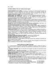
LEXUS IS200.pdf
LEXUS IS200.pdf
LEXUS IS200.pdf

Create successful ePaper yourself
Turn your PDF publications into a flip-book with our unique Google optimized e-Paper software.
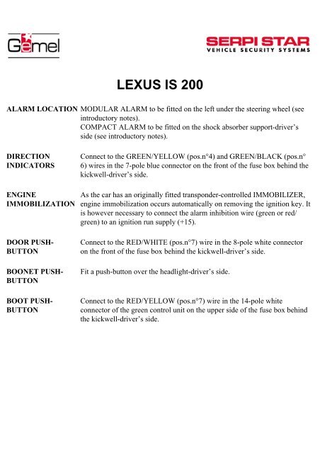
<strong>LEXUS</strong> IS 200<br />
ALARM LOCATION MODULAR ALARM to be fitted on the left under the steering wheel (see<br />
introductory notes).<br />
COMPACT ALARM to be fitted on the shock absorber support-driver’s<br />
side (see introductory notes).<br />
DIRECTION<br />
INDICATORS<br />
ENGINE<br />
IMMOBILIZATION<br />
DOOR PUSH-<br />
BUTTON<br />
BOONET PUSH-<br />
BUTTON<br />
BOOT PUSH-<br />
BUTTON<br />
Connect to the GREEN/YELLOW (pos.n°4) and GREEN/BLACK (pos.n°<br />
6) wires in the 7-pole blue connector on the front of the fuse box behind the<br />
kickwell-driver’s side.<br />
As the car has an originally fitted transponder-controlled IMMOBILIZER,<br />
engine immobilization occurs automatically on removing the ignition key. It<br />
is however necessary to connect the alarm inhibition wire (green or red/<br />
green) to an ignition run supply (+15).<br />
Connect to the RED/WHITE (pos.n°7) wire in the 8-pole white connector<br />
on the front of the fuse box behind the kickwell-driver’s side.<br />
Fit a push-button over the headlight-driver’s side.<br />
Connect to the RED/YELLOW (pos.n°7) wire in the 14-pole white<br />
connector of the green control unit on the upper side of the fuse box behind<br />
the kickwell-driver’s side.
(originally fitted)<br />
ELECTRIC<br />
WINDOWS<br />
FOR THE CONNECTION FOLLOW THE APPROPRIATE<br />
DIAGRAM (diagram n°32)<br />
Left window lift: cut the RED (pos.n°1 positive hen rising) and GREEN<br />
(pos.n°20) wires in the 20-pole white connector of the push-button panel in<br />
the door-driver’s side.<br />
Right window lift: connect to the YELLOW/BLACK (+) pos.n°17 wire in<br />
the 20-pole white connector of the green control unit on the upper side of<br />
the fuse box behind the kickwell-driver’s side.<br />
Rear left window lift: connect to the RED (+) pos. 9 wire in the 14-pole<br />
white connector of the green control unit on the upper side of the fuse box<br />
behind the kickwell-driver’s side.<br />
Rear right window lift: connect to the RED/WHITE (+) pos3 wire in the 20-<br />
pole white connector of the green control unit on the upper side of the fuse<br />
box behind the kickwell-driver’s side.<br />
Connection to a radio-controlled alarm<br />
(originally fitted)<br />
CENTRAL<br />
LOCKING<br />
FOR THE CONNECTION FOLLOW THE APPROPRIATE<br />
DIAGRAM (diagram n°33)<br />
Negative controls.<br />
Connections to be done inside the door-driver’s side.<br />
Connection to an alarm which can be armed by the car’s original transmitter<br />
ARMED ALARM<br />
Yellow/Blue 10A<br />
Green/Blue 5A<br />
White/Blue 4A<br />
Yellow/Red 3A<br />
Follow the enclosed diagram<br />
Connect to the GREEN/YELLOW (pos.n°9) wire in the 12-pole white<br />
connector on the front of the fuse box behind the kickwell-driver’s side.<br />
Connect to the RED/WHITE (pos.n°3) wire in the 12-pole white connector<br />
on the front of the fuse box behind the kickwell-driver’s side.<br />
DO NOT CONNECT<br />
DO NOT CONNECT<br />
The above-mentioned information is given as an indication only and is in no way binding.
Diagram 32
<strong>LEXUS</strong> IS200
Diagrams 33<br />
CENTRAL LOCKING CONNECTION DIAGRAMS TO A ALARM RADIO<br />
CONTROLLED ON <strong>LEXUS</strong> IS200<br />
For alarms with a 5-wires locking circuit<br />
For alarms with a 6-wires locking circuit
<strong>LEXUS</strong> IS 200 (Diag.33a)
<strong>LEXUS</strong> IS 200 (Diag.33b)