Digital dimmable ballasts for fluorescent lamps EXCEL ... - Tridonic
Digital dimmable ballasts for fluorescent lamps EXCEL ... - Tridonic
Digital dimmable ballasts for fluorescent lamps EXCEL ... - Tridonic

You also want an ePaper? Increase the reach of your titles
YUMPU automatically turns print PDFs into web optimized ePapers that Google loves.
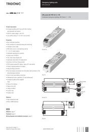
FL <strong>ballasts</strong><br />
Electronic dimming<br />
T8<br />
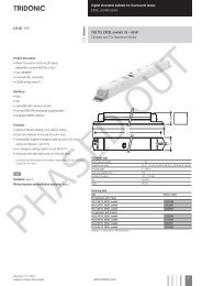
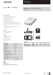
PCA T8 <strong>EXCEL</strong> one4all lp Y, 3x18 W and 4x18 W<br />
<strong>EXCEL</strong> T8<br />
Product description<br />
• Processor-controlled ballast with y inside<br />
• Highest possible energy class CELMA EEI = A1 BAT 1<br />
• Noise-free precise control via DALI or<br />
DSI signal, switchDIM or corridorFUNCTION<br />
• OEM-specific reserved memory areas<br />
• Extended DALI commands<br />
• 5-year guarantee<br />
Interfaces<br />
• DALI<br />
• DSI<br />
• switchDIM (with memory function + selectable dimming rate)<br />
• corridorFUNCTION (individually programmable)<br />
Functions<br />
• Intelligent Temperature Guard (overtemperature protection)<br />
• Intelligent Voltage Guard (overvoltage indication<br />
and undervoltage shutdown)<br />
• Optimum filament heating in any dimmer setting<br />
• Disconnection of filament heating from a dimming level of approx.<br />
90 % <strong>for</strong> maximum energy efficiency (SMART-Heating concept)<br />
• Fade rates between 50 ms and 90 s (min. – max.)<br />
• Automatically triggered emergency lighting value in DC mode,<br />
can be set between 1 and 100 %<br />
• For emergency lighting systems as per EN 50172<br />
• Automatic start after replacement of defective <strong>lamps</strong><br />
• Automatic shutdown if the lamp is faulty<br />
• Dimming possible in DC mode<br />
3,5<br />
4,1<br />
6<br />
Technical data<br />
Mains voltage range<br />
220 – 240 V<br />
AC voltage range<br />
198 – 264 V<br />
DC voltage range<br />
176 – 280 V (lamp start ≥ 198 V DC)<br />
Mains frequency<br />
0 / 50 / 60 Hz<br />
Overvoltage protection<br />
320 V AC, 1 h<br />
Typ. power input on standby<br />
< 0.5 W<br />
Protective hot restart<br />
0.5 s <strong>for</strong> AC / 0.2 s <strong>for</strong> DC<br />
Dimming range, 3 <strong>lamps</strong> 5 – 100 %<br />
Dimming range, 4 <strong>lamps</strong> 1 – 100 %<br />
Lamp start possible from<br />
5 % (3 <strong>lamps</strong>), 1 % (4 <strong>lamps</strong>)<br />
Operating frequency<br />
~ 40 – 100 kHz<br />
Type of protection<br />
IP20<br />
L<br />
D<br />
21<br />
4,1<br />
40<br />
È<br />
Standards, page 2<br />
Wiring diagrams and installation examples, page 5<br />
Ordering data<br />
Type<br />
Article number<br />
Packaging,<br />
carton<br />
Packaging,<br />
pallet<br />
Weight<br />
per pcs.<br />
For luminaires with 3 <strong>lamps</strong><br />
PCA 3x18 T8 <strong>EXCEL</strong> one4all lp Y 22185247 20 pc./pcs. 600 pc./pcs. 0.303 kg<br />
For luminaires with 4 <strong>lamps</strong><br />
PCA 4x18 T8 <strong>EXCEL</strong> one4all lp Y 22185250 20 pc./pcs. 600 pc./pcs. 0.338 kg<br />
Specific technical data<br />
Lamp<br />
wattage<br />
Lamp<br />
type<br />
Type<br />
For luminaires with 3 <strong>lamps</strong><br />
Article<br />
number<br />
Dimensions<br />
L x W x H<br />
Hole spacing<br />
D<br />
Lamp<br />
power2<br />
Circuit<br />
power2<br />
EEI<br />
Current at<br />
50 Hz 230 V2<br />
λ at<br />
50 Hz 230 V<br />
tc point<br />
max.<br />
Ambient<br />
temperature ta3<br />
3 x 18 W T8 PCA 3x18 T8 <strong>EXCEL</strong> one4all lp Y 22185247 360 x 40 x 21 mm 350 mm 48.5 W 51 W A1 BAT 0.23 A 0.97 75 °C -25 ... 60 °C<br />
For luminaires with 4 <strong>lamps</strong><br />
4 x 18 W T8 PCA 4x18 T8 <strong>EXCEL</strong> one4all lp Y 22185250 360 x 40 x 21 mm 350 mm 65.0 W 69 W A1 BAT 0.31 A 0.98 80 °C -25 ... 60 °C<br />
1 According to the EU directives on ecodesign requirements (EC) No. 245/2009 and (EC) No. 347/2010.<br />
2 Valid at 100 % dimming level.<br />
3 +10 °C to ta max: unrestricted dimming. -25 °C to +10 °C: unrestricted dimming from 100 % to 30 %.<br />
-25 °C to +10 °C, dimming below 30 %: malfunction possible but no damage to ECG. This applies to AC and DC operation.<br />
Data sheet 02/13-FD015-2<br />
Subject to change without notice.<br />
www.tridonic.com 1
FL <strong>ballasts</strong><br />
Electronic dimming<br />
Standards<br />
EN 55015<br />
EN 60929<br />
EN 61000-3-2<br />
EN 61347-2-3<br />
EN 61547<br />
Suitable <strong>for</strong> emergency installations according to<br />
EN 50172<br />
Lamp starting characteristics<br />
Warm start<br />
Starting time 0.5 s with AC<br />
Starting time 0.2 s with DC<br />
Start at any dimming level<br />
AC operation<br />
Mains voltage<br />
220–240 V 50/60 Hz<br />
198–264 V 50/60 Hz including safety<br />
tolerance (±10 %)<br />
202–254 V 50/60 Hz including per<strong>for</strong>mance<br />
tolerance (+6 % / -8 %)<br />
Mains currents in DC operation (at 70 % light output)<br />
Wattage Mains current at<br />
Mains current at<br />
Type<br />
Un = 220 VDC<br />
Un = 275 VDC<br />
PCA 3x18 T8 <strong>EXCEL</strong> one4all lp Y 3x18 W 0.22 A 0.17 A<br />
PCA 4x18 T8 <strong>EXCEL</strong> one4all lp Y 4x18 W 0.28 A 0.22 A<br />
Ballast lumen factor AC operation (AC-BLF) EN 60929 8.1<br />
Wattage<br />
AC-BLF at<br />
Type<br />
U = 230 VAC<br />
PCA 3x18 T8 <strong>EXCEL</strong> one4all lp Y 3x18 W 0.98<br />
PCA 4x18 T8 <strong>EXCEL</strong> one4all lp Y 4x18 W 0.99<br />
The ballast lumen factor <strong>for</strong> AC operation (AC-BLF) does not alter from Un = 198 V AC to Un = 254 V AC.<br />
The ballast lumen factor <strong>for</strong> DC operation (DC-BLF) on the basis of an automatic power reduction of the <strong>ballasts</strong><br />
(default value is 70 %) will be smaller than AC. It does not alter in the DC operating range (198–280 V DC).<br />
Harmonic distortion in the mains supply (at 230 V / 50 Hz)<br />
Type Wattage THD 3 5 7 9 11<br />
PCA 3x18 T8 <strong>EXCEL</strong> one4all lp Y 3x18 W 7 4 2 2 1 1<br />
PCA 4x18 T8 <strong>EXCEL</strong> one4all lp Y 4x18 W 7 4 2 1 1 1<br />
DC operation<br />
220–240 V 0 Hz<br />
198–280 V 0 Hz certain lamp start<br />
176–280 V 0 Hz operating range<br />
Use in emergency lighting installations according to<br />
EN 50172 or <strong>for</strong> emergency luminaires according<br />
to EN 61347-2-3 appendix J.<br />
Emergency units<br />
The “PCA T8 <strong>EXCEL</strong> lp y” <strong>ballasts</strong> are compatible<br />
with all emergency units from <strong>Tridonic</strong>. See the table in<br />
the data sheet. Also all “5-pole” emergency units can<br />
be used. When used with other emergency units tests<br />
are necessary.<br />
Temperature range<br />
Unlimited dimming range from 10 °C to ta max.<br />
-25 °C to +10 °C: dimming operation from 100 %<br />
to 30 %. If dimm level goes below 30 % malfunction<br />
possible, but no electronic ballast damage.<br />
This applies to AC and DC operation.<br />
Data sheet 02/13-FD015-2<br />
Subject to change without notice.<br />
www.tridonic.com 2
FL <strong>ballasts</strong><br />
Electronic dimming<br />
Dimming<br />
Dimming curve is adapted to the eye sensitiveness.<br />
Dimming range:<br />
4-lamp: 1 % to 100 %, 3-lamp: 5 % to 100 %<br />
<strong>Digital</strong> control with:<br />
• DSI signal: 8 bit Manchester Code<br />
Speed 1 % to 100 % in 1.4 s<br />
• DALI signal: 16 bit Manchester Code<br />
Maximum speed 1 % to 100 % in 550 ms<br />
(adjustable between 50 ms and 90 s)<br />
Programmable parameter:<br />
Minimum dimming level<br />
Maximum dimming level<br />
Defaults 3-lamp minimum = 5 %<br />
maximum = 100 %<br />
Defaults 4-lamp minimum = 1 %<br />
maximum = 100 %<br />
Control input (DA/D1, DA/D2)<br />
<strong>Digital</strong> DALI signal or a push-to-make switch<br />
(switchDIM) can be wired on the same terminals<br />
(DA and DA).<br />
<strong>Digital</strong> signal DALI/DSI<br />
The control input is non-polar and protected against<br />
accidental connection with a mains voltage up to<br />
264 V. The control signal is not SELV. Control cable has<br />
to be installed in accordance to the requirements of<br />
low voltage installations.<br />
Different functions depending on each module.<br />
SMART interface<br />
An additional interface <strong>for</strong> the direct connection of<br />
the SMART-LS II lp 1) light sensor. The sensor registers<br />
actual ambient light and maintains the individually<br />
defined lux level.<br />
After every mains reset the SMART interface automatically<br />
checks <strong>for</strong> an installed sensor. With the<br />
sensor installed the PCA T8 <strong>EXCEL</strong> one4all lp y<br />
automatically runs in the constant lux level mode.<br />
ON/OFF switch via mains, switchDIM or DALI/DSI<br />
signal.<br />
DALI/DSI signal = 0 switches off,<br />
DALI/DSI signal ≥ 1 switches on.<br />
With relative DALI dimming commands (e.g. up, down<br />
etc.) or switchDIM signals it is possible to change the<br />
controlled light level temporarily.<br />
Temporarily means that after a switching cycle OFF/<br />
ON command the ballast will start at the preset value<br />
determined by the SMART-LS II lp. The installation of<br />
the two wire bus is according to the appropriate low<br />
voltage regulations.<br />
switchDIM<br />
Integrated switchDIM function allows a direct<br />
connection of a push to make switch <strong>for</strong> dimming<br />
and switching.<br />
1)<br />
SMART-LS II lp: article number 86458258<br />
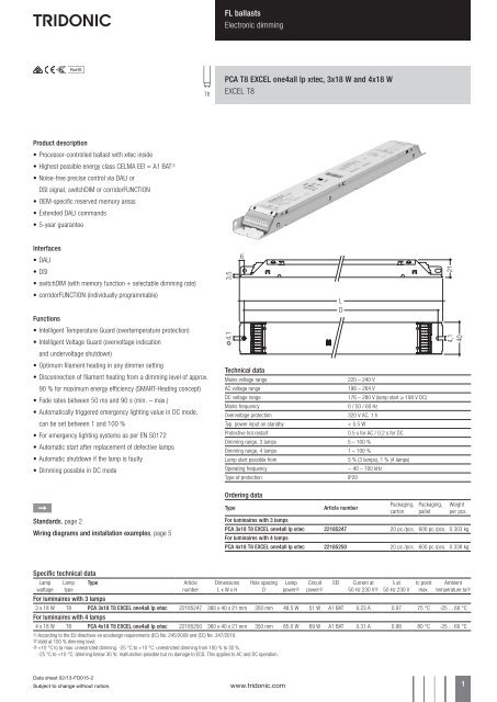
Dimming characteristics<br />
PCA T8 <strong>EXCEL</strong> one4all lp Y<br />
digital dimming value<br />
255<br />
225<br />
200<br />
DALI<br />
175<br />
DSI<br />
150<br />
125<br />
100<br />
75<br />
50<br />
25<br />
0<br />
0 10 20 30 40 50 60 70 80 90 100<br />
relative lighting level in %<br />
Dimming characteristics as seen by the human eye<br />
Brief push (< 0.6 s) switches ballast ON and OFF. The<br />
<strong>ballasts</strong> switch-ON at light level set at switch-OFF.<br />
When the push to make switch is held, PCA <strong>ballasts</strong><br />
are dimmed. After repush the PCA is dimmed in the<br />
opposite direction.<br />
The switchDIM fade time is set to 3 s from min. to<br />
max. in the factory settings. With a 20 s push to the<br />
push to make switch this fade time can be changed<br />
to 6 s. In this instance the switchDIM application will<br />
be synchronized to 50 % light level after 10 s and after<br />
20 s the light level rises to 100 % with the new fade<br />
time.<br />
At every synchronizsation (10 s keystroke) the device<br />
will reset to 3 s (factory setting)<br />
In installations with PCAs with different dimming levels<br />
or opposite dimming directions (e.g. after a system<br />
extension), all PCAs can be synchronized to 50 %<br />
dimming level by a 10 s push.<br />
Use of push to make switch with indicator lamp is not<br />
permitted.<br />
Deactivation: If the corridorFUNCTION is wrongly<br />
activated in a switchDIM system (<strong>for</strong> example a<br />
switch is used instead of pushbutton), there is the<br />
option of installing a pushbutton and deactivating the<br />
corridorFUNCTION mode by five short pushes of the<br />
button within three seconds.<br />
switchDIM and corridorFUNCTION are very simple tools<br />
<strong>for</strong> controlling <strong>ballasts</strong> with conventional momentaryaction<br />
switches or motion sensors.<br />
To ensure correct operation a sinusoidal mains voltage<br />
with a frequency of 50 Hz or 60 Hz is required at the<br />
control input.<br />
Special attention must be paid to achieving clear zero<br />
crossings.<br />
Serious mains faults may impair the operation of<br />
switchDIM and corridorFUNCTION.<br />
Energy saving<br />
PCA T8 <strong>EXCEL</strong> one4all lp Y<br />
mains power in %<br />
100<br />
90<br />
80<br />
70<br />
60<br />
50<br />
40<br />
30<br />
20<br />
10<br />
0<br />
100 90 80 70 60 50 40 30 20 15 10 5 4 3 2 1<br />
dimming level in %<br />
switchDIM PCA T8 <strong>EXCEL</strong> one4all lp Y<br />
DSI<br />
N<br />
L<br />
2<br />
3<br />
4<br />
5 DA / D1<br />
6 DA / D2<br />
2<br />
3<br />
4<br />
5<br />
6<br />
DA / D1<br />
DA / D2<br />
DSI PCA T8 <strong>EXCEL</strong> one4all lp Y<br />
DALI<br />
2<br />
3<br />
4<br />
5<br />
6<br />
DA / D1<br />
DA / D2<br />
DALI PCA T8 <strong>EXCEL</strong> one4all lp Y<br />
Dimmable <strong>ballasts</strong> from <strong>Tridonic</strong> have to be earthed.<br />
Loading of automatic circuit breakers<br />
Automatic circuit breaker type C10 C13 C16 C20 B10 B13 B16 B20<br />
Installation Ø 1.5 mm 2 1.5 mm 2 1.5 mm 2 2.5 mm 2 1.5 mm 2 1.5 mm 2 1.5 mm 2 2.5 mm 2<br />
PCA 3x18 T8 <strong>EXCEL</strong> one4all lp X 22 30 42 48 11 15 21 24<br />
PCA 4x18 T8 <strong>EXCEL</strong> one4all lp X 14 20 28 32 7 10 14 16<br />
Continuous operation: to calculate the protective saftey switch see main current, page 1<br />
Data sheet 02/13-FD015-2<br />
Subject to change without notice.<br />
www.tridonic.com 3
FL <strong>ballasts</strong><br />
Electronic dimming<br />
corridorFUNCTION<br />
Activation: To activate the corridorFUNCTION a voltage<br />
of 230 V simply has to be applied <strong>for</strong> five minutes at<br />
D1, D2. The unit will then switch automatically to the<br />
corridorFUNCTION.<br />
Deactivation: If the corridorFUNCTION is wrongly<br />
activated in a switchDIM system (<strong>for</strong> example a<br />
switch is used instead of pushbutton), there is the<br />
option of installing a pushbutton and deactivating the<br />
corridorFUNCTION mode by five short pushes of the<br />
button within three seconds.<br />
Intelligent Temperature Guard<br />
The intelligent temperature guard protects the<br />
PCA T8 <strong>EXCEL</strong> lp y from thermal overheating by<br />
reducing the output power or switching off in case of<br />
operation above the thermal limits of the luminaire or<br />
ballast. Depending on the luminaire design, the ITG<br />
operates at about 5 to 10 °C above Tc temperature.<br />
Intelligent Voltage Guard<br />
Intelligent Voltage Guard is the name of the new<br />
electronic monitor from <strong>Tridonic</strong>. This inno vative<br />
feature of the PCA family of control gear from <strong>Tridonic</strong><br />
immediately shows if the mains voltage rises above or<br />
falls below certain thresholds. Measures can then be<br />
taken quickly to prevent damage to the control gear.<br />
• If the mains voltage rises above approx. 305 V<br />
(voltage depends on the ballast type), the lamp<br />
starts flashing on and off.<br />
• This signal “demands” disconnection of the<br />
power supply to the lighting system.<br />
• The active-current-control of these control gears<br />
is protected against failure caused by the high mains<br />
currents generated as a result of mains undervoltage.<br />
The switch off level depends on lamp wattage<br />
and is typically < 140 V.<br />
Installation instructions<br />
Operating voltage<br />
Wiring type and cross section<br />
The wiring can be solid cable with a cross section of<br />
0.5 to 0.75 mm² <strong>for</strong> push terminal and 0.5 mm² <strong>for</strong><br />
IDC terminal. For the push-wire connection you have<br />
to strip the insulation (8–9 mm).<br />
Type Wattage Uout<br />
PCA 3x18 T8 <strong>EXCEL</strong> one4all lp Y 3x14 W 430 V<br />
PCA 4x18 T8 <strong>EXCEL</strong> one4all lp Y 4x14 W 430 V<br />
wire preparation:<br />
0.5 – 0.75 mm²<br />
8 – 9 mm<br />
Wiring advice<br />
The lead length is dependent on the capacitance of the cable.<br />
Ballast Terminal Maximum capacitance allowed<br />
Type Cold Middle Hot Cold Middle Hot<br />
PCA 3x18 T8 <strong>EXCEL</strong> one4all lp Y 7, 8 9, 10, 14, 12, 13 100 pF 50 pF 100 pF<br />
15, 16, 17<br />
PCA 4x18 T8 <strong>EXCEL</strong> one4all lp Y 14, 15, 16, 17 7, 8, 9, 10 12, 13, 18, 19 200 pF 50 pF 100 pF<br />
Loosen wire through<br />
twisting and pulling<br />
With standard solid wire 0.5/0.75 mm² the capacitance of the lead is 30–80 pF/m.<br />
This value is influenced by the way the wiring is made.<br />
Lamp connection should be made with symmetrical wiring.<br />
3-lamp devices: Hot and cold leads should be separated as much as possible.<br />
4-lamp devices: Middle and hot leads should be separated as much as possible.<br />
Hot leads (9, 10, 15, 16) and cold leads (11, 12, 13, 14) should be separated as much as possible.<br />
When using two or more <strong>dimmable</strong> <strong>ballasts</strong> in one luminaire with separate dimming controls, the lamp leads must<br />
be kept separate.<br />
Distance to plate: 5 – 10 mm<br />
(ideal distance <strong>for</strong> optimal symmetrical light)<br />
Data sheet 02/13-FD015-2<br />
Subject to change without notice.<br />
www.tridonic.com 4
FL <strong>ballasts</strong><br />
Electronic dimming<br />
control<br />
signal<br />
2<br />
3<br />
4<br />
5 DA/D1<br />
6 DA/D2<br />
7<br />
8<br />
9<br />
10<br />
17<br />
16<br />
15<br />
14<br />
13<br />
12<br />
control<br />
signal<br />
2<br />
3<br />
4<br />
5 DA/D1<br />
6 DA/D2<br />
7<br />
8<br />
9<br />
10<br />
19<br />
18<br />
17<br />
16<br />
15<br />
14<br />
13<br />
12<br />
* leads 12, 13: keep wires short, max. 1.0 m<br />
** leads 9, 10, 14, 15, 16, 17: keep wires short, max. 0.5 m<br />
leads 7, 8: max. 2.0 m<br />
PCA T8 <strong>EXCEL</strong> one4all lp Y 3x18 W<br />
* leads 12, 13, 18, 19: keep wires short, max. 1.0 m<br />
** leads 7, 8, 9, 10: keep wires short, max. 0.5 m<br />
leads 14, 15, 16, 17: max. 2.0 m<br />
PCA T8 <strong>EXCEL</strong> one4all lp Y 4x18 W<br />
Dimmable <strong>ballasts</strong> from <strong>Tridonic</strong> have to be earthed.<br />
RFI<br />
• Connection to the <strong>lamps</strong> of the hot leads must<br />
be kept as short as possible<br />
• Mains leads should be kept apart from lamp leads<br />
(ideally 5–10 cm distance)<br />
• Do not run mains leads adjacent to the<br />
electronic ballast<br />
• Twist the lamp leads<br />
• Keep the distance of lamp leads from the<br />
metal work as large as possible<br />
• Mains wiring to be twisted when through wiring<br />
• Keep the mains leads inside the luminaire as short<br />
as possible<br />
General advise<br />
Electronic <strong>ballasts</strong> are virtually noise free.<br />
Magnetic fields generated during the ignition cycle<br />
can cause some background noise but only <strong>for</strong> a<br />
few milliseconds.<br />
Operation on DC voltage<br />
Our <strong>ballasts</strong> are construed to operate DC voltage and<br />
pulsed DC voltage.<br />
To operate <strong>ballasts</strong> with pulsed DC voltage the polarity<br />
is absolute mandatory.<br />
2<br />
3<br />
4<br />
5<br />
6<br />
–<br />
+<br />
DA<br />
DA<br />
Programming<br />
With appropriate software and a USB interface<br />
different functions can be activated and various<br />
parameters can be configured in the new<br />
PCA T8 <strong>EXCEL</strong> one4all lp y. All that is needed<br />
is a DALI-USB and the software.<br />
MASTER CONFIGURATOR<br />
Full version <strong>for</strong> programming all the functions<br />
and parameters.<br />
pcaCONFIGURATOR<br />
For programming the corridorFUNCTION, device<br />
configuration (fade time, ePowerOnLevel, etc.)<br />
DC level, compatibility settings, and startup date<br />
and <strong>for</strong> resetting.<br />
corridorFUNCTION CONFIGURATOR<br />
For activating and deactivating the corridorFUNCTION<br />
and <strong>for</strong> project-specific programming of the<br />
PCA T8 <strong>EXCEL</strong> one4all lp y units.<br />
PE<br />
L<br />
N<br />
N<br />
L<br />
DALI<br />
PS<br />
USB<br />
SCI<br />
N<br />
L’<br />
2<br />
3<br />
4<br />
5<br />
6<br />
2<br />
3<br />
4<br />
5<br />
6<br />
PE<br />
L<br />
N<br />
DA / D1<br />
DA / D2<br />
PE<br />
L<br />
N<br />
DA / D1<br />
DA / D2<br />
Isolation and electric strength testing of<br />
luminaires<br />
Electronic devices can be damaged by high voltage.<br />
This has to be considered during the routine testing of<br />
the luminaires in production.<br />
According to IEC 60598-1 Annex Q (in<strong>for</strong>mative only!)<br />
or ENEC 303-Annex A, each luminaire should be submitted<br />
to an isolation test with 500 V DC <strong>for</strong> 1 second.<br />
This test voltage should be connected between the<br />
interconnected phase and neutral terminals and the<br />
earth terminal.<br />
The isolation resistance must be at least 2 MΩ.<br />
As an alternative, IEC 60598-1 Annex Q describes a<br />
test of the electrical strength with 1500 V AC (or 1.414<br />
x 1500 V DC). To avoid damage to the electronic<br />
devices this test must not be conducted.<br />
For further technical in<strong>for</strong>mation please visit<br />
www.tridonic.com<br />
PC and the<br />
“corridorFUNCTION CONFIGURATOR”<br />
software tool<br />
any number of ECGs<br />
2<br />
3<br />
4<br />
5<br />
6<br />
PE<br />
L<br />
N<br />
DA / D1<br />
DA / D2<br />
Wiring diagram <strong>for</strong> programming<br />
Data sheet 02/13-FD015-2<br />
Subject to change without notice.<br />
www.tridonic.com 5