SINAMICS S150 Drive Converter Cabinet Units 75 kW to 1200 kW ...
SINAMICS S150 Drive Converter Cabinet Units 75 kW to 1200 kW ...
SINAMICS S150 Drive Converter Cabinet Units 75 kW to 1200 kW ...

Create successful ePaper yourself
Turn your PDF publications into a flip-book with our unique Google optimized e-Paper software.
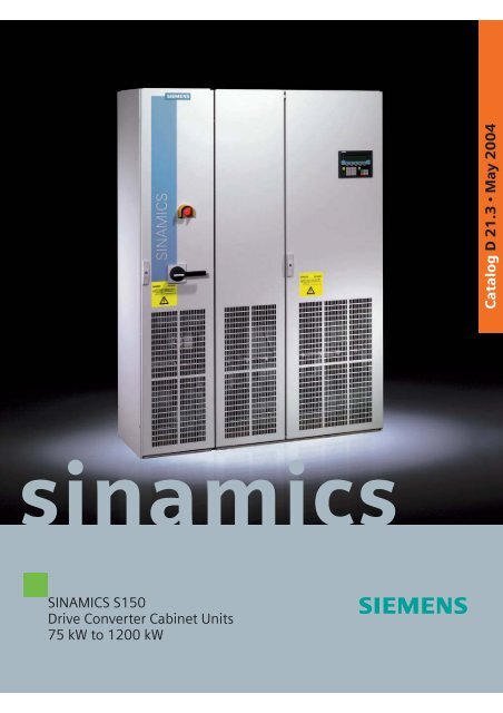
Catalog D 21.3 • May 2004<br />
sinamics<br />
<strong>SINAMICS</strong> <strong>S150</strong><br />
<strong>Drive</strong> <strong>Converter</strong> <strong>Cabinet</strong> <strong>Units</strong><br />
<strong>75</strong> <strong>kW</strong> <strong>to</strong> <strong>1200</strong> <strong>kW</strong>
Related catalogs<br />
<strong>SINAMICS</strong> G130/G150 D 11<br />
<strong>Drive</strong> <strong>Converter</strong> Chassis <strong>Units</strong><br />
<strong>Drive</strong> <strong>Converter</strong> <strong>Cabinet</strong> <strong>Units</strong><br />
Order No.:<br />
German: E86060-K5511-A101-A2<br />
English: E86060-K5511-A101-A2-7600<br />
<strong>SINAMICS</strong> G110 D 11.1<br />
Inverter Chassis <strong>Units</strong><br />
0.12 <strong>kW</strong> <strong>to</strong> 3 <strong>kW</strong><br />
Order No.:<br />
German: E86060-K5511-A111-A1<br />
English: E86060-K5511-A111-A1-7600<br />
<strong>SINAMICS</strong> S120 D 21.2<br />
Servo Control <strong>Drive</strong> System<br />
Order No.:<br />
German: E86060-K5521-A121-A1<br />
English: E86060-K5521-A121-A1-7600<br />
The <strong>SINAMICS</strong> MICROMASTER SIZER<br />
planning <strong>to</strong>ol<br />
The SIZER <strong>to</strong>ol offers fast and simple planning of the<br />
drives<br />
<strong>SINAMICS</strong> G110, <strong>SINAMICS</strong> G130, <strong>SINAMICS</strong> G150,<br />
<strong>SINAMICS</strong> S120, <strong>SINAMICS</strong> <strong>S150</strong> and<br />
MICROMASTER 4.<br />
The <strong>to</strong>ol supports you when planning the technical components<br />
required for a drive task. SIZER leads you<br />
through all planning steps covering the power supply,<br />
drive components and mo<strong>to</strong>rs.<br />
Mo<strong>to</strong>rs are planned using standardized load characteristics,<br />
cyclic drives or free load cycles. The drive components<br />
required (e.g. power sections, power supplies) are<br />
determined by calculation. The planning function completes<br />
the drive system by supplementary components<br />
(e.g. sensor modules, terminal extension, cables, reac<strong>to</strong>rs,<br />
filters).<br />
SIMOVERT MV DA 63<br />
Medium-Voltage <strong>Drive</strong>s<br />
660 kVA <strong>to</strong> 9100 kVA<br />
Order No.:<br />
German: E86060-K5363-A101-A2<br />
English: E86060-K5363-A101-A2-7600<br />
SIMOVERT DA 65.10<br />
MASTERDRIVES VC<br />
0.55 <strong>kW</strong> <strong>to</strong> 2300 <strong>kW</strong><br />
Order No.:<br />
German: E86060-K5165-A101-A3<br />
English: E86060-K5165-A101-A3-7600<br />
Low-Voltage Mo<strong>to</strong>rs M 11<br />
Order No.:<br />
German: E86060-K1711-A101-A3<br />
English: E86060-K1711-A101-A3-7600<br />
Components for CA 01<br />
Au<strong>to</strong>mation<br />
Order No.:<br />
German: E86060-D4001-A100-C1<br />
English: E86060-D4001-A100-C2-7600<br />
A&D Mall<br />
Internet:<br />
http://www.siemens.com/au<strong>to</strong>mation/mall<br />
Trademarks<br />
All designations marked in this Catalog with ® are<br />
registered trademarks of Siemens AG.<br />
Other designations used in this document may be<br />
trademarks; the owner's rights may be violated if they<br />
are used by third parties for their own purposes.<br />
The guided planning helps beginners when using the <strong>to</strong>ol.<br />
Status information always shows you the planning<br />
progress. The online help supports you during planning.<br />
In addition <strong>to</strong> the calculated data, characteristics are displayed<br />
<strong>to</strong> assist you with optimization and <strong>to</strong> display the<br />
reserves.<br />
Using the export function, the parts list can be sent <strong>to</strong> the<br />
SAP-VSR ordering system.<br />
Minimum hardware and software requirements<br />
PG or PC with PentiumTM II 400 MHz (NT, 2000),<br />
PentiumTM III 500 MHz (XP) 256 MB RAM<br />
At least 600 MB vacant hard disk memory<br />
Plus 100 MB vacant hard disk memory on Windows system<br />
drive<br />
Moni<strong>to</strong>r resolution 1024x768 pixels<br />
WindowsTM NT 4.0 SP5, 2000 SP2, XP SP1<br />
Microsoft Internet Explorer 5.5 SP2<br />
Use<br />
Use of <strong>SINAMICS</strong> MICROMASTER SIZER is free of<br />
charge. A nominal fee is charged for handling the order.<br />
The HMI is designed in German/English.<br />
The <strong>SINAMICS</strong> MICROMASTER SIZER planning <strong>to</strong>ol can<br />
be obtained using<br />
Order No. 6SL3070-0AA00-0AG0<br />
from your local Siemens office or representative.
<strong>SINAMICS</strong> <strong>S150</strong><br />
<strong>Drive</strong> <strong>Converter</strong><br />
<strong>Cabinet</strong> <strong>Units</strong><br />
Catalog D 21.3<br />
May 2004<br />
© Siemens AG 2004<br />
Introduction<br />
<strong>SINAMICS</strong> <strong>S150</strong><br />
Dimension drawings<br />
Welcome <strong>to</strong> Au<strong>to</strong>mation<br />
and <strong>Drive</strong>s<br />
Totally Integrated<br />
Au<strong>to</strong>mation<br />
<strong>SINAMICS</strong><br />
1<br />
Overview<br />
Benefits<br />
Application<br />
Design<br />
Function<br />
Technical data<br />
Selection and Ordering<br />
data<br />
Accessories<br />
Options<br />
Dimensions<br />
Mechanical connection<br />
data<br />
2<br />
3<br />
The products and systems<br />
described in this<br />
catalog are manufactured<br />
under application of<br />
a quality management<br />
system certified by DQS<br />
in accordance with<br />
DIN EN ISO 9001.<br />
The certificate is recognized<br />
by all IQ Net<br />
countries.<br />
Engineering<br />
information<br />
Services and<br />
documentation<br />
Cus<strong>to</strong>mer’s terminal block<br />
Dimensioning and<br />
selection information<br />
Information on drive<br />
dimensioning<br />
Mo<strong>to</strong>rs 4<br />
Training<br />
Service & Support<br />
Documentation<br />
5<br />
s<br />
Appendix<br />
Siemens contacts worldwide<br />
A&D online services<br />
Terms and Conditions of<br />
sale and delivery<br />
Export regulations 6
Welcome <strong>to</strong><br />
Au<strong>to</strong>mation and <strong>Drive</strong>s<br />
We would like <strong>to</strong> welcome you <strong>to</strong> Au<strong>to</strong>mation and<br />
<strong>Drive</strong>s and our comprehensive range of products,<br />
systems, solutions and services for production and<br />
process au<strong>to</strong>mation and building technology<br />
worldwide.<br />
With Totally Integrated Au<strong>to</strong>mation and Totally<br />
Integrated Power, we deliver solution platforms based<br />
on standards that offer you a considerable savings<br />
potential.<br />
Discover the world of our technology now. If you need<br />
more detailed information, please contact one of your<br />
regional Siemens partners.<br />
They will be glad <strong>to</strong> assist you.<br />
1/2 Siemens D 21.3 · May 2004
Siemens D 21.3 · May 2004<br />
1/3
Ethernet<br />
Totally Integrated Au<strong>to</strong>mation –<br />
innovations for more productivity<br />
With the launch of Totally Integrated Au<strong>to</strong>mation, we were<br />
the first ones on the market <strong>to</strong> consistently implement the<br />
trend from equipment <strong>to</strong> an integrated au<strong>to</strong>mation solution,<br />
and have continuously improved the system ever since.<br />
Whether your industry is process- and production-oriented or<br />
a hybrid, Totally Integrated Au<strong>to</strong>mation is a unique "common<br />
solution" platform that covers all the sec<strong>to</strong>rs.<br />
Totally Integrated Au<strong>to</strong>mation is an integrated platform for the<br />
entire production line - from receiving <strong>to</strong> technical processing<br />
ERP<br />
Enterprise<br />
Resource<br />
Planning<br />
Ethernet<br />
MES<br />
Manufacturing<br />
Execution<br />
Systems<br />
Ethernet<br />
Production<br />
Order<br />
Management<br />
Production<br />
Operations<br />
Recording<br />
Material<br />
Management<br />
Equipment<br />
Management<br />
Control<br />
SIMATIC NET<br />
Industrial<br />
Communication<br />
SINAUT Telecontrol<br />
System<br />
SIMATIC<br />
Software<br />
SIMATIC<br />
Machine Vision<br />
Industrial<br />
Industrial<br />
Ethernet<br />
Safety Integrated<br />
Industrial Wireless<br />
Communication/<br />
MOBIC<br />
PROCESS FIELD<br />
PROFIBUS<br />
PC-based Au<strong>to</strong>mation<br />
AS-Interface<br />
GAMMA instabus<br />
Building<br />
Technology<br />
Micro-Au<strong>to</strong>mation<br />
and<br />
Actua<strong>to</strong>r-Sensor<br />
Interface Level<br />
ECOFAST IP65<br />
Decentral<br />
Au<strong>to</strong>mation System<br />
1/4<br />
Siemens D 21.3 · May 2004
and production areas <strong>to</strong> shipping. Thanks <strong>to</strong> the system-oriented<br />
engineering environment, integrated, open communications<br />
as well as intelligent diagnostics options, your plant now<br />
benefits in every phase of the life cycle.<br />
In fact, <strong>to</strong> this day we are the only company worldwide that<br />
can offer a control system based on an integrated platform<br />
for both the production and process industry.<br />
SIMATIC IT Framework<br />
Production Modeler<br />
Plant<br />
Information<br />
Management<br />
Detailed<br />
Production<br />
Scheduling<br />
Product Specification<br />
Management System<br />
Labora<strong>to</strong>ry Information<br />
Management System<br />
SIMATIC<br />
Controller/<br />
Au<strong>to</strong>mation<br />
System<br />
SINUMERIK<br />
Numeric<br />
Control<br />
SIMOTION<br />
Motion Control<br />
System<br />
SIMATIC HMI<br />
Human Machine<br />
Interface<br />
SENTRON<br />
Circuit<br />
Breakers<br />
SIMATIC<br />
Distributed<br />
I/O<br />
SIMATIC PCS 7<br />
Process Control<br />
System<br />
Field Instrumentation/<br />
Analytics<br />
SIMOCODE-DP<br />
Mo<strong>to</strong>r<br />
Protection<br />
and Control<br />
Sensor<br />
Technology<br />
IQ-Sense<br />
HART<br />
PROFIBUS PA<br />
SIMODRIVE<br />
<strong>SINAMICS</strong><br />
<strong>Drive</strong> Systems/<br />
<strong>SINAMICS</strong><br />
Siemens D 21.3 · May 2004<br />
1/5
Introduction<br />
1<br />
<strong>SINAMICS</strong> range of converters<br />
<strong>SINAMICS</strong> G<br />
<strong>SINAMICS</strong> S<br />
Extrusion<br />
Forming/Shaping<br />
Pumps/Fans<br />
Packaging<br />
Printing Machines<br />
Textiles<br />
Conveyor Systems<br />
Rolling Mills<br />
Machine Tools<br />
G_D212_EN_00053<br />
<strong>SINAMICS</strong> applications<br />
Applications<br />
<strong>SINAMICS</strong> is the new range of Siemens converters designed for<br />
machine and plant engineering applications. <strong>SINAMICS</strong> offers<br />
solutions for all drive tasks:<br />
7 Simple pump and fan applications in the process industry<br />
7 Complex individual drives in centrifuges, presses, extruders,<br />
eleva<strong>to</strong>rs, as well as conveyor and transport systems<br />
7 <strong>Drive</strong> line-ups in textile, plastic film, and paper machines, as<br />
well as in rolling mill plants<br />
7 Highly dynamic servo drives for machine <strong>to</strong>ols, as well as<br />
packaging and printing machines.<br />
Versions<br />
Depending on the application, the <strong>SINAMICS</strong> range offers the<br />
ideal version for any drive task.<br />
7 <strong>SINAMICS</strong> G is designed for standard applications with asynchronous<br />
mo<strong>to</strong>rs. These applications have less stringent requirements<br />
regarding the dynamics and accuracy of the mo<strong>to</strong>r<br />
speed.<br />
7 <strong>SINAMICS</strong> S handles complex drive tasks with synchronous/asynchronous<br />
mo<strong>to</strong>rs and fulfills stringent requirements<br />
regarding:<br />
- Dynamics and accuracy<br />
- Integration of extensive technological functions in the drive<br />
control system.<br />
Platform Concept and Totally Integrated Au<strong>to</strong>mation<br />
All <strong>SINAMICS</strong> versions are based on a platform concept. Joint<br />
hardware and software components, as well as standardized<br />
<strong>to</strong>ols for design, configuration, and commissioning tasks ensure<br />
high-level integration across all components. <strong>SINAMICS</strong> handles<br />
a wide variety of drive tasks with no system gaps. The different<br />
<strong>SINAMICS</strong> versions can be easily combined with each<br />
other.<br />
<strong>SINAMICS</strong> is a part of Siemens “Totally Integrated Au<strong>to</strong>mation”.<br />
Integrated <strong>SINAMICS</strong> systems covering configuration, data<br />
s<strong>to</strong>rage, and communication at au<strong>to</strong>mation level, ensure lowmaintenance<br />
solutions with SIMATIC ® and SIMOTION ® .<br />
1/6 Siemens D 21.3 · May 2004
Introduction<br />
<strong>SINAMICS</strong> range of converters<br />
1<br />
<strong>SINAMICS</strong> as part of the Siemens modular au<strong>to</strong>mation concept<br />
Quality <strong>to</strong> DIN EN ISO 9001<br />
<strong>SINAMICS</strong> conforms with the most exacting quality requirements.<br />
Comprehensive quality assurance measures at the product<br />
design stage, as well as in all development and production<br />
processes, ensure a consistently high level of quality.<br />
Of course, our quality assurance system is certified by an independent<br />
authority <strong>to</strong> DIN EN ISO 9001.<br />
Siemens D 21.3 · May 2004<br />
1/7
Introduction<br />
1<br />
<strong>SINAMICS</strong> range of converters<br />
The <strong>SINAMICS</strong> family comprises three members tailored <strong>to</strong> the<br />
respective application fields:<br />
7 <strong>SINAMICS</strong> G110 – the versatile drive in the lower power range<br />
7 <strong>SINAMICS</strong> G130 and <strong>SINAMICS</strong> G150 – the universal drive<br />
solution for single drives with high output rating<br />
7 <strong>SINAMICS</strong> S120 – the universal, modular drive system for<br />
demanding tasks<br />
7 <strong>SINAMICS</strong> <strong>S150</strong> – the sophisticated drive solution for single<br />
drives with high output rating.<br />
<strong>SINAMICS</strong> ...<br />
<strong>SINAMICS</strong> is characterized by the following system features:<br />
• Uniform functionality based on a common platform strategy<br />
• Uniform engineering<br />
• High degree of flexibility and combination<br />
• Wide output power range<br />
• Designed for worldwide use<br />
• <strong>SINAMICS</strong> Safety Integrated<br />
• Increased economy and effectiveness<br />
• Flexible interfacing facilities <strong>to</strong> host controllers<br />
• Totally Integrated Au<strong>to</strong>mation.<br />
...for every output rating<br />
<strong>SINAMICS</strong><br />
<strong>SINAMICS</strong><br />
<strong>SINAMICS</strong><br />
<strong>SINAMICS</strong><br />
<strong>SINAMICS</strong><br />
G110<br />
0.12 <strong>kW</strong><br />
...for every functionality<br />
S120 G130 G150 / <strong>S150</strong><br />
1 MW<br />
100 MW<br />
G110<br />
G130<br />
G150<br />
S120<br />
<strong>S150</strong><br />
S120<br />
Basic functionality<br />
Motion control functionality<br />
...for every application<br />
G110<br />
General<br />
performance drives<br />
G130<br />
G150<br />
High-performance single drives<br />
<strong>S150</strong><br />
S120<br />
Coordinated drives/<br />
Servo drives<br />
G_D011_EN_00057<br />
1/8 Siemens D 21.3 · May 2004
<strong>SINAMICS</strong> <strong>S150</strong> drive<br />
converter cabinet units<br />
2/2 Overview<br />
2/2 Benefits<br />
2/2 Application<br />
2/3 Design<br />
2/4 Function<br />
2/4 Opera<strong>to</strong>r panel<br />
2/5 Communication with higher-level<br />
control and cus<strong>to</strong>mer’s terminal<br />
block<br />
2/6 Open-loop and closed-loop<br />
control functions<br />
2/6 Software and protection functions<br />
2/7 Technical Data<br />
2/8 Derating data<br />
2/9 Overload capability<br />
2/9 EMC information<br />
2/10 Earthing<br />
2/11 Selection and ordering data<br />
2/12 Accessories<br />
2/13 Options<br />
2/14 Option selection matrix<br />
2/15 Ordering examples<br />
2/16 Description of options<br />
Siemens D 21.3 · May 2004
2<br />
<strong>SINAMICS</strong> <strong>S150</strong><br />
<strong>Drive</strong> converter cabinet units<br />
<strong>75</strong> <strong>kW</strong> <strong>to</strong> <strong>1200</strong> <strong>kW</strong><br />
■ Overview<br />
<strong>SINAMICS</strong> <strong>S150</strong> drive converter cabinet unit (example with options)<br />
■ Benefits<br />
The self-commutating, pulsed rectifier/feedback unit which is<br />
based on IBGT technology and is equipped with a Clean Power<br />
Filter makes the minimum of demands on the line, which is characterized<br />
by the following features:<br />
• The innovative Clean Power Filter minimizes line harmonics<br />
• Power feedback (four-quadrant operation)<br />
• Tolerant <strong>to</strong>wards fluctuations in line voltage<br />
• High line stability (high availability)<br />
• Operation on weak power supplies<br />
• Reactive power compensation is possible<br />
(inductive or capacitive)<br />
• High drive dynamics.<br />
Simple handling of the drive from configuration <strong>to</strong> operation as a<br />
result of:<br />
• Compact and modular, service-friendly design<br />
• Straightforward planning and design<br />
• Ready <strong>to</strong> connect <strong>to</strong> facilitate the installation process<br />
• Fast, menu-prompted commissioning with no complex parameterization<br />
• Clear and convenient operation via a user-friendly graphical<br />
opera<strong>to</strong>r control panel with measured values displayed in<br />
plain text or in a quasi-analog bar display.<br />
<strong>SINAMICS</strong> <strong>S150</strong> drive converter cabinet units are particularly<br />
suitable for all variable-speed drives with high performance requirements,<br />
i.e. drives with:<br />
• High dynamic response requirements<br />
• Frequent braking cycles with high braking energy<br />
• Four-quadrant operation.<br />
<strong>SINAMICS</strong> <strong>S150</strong> provides high-performance speed control with<br />
a high accuracy and dynamic response.<br />
They are available for the following voltages and outputs:<br />
Voltage<br />
Output<br />
380 V <strong>to</strong> 480 V 110 <strong>kW</strong> <strong>to</strong> 800 <strong>kW</strong><br />
660 V <strong>to</strong> 690 V <strong>75</strong> <strong>kW</strong> <strong>to</strong> <strong>1200</strong> <strong>kW</strong><br />
Degrees of protection are IP20 (standard), and as an option<br />
IP21, IP23 and IP54.<br />
The drive converter cabinet units make it possible <strong>to</strong> install line<br />
side and mo<strong>to</strong>r side components as well as additional moni<strong>to</strong>ring<br />
units.<br />
A wide range of electrical and mechanical components enable<br />
the drive system <strong>to</strong> be optimized for the respective requirements.<br />
■ Application<br />
Typical applications for <strong>SINAMICS</strong> <strong>S150</strong> include:<br />
• Test bay drives<br />
• Centrifuges<br />
• Eleva<strong>to</strong>rs and cranes<br />
• Paper and rolling-mill drives<br />
• Cross cutters and shears<br />
• Conveyor belts<br />
• Presses<br />
• Cable winches.<br />
Worldwide application<br />
<strong>SINAMICS</strong> <strong>S150</strong> drive converter cabinet units are manufactured<br />
in compliance with relevant international standards and directives,<br />
and are therefore suitable for worldwide use (see Technical<br />
data).<br />
2/2 Siemens D 21.3 · May 2004
<strong>SINAMICS</strong> <strong>S150</strong><br />
<strong>Drive</strong> converter cabinet units<br />
<strong>75</strong> <strong>kW</strong> <strong>to</strong> <strong>1200</strong> <strong>kW</strong><br />
■ Design<br />
The <strong>SINAMICS</strong> <strong>S150</strong> drive converter cabinet units are characterized<br />
by their compact, modular and service-friendly design.<br />
1<br />
2<br />
Line connection<br />
-X1<br />
PE<br />
2<br />
3<br />
Main control switch 1)<br />
4<br />
Fuses 1)<br />
Main contac<strong>to</strong>r 2)<br />
5<br />
Active interface module<br />
with Clean Power Filter<br />
6<br />
Active line module<br />
AC<br />
7<br />
DC<br />
8<br />
G_D213_EN_00001a<br />
DC link<br />
DC<br />
1<br />
2<br />
3<br />
4<br />
Active interface module with Clean Power Filter and<br />
main contac<strong>to</strong>r<br />
Active line module<br />
Mo<strong>to</strong>r module<br />
Control unit with PROFIBUS connection<br />
Mo<strong>to</strong>r module<br />
Mo<strong>to</strong>r connection<br />
-X2<br />
AC<br />
PE<br />
G_D213_EN_00002a<br />
5<br />
Main control switch with fuses<br />
6<br />
Cus<strong>to</strong>mer's terminal block<br />
7<br />
Line connection (-X1)<br />
8<br />
Mo<strong>to</strong>r connection (-X2)<br />
Option<br />
Standard version<br />
Option<br />
1) Main control switch with fuses only with<br />
output current < 800 A<br />
2) Main contac<strong>to</strong>r with output current < 800 A<br />
or circuit-breaker with output current > 800 A<br />
available as standard<br />
Example of the design of a <strong>SINAMICS</strong> <strong>S150</strong> drive converter cabinet unit<br />
Basic design of a <strong>SINAMICS</strong> <strong>S150</strong> drive converter cabinet unit with a<br />
number of version-specific options<br />
Siemens D 21.3 · May 2004<br />
2/3
2<br />
<strong>SINAMICS</strong> <strong>S150</strong><br />
<strong>Drive</strong> converter cabinet units<br />
<strong>75</strong> <strong>kW</strong> <strong>to</strong> <strong>1200</strong> <strong>kW</strong><br />
■ Function<br />
Opera<strong>to</strong>r panel<br />
An opera<strong>to</strong>r panel is located in the cabinet door of the converter<br />
for operation, moni<strong>to</strong>ring and commissioning tasks. It has the<br />
following features:<br />
• Graphical LCD with backlighting for plain-text display and a<br />
"bar display" of process variables<br />
• LEDs for display the operational status<br />
• Help function describing causes of and remedies for faults<br />
and alarms<br />
• Keypad for operational control of a drive<br />
• Local/remote switchover for selecting the input point (priority<br />
assigned <strong>to</strong> opera<strong>to</strong>r panel or cus<strong>to</strong>mer’s terminal block/<br />
PROFIBUS)<br />
• Numeric keypad for input of setpoint or parameter values<br />
• Function keys for prompted navigation in the menu<br />
• Two-stage safety strategy <strong>to</strong> protect against accidental or unauthorized<br />
changes in settings. Operation of the drive from the<br />
opera<strong>to</strong>r panel can be disabled by a password. The OFF key<br />
is fac<strong>to</strong>ry-set <strong>to</strong> "active" but can also be "deactivated" by the<br />
cus<strong>to</strong>mer. A password can be used <strong>to</strong> prevent the unauthorized<br />
modification of converter parameters.<br />
• IP54 degree of protection (when installed).<br />
The following pictures show examples of plain text displays in<br />
various operating phases.<br />
The first commissioning is carried out using the opera<strong>to</strong>r<br />
panel. Screen forms for<br />
• Supply<br />
• Mo<strong>to</strong>r data<br />
• Encoder data<br />
• Parameter values<br />
are run through in succession.<br />
Entering the data for power supply<br />
G_D213_EN_00031<br />
G_D213_EN_00003<br />
To carry out a quick start-up, only 6 mo<strong>to</strong>r parameters need <strong>to</strong><br />
be read from the mo<strong>to</strong>r rating plate and entered in the screen<br />
form:<br />
• Output<br />
• cos ϕ<br />
• Current<br />
• Voltage<br />
• Frequency<br />
• Speed<br />
The type of mo<strong>to</strong>r cooling must be entered in addition.<br />
Opera<strong>to</strong>r panel<br />
The plain text for the display is s<strong>to</strong>red in two languages, and the<br />
currently desired language can be selected using parameters<br />
(English/German as standard, see options for other languages).<br />
The data and the mo<strong>to</strong>r identification are saved following the input<br />
of the parameters. This is followed by au<strong>to</strong>matic optimization<br />
of the closed-loop control.<br />
G_D213_EN_00004<br />
2/4 Siemens D 21.3 · May 2004
■ Function (continued)<br />
During running, current data are indicated on the display as absolute<br />
values, such as setpoint and actual values, or it is possible<br />
<strong>to</strong> parameterize up <strong>to</strong> three process variables as a quasi-analog<br />
bar display.<br />
4 K E C # ! <br />
I A J " $ # # H F 2 = ? J " 9<br />
K J<br />
1 J<br />
" & # 0 8 K J ! & # ! 8<br />
% " & )<br />
= ? J<br />
" $ # H F <br />
# <br />
Any Alarms which occur are indicated by flashing of the yellow<br />
"ALARM" LED, Faults by a lit red "FAULT" LED. Help text can be<br />
called for every fault and alarm, and provides a short description<br />
of the cause and possible remedial measures.<br />
g_D011_en_00012b<br />
<strong>SINAMICS</strong> <strong>S150</strong><br />
<strong>Drive</strong> converter cabinet units<br />
<strong>75</strong> <strong>kW</strong> <strong>to</strong> <strong>1200</strong> <strong>kW</strong><br />
Communication with higher-level control and TM31 cus<strong>to</strong>mer’s<br />
terminal block<br />
A PROFIBUS interface on the control unit and the terminal block<br />
TM31 are available as cus<strong>to</strong>mer interfaces for control.<br />
This cus<strong>to</strong>mer’s terminal block permits connection <strong>to</strong> the higherlevel<br />
control using analog and digital signals as well as the connection<br />
of additional units.<br />
The cus<strong>to</strong>mer’s terminal block contains:<br />
• 8 digital inputs<br />
• 4 bidirectional digital inputs/outputs<br />
• 2 relay outputs with changeover contact<br />
• 2 analog inputs (differential)<br />
• 2 analog outputs<br />
• 1 temperature sensor input (KTY84-130/PTC)<br />
• Auxiliary voltage output ±10 V for analog setpoint input<br />
• Auxiliary voltage output +24 V for digital inputs.<br />
2<br />
G_D213_EN_00006<br />
G_D213_EN_00005<br />
TM31 cus<strong>to</strong>mer’s terminal block<br />
The "Engineering information" includes detailed information on<br />
the interfaces.<br />
Siemens D 21.3 · May 2004<br />
2/5
<strong>SINAMICS</strong> <strong>S150</strong><br />
<strong>Drive</strong> converter cabinet units<br />
<strong>75</strong> <strong>kW</strong> <strong>to</strong> <strong>1200</strong> <strong>kW</strong><br />
■ Function (continued)<br />
Open-loop control and closed-loop control functions<br />
The converter closed-loop control includes a high-quality sensorless<br />
vec<strong>to</strong>r control with speed and current control, mo<strong>to</strong>r and<br />
converter protection, and it is additionally possible <strong>to</strong> connect a<br />
speed sensor (see also Engineering information).<br />
Software and protection functions<br />
The software functions available as standard are described<br />
below:<br />
2<br />
Software and protection function<br />
Setpoint input<br />
Au<strong>to</strong>matic mo<strong>to</strong>r identification<br />
Ramp-function genera<strong>to</strong>r<br />
Kinetic buffering (KIP)<br />
Flying restart 1 )<br />
I 2 t recording for mo<strong>to</strong>r protection<br />
Evaluation of mo<strong>to</strong>r temperature<br />
Mo<strong>to</strong>r blocking protection<br />
Power section protection<br />
Earth fault moni<strong>to</strong>ring on output side<br />
Electronic short-circuit protection on<br />
output side<br />
Thermal overload protection<br />
Description<br />
The setpoint can be defined internally or externally, internally as a fixed, mo<strong>to</strong>rized potentiometer or jog<br />
setpoint, externally via the PROFIBUS interface or an analog input of the cus<strong>to</strong>mer’s terminal block. The<br />
internal fixed setpoints and the mo<strong>to</strong>rized potentiometer setpoint can be switched over or adjusted using<br />
control commands via all interfaces. It is additionally possible <strong>to</strong> apply additional setpoints, direction of<br />
rotation and speed limiting, reversal of direction of rotation and the parameterization of skip frequency<br />
bands.<br />
Au<strong>to</strong>matic mo<strong>to</strong>r identification permits fast and simple commissioning and optimization of the drive control.<br />
A convenient ramp-function genera<strong>to</strong>r with separately adjustable ramp-up and ramp-down times,<br />
<strong>to</strong>gether with adjustable rounding times in the lower and upper speed ranges, improve the control<br />
response and therefore prevent mechanical overloading of the drive train. The deceleration ramps can be<br />
parameterized separately for emergency s<strong>to</strong>p.<br />
Power supply failures are bridged <strong>to</strong> the extent permitted by the kinetic energy of the drive train. The<br />
speed drops depending on the moment of inertia and the load <strong>to</strong>rque. The current speed is reassumed<br />
when the power supply returns.<br />
The flying restart permits connection of the converter <strong>to</strong> a rotating mo<strong>to</strong>r.<br />
The mo<strong>to</strong>r temperature is calculated in a mo<strong>to</strong>r model s<strong>to</strong>red in the converter software, taking in<strong>to</strong> account<br />
the current speed and load. More exact recording of the temperature, also taking in<strong>to</strong> account the influence<br />
of the ambient temperature, is possible by means of direct temperature recording using KTY84 sensors<br />
in the mo<strong>to</strong>r winding.<br />
Mo<strong>to</strong>r protection by evaluation of a temperature sensor type KTY84 or PTC. When connecting a KTY84<br />
sensor, the limits for alarm or shutdown can be adjusted. When connecting a PTC thermis<strong>to</strong>r, the reaction<br />
following triggering of it (alarm or shutdown) can be defined.<br />
A blocked mo<strong>to</strong>r is recognized and protected against thermal overloading by shutting down.<br />
An earth fault on the output side is recognized by a <strong>to</strong>tal current moni<strong>to</strong>r, and results in shutdown in<br />
earthed-neutral systems.<br />
The short-circuit between mo<strong>to</strong>r and converter (on the converter output terminals, in the mo<strong>to</strong>r cable, in<br />
the terminal box) is detected and switched off.<br />
If the excess temperature threshold is triggered, either a shutdown is carried out or au<strong>to</strong>matic influencing<br />
of the control (possibly pulse frequency or output current) so that a reduction in the thermal load is<br />
achieved. Following elimination of the cause of the fault (e.g. improvement in the ventilation), the original<br />
operating values are au<strong>to</strong>matically reassumed.<br />
1) Fac<strong>to</strong>ry setting: not activated (can be parameterized)<br />
2/6 Siemens D 21.3 · May 2004
<strong>SINAMICS</strong> <strong>S150</strong><br />
<strong>Drive</strong> converter cabinet units<br />
<strong>75</strong> <strong>kW</strong> <strong>to</strong> <strong>1200</strong> <strong>kW</strong><br />
■ Technical data<br />
Electrical data<br />
Supply voltages and output ranges<br />
Types of supplies<br />
Line frequency<br />
Output frequency<br />
3 AC 380 V <strong>to</strong> 480 V, ±10% (-15% < 1 min) 110 <strong>kW</strong> <strong>to</strong> 800 <strong>kW</strong><br />
3 AC 660 V <strong>to</strong> 690 V, ±10% (-15% < 1 min) <strong>75</strong> <strong>kW</strong> <strong>to</strong> <strong>1200</strong> <strong>kW</strong><br />
TN/TT supplies or isolated supplies (IT supplies)<br />
47 Hz <strong>to</strong> 63 Hz<br />
0 Hz <strong>to</strong> 300 Hz<br />
Power fac<strong>to</strong>r Adjustable (fac<strong>to</strong>ry-set <strong>to</strong> cos ϕ =1)<br />
Control method<br />
Vec<strong>to</strong>r control with and without sensor or V/f control<br />
Fixed speeds 15 fixed speeds plus 1 minimum speed, programmable (in the default setting, 3 fixed setpoints plus 1<br />
minimum speed are selectable using terminal block/PROFIBUS)<br />
Skipped speed ranges<br />
4, parameterizable<br />
Setpoint resolution<br />
0.001 rpm digital (14 bit + sign)<br />
12 bit analog<br />
Braking operation<br />
Four-quadrant operation possible as standard<br />
(optionally using braking unit if braking is required in event of power failure)<br />
Mechanical data<br />
Degree of protection<br />
IP20 (higher degrees of protection up <strong>to</strong> IP54 optional)<br />
Protection class Acc. <strong>to</strong> EN 50 178 Part 1<br />
Type of cooling<br />
Forced air cooling<br />
Shock-protection<br />
BGV A2<br />
<strong>Cabinet</strong> system<br />
Rittal TS 8, doors with double-barb lock, three-section base plates for cable entry<br />
Paint<br />
RAL 7035 (indoor requirements)<br />
Compliance with standards<br />
Standards EN 60 146-1, EN 61 800-2, EN 61 800-3, EN 50 178, EN 60 204-1, EN 60 529<br />
CE marking<br />
According <strong>to</strong> EMC directive No. 89/336/EC and low voltage directive No. 73/23/EC<br />
RI suppression<br />
According <strong>to</strong> EMC product standard for variable-speed drives EN 61 800-3, second environment.<br />
First environment on request.<br />
2<br />
Operation S<strong>to</strong>rage Transport<br />
Ambient conditions<br />
Ambient temperature 0°C <strong>to</strong> +40 °C<br />
Up <strong>to</strong> +50 °C: see derating data<br />
-25 °C <strong>to</strong> +55 °C -25 °C <strong>to</strong> +70 °C<br />
above -40 °C: for 24 hours<br />
Relative humidity<br />
(non-condensing)<br />
Installation altitude<br />
Mechanical stability<br />
Vibra<strong>to</strong>ry load<br />
5% <strong>to</strong> 95%<br />
corr. <strong>to</strong> 3K3 <strong>to</strong> IEC 60 721-3-3<br />
Deviations from the defined classes are identified by<br />
underlining.<br />
5% <strong>to</strong> 95%<br />
corr. <strong>to</strong> 1K4 <strong>to</strong> IEC 60 721-3-1<br />
5% <strong>to</strong> 95% at 40 °C<br />
corr. <strong>to</strong> 2K3 <strong>to</strong> IEC 60 721-3-2<br />
Up <strong>to</strong> 2000 m above sea level without reduction in performance, > 2000 m: see derating data<br />
- Deflection 0.0<strong>75</strong> mm at 10 Hz <strong>to</strong> 58 Hz 1.5 mm at 5 Hz <strong>to</strong> 9 Hz 3.5 mm at 5 Hz <strong>to</strong> 9 Hz<br />
- Acceleration 9.8 m/s 2 at > 58 Hz <strong>to</strong> 200 Hz<br />
-<br />
Shock load<br />
- Acceleration 100 m/s 2 at 11 ms<br />
corr. <strong>to</strong> 3M4 <strong>to</strong> IEC 60 721-3-3<br />
5 m/s² at > 9 Hz <strong>to</strong> 200 Hz<br />
corr. <strong>to</strong> 1M2 <strong>to</strong> IEC 60 721-3-1<br />
40 m/s² at 22 ms<br />
corr. <strong>to</strong> 1M2 <strong>to</strong> IEC 60 721-3-1<br />
10 m/s² at > 9 Hz <strong>to</strong> 200 Hz<br />
corr. <strong>to</strong> 2M2 <strong>to</strong> IEC 60 721-3-2<br />
100 m/s² at 11 ms<br />
corr. <strong>to</strong> 2M2 <strong>to</strong> IEC 60 721-3-2<br />
Siemens D 21.3 · May 2004<br />
2/7
<strong>SINAMICS</strong> <strong>S150</strong><br />
<strong>Drive</strong> converter cabinet units<br />
<strong>75</strong> <strong>kW</strong> <strong>to</strong> <strong>1200</strong> <strong>kW</strong><br />
■ Technical data (continued)<br />
Derating data<br />
Compensation of current derating as a function of installation<br />
altitude/ambient temperature<br />
2<br />
If the converters are operated at an installation altitude >2000 m<br />
above sea level, the permissible output currents of the converters<br />
must be reduced according <strong>to</strong> the following tables. The degree<br />
of protection of the converter cabinets must be observed.<br />
The listed derating data already include compensation between<br />
the installation altitude and ambient temperature (temperature of<br />
inlet air for converter cabinet).<br />
Installation<br />
altitude above<br />
sea level<br />
Current derating<br />
at an ambient temperature of<br />
m 20 °C 25 °C 30 °C 35 °C 40 °C 45 °C 50 °C<br />
0-2000 95.0% 87.0%<br />
2001-2500 96.3% 91.4% 83.7%<br />
2501-3000 100% 96.2% 92.5% 87.9% 80.5%<br />
3001-3500 96.7% 92.3% 88.8% 84.3% 77.3%<br />
3501-4000 97.8% 92.7% 88.4% 85.0% 80.8% 74.0%<br />
Current derating depending on ambient temperature (temperature of inlet air) and installation altitude for cabinet units with degree of protection IP20,<br />
IP21 and IP23<br />
Installation<br />
altitude above<br />
sea level<br />
Current derating<br />
at an ambient temperature of<br />
m 20 °C 25 °C 30 °C 35 °C 40 °C 45 °C 50 °C<br />
0-2000 95.0% 87.5% 80.0%<br />
2001-2500 100% 96.3% 91.4% 84.2% 77.0%<br />
2501-3000 96.2% 92.5% 87.9% 81.0% 74.1%<br />
3001-3500 96.7% 92.3% 88.8% 84.3% 77.7% 71.1%<br />
3501-4000 97.8% 92.7% 88.4% 85.0% 80.8% 74.7% 68.0%<br />
Current derating depending on ambient temperature (temperature of inlet air) and installation altitude for cabinet units with degree of protection IP54<br />
Voltage derating as a function of the installation altitude<br />
In addition <strong>to</strong> the current derating, the voltage derating must be considered according <strong>to</strong> the following table with installation altitudes<br />
> 2000 m above sea level<br />
Installation<br />
altitude above<br />
sea level<br />
Voltage derating<br />
for a rated input voltage of<br />
Voltage derating<br />
for a rated input voltage of<br />
m 380 V 400 V 420 V 440 V 460 V 480 V 660 V 690 V<br />
0-2000 100%<br />
2001-2250 96% 96%<br />
2251-2500 98% 94% 98% 94%<br />
2501-2<strong>75</strong>0 100% 98% 94% 90% 95% 90%<br />
2<strong>75</strong>1-3000 95% 91% 88% 92% 88%<br />
3001-3250 97% 93% 89% 85% 89% 85%<br />
3251-3500 98% 93% 89% 85% 82% 85% 82%<br />
3501-3<strong>75</strong>0 95% 91% 87% 83% 79% – –<br />
3<strong>75</strong>1-4000 96% 92% 87% 83% 80% 76% – –<br />
Voltage derating as a function of the installation altitude<br />
2/8 Siemens D 21.3 · May 2004
<strong>SINAMICS</strong> <strong>S150</strong><br />
<strong>Drive</strong> converter cabinet units<br />
<strong>75</strong> <strong>kW</strong> <strong>to</strong> <strong>1200</strong> <strong>kW</strong><br />
■ Technical data (continued)<br />
Overload capability<br />
The <strong>SINAMICS</strong> <strong>S150</strong> drive converter cabinet units are equipped<br />
with an overload reserve <strong>to</strong> deal with breakaway <strong>to</strong>rques, for example.<br />
If larger surge loads occur, this must be taken in<strong>to</strong> account<br />
when configuring. In drives with overload requirements,<br />
the appropriate base load current must therefore be used as a<br />
basis for the required load.<br />
The criterion for overload is that the drive is operated with its<br />
base load current before and after the overload occurs, and a<br />
load duration of 300 s is assumed here.<br />
The base load current I L for a small overload is based on a duty<br />
cycle of 110% for 60 s or 150% for 10 s.<br />
The base load current I H for a high overload is based on a duty<br />
cycle of 150% for 60 s or 160% for 10 s.<br />
<strong>Converter</strong> current<br />
1.1<br />
L<br />
L<br />
60 sec<br />
Short-time current<br />
Rated current (permanent)<br />
Base load current L for small overload<br />
300 sec<br />
The first environment comprises living accommodation or locations<br />
where the drive system is directly connected <strong>to</strong> the public<br />
low-voltage network without an intermediate transformer.<br />
The second environment is unders<strong>to</strong>od <strong>to</strong> be all locations outside<br />
living areas. These are basically industrial areas which are<br />
powered from the medium-voltage network via their own transformers.<br />
Four different categories are defined in EN 61 800-3 Ed.2 depending<br />
on the location and the output of the drive:<br />
Category C1: <strong>Drive</strong> systems for rated voltages less than 1000 V<br />
for unlimited use in the first environment.<br />
Category C2: Stationary drive systems for rated voltages less<br />
than 1000 V for use in the second environment. Use in the first<br />
environment is possible if the drive system is installed and used<br />
by qualified personnel. The warning and installation information<br />
supplied by the manufacturer must be observed.<br />
Category C3: <strong>Drive</strong> systems for rated voltages less than 1000 V<br />
for exclusive use in the second environment.<br />
Category C4: <strong>Drive</strong> systems for rated voltages greater than or<br />
equal <strong>to</strong> 1000 V or for rated currents greater than or equal <strong>to</strong><br />
400 A for use in complex systems in the second environment.<br />
The following graphic shows the assignment of the four categories<br />
<strong>to</strong> the first and second environments.<br />
C1<br />
2<br />
G_D213_EN_00007<br />
Small overload<br />
<strong>Converter</strong> current<br />
First<br />
environment<br />
C2<br />
C3<br />
Second<br />
environment<br />
1.5 H<br />
H<br />
High overload<br />
G_D213_EN_00008<br />
60 sec<br />
Short-time current<br />
Rated current (permanent)<br />
Base load current H for high overload<br />
300 sec<br />
EMC information<br />
The electromagnetic compatibility describes - according <strong>to</strong> the<br />
definition of the EMC directive - the "capability of a device <strong>to</strong><br />
work satisfac<strong>to</strong>rily in the electromagnetic environment without itself<br />
causing electromagnetic interferences which are unacceptable<br />
for other devices present in this environment". To guarantee<br />
that the appropriate EMC directives are observed, the devices<br />
must demonstrate a sufficiently high noise immunity, and also<br />
the emitted interference must be limited <strong>to</strong> acceptable values.<br />
The EMC requirements for "Variable-speed drive systems" are<br />
described in the product standard EN 61 800-3. A variablespeed<br />
drive system (or power drive system PDS) consists of the<br />
drive converter and the electric mo<strong>to</strong>r including cables. The<br />
driven machine is not part of the drive system.<br />
EN 61 800-3 defines different limits depending on the location of<br />
the drive system, referred <strong>to</strong> as the first and second environments.<br />
C4<br />
G_D213_EN_00009<br />
<strong>SINAMICS</strong> <strong>S150</strong> is almost exclusively used in the second environment<br />
(categories C3 and C4).<br />
To limit the emitted interference, <strong>SINAMICS</strong> <strong>S150</strong> is equipped<br />
as standard with a line filter according <strong>to</strong> the limits defined in<br />
Category C3. Optional line filters are available on request for use<br />
in the first environment (Category C2).<br />
<strong>SINAMICS</strong> <strong>S150</strong> complies with the noise immunity requirements<br />
defined in EN 61 800-3 for the second environment and<br />
thus also with the lower noise immunity requirements in the first<br />
environment.<br />
The warning and installation information (part of the device documentation)<br />
must be observed.<br />
Siemens D 21.3 · May 2004<br />
2/9
<strong>SINAMICS</strong> <strong>S150</strong><br />
<strong>Drive</strong> converter cabinet units<br />
<strong>75</strong> <strong>kW</strong> <strong>to</strong> <strong>1200</strong> <strong>kW</strong><br />
■ Technical data (continued)<br />
2<br />
Earthing<br />
Required PE conduc<strong>to</strong>r cross-sections:<br />
The PE conduc<strong>to</strong>r must be dimensioned taking in<strong>to</strong> account the<br />
following data:<br />
• In the event of an earth fault, no impermissibly high contact<br />
voltages may occur (< AC 50 V or < DC 120 V, EN 50 178<br />
Section 5.3.2.2, IEC 60 364, IEC 60 543) as a result of voltage<br />
drops of the earth fault current on the PE conduc<strong>to</strong>r.<br />
• The earth fault current flowing in the PE conduc<strong>to</strong>r in the event<br />
of an earth fault must not place an impermissible load on the<br />
PE conduc<strong>to</strong>r.<br />
• If it is possible in the event of a fault according <strong>to</strong> EN 50 178<br />
Section 8.3.3.4 that continuous currents can flow via the PE<br />
conduc<strong>to</strong>r, the cross-section of the PE conduc<strong>to</strong>r must be dimensioned<br />
according <strong>to</strong> this continuous current.<br />
The cross-section of the PE conduc<strong>to</strong>r must be selected according<br />
<strong>to</strong> EN 60 204-1, EN 60 439-1, IEC 60 364.<br />
Cross-section of outer<br />
conduc<strong>to</strong>r<br />
Up <strong>to</strong> 16 mm 2<br />
Minimum cross-section of<br />
external PE conduc<strong>to</strong>r<br />
At least cross-section of outer<br />
conduc<strong>to</strong>r<br />
16 mm 2 <strong>to</strong> 35 mm 2 16 mm 2<br />
Above 35 mm 2<br />
At least half the cross-section of<br />
outer conduc<strong>to</strong>r<br />
• Switchgear and mo<strong>to</strong>rs are usually earthed separately with a<br />
local earth electrode. With this constellation, the earth fault<br />
current flows via the parallel earth connections and is divided.<br />
Despite use of cross-sections for the outer conduc<strong>to</strong>rs in line<br />
with the above table, no impermissible contact voltages then<br />
occur with this earthing.<br />
However, based on experience gained with different earthing<br />
constellations, we recommend direct returning of the earth line<br />
from the mo<strong>to</strong>r <strong>to</strong> the converter. For EMC reasons and <strong>to</strong> prevent<br />
shaft currents, symmetrical mo<strong>to</strong>r cables and not fourwire<br />
cables should be used here. The earth connection (PE)<br />
must be routed separately or arranged symmetrically in the<br />
mo<strong>to</strong>r cable. The symmetry of the PE conduc<strong>to</strong>r is achieved<br />
using a conduc<strong>to</strong>r surrounding all phase conduc<strong>to</strong>rs or using<br />
a cable with a symmetrical arrangement of the three phase<br />
conduc<strong>to</strong>rs and three earth conduc<strong>to</strong>rs.<br />
• By means of their closed-loop control, the converters limit the<br />
load current (mo<strong>to</strong>r and earth fault currents) <strong>to</strong> an rms value<br />
corresponding <strong>to</strong> the rated current. Because of this, we recommend<br />
use of an outer conduc<strong>to</strong>r cross-section analogous<br />
<strong>to</strong> the outer conduc<strong>to</strong>r cross-section for earthing the control<br />
cabinet.<br />
2/10 Siemens D 21.3 · May 2004
■ Selection and ordering data<br />
Small overload High overload Power loss Cooling<br />
air<br />
req.<br />
Output<br />
at<br />
400 V<br />
at at<br />
460 V 690 V<br />
(60 Hz)<br />
Rated Rated<br />
input output<br />
current current<br />
1 ) I N<br />
Basic Output <strong>to</strong> I H<br />
load<br />
current<br />
I 2 L )<br />
Basic<br />
load<br />
at<br />
400 V<br />
at<br />
460 V<br />
at<br />
690 V<br />
current (50 Hz) (60 Hz) (50 Hz)<br />
I 3 H )<br />
<strong>SINAMICS</strong> <strong>S150</strong><br />
<strong>Drive</strong> converter cabinet units<br />
Sound pressure<br />
level<br />
L pA<br />
(1 m)<br />
at<br />
50 Hz<br />
L pA<br />
(1 m)<br />
at<br />
60 Hz<br />
<strong>kW</strong> hp <strong>kW</strong> A A A <strong>kW</strong> hp A <strong>kW</strong> <strong>kW</strong> <strong>kW</strong> m 3 /s dB dB Order No.<br />
<strong>75</strong> <strong>kW</strong> <strong>to</strong> <strong>1200</strong> <strong>kW</strong><br />
<strong>Drive</strong> converter cabinet<br />
units<br />
<strong>SINAMICS</strong> <strong>S150</strong><br />
Supply voltage 3 AC 50 Hz 380 V <strong>to</strong> 440 V / 3 AC 60 Hz 460 V <strong>to</strong> 480 V<br />
110 150 - 197 210 205 90 125 178 5.6 6.1 - 0.58 71 73 6SL3710-7LE32-1AA0<br />
132 200 - 242 260 250 110 150 233 6.6 7.3 - 0.70 71 73 6SL3710-7LE32-6AA0<br />
160 250 - 286 310 302 132 200 277 8.5 9.4 - 1.19 72 74 6SL3710-7LE33-1AA0<br />
200 300 - 349 380 370 160 250 340 9.3 10.2 - 1.19 72 74 6SL3710-7LE33-8AA0<br />
250 400 - 447 490 477 200 350 438 11.7 13.0 - 1.19 72 74 6SL3710-7LE35-0AA0<br />
315 500 - 549 605 590 250 400 460 15.9 17.5 - 1.96 77 79 6SL3710-7LE36-1AA0<br />
400 600 - 674 745 725 315 500 570 18.0 20.0 - 1.96 77 79 6SL3710-7LE37-5AA0<br />
450 700 - <strong>75</strong>9 840 820 400 600 700 18.4 20.4 - 1.96 77 79 6SL3710-7LE38-4AA0<br />
560 800 - 888 985 960 450 700 860 24.4 26.8 - 2.6 77 79 6SL3710-7LE41-0AA0<br />
710 900 - 1133 1260 1230 560 800 1127 28.2 31.4 - 2.6 78 80 6SL3710-7LE41-2AA0<br />
800 1000 - 1262 1405 1370 710 900 1257 30.3 33.8 - 2.6 78 80 6SL3710-7LE41-4AA0<br />
2<br />
Supply voltage 3 AC 50 Hz 660 V <strong>to</strong> 690 V<br />
- - <strong>75</strong> 86 85 80 55 - 76 - - 4.5 0.58 71 73 6SL3710-7LH28-5AA0<br />
- - 90 99 100 95 <strong>75</strong> - 89 - - 4.9 0.58 71 73 6SL3710-7LH31-0AA0<br />
- - 110 117 120 115 90 - 107 - - 5.2 0.58 71 73 6SL3710-7LH31-2AA0<br />
- - 132 144 150 142 110 - 134 - - 5.8 0.58 71 73 6SL3710-7LH31-5AA0<br />
- - 160 166 1<strong>75</strong> 170 132 - 157 - - 9.5 1.19 <strong>75</strong> 77 6SL3710-7LH31-8AA0<br />
- - 200 202 215 208 160 - 192 - - 10.4 1.19 <strong>75</strong> 77 6SL3710-7LH32-2AA0<br />
- - 250 242 260 250 200 - 233 - - 11.1 1.19 <strong>75</strong> 77 6SL3710-7LH32-6AA0<br />
- - 315 304 330 320 250 - 280 - - 12.5 1.19 <strong>75</strong> 77 6SL3710-7LH33-3AA0<br />
- - 400 3<strong>75</strong> 410 400 315 - 367 - - 17.7 1.96 77 79 6SL3710-7LH34-1AA0<br />
- - 450 424 465 452 400 - 416 - - 18.9 1.96 77 79 6SL3710-7LH34-7AA0<br />
- - 560 522 5<strong>75</strong> 560 450 - 514 - - 22.4 1.96 77 79 6SL3710-7LH35-8AA0<br />
- - 710 665 735 710 630 - 657 - - 28.3 2.6 77 79 6SL3710-7LH37-4AA0<br />
- - 800 732 810 790 710 - 724 - - 31.6 2.6 77 79 6SL3710-7LH38-1AA0<br />
- - 900 821 910 880 800 - 814 - - 32.5 2.6 77 79 6SL3710-7LH38-8AA0<br />
- - 1000 923 1025 1000 900 - 917 - - 35.6 2.6 77 79 6SL3710-7LH41-0AA0<br />
- - <strong>1200</strong> 1142 1270 1230 1000 - 1136 - - 40.1 2.6 77 79 6SL3710-7LH41-3AA0<br />
1) The currents listed here are based on a line power fac<strong>to</strong>r of cos ϕ =1.<br />
These currents include 10 A for the external auxiliaries as required for<br />
options L19 and B03, for example.<br />
2) The basic load current I L is based on a duty cycle of 110% for 60 s or<br />
150% for 10 s with a duration of 300 s (see → Technical data → overload<br />
capability).<br />
3) The basic load current I H is based on a duty cycle of 150% for 60 s or<br />
160% for 10 s with a duration of 300 s (see → Technical data → overload<br />
capability).<br />
Siemens D 21.3 · May 2004<br />
2/11
<strong>SINAMICS</strong> <strong>S150</strong><br />
<strong>Drive</strong> converter cabinet units<br />
<strong>75</strong> <strong>kW</strong> <strong>to</strong> <strong>1200</strong> <strong>kW</strong><br />
■ Accessoires<br />
<strong>Drive</strong> converter cabinet unit<br />
Cable protection fuse<br />
with existing fuse switchdisconnec<strong>to</strong>r<br />
Rated<br />
current<br />
Frame size<br />
acc. <strong>to</strong><br />
DIN 43 620-1<br />
Cable protection fuse<br />
(incl. semiconduc<strong>to</strong>r protection)<br />
without fuse switchdisconnec<strong>to</strong>r<br />
1 )<br />
Rated<br />
current<br />
Frame size<br />
acc. <strong>to</strong><br />
DIN 43 620-1<br />
2<br />
Type Order No. A Order No. A<br />
Supply voltage AC 380 V <strong>to</strong> 480 V<br />
6SL3710-7LE32-1AA0 3NA3 252 315 2 3NE1 230-2 315 1<br />
6SL3710-7LE32-6AA0 3NA3 254 355 2 3NE1 331-2 350 2<br />
6SL3710-7LE33-1AA0 3NA3 365 500 3 3NE1 334-2 500 2<br />
6SL3710-7LE33-8AA0 3NA3 365 500 3 3NE1 334-2 500 2<br />
6SL3710-7LE35-0AA0 3NA3 372 630 3 3NE1 436-2 630 3<br />
6SL3710-7LE36-1AA0 3NA3 4<strong>75</strong> 800 4 3NE1 438-2 800 3<br />
6SL3710-7LE37-5AA0 3NA3 4<strong>75</strong> 800 4 3NE1 448-2 850 3<br />
6SL3710-7LE38-4AA0 Circuit-breaker - - Circuit-breaker - -<br />
6SL3710-7LE41-0AA0 Circuit-breaker - - Circuit-breaker - -<br />
6SL3710-7LE41-2AA0 Circuit-breaker - - Circuit-breaker - -<br />
6SL3710-7LE41-4AA0 Circuit-breaker - - Circuit-breaker - -<br />
Supply voltage AC 660 V <strong>to</strong> 690 V<br />
6SL3710-7LH28-5AA0 3NA3 132-6 125 1 3NE1 022-2 125 00<br />
6SL3710-7LH31-0AA0 3NA3 132-6 125 1 3NE1 022-2 125 00<br />
6SL3710-7LH31-2AA0 3NA3 136-6 160 1 3NE1 224-2 160 1<br />
6SL3710-7LH31-5AA0 3NA3 240-6 200 2 3NE1 225-2 200 1<br />
6SL3710-7LH31-8AA0 3NA3 244-6 250 2 3NE1 227-2 250 1<br />
6SL3710-7LH32-2AA0 3NA3 252-6 315 2 3NE1 230-2 315 1<br />
6SL3710-7LH32-6AA0 3NA3 354-6 355 3 3NE1 331-2 350 2<br />
6SL3710-7LH33-3AA0 3NA3 365-6 500 3 3NE1 334-2 500 2<br />
6SL3710-7LH34-1AA0 3NA3 365-6 500 3 3NE1 334-2 500 2<br />
6SL3710-7LH34-7AA0 3NA3 352-6 2x315 2 3NE1 435-2 560 3<br />
6SL3710-7LH35-8AA0 3NA3 354-6 2x355 3 3NE1 447-2 670 3<br />
6SL3710-7LH37-4AA0 3NA3 365-6 2x500 3 3NE1 448-2 850 3<br />
6SL3710-7LH38-1AA0 Circuit-breaker - - Circuit-breaker - -<br />
6SL3710-7LH38-8AA0 Circuit-breaker - - Circuit-breaker - -<br />
6SL3710-7LH41-0AA0 Circuit-breaker - - Circuit-breaker - -<br />
6SL3710-7LH41-3AA0 Circuit-breaker - - Circuit-breaker - -<br />
1) If the drive converter cabinet units (I < 800 A) are used without option<br />
L26, the user must ensure that relevant precautions considering cable<br />
and semiconduc<strong>to</strong>r protection are taken on the plant side. The combined<br />
fuses 3NE1... are recommended for currents up <strong>to</strong> 800 A. These fuses<br />
with the utilization category gS are designed for overload and short-circuit<br />
protection of cables, conduc<strong>to</strong>rs and busbars in addition <strong>to</strong> semiconduc<strong>to</strong>r<br />
protection.<br />
2/12 Siemens D 21.3 · May 2004
<strong>SINAMICS</strong> <strong>S150</strong><br />
<strong>Drive</strong> converter cabinet units<br />
<strong>75</strong> <strong>kW</strong> <strong>to</strong> <strong>1200</strong> <strong>kW</strong><br />
■ Options<br />
When ordering a converter with options, add "-Z" <strong>to</strong> the Order<br />
No. of the converter followed by the Order code(s) for the desired<br />
option(s).<br />
Example:<br />
6SL3710-7LE32-1AA0-Z<br />
+M07+D60+...<br />
See ordering examples.<br />
Available options<br />
Order code<br />
Available options<br />
Order code<br />
Input side<br />
Miscellaneous options<br />
Main control switch incl. fuses<br />
for output currents < 800 A<br />
EMC shield bus (cable connection from below) 1 )<br />
L26<br />
M70<br />
Cus<strong>to</strong>mer terminal block extension<br />
SMC30 sensor module cabinet mounted<br />
for recording the actual mo<strong>to</strong>r speed<br />
G61<br />
K50<br />
2<br />
Output side<br />
Sinusoidal filter (only for voltage range 380 V <strong>to</strong> 480 V,<br />
up <strong>to</strong> 200 <strong>kW</strong>) (on request)<br />
L15<br />
Connection for external auxiliary equipment<br />
(controlled max. 10 A)<br />
<strong>Cabinet</strong> illumination with service socket<br />
L19<br />
L50<br />
EMC shield bus (cable connection from below) 1 )<br />
M70<br />
Anti-condensation heating for cabinet<br />
L55<br />
Mo<strong>to</strong>r protection and safety functions<br />
100 <strong>kW</strong> braking unit (on request) L61<br />
EMERGENCY STOP but<strong>to</strong>n in the cabinet door<br />
L45<br />
200 <strong>kW</strong> braking unit (on request) L62<br />
EMERGENCY STOP category 0, AC 230 V or DC 24 V,<br />
uncontrolled s<strong>to</strong>p<br />
EMERGENCY STOP category 1, AC 230 V, controlled<br />
s<strong>to</strong>p<br />
EMERGENCY STOP category 1, DC 24 V, controlled<br />
s<strong>to</strong>p<br />
L57<br />
L59<br />
L60<br />
Special cabinet paint finish 2 )<br />
Languages<br />
Documentation in English/French<br />
Documentation in English/Spanish<br />
Documentation in English/Italian<br />
Y09<br />
D58<br />
D60<br />
D80<br />
Thermis<strong>to</strong>r mo<strong>to</strong>r protection unit with PTB approval<br />
(alarm)<br />
Thermis<strong>to</strong>r mo<strong>to</strong>r protection unit with PTB approval<br />
(shutdown)<br />
PT100 evaluation unit (for 6 PT100)<br />
Insulation moni<strong>to</strong>ring<br />
Additional shock protection<br />
Increase in degree of protection<br />
IP21 degree of protection<br />
IP23 degree of protection<br />
IP54 degree of protection<br />
Mechanical options<br />
Plinth 100 mm high, RAL 7022<br />
Cable connection area 200 mm high, RAL 7035<br />
Line connection from above<br />
Mo<strong>to</strong>r connection from above<br />
Top-mounted crane transport assembly for cabinets<br />
L83<br />
L84<br />
L86<br />
L87<br />
M60<br />
M21<br />
M23<br />
M54<br />
M06<br />
M07<br />
M13<br />
M78<br />
M90<br />
Rating plate and opera<strong>to</strong>r panel in English/French T58<br />
Rating plate and opera<strong>to</strong>r panel in English/Spanish T60<br />
Rating plate and opera<strong>to</strong>r panel in English/Italian T80<br />
Options specific <strong>to</strong> chemical industry<br />
NAMUR terminal block<br />
B00<br />
Protective separation for 24 V supply (PELV)<br />
B02<br />
Separate output for external auxiliaries (uncontrolled) B03<br />
<strong>Converter</strong> acceptance inspections in presence of cus<strong>to</strong>mer<br />
Visual inspection<br />
F03<br />
Function test of converter without mo<strong>to</strong>r connected F71<br />
Function test of converter with test bay mo<strong>to</strong>r (no load) F<strong>75</strong><br />
<strong>Converter</strong> insulation test<br />
F77<br />
Cus<strong>to</strong>mer-specific converter acceptance inspections F97<br />
(on request)<br />
The selection matrix must be observed with respect <strong>to</strong> the<br />
combination of options<br />
1) This option is listed for the input and output side options, but is only<br />
required once.<br />
2) The order code Y.. requires data in plain text.<br />
Siemens D 21.3 · May 2004<br />
2/13
<strong>SINAMICS</strong> <strong>S150</strong><br />
<strong>Drive</strong> converter cabinet units<br />
<strong>75</strong> <strong>kW</strong> <strong>to</strong> <strong>1200</strong> <strong>kW</strong><br />
■ Options (continued)<br />
Option selection matrix<br />
Certain options are mutually excluding<br />
✓ Possible combination<br />
– Combination not possible<br />
2<br />
Electrical options<br />
L15 L57 L59 L60 L87<br />
L15 ✓ ✓ ✓ ✓<br />
L57 ✓ – – ✓<br />
L59 ✓ – – ✓<br />
L60 ✓ – – ✓<br />
L87 ✓ ✓ ✓ ✓<br />
Mechanical options/electrical options<br />
M06 M07 M13 M21 M23 M54 M60 M70 M78<br />
M06 – ✓ ✓ ✓ ✓ ✓ ✓ ✓<br />
M07 – ✓ ✓ ✓ ✓ ✓ ✓ ✓<br />
M13 ✓ ✓ – ✓ ✓ – 1) ✓<br />
M21 ✓ ✓ – – – 2) ✓ –<br />
M23 ✓ ✓ ✓ – – – ✓ ✓<br />
M54 ✓ ✓ ✓ – – – ✓ ✓<br />
M60 ✓ ✓ – 2) – – ✓ –<br />
M70 ✓ ✓ 1) ✓ ✓ ✓ ✓ 1)<br />
M78 ✓ ✓ ✓ – ✓ ✓ – 1)<br />
1) If the line connection (option M13) and the mo<strong>to</strong>r connection (option M78)<br />
are from above, the EMC shield bus is not required in the lower cabinet<br />
area.<br />
2) Only selectable for converters in the voltage range 400 V <strong>to</strong> 250 <strong>kW</strong> and<br />
690 V <strong>to</strong> 315 <strong>kW</strong>. The option M60 is already present as standard for higher<br />
power ratings.<br />
Rating plate data<br />
T58 T60 T80<br />
T58 – –<br />
T60 – –<br />
T80 – –<br />
2/14 Siemens D 21.3 · May 2004
■ Options (continued)<br />
Ordering examples<br />
Example 1<br />
Task:<br />
A drive system is required for a vehicle chassis dynamometer for<br />
exhaust analysis with which driving profiles and cycles can be<br />
simulated as encountered in everyday traffic. This means for the<br />
drive system that both mo<strong>to</strong>r-driven and genera<strong>to</strong>r-driven operation<br />
are required by the load machine.<br />
Since genera<strong>to</strong>r-driven operation predominates and dynamic<br />
switching operations are required, a drive with regeneration is<br />
necessary.<br />
The max. genera<strong>to</strong>r output is 200 <strong>kW</strong>. The converter must be designed<br />
with IP54 degree of protection because of the environmental<br />
conditions. The installation altitude is < 1000 m, and<br />
45 °C is the max. expected ambient temperature. The windings<br />
should be equipped with PT100 resistance thermometers, and<br />
moni<strong>to</strong>red by the converter for alarm and switch-off. A switchdisconnec<strong>to</strong>r<br />
must be provided <strong>to</strong> disconnect the converter from<br />
the 400 V power supply. In addition, the cabinet is <strong>to</strong> be specially<br />
painted in RAL 3002.<br />
Solution:<br />
Taking in<strong>to</strong> account the derating fac<strong>to</strong>rs for IP54 degree of protection<br />
and the increased ambient temperature of 45 °C, a converter<br />
with an output of at least 223 <strong>kW</strong> should be planned.<br />
A converter is selected with an output of 250 <strong>kW</strong> and the options<br />
M54 (IP54 degree of protection), L26 (main control switch incl.<br />
fuses), L86 (PT100 evaluation unit) and Y09 (special paint).<br />
The associated Order No. is:<br />
6SL3710-7LE35-0AA0-Z<br />
+M54 +L26+L86+Y09<br />
<strong>Cabinet</strong> color RAL 3002<br />
Example 2<br />
<strong>SINAMICS</strong> <strong>S150</strong><br />
<strong>Drive</strong> converter cabinet units<br />
<strong>75</strong> <strong>kW</strong> <strong>to</strong> <strong>1200</strong> <strong>kW</strong><br />
Task:<br />
A drive system is required for a conveyor belt in a brown coal<br />
open-cut mine which allows both mo<strong>to</strong>r-driven and genera<strong>to</strong>rdriven<br />
operation. Since the conveyor belt must also be started<br />
with bulk material on it following a fault, or it is possible for peak<br />
loads <strong>to</strong> occur where 1.5 times the output is required for up <strong>to</strong><br />
60 s, the drive system must be designed according <strong>to</strong> the overload<br />
requirements of such cases. Because of the environmental<br />
conditions encountered with open-cut mining, the converter is<br />
installed in an air-conditioned container. The installation altitude<br />
is 320 m above sea level, and the max. ambient temperature in<br />
the container is 35 °C. The supply <strong>to</strong> the drive is from the medium-voltage<br />
network via a converter transformer. The drive is<br />
operated in an isolated network and is <strong>to</strong> be provided with insulation<br />
moni<strong>to</strong>ring. Since a high load <strong>to</strong>rque is placed on the mo<strong>to</strong>r<br />
when starting up and at low speed, a mo<strong>to</strong>r with separately<br />
driven fan is selected in this case. The supply voltage <strong>to</strong> the fan<br />
is 690 V and is <strong>to</strong> be obtained from the converter.<br />
The required mo<strong>to</strong>r output is 420 <strong>kW</strong>.<br />
Solution:<br />
Since the converter is installed in an air-conditioned container, it<br />
can be designed with IP20 degree of protection. The ambient<br />
temperature of 35 °C does not necessitate additional derating.<br />
However, the required overload conditions mean that the base<br />
load current I G2 must be used for the calculation. This results in<br />
an output of approx. 520 <strong>kW</strong> for the converter. The converter with<br />
Order No. 6SL3710-7LH35-8AA0 must be ordered.<br />
The option L87 (insulation moni<strong>to</strong>ring) must be selected for insulation<br />
moni<strong>to</strong>ring.<br />
The option L19 (connection for external auxiliaries) must be selected<br />
for the controlled outgoing circuit <strong>to</strong> the power supply.<br />
The associated Order No. is:<br />
6SL3710-7LH35-8AA0-Z<br />
+L19+L87<br />
2<br />
Siemens D 21.3 · May 2004<br />
2/15
2<br />
<strong>SINAMICS</strong> <strong>S150</strong><br />
<strong>Drive</strong> converter cabinet units<br />
<strong>75</strong> <strong>kW</strong> <strong>to</strong> <strong>1200</strong> <strong>kW</strong><br />
■ Description of Options<br />
B00, B02, B03<br />
Options according <strong>to</strong> NAMUR requirements<br />
Exclusion list <strong>to</strong> other options:<br />
The following limitations and exclusions resulting <strong>to</strong>gether with<br />
the NAMUR terminal block B00 must be observed with regard <strong>to</strong><br />
the other available options.<br />
Not permissible<br />
Reason<br />
with<br />
option<br />
L45, L57,<br />
L59, L60<br />
An EMERGENCY STOP of category 0 is already included<br />
in the NAMUR version.<br />
Access <strong>to</strong> the forced power supply disconnection is at the<br />
terminals -A1-X2: 17, 18.<br />
L83, L84 The option B00 already provides a PTC thermis<strong>to</strong>r evaluation<br />
unit (shutdown) as standard.<br />
L19<br />
L87<br />
The option B03 must be selected as an alternative.<br />
A reduced scope is then available for external auxiliaries.<br />
The insulation moni<strong>to</strong>r moni<strong>to</strong>rs the complete network<br />
which is electrically connected <strong>to</strong>gether. An insulation<br />
moni<strong>to</strong>r must therefore be provided on the plant side.<br />
With options such as L50, L55, L86, the connection is as described<br />
in the standard. There is no wiring <strong>to</strong> the NAMUR terminal<br />
block.<br />
B00<br />
NAMUR terminal block<br />
The terminal block is designed according <strong>to</strong> the requirements<br />
and directives of the standards association for measurement<br />
and control in the chemical industry (NAMUR recommendation<br />
NE37), i.e. fixed terminals are assigned <strong>to</strong> certain functions of<br />
the devices. The inputs and outputs connected <strong>to</strong> the terminals<br />
comply with the requirements "Protective extra-low voltage<br />
PELV".<br />
The terminal block and the associated functions are reduced <strong>to</strong><br />
a required amount. In comparison <strong>to</strong> the NAMUR recommendation,<br />
optional terminals are not listed.<br />
Terminal<br />
-A1-X2:<br />
10 DI ON (dynamic)/<br />
ON/OFF (static)<br />
Meaning Preassignment Comment<br />
The effective mode<br />
can be coded<br />
using a wire jumper<br />
on the terminal -A1-<br />
400:9; 10.<br />
11 DI OFF (dynamic)<br />
12 DI Faster<br />
13 DI Slower<br />
14 DI RESET<br />
15 DI Interlocking<br />
16 DI Counterclockwise "0" signal for CW<br />
phase sequence<br />
"1" signal for CCW<br />
phase sequence<br />
17, 18 PS disconnection EMERGENCY<br />
STOP sequence<br />
30, 31 Ready <strong>to</strong> run Relay output (NO<br />
contact)<br />
32, 33 Mo<strong>to</strong>r rotates Relay output (NO<br />
contact)<br />
Terminal Meaning Preassignment Comment<br />
-A1-X2:<br />
34 DO (NO) Fault Relay output<br />
35 DO (COM)<br />
(changeover contact)<br />
36 DO (NC)<br />
50, 51 AI<br />
Speed setpoint<br />
0/4-20 mA<br />
60, 61 AO<br />
0/4-20 mA<br />
Mo<strong>to</strong>r frequency<br />
62, 63 AO<br />
0/4-20 mA<br />
Mo<strong>to</strong>r current<br />
Mo<strong>to</strong>r current is<br />
default setting; can<br />
be reprogrammed<br />
for other variables<br />
The 24-V supply is made at the cus<strong>to</strong>mer end via the terminals<br />
-A1-X2:1-3 (fused inside converter with 1 A). It must be guaranteed<br />
that the safety requirements "Protective extra-low voltage<br />
PELV" are complied with.<br />
Terminal Meaning<br />
-A1-X2:<br />
1 M Reference conduc<strong>to</strong>r<br />
2 P24 Incoming supply DC 24 V<br />
3 P24 Outgoing circuit DC 24 V<br />
For temperature moni<strong>to</strong>ring of explosion-proof mo<strong>to</strong>rs, the option<br />
B00 contains a PTC thermis<strong>to</strong>r with PTB approval. A switch-off is<br />
carried out if the limit is exceeded. The associated PTC sensor<br />
is connected <strong>to</strong> terminal -A1-X3:90, 91.<br />
Terminal Meaning<br />
-A1-X3:<br />
90, 91 AI Connection of PTC sensor<br />
B02<br />
Protective separation for 24-V supply (PELV)<br />
If no protective separation for 24-V supply (PELV) is available at<br />
the cus<strong>to</strong>mer end, this option is used <strong>to</strong> fit a second power supply<br />
<strong>to</strong> guarantee the PELV (terminal assignments as for option<br />
B00, 24-V supply at terminals -A1-X1:1, 2 ,3 is omitted).<br />
Attention: The option B02 is only possible <strong>to</strong>gether with B00.<br />
B03<br />
Separate output for external auxiliaries (uncontrolled)<br />
If a mo<strong>to</strong>r fan is <strong>to</strong> be powered on the plant side, option B03 provides<br />
an uncontrolled external output fused with 10 A. As soon<br />
as the supply voltage is present at the converter input, a voltage<br />
is also present at these terminals, corresponding <strong>to</strong> the converter<br />
input voltage (V = V PS ). This should be observed when<br />
planning the external fans.<br />
Terminal Meaning<br />
-A1-X1:<br />
1, 2, 3, PE Output for mo<strong>to</strong>r of external fan<br />
Attention: The option B03 is only possible <strong>to</strong>gether with B00.<br />
2/16 Siemens D 21.3 · May 2004
<strong>SINAMICS</strong> <strong>S150</strong><br />
<strong>Drive</strong> converter cabinet units<br />
<strong>75</strong> <strong>kW</strong> <strong>to</strong> <strong>1200</strong> <strong>kW</strong><br />
■ Description of options (continued)<br />
F03, F71, F<strong>75</strong>, F77, F97<br />
<strong>Converter</strong> acceptance inspections in presence of cus<strong>to</strong>mer<br />
Order Description<br />
code<br />
F03 Visual The scope of the acceptance inspection<br />
inspection comprises:<br />
• Checking the degree of protection<br />
• Checking the equipment (components)<br />
• Checking the equipment identifier<br />
• Checking the clearance and creepage<br />
distances<br />
• Checking the cables<br />
• Checking the cus<strong>to</strong>mer documentation<br />
• Submitting the acceptance report<br />
The checks are carried out with the converter<br />
deenergized.<br />
F71<br />
F<strong>75</strong><br />
F77<br />
F97<br />
Functional<br />
test of the<br />
converter<br />
without<br />
connected<br />
mo<strong>to</strong>r<br />
Functional<br />
test of the<br />
converter<br />
with testbay<br />
mo<strong>to</strong>r<br />
(no load)<br />
Insulation<br />
test of converter<br />
Cus<strong>to</strong>merspecific<br />
converter<br />
acceptance<br />
inspection<br />
(on request)<br />
The scope of the acceptance inspection<br />
comprises:<br />
• Visual inspection as described for option<br />
F03<br />
• Check of power supply<br />
• Check of protective and moni<strong>to</strong>ring devices<br />
(simulation)<br />
• Check of fans<br />
• Precharging test<br />
• Functional test without connected mo<strong>to</strong>r<br />
• Submitting of the acceptance report<br />
After the visual inspection with the converter<br />
switched off, the converter is connected <strong>to</strong><br />
rated voltage. No current flows at the converter’s<br />
output.<br />
The scope of the acceptance inspection<br />
comprises:<br />
• Visual inspection as described for option<br />
F03<br />
• Check of power supply<br />
• Check of protective and moni<strong>to</strong>ring devices<br />
(simulation)<br />
• Check of fans<br />
• Precharging test<br />
• Functional test with test-bay mo<strong>to</strong>r (no<br />
load)<br />
• Submitting of the acceptance report<br />
After the visual inspection with the converter<br />
off, the converter is connected <strong>to</strong> the rated<br />
voltage. A low-level current flows at the converter’s<br />
output in order <strong>to</strong> operate the testbay<br />
mo<strong>to</strong>r (no load).<br />
The scope of the acceptance inspection<br />
comprises:<br />
• High-voltage test<br />
• Measurement of insulation resistance<br />
If acceptances are desired which are not<br />
covered by the options F03, F71, F<strong>75</strong> or<br />
F77, cus<strong>to</strong>mer specific acceptance inspections/supplementary<br />
tests can be ordered<br />
using the Order code F97 on request and<br />
following technical clarification.<br />
G61<br />
Cus<strong>to</strong>mer terminal block expansion<br />
In the standard version, the <strong>SINAMICS</strong> <strong>S150</strong> cabinet units already<br />
include a TM31 interface module (cus<strong>to</strong>mer terminal<br />
block). With a second module, the number of available digital inputs/outputs<br />
and the number of analog inputs/outputs within the<br />
drive system can be expanded by:<br />
• 8 digital inputs<br />
• 4 bidirectional digital inputs/outputs<br />
• 2 relay outputs with changeover contact<br />
• 2 analog inputs<br />
• 2 analog outputs<br />
• 1 temperature sensor input (KTY84-130/PTC)<br />
The second TM31 must be connected on the plant side. A default<br />
setting is not provided.<br />
K50<br />
SMC30 sensor module cabinet mounted for recording the<br />
actual mo<strong>to</strong>r speed<br />
The SMC30 encoder module can be used <strong>to</strong> record the actual<br />
mo<strong>to</strong>r speed. The signals from the rotary pulse encoder are converted<br />
here and made available for evaluation via the DRIVE-<br />
CLiQ interface of the controller.<br />
The following encoders are supported by the SMC30:<br />
• TTL encoders<br />
• HTL encoders<br />
L15<br />
Sinusoidal filter (on request)<br />
Sinusoidal filters are available in the voltage range from 380 V <strong>to</strong><br />
480 V for a converter output up <strong>to</strong> 200 <strong>kW</strong>.<br />
The sinusoidal filter at the converter output supply almost sinusoidal<br />
voltages on the mo<strong>to</strong>r so that standard mo<strong>to</strong>rs can be<br />
used without special cables and without any power reduction.<br />
Standard cables can be used. The max. length of the mo<strong>to</strong>r cable<br />
is limited <strong>to</strong> 300 m.<br />
Attention: In conjunction with the option L15, the pulse frequency<br />
of the converter must be increased. This reduces the<br />
available converter output (derating fac<strong>to</strong>r 0.88).<br />
2<br />
Siemens D 21.3 · May 2004<br />
2/17
2<br />
<strong>SINAMICS</strong> <strong>S150</strong><br />
<strong>Drive</strong> converter cabinet units<br />
<strong>75</strong> <strong>kW</strong> <strong>to</strong> <strong>1200</strong> <strong>kW</strong><br />
■ Description of options (continued)<br />
L19<br />
Connection for external auxiliary equipment<br />
A connection fused at max. 10 A for external auxiliary equipment<br />
(for example, separately driven mo<strong>to</strong>r fan).<br />
The voltage is tapped at the converter input prior <strong>to</strong> the main<br />
contac<strong>to</strong>r/circuit-breaker and, therefore, has the same level as<br />
the supply voltage.<br />
Switching of the outgoing circuit can be controlled internally by<br />
the converter or externally.<br />
Terminal Meaning<br />
Range<br />
-X155:<br />
1 L1 AC 380 V <strong>to</strong> 690 V<br />
2 L2 AC 380 V <strong>to</strong> 690 V<br />
3 L3 AC 380 V <strong>to</strong> 690 V<br />
11 Contac<strong>to</strong>r control AC 230 V<br />
12 Contac<strong>to</strong>r control AC 230 V<br />
13 Circuit-breaker checkback AC 230 V/0.5 A;<br />
DC 24 V/2 A<br />
14 Circuit-breaker checkback AC 230 V/0.5 A;<br />
DC 24 V/2 A<br />
15 Contac<strong>to</strong>r checkback AC 230 V/6 A<br />
16 Contac<strong>to</strong>r checkback AC 230 V/6 A<br />
PE PE<br />
L26<br />
Main control switch (incl. fuses/circuit-breakers)<br />
Up <strong>to</strong> 800 A, a switch-disconnec<strong>to</strong>r with externally mounted<br />
fuses is offered as the main control switch. At currents above<br />
800 A, the circuit-breaker present as standard handles the<br />
power isolation function. The circuit-breaker is energized and<br />
supplied within the converter.<br />
Terminal Meaning<br />
-X50:<br />
1 Checkback contact (NO contact)<br />
Main control switch/circuit-breaker closed<br />
2 Checkback contact (NC contact)<br />
Main control switch/circuit-breaker closed<br />
3 Root<br />
L45<br />
EMERGENCY STOP but<strong>to</strong>n<br />
The option L45 only contains the EMERGENCY STOP but<strong>to</strong>n<br />
which is fitted with a protective collar in the cabinet door of the<br />
converter. The but<strong>to</strong>n contacts are available in a terminal board.<br />
The EMERGENCY STOP functions of category 0 or 1 can be activated<br />
in conjunction with options L57, L59 and L60.<br />
Terminal Meaning<br />
-X120:<br />
1 Checkback contact from EMERGENCY STOP but<strong>to</strong>n in<br />
cabinet door<br />
2 Checkback contact from EMERGENCY STOP but<strong>to</strong>n in<br />
cabinet door<br />
3 Checkback contact from EMERGENCY STOP but<strong>to</strong>n in<br />
cabinet door *)<br />
4 Checkback contact from EMERGENCY STOP but<strong>to</strong>n in<br />
cabinet door *)<br />
*) Used inside the converter with options L57 <strong>to</strong> L60<br />
L50<br />
<strong>Cabinet</strong> illumination with service socket<br />
One universal lamp with an integrated service socket is installed<br />
for each cabinet element.<br />
The power supply (on terminal board -X390) for the cabinet illumination<br />
and socket must be provided externally and fused at<br />
max. 10 A. The cabinet illumination is switched on manually via<br />
a switch or au<strong>to</strong>matically by an integrated motion detec<strong>to</strong>r. The<br />
mode is switch-selected.<br />
Terminal Meaning<br />
-X390:<br />
1 L1 (AC 230 V)<br />
2 N<br />
3 PE<br />
L55<br />
Anti-condensation heating for cabinet<br />
The anti-condensation heating is recommended at low ambient<br />
temperatures and high levels of humidity <strong>to</strong> prevent condensation.<br />
One 100-W heater is fitted for each cabinet panel (two heaters<br />
are fitted for each panel in the case of cabinet panel widths<br />
from 800 mm <strong>to</strong> <strong>1200</strong> mm).<br />
The power supply <strong>to</strong> the heater (AC 110 V <strong>to</strong> 230 V, on terminal<br />
board -X240) must be provided externally and fused at max.<br />
16 A.<br />
Terminal Meaning<br />
-X240:<br />
1 L1 (AC 110 V <strong>to</strong> 230 V)<br />
2 N<br />
3 PE<br />
L57<br />
EMERGENCY STOP category 0 (AC 230 V or DC 24 V)<br />
EMERGENCY STOP category 0 for uncontrolled s<strong>to</strong>p <strong>to</strong><br />
EN 60 204.<br />
The function includes voltage disconnection of the converter<br />
output via the line contac<strong>to</strong>r with bypassing of the microprocessor<br />
controller by means of a safety combination according <strong>to</strong><br />
EN 60 204-1. The mo<strong>to</strong>r coasts in the process. When delivered,<br />
the but<strong>to</strong>n circuit is preset <strong>to</strong> AC 230 V. Jumpers must be set<br />
when using DC 24 V.<br />
Terminal Meaning<br />
-X120:<br />
7 Looping in EMERGENCY STOP but<strong>to</strong>n from system side;<br />
remove jumper 7-8!<br />
8 Looping in EMERGENCY STOP but<strong>to</strong>n from system side;<br />
remove jumper 7-8!<br />
15 "On" for moni<strong>to</strong>red start; remove jumper 15-16!<br />
16 "On" for moni<strong>to</strong>red start; remove jumper 15-16!<br />
17 Checkback "Triggering of safety combination"<br />
18 Checkback "Triggering of safety combination"<br />
2/18 Siemens D 21.3 · May 2004
■ Description of options (continued)<br />
L59<br />
EMERGENCY STOP category 1 (AC 230 V)<br />
EMERGENCY STOP category 1 for controlled s<strong>to</strong>p <strong>to</strong> EN 60 204.<br />
The function includes rapid shutdown of the drive via fast s<strong>to</strong>p<br />
using a deceleration ramp which is programmed by the user.<br />
This is followed by voltage disconnection as described for the<br />
EMERGENCY STOP category 0 (option L57).<br />
Terminal Meaning<br />
-X120:<br />
7 Looping in EMERGENCY STOP but<strong>to</strong>n from system side;<br />
remove jumper 7-8!<br />
8 Looping in EMERGENCY STOP but<strong>to</strong>n from system side;<br />
remove jumper 7-8!<br />
15 "On" for manual start; remove jumper 15–16!<br />
16 "On" for manual start; remove jumper 15–16!<br />
17 Checkback "Triggering safety combination"<br />
18 Checkback "Triggering safety combination"<br />
L60<br />
EMERGENCY STOP category 1 (DC 24 V)<br />
EMERGENCY STOP category 1 for controlled s<strong>to</strong>p <strong>to</strong> EN 60 204.<br />
The function includes rapid s<strong>to</strong>pping of the drive using a deceleration<br />
ramp <strong>to</strong> be parameterized by the user. This is followed by<br />
voltage disconnection as described for the EMERGENCY STOP<br />
category 0 (option L57).<br />
Terminal Meaning<br />
-X120:<br />
7 Looping in EMERGENCY STOP but<strong>to</strong>n from system side;<br />
remove jumper 7-8!<br />
8 Looping in EMERGENCY STOP but<strong>to</strong>n from system side;<br />
remove jumper 7-8!<br />
15 "On" for manual start; remove jumper 15–16!<br />
16 "On" for manual start; remove jumper 15–16!<br />
17 Checkback "Triggering safety combination"<br />
18 Checkback "Triggering safety combination"<br />
Attention: By pressing the EMERGENCY STOP but<strong>to</strong>n, the mo<strong>to</strong>r<br />
is s<strong>to</strong>pped either uncontrolled or controlled depending on the<br />
selected category 0 or 1, and the main voltage disconnected<br />
from the mo<strong>to</strong>r, in accordance with IEC 60 204-1 (VDE 0113).<br />
Auxiliary voltages such as separately driven fan or anti-condensation<br />
heating can still be present. Certain areas within the converter<br />
also remain under voltage, e.g. the control function or auxiliaries.<br />
If complete disconnection of all voltages is required, the<br />
EMERGENCY STOP but<strong>to</strong>n must be incorporated in<strong>to</strong> a protection<br />
function <strong>to</strong> be provided on the plant side. An NC contact is<br />
available at terminal –X120 for this purpose.<br />
<strong>SINAMICS</strong> <strong>S150</strong><br />
<strong>Drive</strong> converter cabinet units<br />
<strong>75</strong> <strong>kW</strong> <strong>to</strong> <strong>1200</strong> <strong>kW</strong><br />
L61, L62<br />
Braking units (on request)<br />
In correct operation, the energy produced when braking is returned<br />
<strong>to</strong> the supply system. However, if it is necessary <strong>to</strong> specifically<br />
s<strong>to</strong>p the drive in the event of a power supply failure, additional<br />
braking units are required which can cover this<br />
operating state.<br />
A braking unit comprises two components: a braking module fitted<br />
in the converter, and a braking resis<strong>to</strong>r which must be provided<br />
externally (IP20 degree of protection). The braking unit<br />
functions as an au<strong>to</strong>nomous unit, and does not require an external<br />
power supply. During the braking process, the kinetic energy<br />
is converted in<strong>to</strong> heat in an externally installed braking resis<strong>to</strong>r.<br />
A max. cable length of 50 m is permissible between the braking<br />
module and the braking resis<strong>to</strong>r. It is therefore possible <strong>to</strong> release<br />
the heat outside the converter room. The braking resis<strong>to</strong>r<br />
is connected <strong>to</strong> terminal block -X5 on the drive converter cabinet<br />
unit:<br />
Terminal Meaning<br />
-X5:<br />
1 Connection of braking resis<strong>to</strong>r<br />
2 Connection of braking resis<strong>to</strong>r<br />
L61: Braking unit P 20 = 100 <strong>kW</strong><br />
L62: Braking unit P 20 = 200 <strong>kW</strong><br />
L83<br />
Thermis<strong>to</strong>r mo<strong>to</strong>r protection unit (alarm)<br />
Thermis<strong>to</strong>r mo<strong>to</strong>r protection unit (with PTB approval) for PTC<br />
thermis<strong>to</strong>r sensors (type A) for alarm. The power supply for the<br />
thermis<strong>to</strong>r mo<strong>to</strong>r protection unit and the evaluation is provided<br />
within the converter.<br />
Terminal Meaning<br />
-F127:<br />
T1 Connection of sensor loop<br />
T2 Connection of sensor loop<br />
L84<br />
Thermis<strong>to</strong>r mo<strong>to</strong>r protection unit (switch-off)<br />
Thermis<strong>to</strong>r mo<strong>to</strong>r protection unit (with PTB approval) for PTC<br />
thermis<strong>to</strong>r sensors (type A) for switch-off. The power supply for<br />
the thermis<strong>to</strong>r mo<strong>to</strong>r protection unit and the evaluation is provided<br />
within the converter.<br />
Terminal<br />
-F125:<br />
T1<br />
T2<br />
Meaning<br />
Connection of sensor loop<br />
Connection of sensor loop<br />
2<br />
Siemens D 21.3 · May 2004<br />
2/19
<strong>SINAMICS</strong> <strong>S150</strong><br />
<strong>Drive</strong> converter cabinet units<br />
<strong>75</strong> <strong>kW</strong> <strong>to</strong> <strong>1200</strong> <strong>kW</strong><br />
2<br />
■ Description of options (continued)<br />
L86<br />
PT100 evaluation unit<br />
The PT100 evaluation unit can moni<strong>to</strong>r up <strong>to</strong> 6 sensors. The sensors<br />
can be connected using a two-wire or three-wire system.<br />
The limit values can be programmed by the user for each channel.<br />
In the fac<strong>to</strong>ry setting, the measuring channels are divided in<strong>to</strong><br />
two groups of three channels. With mo<strong>to</strong>rs, for example, three<br />
PT100 can, therefore, be moni<strong>to</strong>red in the sta<strong>to</strong>r windings and<br />
two PT100 in the mo<strong>to</strong>r bearings. Channels that are not used can<br />
be suppressed using appropriate parameter settings.<br />
The output relays are integrated in<strong>to</strong> the internal fault and shutdown<br />
sequence of the converter. The signals can also be picked<br />
up by the cus<strong>to</strong>mer via two spare fault signalling relays. Two<br />
user-programmable analog outputs are also available (0/4 mA <strong>to</strong><br />
20 mA and 0/2 V <strong>to</strong> 10 V) for integration in a higher-level control.<br />
Terminal Meaning<br />
-A1-A140:<br />
T11 <strong>to</strong> T13 PT100; sensor 1; group 1<br />
T21 <strong>to</strong> T23 PT100; sensor 2; group 1<br />
T31 <strong>to</strong> T33 PT100; sensor 3; group 1<br />
T41 <strong>to</strong> T43 PT100; sensor 1; group 2<br />
T51 <strong>to</strong> T53 PT100; sensor 2; group 2<br />
T61 <strong>to</strong> T63 PT100; sensor 3; group 2<br />
The sensors can be connected <strong>to</strong> the PT100 evaluation unit using a<br />
two-wire or three-wire system.<br />
The inputs Tx1 and Tx3 must be used for a two-wire system.<br />
With a three-wire system, input Tx2 must be connected in addition<br />
(x = 1, 2, ..., 6)<br />
51, 52, 54 Relay output<br />
Limit for group 1 reached; (changeover contact)<br />
61, 62, 64 Relay output<br />
Limit for group 2 reached; (changeover contact)<br />
Ground Analog output OUT 1; sensor group 1<br />
(OUT 1)<br />
U1 (OUT 1) Analog output OUT 1; sensor group 1<br />
I1 (OUT 1) Analog output OUT 1; sensor group 1<br />
Ground Analog output OUT 2; sensor group 2<br />
(OUT 2)<br />
U2 (OUT 2) Analog output OUT 2; sensor group 2<br />
I2 (OUT 2) Analog output OUT 2; sensor group 2<br />
L87<br />
Insulation moni<strong>to</strong>ring<br />
An insulation moni<strong>to</strong>r must be used if the converter is operated<br />
on an isolated-neutral system. This device moni<strong>to</strong>rs the complete<br />
electrically connected circuit for insulation faults.<br />
An alarm is output by the insulation moni<strong>to</strong>r in the event of a fault.<br />
Attention: Only one insulation moni<strong>to</strong>r can be used in an electrically<br />
connected network.<br />
The response concept in the event of an earth fault in the isolated-neutral<br />
system can vary, so output relays are available for<br />
linking <strong>to</strong> a system-side control. It is also possible <strong>to</strong> integrate the<br />
outputs in<strong>to</strong> the converter moni<strong>to</strong>ring on the plant side.<br />
Terminal Meaning<br />
-A1-A101:<br />
11 Alarm relay ALARM 1 Base<br />
12 Alarm relay ALARM 1 NC contact<br />
14 Alarm relay ALARM 1 NO contact<br />
21 Alarm relay ALARM 2 Base<br />
22 Alarm relay ALARM 2 NC contact<br />
24 Alarm relay ALARM 2 NO contact<br />
M+ External kΩ display 0 A <strong>to</strong> 400 µA<br />
M- External kΩ display 0 µA <strong>to</strong> 400 µA<br />
R1<br />
R2<br />
T1<br />
T2<br />
External reset key (NC contact or wire jumper otherwise<br />
the fault code is not s<strong>to</strong>red)<br />
External reset key (NC contact or wire jumper)<br />
External test but<strong>to</strong>n<br />
External test but<strong>to</strong>n<br />
M06<br />
Plinth 100 mm high, RAL 7022<br />
The additional cabinet plinth allows larger bending radii for<br />
cables (cable inlet from below) and the routing of them within the<br />
plinth.<br />
The cabinet plinth is always colored RAL 7022. A special color<br />
is not possible. It is delivered completely fitted with the cabinet.<br />
The height of the opera<strong>to</strong>r panel changes accordingly.<br />
M07<br />
Cable connection area 200 mm high, RAL 7035<br />
The cable connection area is made of stable sheet steel and increases<br />
the flexibility for the cable connection (inlet from below)<br />
and allows routing of cables within the connection area. It is delivered<br />
completely fitted with the cabinet. The height of the opera<strong>to</strong>r<br />
panel changes accordingly.<br />
Attention: The cable connection area is colored RAL 7035 as<br />
standard. If a special color is requested for the cabinet (Order<br />
code Y09), the cable connection area is also painted in this<br />
color.<br />
2/20 Siemens D 21.3 · May 2004
■ Description of options (continued)<br />
M13<br />
Line connection from above<br />
The control cabinet is provided with an additional hood in the<br />
case of a line connection from above. This hood contains the terminal<br />
links for the power cables as well as the cable clamping<br />
rail for mechanical support of the cables, an EMC shield bus and<br />
a PE rail.<br />
The cabinet height is then increased by 405 mm. The busbars<br />
for the connection from above are delivered completely fitted.<br />
For transport reasons, the hoods are delivered separately and<br />
must be mounted on site. Crane transport assemblies (option<br />
M90) can also be used. However, these must be removed on site<br />
in order <strong>to</strong> attach the hoods. Use of rope spreaders should be<br />
considered in the case of small crane hook heights.<br />
A non-drilled mounting plate made of aluminium (5 mm thick)<br />
should be provided in the <strong>to</strong>p of the hood for introduction of the<br />
cables. Depending on the number of cables and the cable<br />
cross-sections used, holes must be provided in this mounting<br />
plate on the plant side for attaching cable glands for feeding in<strong>to</strong><br />
the cables.<br />
Note: The control cables are still connected from below. With option<br />
M13 the straps for line connection from below are not available.<br />
The hoods have IP21 degree of protection. In combination with<br />
the options M23 and M54, additional plastic ventilation grilles<br />
and filter pads are provided.<br />
Attention: The hoods are colored RAL 7035 as standard. If a<br />
special color is requested for the cabinet (Order code Y09), the<br />
hoods are also painted in this color. Ventilation grilles used with<br />
IP23 and IP54 degrees of protection are colored RAL 7035 and<br />
cannot be painted.<br />
The covers used with the option M60 are included in the scope<br />
of delivery.<br />
M21<br />
IP21 degree of protection<br />
<strong>Cabinet</strong> version in IP20, but with additional <strong>to</strong>p cover or canopy.<br />
The cabinet height is then increased by 250 mm.<br />
For transport reasons, the <strong>to</strong>p covers or canopies are delivered<br />
separately and must be fitted on site.<br />
Attention: The <strong>to</strong>p covers or canopies are colored RAL 7035 as<br />
standard. If a special color is requested for the cabinet (Order<br />
code Y09), the <strong>to</strong>p covers or canopies are also painted in this<br />
color.<br />
<strong>SINAMICS</strong> <strong>S150</strong><br />
<strong>Drive</strong> converter cabinet units<br />
<strong>75</strong> <strong>kW</strong> <strong>to</strong> <strong>1200</strong> <strong>kW</strong><br />
M23<br />
IP23 degree of protection<br />
<strong>Drive</strong> converter cabinet units with IP23 degree of protection are<br />
supplied with additional hoods and plastic ventilation grilles in<br />
the air inlet and outlet. The cabinet height is then increased by<br />
400 mm. The covers used with the option M60 are included in<br />
the scope of delivery. For transport reasons, the hoods are delivered<br />
separately and must be fitted on site.<br />
Attention: The hoods are colored RAL 7035 as standard. If a<br />
special color is requested for the cabinet (Order code Y09), the<br />
hoods are also painted in this color. The molded plastic parts<br />
e.g. ventilation grilles) are colored RAL 7035 and cannot be<br />
painted.<br />
M54<br />
IP54 degree of protection<br />
<strong>Drive</strong> converter cabinet units with degree of protection IP54 are<br />
supplied with additional hoods, plastic ventilation grilles, and a<br />
filter medium in the air inlet and outlet. The cabinet height is then<br />
increased by 400 mm. The covers used with the option M60 are<br />
included in the scope of delivery. They are a standard part of the<br />
cabinet internal air guides and are adapted accordingly. Maintenance<br />
of the filters must be carried out according <strong>to</strong> the local<br />
ambient conditions.<br />
Attention: With IP54 degree of protection, the derating fac<strong>to</strong>rs for<br />
the output current must be observed.<br />
For transport reasons, the hoods are delivered separately and<br />
must be fitted on site.<br />
Attention: The hoods are colored RAL 7035 as standard. If a<br />
special color is requested for the cabinet (Order code Y09), the<br />
hoods are also painted in this color. The molded plastic parts<br />
e.g. ventilation grilles) are colored RAL 7035 and cannot be<br />
painted.<br />
M60<br />
Additional shock protection<br />
The drive converter cabinet units are designed as standard according<br />
<strong>to</strong> BGV A2. The option M60 provides additional covers<br />
(outside normal arm's reach) in the vicinity of the AC rails and<br />
above the power section (only selectable as option with the converters<br />
up <strong>to</strong> 250 <strong>kW</strong> in the 400 V range and with the converters<br />
up <strong>to</strong> 315 <strong>kW</strong> in the 690 V range in IP20 and IP21 degrees of protection;<br />
otherwise present as standard).<br />
M70<br />
EMC shield bus (cable connection from below)<br />
The EMC shield bus is used <strong>to</strong> connect shielded power cables<br />
for power supply and mo<strong>to</strong>r infeed. With options M13 and M78,<br />
the EMC shield bus is already included as standard in the connection<br />
rails underneath the hoods.<br />
2<br />
Siemens D 21.3 · May 2004<br />
2/21
2<br />
<strong>SINAMICS</strong> <strong>S150</strong><br />
<strong>Drive</strong> converter cabinet units<br />
<strong>75</strong> <strong>kW</strong> <strong>to</strong> <strong>1200</strong> <strong>kW</strong><br />
■ Description of options (continued)<br />
M78<br />
Mo<strong>to</strong>r connection from above<br />
The control cabinet is provided with an additional hood for mo<strong>to</strong>r<br />
connection from above. The connection straps for the power cables,<br />
the clamping bar for mechanically securing the cables, an<br />
EMC shieldbus, and a PE busbar are located with in the hood.<br />
The cabinet height is then increased by 405 mm. The busbars<br />
for the connection from above are delivered completely fitted.<br />
For transport reasons, the hoods are delivered separately and<br />
must be fitted on site. Crane transport assemblies (option M90)<br />
can also be used. However, these must be removed on site in order<br />
<strong>to</strong> fit the hoods. Use of rope spreaders should be considered<br />
in the case of small crane hook heights.<br />
A non-drilled mounting plate made of aluminium (5 mm thick)<br />
should be provided in the <strong>to</strong>p of the hood for feeding in the cables.<br />
Depending on the number of cables and the cable crosssections<br />
used, holes must be provided in this mounting plate for<br />
fitting cable glands for feeding in the cables on site.<br />
Note: The control cables are still connected from below. With<br />
option M78 the straps present as standard for connection of the<br />
mo<strong>to</strong>r from below are not available.<br />
The hoods have IP21 degree of protection. In combination with<br />
the options M23 and M54, additional plastic ventilation grilles<br />
and filter pads are provided.<br />
Attention:<br />
The hoods are colored RAL 7035 as standard. If a special color<br />
is requested for the cabinet (code Y09), the hoods are also<br />
painted in this color. Ventilation grilles used with IP23 and IP54<br />
degrees of protection are colored RAL 7035 and cannot be<br />
painted.<br />
The covers used with the option M60 are included in the scope<br />
of delivery.<br />
M90<br />
Top-mounted crane transport assembly for cabinets<br />
In the case of single cabinets up <strong>to</strong> a width of 600 mm, the crane<br />
transport assembly have transport eyebolts. With a cabinet<br />
width of 800 mm or more, transport rails are used.<br />
Y09<br />
Special cabinet paint finish<br />
The drive converter cabinet units are colored RAL 7035 as standard.<br />
The special color must be specified in plain text when ordering.<br />
All RAL colors can be selected which are available as<br />
powdered coatings. If options such as cable wiring compartment<br />
(Order code M07), <strong>to</strong>p covers or canopies (Order code<br />
M21), hoods (Order codes M23/M54) or cable connection from<br />
above (Order codes M13/M78) are required for the drive converter<br />
cabinet units, these are provided in the ordered cabinet<br />
color. The molded plastic parts e.g. ventilation grilles) are colored<br />
RAL 7035 and cannot be painted.<br />
2/22 Siemens D 21.3 · May 2004
Dimension drawings<br />
3/2 <strong>Drive</strong> converter cabinet units<br />
3/2 380 V <strong>to</strong> 480 V, 110 <strong>kW</strong> <strong>to</strong> 132 <strong>kW</strong><br />
660 V <strong>to</strong> 690 V, <strong>75</strong> <strong>kW</strong> <strong>to</strong> 132 <strong>kW</strong><br />
3/6 380 V <strong>to</strong> 480 V, 160 <strong>kW</strong><br />
660 V <strong>to</strong> 690 V, 160 <strong>kW</strong> <strong>to</strong> 315 <strong>kW</strong><br />
3/10 380 V <strong>to</strong> 480 V, 200 <strong>kW</strong> <strong>to</strong> 250 <strong>kW</strong><br />
3/14 380 V <strong>to</strong> 480 V, 315 <strong>kW</strong> <strong>to</strong> 450 <strong>kW</strong><br />
660 V <strong>to</strong> 690 V, 400 <strong>kW</strong> <strong>to</strong> 560 <strong>kW</strong><br />
3/18 380 V <strong>to</strong> 480 V, 560 <strong>kW</strong> <strong>to</strong> 800 <strong>kW</strong><br />
660 V <strong>to</strong> 690 V, 710 <strong>kW</strong> <strong>to</strong> <strong>1200</strong> <strong>kW</strong><br />
3/22 Mechanical connection data<br />
Siemens D 21.3 · May 2004
<strong>SINAMICS</strong> <strong>S150</strong><br />
<strong>Drive</strong> converter cabinet units<br />
<strong>75</strong> <strong>kW</strong> <strong>to</strong> <strong>1200</strong> <strong>kW</strong><br />
■ Dimension drawings<br />
380 V <strong>to</strong> 480 V, 110 <strong>kW</strong> <strong>to</strong> 132 <strong>kW</strong><br />
660 V <strong>to</strong> 690 V, <strong>75</strong> <strong>kW</strong> <strong>to</strong> 132 <strong>kW</strong><br />
2400<br />
2005<br />
+H.A25<br />
+H.A50<br />
Line connection from below<br />
Mo<strong>to</strong>r connection from below<br />
a Minimum ceiling height<br />
with wall mounting<br />
s Ventilation grille<br />
d Air outlet area<br />
f Air inlet area<br />
1650<br />
g Cable inlet from below<br />
possible within the<br />
shaded area<br />
h Main control switch<br />
(see option L26)<br />
1000<br />
6<br />
j Power connection<br />
(7a: power supply, 7b:<br />
mo<strong>to</strong>r)<br />
3<br />
0<br />
-100<br />
-200<br />
7a<br />
U1V1<br />
L1 L2 W1<br />
L3<br />
PE<br />
PE PE<br />
<br />
<br />
7b<br />
U2 V2 W2<br />
T1 T2 T3<br />
PE<br />
G_D213_XX_00011<br />
k Option for degrees of protection<br />
l Degrees of protection<br />
IP20<br />
IP21 option M21<br />
IP23 option M23<br />
IP54 option M54<br />
; Transport unit<br />
Options have a gray background.<br />
18<br />
397<br />
2<strong>75</strong><br />
240<br />
10<br />
1406<br />
997<br />
8<strong>75</strong><br />
400<br />
16 (8×)<br />
35<br />
4<strong>75</strong><br />
130<br />
80<br />
5<br />
5<br />
80<br />
15<br />
87<br />
605<br />
440<br />
Degrees of protection<br />
3<br />
3<br />
1<br />
2350<br />
3<br />
3 3 3<br />
1<br />
2350<br />
2<br />
1<br />
2650<br />
3<br />
3<br />
2250<br />
2<br />
9<br />
IP 20<br />
4<br />
8<br />
9<br />
<br />
IP21<br />
4<br />
8<br />
9<br />
<br />
IP23/54<br />
4<br />
G_D011_xx_00040a<br />
3/2 Siemens D 21.3 · May 2004
<strong>SINAMICS</strong> <strong>S150</strong><br />
<strong>Drive</strong> converter cabinet units<br />
<strong>75</strong> <strong>kW</strong> <strong>to</strong> <strong>1200</strong> <strong>kW</strong><br />
■ Dimension drawings (continued)<br />
380 V <strong>to</strong> 480 V, 110 <strong>kW</strong> <strong>to</strong> 132 <strong>kW</strong><br />
660 V <strong>to</strong> 690 V, <strong>75</strong> <strong>kW</strong> <strong>to</strong> 132 <strong>kW</strong><br />
Line connection from above (option M13)<br />
Mo<strong>to</strong>r connection from above (option M78)<br />
2405<br />
2005<br />
<br />
PE<br />
U1 V1 W1<br />
L1 L2 L3<br />
+H.A25<br />
7a<br />
PE<br />
+H.A50<br />
7b<br />
U2 V2 W2<br />
T1 T2 T3<br />
<br />
a Minimum ceiling height<br />
with wall mounting<br />
s Ventilation grille<br />
d Air outlet area<br />
f Air inlet area<br />
1650<br />
g Cable inlet from below<br />
possible within the<br />
shaded area<br />
h Main control switch<br />
(see option L26)<br />
1000<br />
6<br />
j Power connection<br />
(7a: power supply, 7b:<br />
mo<strong>to</strong>r)<br />
k Option for degrees of protection<br />
l Degrees of protection<br />
IP21<br />
IP23 option M23<br />
IP54 option M54<br />
3<br />
0<br />
-100<br />
-200<br />
PE<br />
PE PE<br />
<br />
<br />
PE<br />
G_D213_XX_00012<br />
; Transport unit<br />
Options have a gray background.<br />
18<br />
397<br />
2<strong>75</strong><br />
240<br />
10<br />
1406<br />
997<br />
8<strong>75</strong><br />
400<br />
16 (8×)<br />
605<br />
440<br />
130<br />
80<br />
5<br />
5<br />
80<br />
4<strong>75</strong><br />
35<br />
15<br />
87<br />
Degrees of protection<br />
1<br />
2<br />
2650<br />
3<br />
3<br />
2<br />
G_D011_xx_00019a<br />
4<br />
8<br />
9<br />
<br />
IP23/54<br />
Siemens D 21.3 · May 2004<br />
3/3
<strong>SINAMICS</strong> <strong>S150</strong><br />
<strong>Drive</strong> converter cabinet units<br />
<strong>75</strong> <strong>kW</strong> <strong>to</strong> <strong>1200</strong> <strong>kW</strong><br />
■ Dimension drawings (continued)<br />
380 V <strong>to</strong> 480 V, 110 <strong>kW</strong> <strong>to</strong> 132 <strong>kW</strong><br />
660 V <strong>to</strong> 690 V, <strong>75</strong> <strong>kW</strong> <strong>to</strong> 132 <strong>kW</strong><br />
2405<br />
2005<br />
<br />
PE<br />
U1 V1 W1<br />
L1 L2 L3<br />
+H.A25<br />
7a<br />
+H.A50<br />
Line connection from above (option M13)<br />
Mo<strong>to</strong>r connection from below<br />
a Minimum ceiling height<br />
with wall mounting<br />
s Ventilation grille<br />
d Air outlet area<br />
f Air inlet area<br />
1650<br />
g Cable inlet from below<br />
possible within the<br />
shaded area<br />
h Main control switch<br />
(see option L26)<br />
1000<br />
6<br />
j Power connection<br />
(7a: power supply, 7b:<br />
mo<strong>to</strong>r)<br />
3<br />
7b<br />
U2 V2 W2<br />
T1 T2 T3<br />
k Option for degrees of protection<br />
l Degrees of protection<br />
IP21<br />
IP23 option M23<br />
IP54 option M54<br />
0<br />
-100<br />
-200<br />
PE<br />
PE PE<br />
<br />
<br />
PE<br />
G_D213_XX_00013<br />
; Transport unit<br />
Options have a gray background.<br />
18<br />
397<br />
2<strong>75</strong><br />
240<br />
10<br />
1406<br />
997<br />
8<strong>75</strong><br />
400<br />
16 (8×)<br />
35<br />
4<strong>75</strong><br />
130<br />
80<br />
5<br />
5<br />
80<br />
15<br />
87<br />
605<br />
440<br />
Degrees of protection<br />
1<br />
2<br />
2650<br />
3<br />
3<br />
2<br />
G_D011_xx_00019a<br />
4<br />
8<br />
9<br />
<br />
IP23/54<br />
3/4 Siemens D 21.3 · May 2004
<strong>SINAMICS</strong> <strong>S150</strong><br />
<strong>Drive</strong> converter cabinet units<br />
<strong>75</strong> <strong>kW</strong> <strong>to</strong> <strong>1200</strong> <strong>kW</strong><br />
■ Dimension drawings (continued)<br />
380 V <strong>to</strong> 480 V, 110 <strong>kW</strong> <strong>to</strong> 132 <strong>kW</strong><br />
660 V <strong>to</strong> 690 V, <strong>75</strong> <strong>kW</strong> <strong>to</strong> 132 <strong>kW</strong><br />
Line connection from below<br />
Mo<strong>to</strong>r connection from above (option M78)<br />
2405<br />
2005<br />
+H.A25<br />
PE<br />
+H.A50<br />
7b<br />
U2 V2 W2<br />
T1 T2 T3<br />
<br />
a Minimum ceiling height<br />
with wall mounting<br />
s Ventilation grille<br />
d Air outlet area<br />
f Air inlet area<br />
1650<br />
g Cable inlet from below<br />
possible within the<br />
shaded area<br />
h Main control switch<br />
(see option L26)<br />
1000<br />
6<br />
j Power connection<br />
(7a: power supply, 7b:<br />
mo<strong>to</strong>r)<br />
7a<br />
U1V1W1<br />
L1 L2 L3<br />
k Option for degrees of protection<br />
l Degrees of protection<br />
IP21<br />
IP23 option M23<br />
IP54 option M54<br />
3<br />
0<br />
-100<br />
-200<br />
PE<br />
PE PE<br />
<br />
<br />
PE<br />
G_D213_XX_00014<br />
; Transport unit<br />
Options have a gray background.<br />
18<br />
397<br />
2<strong>75</strong><br />
240<br />
10<br />
1406<br />
997<br />
8<strong>75</strong><br />
400<br />
16 (8×)<br />
35<br />
4<strong>75</strong><br />
130<br />
80<br />
5<br />
5<br />
80<br />
15<br />
87<br />
605<br />
440<br />
Degrees of protection<br />
1<br />
2<br />
2650<br />
3<br />
3<br />
2<br />
G_D011_xx_00019a<br />
4<br />
8<br />
9<br />
<br />
IP23/54<br />
Siemens D 21.3 · May 2004<br />
3/5
<strong>SINAMICS</strong> <strong>S150</strong><br />
<strong>Drive</strong> converter cabinet units<br />
<strong>75</strong> <strong>kW</strong> <strong>to</strong> <strong>1200</strong> <strong>kW</strong><br />
■ Dimension drawings (continued)<br />
380 V <strong>to</strong> 480 V, 160 <strong>kW</strong><br />
660 V <strong>to</strong> 690 V, 160 <strong>kW</strong> <strong>to</strong> 315 <strong>kW</strong><br />
2400<br />
2005<br />
+H.A25<br />
+H.A50<br />
Line connection from below<br />
Mo<strong>to</strong>r connection from below<br />
a Minimum ceiling height<br />
with wall mounting<br />
s Ventilation grille<br />
d Air outlet area<br />
f Air inlet area<br />
1650<br />
g Cable inlet from below<br />
possible within the<br />
shaded area<br />
h Main control switch<br />
(see option L26)<br />
1000<br />
6<br />
j Power connection<br />
(7a: power supply, 7b:<br />
mo<strong>to</strong>r)<br />
3<br />
0<br />
-100<br />
-200<br />
7a<br />
U1V1<br />
L1 L2 W1<br />
L3<br />
PE<br />
PE PE<br />
<br />
<br />
7b<br />
U2 V2 W2<br />
T1 T2 T3<br />
PE<br />
G_D213_XX_00015<br />
k Option for degrees of protection<br />
l Degrees of protection<br />
IP20<br />
IP21 option M21<br />
IP23 option M23<br />
IP54 option M54<br />
; Transport unit<br />
Options have a gray background.<br />
18<br />
397<br />
2<strong>75</strong><br />
240<br />
1606<br />
10<br />
1197<br />
10<strong>75</strong><br />
500<br />
16 (8×)<br />
35<br />
4<strong>75</strong><br />
130<br />
80<br />
5<br />
5<br />
80<br />
15<br />
87<br />
605<br />
440<br />
Degrees of protection<br />
3<br />
3<br />
1<br />
2350<br />
3<br />
3 3 3<br />
1<br />
2350<br />
2<br />
1<br />
2650<br />
3<br />
3<br />
2250<br />
2<br />
9<br />
IP 20<br />
4<br />
8<br />
9<br />
<br />
IP21<br />
4<br />
8<br />
9<br />
<br />
IP23/54<br />
4<br />
G_D011_xx_00040a<br />
3/6 Siemens D 21.3 · May 2004
<strong>SINAMICS</strong> <strong>S150</strong><br />
<strong>Drive</strong> converter cabinet units<br />
<strong>75</strong> <strong>kW</strong> <strong>to</strong> <strong>1200</strong> <strong>kW</strong><br />
■ Dimension drawings (continued)<br />
380 V <strong>to</strong> 480 V, 160 <strong>kW</strong><br />
660 V <strong>to</strong> 690 V, 160 <strong>kW</strong> <strong>to</strong> 315 <strong>kW</strong><br />
2405<br />
2005<br />
<br />
PE<br />
U1 V1 W1<br />
L1 L2 L3<br />
+H.A25<br />
7a<br />
PE<br />
+H.A50<br />
7b<br />
U2 V2 W2<br />
T1 T2 T3<br />
<br />
Line connection from above (option M13)<br />
Mo<strong>to</strong>r connection from above (option M78)<br />
a Minimum ceiling height<br />
with wall mounting<br />
s Ventilation grille<br />
d Air outlet area<br />
f Air inlet area<br />
1650<br />
g Cable inlet from below<br />
possible within the<br />
shaded area<br />
h Main control switch<br />
(see option L26)<br />
1000<br />
6<br />
j Power connection<br />
(7a: power supply, 7b:<br />
mo<strong>to</strong>r)<br />
k Option for degrees of protection<br />
l Degrees of protection<br />
IP21<br />
IP23 option M23<br />
IP54 option M54<br />
3<br />
0<br />
-100<br />
-200<br />
PE<br />
PE PE<br />
<br />
<br />
PE<br />
G_D213_XX_00016<br />
; Transport unit<br />
Options have a gray background.<br />
18<br />
397<br />
2<strong>75</strong><br />
240<br />
1606<br />
10<br />
1197<br />
10<strong>75</strong><br />
500<br />
16 (8×)<br />
130<br />
35<br />
4<strong>75</strong><br />
80<br />
5<br />
5<br />
80<br />
15<br />
87<br />
605<br />
440<br />
Degrees of protection<br />
1<br />
2<br />
2650<br />
3<br />
3<br />
2<br />
G_D011_xx_00019a<br />
4<br />
8<br />
9<br />
<br />
IP23/54<br />
Siemens D 21.3 · May 2004<br />
3/7
<strong>SINAMICS</strong> <strong>S150</strong><br />
<strong>Drive</strong> converter cabinet units<br />
<strong>75</strong> <strong>kW</strong> <strong>to</strong> <strong>1200</strong> <strong>kW</strong><br />
■ Dimension drawings (continued)<br />
380 V <strong>to</strong> 480 V, 160 <strong>kW</strong><br />
660 V <strong>to</strong> 690 V, 160 <strong>kW</strong> <strong>to</strong> 315 <strong>kW</strong><br />
2405<br />
2005<br />
<br />
PE<br />
U1 V1 W1<br />
L1 L2 L3<br />
+H.A25<br />
7a<br />
+H.A50<br />
Line connection from above (option M13)<br />
Mo<strong>to</strong>r connection from below<br />
a Minimum ceiling height<br />
with wall mounting<br />
s Ventilation grille<br />
d Air outlet area<br />
f Air inlet area<br />
1650<br />
g Cable inlet from below<br />
possible within the<br />
shaded area<br />
h Main control switch<br />
(see option L26)<br />
1000<br />
6<br />
j Power connection<br />
(7a: power supply, 7b:<br />
mo<strong>to</strong>r)<br />
3<br />
7b<br />
U2 V2 W2<br />
T1 T2 T3<br />
k Option for degrees of protection<br />
l Degrees of protection<br />
IP21<br />
IP23 option M23<br />
IP54 option M54<br />
0<br />
-100<br />
-200<br />
PE<br />
PE PE<br />
<br />
<br />
PE<br />
G_D213_XX_00017<br />
; Transport unit<br />
Options have a gray background.<br />
18<br />
397<br />
2<strong>75</strong><br />
240<br />
1606<br />
10<br />
1197<br />
10<strong>75</strong><br />
500<br />
16 (8×)<br />
35<br />
4<strong>75</strong><br />
130<br />
80<br />
5<br />
5<br />
80<br />
15<br />
87<br />
605<br />
440<br />
Degrees of protection<br />
1<br />
2<br />
2650<br />
3<br />
3<br />
2<br />
G_D011_xx_00019a<br />
4<br />
8<br />
9<br />
<br />
IP23/54<br />
3/8 Siemens D 21.3 · May 2004
<strong>SINAMICS</strong> <strong>S150</strong><br />
<strong>Drive</strong> converter cabinet units<br />
<strong>75</strong> <strong>kW</strong> <strong>to</strong> <strong>1200</strong> <strong>kW</strong><br />
■ Dimension drawings (continued)<br />
380 V <strong>to</strong> 480 V, 160 <strong>kW</strong><br />
660 V <strong>to</strong> 690 V, 160 <strong>kW</strong> <strong>to</strong> 315 <strong>kW</strong><br />
2405<br />
2005<br />
+H.A25<br />
PE<br />
+H.A50<br />
7b<br />
U2 V2 W2<br />
T1 T2 T3<br />
<br />
Line connection from below<br />
Mo<strong>to</strong>r connection from above (option M78)<br />
a Minimum ceiling height<br />
with wall mounting<br />
s Ventilation grille<br />
d Air outlet area<br />
f Air inlet area<br />
1650<br />
g Cable inlet from below<br />
possible within the<br />
shaded area<br />
h Main control switch<br />
(see option L26)<br />
1000<br />
6<br />
j Power connection<br />
(7a: power supply, 7b:<br />
mo<strong>to</strong>r)<br />
7a<br />
U1V1W1<br />
L1 L2 L3<br />
k Option for degrees of protection<br />
l Degrees of protection<br />
IP21<br />
IP23 option M23<br />
IP54 option M54<br />
3<br />
0<br />
-100<br />
-200<br />
PE<br />
PE PE<br />
<br />
<br />
PE<br />
G_D213_XX_00018<br />
; Transport unit<br />
Options have a gray background.<br />
18<br />
397<br />
2<strong>75</strong><br />
240<br />
1606<br />
10<br />
1197<br />
10<strong>75</strong><br />
500<br />
16 (8×)<br />
35<br />
4<strong>75</strong><br />
130<br />
80<br />
5<br />
5<br />
80<br />
15<br />
87<br />
605<br />
440<br />
Degrees of protection<br />
1<br />
2<br />
2650<br />
3<br />
3<br />
2<br />
G_D011_xx_00019a<br />
4<br />
8<br />
9<br />
<br />
IP23/54<br />
Siemens D 21.3 · May 2004<br />
3/9
<strong>SINAMICS</strong> <strong>S150</strong><br />
<strong>Drive</strong> converter cabinet units<br />
<strong>75</strong> <strong>kW</strong> <strong>to</strong> <strong>1200</strong> <strong>kW</strong><br />
■ Dimension drawings (continued)<br />
380 V <strong>to</strong> 480 V, 200 <strong>kW</strong> <strong>to</strong> 250 <strong>kW</strong> Line connection from below<br />
Mo<strong>to</strong>r connection from below<br />
2400<br />
2005<br />
+H.A25<br />
+H.A50<br />
a Minimum ceiling height<br />
with wall mounting<br />
s Ventilation grille<br />
d Air outlet area<br />
f Air inlet area<br />
1650<br />
g Cable inlet from below<br />
possible within the<br />
shaded area<br />
h Main control switch<br />
(see option L26)<br />
1000<br />
6<br />
j Power connection<br />
(7a: power supply, 7b:<br />
mo<strong>to</strong>r)<br />
3<br />
0<br />
-100<br />
-200<br />
PE<br />
7a<br />
U1 V1 W1<br />
L1 L2 L3<br />
PE PE<br />
<br />
<br />
7b<br />
U2 V2 W2<br />
T1 T2 T3<br />
PE<br />
G_D213_XX_00019<br />
k Option for degrees of protection<br />
l Degrees of protection<br />
IP20<br />
IP21 option M21<br />
IP23 option M23<br />
IP54 option M54<br />
; Transport unit<br />
Options have a gray background.<br />
18<br />
597<br />
4<strong>75</strong><br />
440<br />
10<br />
1806<br />
1197<br />
10<strong>75</strong><br />
500<br />
16 (8×)<br />
605<br />
440<br />
130<br />
80<br />
5<br />
5<br />
80<br />
15<br />
4<strong>75</strong><br />
87<br />
35<br />
Degrees of protection<br />
3<br />
3<br />
1<br />
2350<br />
3<br />
3 3 3<br />
1<br />
2350<br />
2<br />
1<br />
2650<br />
3<br />
3<br />
2250<br />
2<br />
9<br />
IP 20<br />
4<br />
8<br />
9<br />
<br />
IP21<br />
4<br />
8<br />
9<br />
<br />
IP23/54<br />
4<br />
G_D011_xx_00040a<br />
3/10 Siemens D 21.3 · May 2004
<strong>SINAMICS</strong> <strong>S150</strong><br />
<strong>Drive</strong> converter cabinet units<br />
■ Dimension drawings (continued)<br />
380 V <strong>to</strong> 480 V, 200 <strong>kW</strong> <strong>to</strong> 250 <strong>kW</strong> Line connection from above (option M13)<br />
Mo<strong>to</strong>r connection from above (option M78)<br />
2405<br />
2005<br />
<br />
PE<br />
U1 V1 W1<br />
L1 L2 L3<br />
+H.A25<br />
7a<br />
PE<br />
+H.A50<br />
7b<br />
U2 V2 W2<br />
T1 T2 T3<br />
<br />
<strong>75</strong> <strong>kW</strong> <strong>to</strong> <strong>1200</strong> <strong>kW</strong><br />
a Minimum ceiling height<br />
with wall mounting<br />
s Ventilation grille<br />
d Air outlet area<br />
f Air inlet area<br />
1650<br />
g Cable inlet from below<br />
possible within the<br />
shaded area<br />
h Main control switch<br />
(see option L26)<br />
1000<br />
6<br />
j Power connection<br />
(7a: power supply, 7b:<br />
mo<strong>to</strong>r)<br />
k Option for degrees of protection<br />
l Degrees of protection<br />
IP21<br />
IP23 option M23<br />
IP54 option M54<br />
3<br />
0<br />
-100<br />
-200<br />
PE<br />
PE PE<br />
<br />
<br />
PE<br />
G_D213_XX_00020<br />
; Transport unit<br />
Options have a gray background.<br />
18<br />
597<br />
4<strong>75</strong><br />
440<br />
10<br />
1806<br />
1197<br />
10<strong>75</strong><br />
500<br />
16 (8×)<br />
130<br />
35<br />
4<strong>75</strong><br />
80<br />
5<br />
80<br />
15<br />
87<br />
605<br />
440<br />
5<br />
Degrees of protection<br />
1<br />
2<br />
2650<br />
3<br />
3<br />
2<br />
G_D011_xx_00019a<br />
4<br />
8<br />
9<br />
<br />
IP23/54<br />
Siemens D 21.3 · May 2004<br />
3/11
<strong>SINAMICS</strong> <strong>S150</strong><br />
<strong>Drive</strong> converter cabinet units<br />
<strong>75</strong> <strong>kW</strong> <strong>to</strong> <strong>1200</strong> <strong>kW</strong><br />
■ Dimension drawings (continued)<br />
380 V <strong>to</strong> 480 V, 200 <strong>kW</strong> <strong>to</strong> 250 <strong>kW</strong> Line connection from above (option M13)<br />
Mo<strong>to</strong>r connection from below<br />
2405<br />
2005<br />
<br />
PE<br />
U1 V1 W1<br />
L1 L2 L3<br />
+H.A25<br />
7a<br />
+H.A50<br />
a Minimum ceiling height<br />
with wall mounting<br />
s Ventilation grille<br />
d Air outlet area<br />
f Air inlet area<br />
1650<br />
g Cable inlet from below<br />
possible within the<br />
shaded area<br />
h Main control switch<br />
(see option L26)<br />
1000<br />
6<br />
j Power connection<br />
(7a: power supply, 7b:<br />
mo<strong>to</strong>r)<br />
3<br />
7b<br />
U2 V2 W2<br />
T1 T2 T3<br />
k Option for degrees of protection<br />
l Degrees of protection<br />
IP21<br />
IP23 option M23<br />
IP54 option M54<br />
0<br />
-100<br />
-200<br />
PE<br />
PE PE<br />
<br />
<br />
PE<br />
G_D213_XX_00021<br />
; Transport unit<br />
Options have a gray background.<br />
18<br />
597<br />
4<strong>75</strong><br />
440<br />
10<br />
1806<br />
1197<br />
10<strong>75</strong><br />
500<br />
16 (8×)<br />
605<br />
440<br />
130<br />
80<br />
5<br />
4<strong>75</strong><br />
35<br />
5<br />
80<br />
15<br />
87<br />
Degrees of protection<br />
1<br />
2<br />
2650<br />
3<br />
3<br />
2<br />
G_D011_xx_00019a<br />
4<br />
8<br />
9<br />
<br />
IP23/54<br />
3/12 Siemens D 21.3 · May 2004
<strong>SINAMICS</strong> <strong>S150</strong><br />
<strong>Drive</strong> converter cabinet units<br />
■ Dimension drawings (continued)<br />
380 V <strong>to</strong> 480 V, 200 <strong>kW</strong> <strong>to</strong> 250 <strong>kW</strong> Line connection from below<br />
Mo<strong>to</strong>r connection from above (option M78)<br />
2405<br />
2005<br />
+H.A25<br />
PE<br />
+H.A50<br />
7b<br />
U2 V2 W2<br />
T1 T2 T3<br />
<br />
<strong>75</strong> <strong>kW</strong> <strong>to</strong> <strong>1200</strong> <strong>kW</strong><br />
a Minimum ceiling height<br />
with wall mounting<br />
s Ventilation grille<br />
d Air outlet area<br />
f Air inlet area<br />
1650<br />
g Cable inlet from below<br />
possible within the<br />
shaded area<br />
h Main control switch<br />
(see option L26)<br />
1000<br />
6<br />
j Power connection<br />
(7a: power supply, 7b:<br />
mo<strong>to</strong>r)<br />
7a<br />
U1 V1 W1<br />
L1 L2 L3<br />
k Option for degrees of protection<br />
l Degrees of protection<br />
IP21<br />
IP23 option M23<br />
IP54 option M54<br />
3<br />
0<br />
-100<br />
-200<br />
PE<br />
PE PE<br />
<br />
<br />
PE<br />
G_D213_XX_00022<br />
; Transport unit<br />
Options have a gray background.<br />
18<br />
597<br />
4<strong>75</strong><br />
440<br />
10<br />
1806<br />
1197<br />
10<strong>75</strong><br />
500<br />
16 (8×)<br />
130<br />
35<br />
4<strong>75</strong><br />
80<br />
5<br />
80<br />
15<br />
87<br />
605<br />
440<br />
5<br />
Degrees of protection<br />
1<br />
2<br />
2650<br />
3<br />
3<br />
2<br />
G_D011_xx_00019a<br />
4<br />
8<br />
9<br />
<br />
IP23/54<br />
Siemens D 21.3 · May 2004<br />
3/13
<strong>SINAMICS</strong> <strong>S150</strong><br />
<strong>Drive</strong> converter cabinet units<br />
<strong>75</strong> <strong>kW</strong> <strong>to</strong> <strong>1200</strong> <strong>kW</strong><br />
■ Dimension drawings (continued)<br />
380 V <strong>to</strong> 480 V, 315 <strong>kW</strong> <strong>to</strong> 450 <strong>kW</strong><br />
660 V <strong>to</strong> 690 V, 400 <strong>kW</strong> <strong>to</strong> 560 <strong>kW</strong><br />
2400<br />
Line connection from below<br />
Mo<strong>to</strong>r connection from below<br />
a Minimum ceiling height<br />
with wall mounting<br />
s Ventilation grille<br />
2005<br />
+H.A25<br />
+H.A30<br />
+H.A50<br />
d Air outlet area<br />
f Air inlet area<br />
1650<br />
g Cable inlet from below<br />
possible within the<br />
shaded area<br />
h Main control switch<br />
(see option L26)<br />
1000<br />
6<br />
j Power connection<br />
(7a: power supply, 7b:<br />
mo<strong>to</strong>r)<br />
3<br />
0<br />
-100<br />
-200<br />
PE<br />
7a<br />
U1 V1<br />
L1 L2 W1<br />
L3<br />
PE PE<br />
PE PE<br />
PE PE<br />
7b<br />
U2 V2 W2<br />
T1 T2 T3<br />
PE<br />
<br />
<br />
G_D213_XX_00023<br />
k Option for degrees of protection<br />
l Degrees of protection<br />
IP20<br />
IP21 option M21<br />
IP23 option M23<br />
IP54 option M54<br />
; Transport unit<br />
Options have a gray background.<br />
18<br />
597<br />
4<strong>75</strong><br />
440<br />
10<br />
2206<br />
397<br />
597<br />
597<br />
295 4<strong>75</strong><br />
4<strong>75</strong><br />
440<br />
16<br />
605<br />
440<br />
130<br />
80<br />
5<br />
5<br />
80<br />
15<br />
87<br />
4<strong>75</strong><br />
35<br />
Degrees of protection<br />
3<br />
3<br />
1<br />
2350<br />
3<br />
3 3 3<br />
1<br />
2350<br />
2<br />
1<br />
2650<br />
3<br />
3<br />
2250<br />
2<br />
9<br />
IP 20<br />
4<br />
8<br />
9<br />
<br />
IP21<br />
4<br />
8<br />
9<br />
<br />
IP23/54<br />
4<br />
G_D011_xx_00040a<br />
3/14 Siemens D 21.3 · May 2004
<strong>SINAMICS</strong> <strong>S150</strong><br />
<strong>Drive</strong> converter cabinet units<br />
<strong>75</strong> <strong>kW</strong> <strong>to</strong> <strong>1200</strong> <strong>kW</strong><br />
■ Dimension drawings (continued)<br />
380 V <strong>to</strong> 480 V, 315 <strong>kW</strong> <strong>to</strong> 450 <strong>kW</strong><br />
660 V <strong>to</strong> 690 V, 400 <strong>kW</strong> <strong>to</strong> 560 <strong>kW</strong><br />
2405<br />
2005<br />
<br />
PE<br />
U1 V1 W1<br />
L1 L2 L3<br />
+H.A25<br />
7a<br />
+H.A30<br />
7b<br />
PE<br />
U2 V2 W2<br />
T1 T2 T3<br />
+H.A50<br />
Line connection from above (option M13)<br />
Mo<strong>to</strong>r connection from above (option M78)<br />
<br />
a Minimum ceiling height<br />
with wall mounting<br />
s Ventilation grille<br />
d Air outlet area<br />
f Air inlet area<br />
1650<br />
g Cable inlet from below<br />
possible within the<br />
shaded area<br />
h Main control switch<br />
(see option L26)<br />
1000<br />
6<br />
j Power connection<br />
(7a: power supply, 7b:<br />
mo<strong>to</strong>r)<br />
k Option for degrees of protection<br />
l Degrees of protection<br />
IP21<br />
IP23 option M23<br />
IP54 option M54<br />
3<br />
0<br />
-100<br />
-200<br />
PE<br />
PE PE<br />
PE PE<br />
PE PE<br />
PE<br />
<br />
<br />
G_D213_XX_00024<br />
; Transport unit<br />
Options have a gray background.<br />
18<br />
597<br />
4<strong>75</strong><br />
440<br />
10<br />
2206<br />
397<br />
597<br />
597<br />
295 4<strong>75</strong><br />
4<strong>75</strong><br />
440<br />
16<br />
605<br />
440<br />
130<br />
80<br />
5<br />
5<br />
80<br />
4<strong>75</strong><br />
35<br />
15<br />
87<br />
Degrees of protection<br />
1<br />
2<br />
2650<br />
3<br />
3<br />
2<br />
G_D011_xx_00019a<br />
4<br />
8<br />
9<br />
<br />
IP23/54<br />
Siemens D 21.3 · May 2004<br />
3/15
<strong>SINAMICS</strong> <strong>S150</strong><br />
<strong>Drive</strong> converter cabinet units<br />
<strong>75</strong> <strong>kW</strong> <strong>to</strong> <strong>1200</strong> <strong>kW</strong><br />
■ Dimension drawings (continued)<br />
380 V <strong>to</strong> 480 V, 315 <strong>kW</strong> <strong>to</strong> 450 <strong>kW</strong><br />
660 V <strong>to</strong> 690 V, 400 <strong>kW</strong> <strong>to</strong> 560 <strong>kW</strong><br />
2405<br />
2005<br />
<br />
PE<br />
U1 V1 W1<br />
L1 L2 L3<br />
+H.A25<br />
7a<br />
+H.A30<br />
+H.A50<br />
Line connection from above (option M13)<br />
Mo<strong>to</strong>r connection from below<br />
a Minimum ceiling height<br />
with wall mounting<br />
s Ventilation grille<br />
d Air outlet area<br />
f Air inlet area<br />
1650<br />
g Cable inlet from below<br />
possible within the<br />
shaded area<br />
h Main control switch<br />
(see option L26)<br />
1000<br />
6<br />
j Power connection<br />
(7a: power supply, 7b:<br />
mo<strong>to</strong>r)<br />
3<br />
7b<br />
U2 V2 W2<br />
T1 T2 T3<br />
k Option for degrees of protection<br />
l Degrees of protection<br />
IP21<br />
IP23 option M23<br />
IP54 option M54<br />
0<br />
-100<br />
-200<br />
PE<br />
PE PE<br />
PE PE<br />
PE PE<br />
PE<br />
<br />
<br />
G_D213_XX_00025<br />
; Transport unit<br />
Options have a gray background.<br />
18<br />
597<br />
4<strong>75</strong><br />
440<br />
10<br />
2206<br />
397<br />
597<br />
597<br />
295 4<strong>75</strong><br />
4<strong>75</strong><br />
440<br />
16<br />
605<br />
440<br />
130<br />
80<br />
5<br />
5<br />
80<br />
4<strong>75</strong><br />
35<br />
15<br />
87<br />
Degrees of protection<br />
1<br />
2<br />
2650<br />
3<br />
3<br />
2<br />
G_D011_xx_00019a<br />
4<br />
8<br />
9<br />
<br />
IP23/54<br />
3/16 Siemens D 21.3 · May 2004
<strong>SINAMICS</strong> <strong>S150</strong><br />
<strong>Drive</strong> converter cabinet units<br />
<strong>75</strong> <strong>kW</strong> <strong>to</strong> <strong>1200</strong> <strong>kW</strong><br />
■ Dimension drawings (continued)<br />
380 V <strong>to</strong> 480 V, 315 <strong>kW</strong> <strong>to</strong> 450 <strong>kW</strong><br />
660 V <strong>to</strong> 690 V, 400 <strong>kW</strong> <strong>to</strong> 560 <strong>kW</strong><br />
2405<br />
2005<br />
+H.A25<br />
+H.A30<br />
7b<br />
PE<br />
U2 V2 W2<br />
T1 T2 T3<br />
+H.A50<br />
Line connection from below<br />
Mo<strong>to</strong>r connection from above (option M78)<br />
<br />
a Minimum ceiling height<br />
with wall mounting<br />
s Ventilation grille<br />
d Air outlet area<br />
f Air inlet area<br />
1650<br />
g Cable inlet from below<br />
possible within the<br />
shaded area<br />
h Main control switch<br />
(see option L26)<br />
1000<br />
6<br />
j Power connection<br />
(7a: power supply, 7b:<br />
mo<strong>to</strong>r)<br />
7a<br />
U1 V1<br />
L1 L2 W1<br />
L3<br />
k Option for degrees of protection<br />
l Degrees of protection<br />
IP21<br />
IP23 option M23<br />
IP54 option M54<br />
3<br />
0<br />
-100<br />
-200<br />
PE<br />
PE PE<br />
PE PE<br />
PE PE<br />
PE<br />
<br />
<br />
G_D213_XX_00026<br />
; Transport unit<br />
Options have a gray background.<br />
18<br />
597<br />
4<strong>75</strong><br />
440<br />
10<br />
2206<br />
397<br />
597<br />
597<br />
295 4<strong>75</strong><br />
4<strong>75</strong><br />
440<br />
16<br />
605<br />
440<br />
130<br />
80<br />
5<br />
5<br />
80<br />
4<strong>75</strong><br />
35<br />
15<br />
87<br />
Degrees of protection<br />
1<br />
2<br />
2650<br />
3<br />
3<br />
2<br />
G_D011_xx_00019a<br />
4<br />
8<br />
9<br />
<br />
IP23/54<br />
Siemens D 21.3 · May 2004<br />
3/17
<strong>SINAMICS</strong> <strong>S150</strong><br />
<strong>Drive</strong> converter cabinet units<br />
<strong>75</strong> <strong>kW</strong> <strong>to</strong> <strong>1200</strong> <strong>kW</strong><br />
■ Dimension drawings (continued)<br />
380 V <strong>to</strong> 480 V, 560 <strong>kW</strong> <strong>to</strong> 800 <strong>kW</strong><br />
660 V <strong>to</strong> 690 V, 710 <strong>kW</strong> <strong>to</strong> <strong>1200</strong> <strong>kW</strong><br />
2400<br />
Line connection from below<br />
Mo<strong>to</strong>r connection from below<br />
a Minimum ceiling height<br />
with wall mounting<br />
s Ventilation grille<br />
2005<br />
+H.A25<br />
+H.A30<br />
+H.A50<br />
d Air outlet area<br />
f Air inlet area<br />
1650<br />
g Cable inlet from below<br />
possible within the<br />
shaded area<br />
h Main control switch<br />
(see option L26)<br />
1000<br />
6<br />
j Power connection<br />
(7a: power supply, 7b:<br />
mo<strong>to</strong>r)<br />
3<br />
0<br />
-100<br />
-200<br />
PE<br />
7a<br />
U1 V1 W1<br />
L1 L2 L3<br />
PE PE<br />
PE PE<br />
PE PE<br />
7b<br />
U2V2W2<br />
T1T2 T3<br />
PE<br />
<br />
<br />
G_D213_XX_00027<br />
k Option for degrees of protection<br />
l Degrees of protection<br />
IP20<br />
IP21 option M21<br />
IP23 option M23<br />
IP54 option M54<br />
; Transport unit<br />
Options have a gray background.<br />
18<br />
597<br />
4<strong>75</strong><br />
440<br />
597<br />
4<strong>75</strong><br />
2806<br />
797<br />
6<strong>75</strong><br />
10<br />
797<br />
6<strong>75</strong><br />
640<br />
16<br />
605<br />
440<br />
130<br />
80<br />
5<br />
5<br />
80<br />
15<br />
4<strong>75</strong><br />
87<br />
35<br />
Degrees of protection<br />
3<br />
3<br />
1<br />
2350<br />
3<br />
3 3 3<br />
1<br />
2350<br />
2<br />
1<br />
2650<br />
3<br />
3<br />
2250<br />
2<br />
9<br />
IP 20<br />
4<br />
8<br />
9<br />
<br />
IP21<br />
4<br />
8<br />
9<br />
<br />
IP23/54<br />
4<br />
G_D011_xx_00040a<br />
3/18 Siemens D 21.3 · May 2004
<strong>SINAMICS</strong> <strong>S150</strong><br />
<strong>Drive</strong> converter cabinet units<br />
<strong>75</strong> <strong>kW</strong> <strong>to</strong> <strong>1200</strong> <strong>kW</strong><br />
■ Dimension drawings (continued)<br />
380 V <strong>to</strong> 480 V, 560 <strong>kW</strong> <strong>to</strong> 800 <strong>kW</strong><br />
660 V <strong>to</strong> 690 V, 710 <strong>kW</strong> <strong>to</strong> <strong>1200</strong> <strong>kW</strong><br />
2405<br />
2005<br />
<br />
PE<br />
U1 V1 W1<br />
L1 L2 L3<br />
+H.A25<br />
7a<br />
+H.A30<br />
Line connection from above (option M13)<br />
Mo<strong>to</strong>r connection from above (option M78)<br />
PE<br />
+H.A50<br />
7b<br />
U2 V2 W2<br />
T1 T2 T3<br />
<br />
a Minimum ceiling height<br />
with wall mounting<br />
s Ventilation grille<br />
d Air outlet area<br />
f Air inlet area<br />
1650<br />
g Cable inlet from below<br />
possible within the<br />
shaded area<br />
h Main control switch<br />
(see option L26)<br />
1000<br />
6<br />
j Power connection<br />
(7a: power supply, 7b:<br />
mo<strong>to</strong>r)<br />
k Option for degrees of protection<br />
l Degrees of protection<br />
IP21<br />
IP23 option M23<br />
IP54 option M54<br />
3<br />
0<br />
-100<br />
-200<br />
PE<br />
PE PE<br />
PE PE<br />
PE PE<br />
PE<br />
<br />
<br />
G_D213_XX_00028<br />
; Transport unit<br />
Options have a gray background.<br />
18<br />
597<br />
4<strong>75</strong><br />
440<br />
597<br />
4<strong>75</strong><br />
2806<br />
797<br />
6<strong>75</strong><br />
10<br />
797<br />
6<strong>75</strong><br />
640<br />
16<br />
605<br />
35<br />
440<br />
130<br />
80<br />
4<strong>75</strong><br />
5<br />
5<br />
80<br />
15<br />
87<br />
Degrees of protection<br />
1<br />
2<br />
2650<br />
3<br />
3<br />
2<br />
G_D011_xx_00019a<br />
4<br />
8<br />
9<br />
<br />
IP23/54<br />
Siemens D 21.3 · May 2004<br />
3/19
<strong>SINAMICS</strong> <strong>S150</strong><br />
<strong>Drive</strong> converter cabinet units<br />
<strong>75</strong> <strong>kW</strong> <strong>to</strong> <strong>1200</strong> <strong>kW</strong><br />
■ Dimension drawings (continued)<br />
380 V <strong>to</strong> 480 V, 560 <strong>kW</strong> <strong>to</strong> 800 <strong>kW</strong><br />
660 V <strong>to</strong> 690 V, 710 <strong>kW</strong> <strong>to</strong> <strong>1200</strong> <strong>kW</strong><br />
2405<br />
2005<br />
<br />
PE<br />
U1 V1 W1<br />
L1 L2 L3<br />
+H.A25<br />
7a<br />
+H.A30<br />
Line connection from above (option M13)<br />
Mo<strong>to</strong>r connection from below<br />
+H.A50<br />
a Minimum ceiling height<br />
with wall mounting<br />
s Ventilation grille<br />
d Air outlet area<br />
f Air inlet area<br />
1650<br />
g Cable inlet from below<br />
possible within the<br />
shaded area<br />
h Main control switch<br />
(see option L26)<br />
1000<br />
6<br />
j Power connection<br />
(7a: power supply, 7b:<br />
mo<strong>to</strong>r)<br />
3<br />
7b<br />
U2V2W2<br />
T1T2 T3<br />
k Option for degrees of protection<br />
l Degrees of protection<br />
IP21<br />
IP23 option M23<br />
IP54 option M54<br />
0<br />
-100<br />
-200<br />
PE<br />
PE PE<br />
PE PE<br />
PE PE<br />
PE<br />
<br />
<br />
G_D213_XX_00029<br />
; Transport unit<br />
Options have a gray background.<br />
18<br />
597<br />
4<strong>75</strong><br />
440<br />
597<br />
4<strong>75</strong><br />
2806<br />
797<br />
6<strong>75</strong><br />
10<br />
797<br />
6<strong>75</strong><br />
640<br />
16<br />
605<br />
440<br />
130<br />
80<br />
5<br />
5<br />
4<strong>75</strong><br />
35<br />
80<br />
15<br />
87<br />
Degrees of protection<br />
1<br />
2<br />
2650<br />
3<br />
3<br />
2<br />
G_D011_xx_00019a<br />
4<br />
8<br />
9<br />
<br />
IP23/54<br />
3/20 Siemens D 21.3 · May 2004
<strong>SINAMICS</strong> <strong>S150</strong><br />
<strong>Drive</strong> converter cabinet units<br />
<strong>75</strong> <strong>kW</strong> <strong>to</strong> <strong>1200</strong> <strong>kW</strong><br />
■ Dimension drawings (continued)<br />
380 V <strong>to</strong> 480 V, 560 <strong>kW</strong> <strong>to</strong> 800 <strong>kW</strong><br />
660 V <strong>to</strong> 690 V, 710 <strong>kW</strong> <strong>to</strong> <strong>1200</strong> <strong>kW</strong><br />
2405<br />
2005<br />
+H.A25<br />
+H.A30<br />
Line connection from below<br />
Mo<strong>to</strong>r connection from above (option M78)<br />
PE<br />
+H.A50<br />
7b<br />
U2 V2 W2<br />
T1 T2 T3 <br />
a Minimum ceiling height<br />
with wall mounting<br />
s Ventilation grille<br />
d Air outlet area<br />
f Air inlet area<br />
1650<br />
g Cable inlet from below<br />
possible within the<br />
shaded area<br />
h Main control switch<br />
(see option L26)<br />
1000<br />
6<br />
j Power connection<br />
(7a: power supply, 7b:<br />
mo<strong>to</strong>r)<br />
7a<br />
U1 V1<br />
L1 L2 W1<br />
L3<br />
k Option for degrees of protection<br />
l Degrees of protection<br />
IP21<br />
IP23 option M23<br />
IP54 option M54<br />
3<br />
0<br />
-100<br />
-200<br />
PE<br />
PE PE<br />
PE PE<br />
PE PE<br />
PE<br />
<br />
<br />
G_D213_XX_00030<br />
; Transport unit<br />
Options have a gray background.<br />
18<br />
597<br />
4<strong>75</strong><br />
440<br />
597<br />
4<strong>75</strong><br />
2806<br />
797<br />
6<strong>75</strong><br />
10<br />
797<br />
6<strong>75</strong><br />
640<br />
16<br />
605<br />
440<br />
130<br />
80<br />
5<br />
5<br />
4<strong>75</strong><br />
35<br />
80<br />
15<br />
87<br />
Degrees of protection<br />
1<br />
2<br />
2650<br />
3<br />
3<br />
2<br />
G_D011_xx_00019a<br />
4<br />
8<br />
9<br />
<br />
IP23/54<br />
Siemens D 21.3 · May 2004<br />
3/21
<strong>SINAMICS</strong> <strong>S150</strong><br />
<strong>Drive</strong> converter cabinet units<br />
<strong>75</strong> <strong>kW</strong> <strong>to</strong> <strong>1200</strong> <strong>kW</strong><br />
■ Mechanical connection data<br />
The following table shows the recommended or maximum permissible<br />
supply system and mo<strong>to</strong>r cable connections.<br />
The recommended cross-sections are based on the listed fuses<br />
and with single routing of the three-wire cables at an ambient<br />
temperature of 40 °C.<br />
In the case of different conditions (cable routing, bundling of cables,<br />
ambient temperature), the engineering information for cable<br />
routing must be taken in<strong>to</strong> account.<br />
Output <strong>Converter</strong> Wght. Line connection Mo<strong>to</strong>r connection <strong>Cabinet</strong> earthing<br />
3<br />
at<br />
400 V<br />
or<br />
690 V<br />
at<br />
460 V<br />
(60 Hz)<br />
<strong>kW</strong> hp Type<br />
Recommended<br />
cross-section<br />
DIN<br />
VDE<br />
mm 2<br />
AWG/<br />
MCM<br />
Maximum<br />
conduc<strong>to</strong>r<br />
cross-section<br />
DIN<br />
VDE<br />
mm 2<br />
AWG/<br />
MCM<br />
(standard<br />
version)<br />
kg<br />
Mounting<br />
screw<br />
M12<br />
(No.<br />
of<br />
holes)<br />
Recommended<br />
cross-section<br />
DIN<br />
VDE<br />
mm 2<br />
AWG/<br />
MCM<br />
Maximum<br />
conduc<strong>to</strong>r<br />
cross-section<br />
DIN<br />
VDE<br />
mm 2<br />
AWG/<br />
MCM<br />
Mounting<br />
screw<br />
M12<br />
(No.<br />
of<br />
holes)<br />
Mounting<br />
screw<br />
M12<br />
(No.<br />
of<br />
holes)<br />
6SL3710 - ...<br />
380 V <strong>to</strong> 480 V<br />
110 150 -7LE32-1AA0 708 2x70 2x(000) 4x240 4x600 (2) 2x70 2x(000) 2x150 2x(400) (2) (2)<br />
132 200 -7LE32-6AA0 708 2x95 2x(4/0) 4x240 4x600 (2) 2x95 2x(4/0) 2x150 2x(400) (2) (2)<br />
160 250 -7LE33-1AA0 892 2x120 2x(300) 4x240 4x600 (2) 2x120 2x(300) 2x150 2x(400) (2) (2)<br />
200 300 -7LE33-8AA0 980 2x120 2x(300) 4x240 4x600 (2) 2x120 2x(300) 2x150 2x(400) (2) (2)<br />
250 400 -7LE35-0AA0 980 2x185 2x(500) 4x240 4x600 (2) 2x185 2x(500) 2x240 2x600 (2) (2)<br />
315 500 -7LE36-1AA0 1716 2x240 2x(600) 4x240 4x600 (2) 2x240 2x600 4x240 4x600 (2) (2)<br />
400 600 -7LE37-5AA0 1731 2x300 2x(800) 4x240 4x600 (2) 2x300 2x(800) 4x240 4x600 (2) (10) Cu rail<br />
450 700 -7LE38-4AA0 1778 4x150 4x(400) 8x240 8x600 (4) 4x150 4x(400) 4x240 4x600 (2) (16) Cu rail<br />
560 800 -7LE41-0AA0 2408 4x185 4x(500) 8x240 8x600 (4) 4x185 4x(500) 6x240 6x600 (3) (18) Cu rail<br />
710 900 -7LE41-2AA0 2408 4x240 4x600 8x240 8x600 (4) 4x240 4x600 6x240 6x600 (3) (18) Cu rail<br />
800 1000 -7LE41-4AA0 2408 6x185 6x(500) 8x240 8x600 (4) 6x185 6x(500) 6x240 6x600 (3) (18) Cu rail<br />
Remarks<br />
660 V <strong>to</strong> 690 V<br />
<strong>75</strong> - -7LH28-5AA0 708 50 (00) 4x240 4x600 (2) 50 (00) 2x70 2x(000) (2) (2)<br />
90 - -7LH31-0AA0 708 50 (00) 4x240 4x600 (2) 50 (00) 2x150 2x(400) (2) (2)<br />
110 - -7LH31-2AA0 708 70 (000) 4x240 4x600 (2) 70 (000) 2x150 2x(400) (2) (2)<br />
132 - -7LH31-5AA0 708 95 (4/0) 4x240 4x600 (2) 95 (4/0) 2x150 2x(400) (2) (2)<br />
160 - -7LH31-8AA0 892 120 (300) 4x240 4x600 (2) 120 (300) 2x150 2x(400) (2) (2)<br />
200 - -7LH32-2AA0 892 2x70 2x(000) 4x240 4x600 (2) 2x70 2x(000) 2x150 2x(400) (2) (2)<br />
250 - -7LH32-6AA0 892 2x95 2x(4/0) 4x240 4x600 (2) 2x95 2x(4/0) 2x185 2x(500) (2) (2)<br />
315 - -7LH33-3AA0 892 2x120 2x(300) 4x240 4x600 (2) 2x120 2x(300) 2x240 2x(600) (2) (2)<br />
400 - -7LH34-1AA0 1716 2x185 2x(500) 4x240 4x600 (2) 2x185 2x(500) 4x240 4x600 (2) (2)<br />
450 - -7LH34-7AA0 1716 2x185 2x(500) 4x240 4x600 (2) 2x185 2x(500) 4x240 4x600 (2) (2)<br />
560 - -7LH35-8AA0 1716 2x240 2x(600) 4x240 4x600 (2) 2x240 2x(600) 4x240 4x600 (2) (2)<br />
710 - -7LH37-4AA0 2300 3x185 3x(500) 8x240 8x600 (4) 3x185 3x(500) 6x240 6x600 (3) (18) Cu rail<br />
800 - -7LH38-1AA0 2408 4x150 4x(400) 8x240 8x600 (4) 4x150 4x(400) 6x240 6x600 (3) (18) Cu rail<br />
900 - -7LH38-8AA0 2408 4x150 4x(400) 8x240 8x600 (4) 4x150 4x(400) 6x240 6x600 (3) (18) Cu rail<br />
1000 - -7LH41-0AA0 2408 4x185 4x(500) 8x240 8x600 (4) 4x185 4x(500) 6x240 6x600 (3) (18) Cu rail<br />
<strong>1200</strong> - -7LH41-3AA0 2408 4x240 4x600 8x240 8x600 (4) 4x240 4x600 6x240 6x600 (3) (18) Cu rail<br />
3/22 Siemens D 21.3 · May 2004
Engineering information<br />
4/2 Cus<strong>to</strong>mer’s terminal block<br />
4/4 Dimensioning and<br />
selection information<br />
4/4 Rated data and continuous operation<br />
of the converters<br />
4/4 Degrees of protection of the drive<br />
converter cabinet units<br />
4/4 EMERGENCY STOP functions<br />
4/5 Required cable cross-sections for<br />
power supply and mo<strong>to</strong>r connections<br />
4/6 Information on drive dimensioning<br />
4/6 <strong>Drive</strong>s with quadratic load <strong>to</strong>rque<br />
4/6 <strong>Drive</strong>s with constant load <strong>to</strong>rque<br />
4/6 Rated current – permissible and<br />
non-permissible mo<strong>to</strong>r/converter<br />
combinations<br />
4/7 Mo<strong>to</strong>rs<br />
4/7 1LA and 1LG mo<strong>to</strong>rs<br />
4/7 Self-ventilated mo<strong>to</strong>rs with IP55 degree<br />
of protection (1LG4/1LG6 and<br />
1LA8)<br />
4/7 Other mo<strong>to</strong>rs<br />
4/7 Mains connection voltages > 500 V<br />
for 1LA/1LG mo<strong>to</strong>rs<br />
4/7 Mo<strong>to</strong>r protection<br />
4/8 Insulation stress of mo<strong>to</strong>r windings<br />
4/8 Bearing currents<br />
4/8 Operation of mo<strong>to</strong>rs with type of<br />
protection "d"<br />
4/8 Operation with and without feedback<br />
of the actual speed value<br />
Siemens D 21.3 · May 2004
<strong>SINAMICS</strong> <strong>S150</strong><br />
<strong>Drive</strong> converter cabinet units<br />
Cus<strong>to</strong>mer’s terminal block<br />
■ Engineering information<br />
A PROFIBUS interface on the control unit and the cus<strong>to</strong>mer’s terminal<br />
block are available as standard interfaces <strong>to</strong> the controller<br />
on the cus<strong>to</strong>mer side.<br />
You can use the cus<strong>to</strong>mer’s terminal block <strong>to</strong> connect the system<br />
<strong>to</strong> the higher-level controller using analog and digital signals, or<br />
<strong>to</strong> connect additional devices.<br />
The cus<strong>to</strong>mer’s terminal block contains:<br />
• 8 digital inputs (DI)<br />
• 4 bidirectional inputs/outputs (DI/DO)<br />
• 2 analog inputs (differential) (AI)<br />
• 2 analog outputs (AO)<br />
• 2 relay outputs (changeover contact) (DO)<br />
• 1 input for KTY84 temperature sensor or PTC thermis<strong>to</strong>r<br />
(temp.)<br />
• Auxiliary voltage output ±10 V for analog setpoint input<br />
• Auxiliary voltage output +24 V for digital inputs<br />
4<br />
[1] <strong>Drive</strong> ON / OFF1<br />
[2] Increase setpoint/<br />
fixed setpoint Bit 0<br />
[3] Decrease setpoint/<br />
fixed setpoint Bit 1<br />
[4] Acknowledge fault<br />
[5] Inverter enable<br />
[6] As digital input freely<br />
parameterizable<br />
[7] As digital input freely<br />
parameterizable<br />
[8] As digital input freely<br />
parameterizable<br />
[9] Analog input for<br />
setpoint speed<br />
[10] Analog input<br />
(reserved)<br />
[11] Analog output for<br />
actual speed value<br />
[12] Analog output for<br />
actual mo<strong>to</strong>r current<br />
value<br />
[13] Connection of a<br />
KTY84 temperature<br />
sensor or PTC<br />
thermis<strong>to</strong>r<br />
[14] Ready <strong>to</strong> start<br />
(digital output as<br />
fac<strong>to</strong>ry setting)<br />
[15] As digital inputs/<br />
[16] outputs, freely<br />
[17] parameterizable<br />
(digital inputs as<br />
fac<strong>to</strong>ry setting)<br />
[18] Checkback signal<br />
"Inverter enable"<br />
[19] Checkback signal<br />
"<strong>Converter</strong> no fault"<br />
M +<br />
[1]<br />
[2]<br />
[3]<br />
[4]<br />
1)<br />
[5]<br />
[6]<br />
[7]<br />
[8]<br />
1)<br />
-X524<br />
+<br />
+<br />
M<br />
M<br />
-X520<br />
-X540<br />
-X530<br />
1<br />
2<br />
3<br />
4<br />
5<br />
6<br />
1<br />
2<br />
3<br />
4<br />
5<br />
6<br />
7<br />
8<br />
1<br />
2<br />
3<br />
4<br />
5<br />
6<br />
+ 24 V<br />
M<br />
M<br />
DI 0<br />
DI 1<br />
DI 2<br />
DI 3<br />
M1<br />
M<br />
+ 24 V<br />
+ 24 V<br />
+ 24 V<br />
+ 24 V<br />
+ 24 V<br />
+ 24 V<br />
+ 24 V<br />
+ 24 V<br />
DI 4<br />
DI 5<br />
DI 6<br />
DI 7<br />
M2<br />
M<br />
P24V<br />
A<br />
D<br />
A<br />
D<br />
DO<br />
DI 5 V<br />
24 V<br />
AI 0+<br />
S500.2<br />
AI 0-<br />
AI 1+<br />
S500.1<br />
AI 1-<br />
P 10<br />
M<br />
N 10<br />
M<br />
AO 0V+<br />
AO 0-<br />
AO 0C+<br />
AO 1V+<br />
AO 1-<br />
AO 1C+<br />
+ Temp<br />
- Temp<br />
+<br />
DI/DO 8<br />
DI/DO 9<br />
Out/In<br />
DI/DO 10<br />
DI/DO 11<br />
M<br />
DO 0<br />
DO 1<br />
-X521<br />
1<br />
2<br />
3<br />
4<br />
5<br />
6<br />
7<br />
8<br />
-X522<br />
1<br />
2<br />
3<br />
4<br />
5<br />
6<br />
7<br />
8<br />
-X541<br />
1<br />
2<br />
3<br />
4<br />
5<br />
6<br />
-X542<br />
1<br />
2<br />
3<br />
4<br />
5<br />
6<br />
[14]<br />
[15]<br />
[16]<br />
[17]<br />
[9]<br />
[18]<br />
[19]<br />
[10]<br />
[11]<br />
A<br />
[12]<br />
A<br />
[13]<br />
+<br />
M<br />
V<br />
V<br />
J<br />
2)<br />
3)<br />
V<br />
G_D213_EN_00010a<br />
1) The jumpers must be inserted for this circuit example (M: ground, internal; M1 or M2: external)<br />
2) Parameterizable as current or voltage source<br />
3) Parameterizable individually as digital input/digital output (fac<strong>to</strong>ry setting: set as output by default)<br />
Cus<strong>to</strong>mer’s Terminal Block<br />
4/2 Siemens D 21.3 · May 2004
<strong>SINAMICS</strong> <strong>S150</strong><br />
<strong>Drive</strong> converter cabinet units<br />
Cus<strong>to</strong>mer’s terminal block<br />
■ Engineering information (continued)<br />
Cus<strong>to</strong>mer’s terminal block according <strong>to</strong> fac<strong>to</strong>ry setting<br />
Terminal No. Type Fac<strong>to</strong>ry setting Remarks<br />
X540: 1-8 P24 24 V DC supply voltage for inputs DI0 <strong>to</strong> DI7<br />
and DI/DO8 <strong>to</strong> DI/DO11<br />
X520: 1 DI0 Digital input electrically isolated via op<strong>to</strong>coupler<br />
On/Off 1<br />
Inputs are freely parameterizable<br />
X520: 2 DI1 Increase setpoint/fixed setpoint bit 0<br />
X520: 3 DI2 Decrease setpoint/fixed setpoint bit 1<br />
X520: 4 DI3 Acknowledge fault<br />
X520: 5 M1 Reference ground for digital inputs DI0 <strong>to</strong> DI3<br />
X520: 6 M Reference ground for P24<br />
Auxiliary voltage for the digital inputs<br />
X530: 1 DI4 Digital input electrically isolated via op<strong>to</strong>coupler<br />
Enable inverter<br />
<strong>Converter</strong> is at standby and is<br />
waiting for enabling<br />
X530: 2 DI5 Inputs are freely parameterizable<br />
X530: 3 DI6<br />
X530: 4 DI7<br />
X530: 5 M2 Reference ground for digital inputs DI4 <strong>to</strong> DI7<br />
X530: 6 M Reference ground for P24 auxiliary voltage for<br />
the digital inputs<br />
X541: 1 P24<br />
X541: 2 DI/DO8 Digital inputs/digital outputs non-floating Ready for switching on (preset as digital<br />
output)<br />
Inputs/outputs are freely<br />
parameterizable<br />
X541: 3 DI/DO9 Preset as input<br />
X541: 4 DI/DO10 Preset as input<br />
X541: 5 DI/DO11 Preset as input<br />
X541: 6 M Reference ground of P24 and ground of digital<br />
inputs/digital outputs<br />
X521: 1 AI 0 + Analog inputs designed as differential inputs<br />
for following ranges:<br />
–10 V <strong>to</strong> +10 V<br />
+4 mA <strong>to</strong> +20 mA<br />
–20 mA <strong>to</strong> +20 mA<br />
0 mA <strong>to</strong> +20 mA<br />
Switch S500 is used <strong>to</strong> select either voltage<br />
input or current input<br />
X521: 5 P10 ±10 V auxiliary voltage (10 mA) for connecting<br />
a potentiometer for input of the setpoint via an<br />
analog input<br />
Default setting for speed setpoint 0 mA<br />
<strong>to</strong> 20 mA<br />
Positive differential input for<br />
voltage/current<br />
X521: 2 AI 0 - Negative differential input for<br />
voltage/current<br />
X521: 3 AI 1 + Reserved Positive differential input for<br />
voltage/current<br />
X521: 4 AI 1 - Negative differential input for<br />
voltage/current<br />
+10 V<br />
X521: 6 M Reference ground for ±10 V<br />
X521: 7 N10 –10 V<br />
X521: 8 M Reference ground for ±10 V<br />
X522: 1 AO 0V+ Analog outputs for following ranges:<br />
Speed actual value<br />
Analog output voltage +<br />
X522: 2 AO 0 Ref –10 V <strong>to</strong> +10 V<br />
+4 mA <strong>to</strong> +20 mA<br />
Default setting 0 mA <strong>to</strong> 20 mA<br />
Common reference point for<br />
voltage/current<br />
X522: 3 AO 0A+ –20 mA <strong>to</strong> +20 mA<br />
Analog output current +<br />
X522: 4 AO 1V+ 0 mA <strong>to</strong> +20 mA<br />
Mo<strong>to</strong>r current actual value<br />
Analog output voltage +<br />
X522: 5 AO 1 Ref Default setting 0 mA <strong>to</strong> 20 mA<br />
Common reference point for<br />
voltage/current<br />
X522: 6 AO 1A+ Analog output current +<br />
X522: 7 KTY+ Temperature sensor KTY84 (0 °C <strong>to</strong> 200 °C) or<br />
The sensor type must be programmed<br />
X522: 8 KTY-<br />
PTC (R cold ≤ 1.5 kOhm)<br />
X542: 1 DO 0.NC Relay output (changeover contact)<br />
Checkback:<br />
NC contact<br />
X542: 2 DO 0.COM Max. switching voltage: AC 250 V, DC 30 V enable inverter<br />
Root<br />
X542: 3 DO 0.NO<br />
Max. switching capacity at AC 250 V: 2000 VA<br />
NO contact<br />
Max. switching capacity at DC 30 V: 240 W<br />
X542: 4 DO 1.NC Relay output (changeover contact)<br />
Checkback:<br />
NC contact<br />
X542: 5 DO 1.COM Max. switching voltage: AC 250 V, DC 30 V no fault converter<br />
Root<br />
X542: 6 DO 1.NO<br />
Max. switching capacity at AC 250 V: 2000 VA<br />
Max. switching capacity at DC 30 V: 240 W<br />
NO contact<br />
4<br />
Siemens D 21.3 · May 2004<br />
4/3
<strong>SINAMICS</strong> <strong>S150</strong><br />
<strong>Drive</strong> converter cabinet units<br />
Dimensioning and selection information<br />
■ Engineering information (continued)<br />
Rated data and continuous operation of the converters<br />
The <strong>SINAMICS</strong> <strong>S150</strong> drive converter cabinet units are designed<br />
for continuous mo<strong>to</strong>r-driven/genera<strong>to</strong>r-driven operation at the<br />
rated voltages and ambient conditions specified in the technical<br />
data. Variations in the supply voltages within the <strong>to</strong>lerances (see<br />
technical data) are already taken in<strong>to</strong> account here. The rated<br />
output current of the converters is dimensioned according <strong>to</strong> the<br />
rated current of standard six-pole mo<strong>to</strong>rs from Siemens. Supply<br />
voltages of 50 Hz 400 V or 690 V, as well as 60 Hz 460 V,<br />
are used for the NEMA market.<br />
The currents listed in the selection and ordering data are available<br />
in the complete frequency/speed adjustment range.<br />
If the rated output current listed for the drive converter cabinet<br />
units is exceeded for a longer period of time (> 60 s), the thermal<br />
moni<strong>to</strong>ring function of the converter is triggered and leads either<br />
<strong>to</strong> switching off or <strong>to</strong> au<strong>to</strong>matic influencing of the controller<br />
(pulse frequency or output current if applicable) so that the thermal<br />
loading of the converter is reduced.<br />
EMERGENCY STOP functions<br />
The EMERGENCY STOP function may be essential for certain<br />
drive applications. According <strong>to</strong> EN 60 204, an EMERGENCY<br />
STOP must be designed as a s<strong>to</strong>p of category 0 or as a s<strong>to</strong>p of<br />
category 1.<br />
They are defined as follows:<br />
• S<strong>to</strong>p of category 0:<br />
Uncontrolled shutdown by immediate switching-off of power<br />
supply, mo<strong>to</strong>r coasts. This corresponds <strong>to</strong> immediate s<strong>to</strong>pping<br />
of the inverter, in association with intrinsically-safe disconnection<br />
of the main contac<strong>to</strong>rs or - with higher ratings - of<br />
the circuit-breaker.<br />
• S<strong>to</strong>p of category 1:<br />
Controlled shutdown, where the power supply is retained until<br />
standstill is reached. This permits implementation of rapid<br />
s<strong>to</strong>pping, in association with intrinsically-safe disconnection<br />
of the main contac<strong>to</strong>rs or the circuit-breaker.<br />
Degrees of protection of the drive converter cabinet units<br />
The EN 60 529 standard covers the protection of electrical<br />
equipment by means of housings, covers or equivalent, and includes:<br />
• Protection of persons against accidental contact with live or<br />
moving parts within the housing and protection of the equipment<br />
against the penetration of solid foreign matter (protection<br />
against accidental contact and solid matter).<br />
• Protection of the equipment against the penetration of water<br />
(water protection)<br />
• Abbreviations for the internationally agreed degrees of protection.<br />
The degrees of protection are specified by abbreviations comprising<br />
the code letters IP and two digits.<br />
4<br />
Degree of<br />
protection<br />
of the<br />
drive converter<br />
cabinet<br />
unit<br />
IP20<br />
IP21<br />
IP23<br />
IP54<br />
First digit<br />
(protection against accidental<br />
contact and solid<br />
matter)<br />
Protected against solid<br />
matter<br />
Diameter ≥ 12.5 mm<br />
Protected against solid<br />
matter<br />
Diameter ≥ 12.5 mm<br />
Protected against solid<br />
matter<br />
Diameter ≥ 12.5 mm<br />
Dust protected.<br />
Ingress of dust is not <strong>to</strong>tally<br />
prevented, but the entry of<br />
dust is not allowed in such<br />
quantities that the operation<br />
of equipment or the safety<br />
will be impaired.<br />
Second digit<br />
(protection of the equipment<br />
against the penetration<br />
of water)<br />
No water protection<br />
Protected against splashing<br />
drip water<br />
Vertically falling drip water<br />
must not have a harmful<br />
effect<br />
Protected against spray<br />
water<br />
Water sprayed on both<br />
sides of the vertical at an<br />
angle of up <strong>to</strong> 60° must not<br />
have a harmful effect<br />
Protected against splashing<br />
water<br />
Water from a hose which is<br />
directed on the enclosure<br />
must not have a harmful<br />
effect.<br />
4/4 Siemens D 21.3 · May 2004
<strong>SINAMICS</strong> <strong>S150</strong><br />
<strong>Drive</strong> converter cabinet units<br />
Dimensioning and selection information<br />
■ Engineering information (continued)<br />
Required cable cross-sections for line and mo<strong>to</strong>r connections<br />
It is always recommendable <strong>to</strong> use 3-wire three-phase cables or<br />
<strong>to</strong> connect several cables of this type in parallel. There are two<br />
main reasons for this:<br />
• In this manner, the high IP54 degree of protection or better can<br />
be achieved for the mo<strong>to</strong>r terminal box without any problems<br />
because the cables are introduced in<strong>to</strong> the terminal box via<br />
screwed glands and the number of possible glands is limited<br />
by the geometry of the terminal box. Single cables are less suitable.<br />
• With three-phase cables, the summed ampere-turns over the<br />
cable outer diameter is equal <strong>to</strong> zero and they can be routed in<br />
(conductive, metal) cable ducts or racks without any noticeable<br />
currents (earth current or leakage current) being induced<br />
in these conductive, metal connections. The danger of induced<br />
leakage currents and thus of increased cable sheath losses is<br />
greater for single cables.<br />
The cable cross-section required depends on the current transmitted<br />
in the cable. The permissible current load on cables is defined<br />
e.g. in DIN VDE 0298 Part 2/DIN VDE 0276-1000. It depends<br />
on the one hand on ambient conditions such as<br />
temperature and on the other hand on the type of routing with<br />
single cables providing relatively good cooling and common<br />
routing of cables resulting in mutual heating and much poorer<br />
ventilation. In this context, please refer <strong>to</strong> the applicable reduction<br />
fac<strong>to</strong>rs for these boundary conditions in DIN VDE 0298<br />
Part 2/DIN VDE 0276-1000. With an ambient temperature of<br />
40 °C, the cross-sections of copper cables can be based on the<br />
following table.<br />
Cross-section of<br />
3-wire cables<br />
With single<br />
routing<br />
mm² A A<br />
50 138 95<br />
70 176 121<br />
95 212 146<br />
120 245 169<br />
150 282 194<br />
185 323 222<br />
240 380 261<br />
300 418 289<br />
With multiple routing<br />
on a common cable<br />
rack<br />
Current loading according <strong>to</strong> DIN VDE 0298 Part 2 at 40 °C<br />
With higher currents, cables must be connected in parallel.<br />
4<br />
Siemens D 21.3 · May 2004<br />
4/5
4<br />
<strong>SINAMICS</strong> <strong>S150</strong><br />
<strong>Drive</strong> converter cabinet units<br />
Information on drive dimensioning<br />
■ Engineering information (continued)<br />
<strong>Drive</strong>s with quadratic load <strong>to</strong>rque<br />
<strong>Drive</strong>s with a quadratic load <strong>to</strong>rque (M~n 2 ), such as pumps and<br />
ventila<strong>to</strong>rs, require the full <strong>to</strong>rque at the rated speed.<br />
Increased starting <strong>to</strong>rques or high load surges do not usually occur.<br />
It is therefore unnecessary <strong>to</strong> provide a higher overload capability<br />
for the converter.<br />
The following applies <strong>to</strong> selection of a suitable converter for<br />
drives with a quadratic load <strong>to</strong>rque:<br />
The rated current of the converter must be at least as large as<br />
the mo<strong>to</strong>r current at full <strong>to</strong>rque in the required load point.<br />
When using standard Siemens mo<strong>to</strong>rs, these mo<strong>to</strong>rs can also be<br />
loaded with the full rated power even in converter mode. They<br />
are then utilized <strong>to</strong> full advantage according <strong>to</strong> temperature<br />
class F. However, if the mo<strong>to</strong>rs may only be used <strong>to</strong> full advantage<br />
according <strong>to</strong> temperature class B, the power for the mo<strong>to</strong>rs<br />
must be reduced by 10%.<br />
Selection of suitable mo<strong>to</strong>rs and converters for a specific application<br />
is supported by the SIZER configuration program.<br />
M /M<br />
G_D011_EN_00024b<br />
n<br />
100<br />
%<br />
90<br />
80<br />
70<br />
60<br />
Constant flux<br />
range<br />
With forced ventilation<br />
Field weakening<br />
range<br />
Utilization according <strong>to</strong><br />
temperature class F<br />
Utilization according <strong>to</strong><br />
temperature class B<br />
10 20 30 40 50 60 70 80 f<br />
Hz<br />
<strong>Drive</strong>s with constant load <strong>to</strong>rque<br />
The self-ventilated mo<strong>to</strong>rs cannot provide their full rated <strong>to</strong>rques<br />
throughout the complete speed range in continuous operation.<br />
The continuous permissible <strong>to</strong>rque decreases as the speed decreases<br />
because of the reduced cooling effect (see diagram).<br />
Depending on the speed range, the <strong>to</strong>rque - and thus the power<br />
- must be reduced for the self-ventilated mo<strong>to</strong>rs.<br />
In the case of forced-ventilated mo<strong>to</strong>rs, it is not necessary <strong>to</strong> reduce<br />
the power, or only by a relatively small amount, depending<br />
on the speed range.<br />
In the case of frequencies above the rated frequency f n (50 Hz<br />
in the diagram), the mo<strong>to</strong>rs are driven in the field weakening<br />
range. The usable <strong>to</strong>rque is reduced in this case by approx. f n /f,<br />
and the output remains constant. Especially in the control modes<br />
with V/f characteristic, a sufficient interval of ≥ 30% from the<br />
breakdown <strong>to</strong>rque must be observed, which is reduced by (f n /f) ² .<br />
The basic load current of the converter should be selected at<br />
least as large as the mo<strong>to</strong>r current at full <strong>to</strong>rque in the required<br />
load point.<br />
Selection of suitable mo<strong>to</strong>rs and converters for a specific application<br />
is supported by the SIZER configuration program.<br />
Rated current – permissible and non-permissible mo<strong>to</strong>r/converter<br />
combinations<br />
Rated mo<strong>to</strong>r current greater than rated converter current:<br />
If a mo<strong>to</strong>r is <strong>to</strong> be used whose rated current is greater than the<br />
rated converter current, this means that the mo<strong>to</strong>r can only be<br />
operated at partial load. The following limit must be observed:<br />
The maximum possible converter current (overload current =<br />
1.5 x I L ) should be greater than or equal <strong>to</strong> the rated current of<br />
the connected mo<strong>to</strong>r.<br />
If this dimensioning instruction is not observed, current peaks<br />
which may lead <strong>to</strong> switching-off can occur as a result of the low<br />
leakage inductance of larger mo<strong>to</strong>rs.<br />
Rated mo<strong>to</strong>r current much smaller than converter rated current:<br />
The rated mo<strong>to</strong>r current for the sensorless vec<strong>to</strong>r control used<br />
must be at least ¼ of the rated converter current. With smaller<br />
mo<strong>to</strong>r currents, operation using the V/f control mode is possible.<br />
Typical response of the permissible <strong>to</strong>rque with self-vertilated mo<strong>to</strong>rs<br />
(e.g. 1LA) with a rated frequency of 50 Hz<br />
4/6 Siemens D 21.3 · May 2004
■ Engineering information (continued)<br />
1LA and 1LG mo<strong>to</strong>rs<br />
It is generally recommendable <strong>to</strong> use the standard Siemens mo<strong>to</strong>rs<br />
1LA and 1LG.<br />
With regard <strong>to</strong> the voltage stress, the standard insulation of the<br />
mo<strong>to</strong>rs is designed such that operation on the converter is possible<br />
without limitation at voltages V ≤ 500 V.<br />
Detailed mo<strong>to</strong>r data can be found in Catalog M 11.<br />
Self-ventilated mo<strong>to</strong>rs with IP55 degree of protection<br />
(1LG4/1LG6 and 1LA8)<br />
1LG4/1LG6 mo<strong>to</strong>rs<br />
1LA8 mo<strong>to</strong>rs<br />
The 1LG4/1LG6 and 1LA8 asynchronous mo<strong>to</strong>rs are self-ventilated<br />
mo<strong>to</strong>rs with IP55 degree of protection.<br />
Both the internal and external fan (which are fitted in each mo<strong>to</strong>r)<br />
have a fixed connection <strong>to</strong> the shaft.<br />
The cooling effect is therefore directly dependent on the mo<strong>to</strong>r<br />
speed.<br />
<strong>SINAMICS</strong> <strong>S150</strong><br />
<strong>Drive</strong> converter cabinet units<br />
Mo<strong>to</strong>rs<br />
Other mo<strong>to</strong>rs<br />
In addition <strong>to</strong> the 1LA and 1LG mo<strong>to</strong>rs, it is also possible <strong>to</strong> use<br />
the 1PH7/1PL6 compact asynchronous mo<strong>to</strong>rs in the voltage<br />
range up <strong>to</strong> 415 V. These are recommended for:<br />
• Wide speed range with high maximum speed<br />
• Limited mounting space.<br />
1PH7/1PL6 mo<strong>to</strong>rs are on average 1 <strong>to</strong> 2 shaft heights smaller<br />
than comparable standard asynchronous mo<strong>to</strong>rs with the same<br />
rated output.<br />
Mains connection voltages > 500 V for 1LA/1LG mo<strong>to</strong>rs<br />
The standard insulation of the 1LA and 1LG mo<strong>to</strong>rs is designed<br />
such that converter fed operation without limitation is only possible<br />
at supply voltages up <strong>to</strong> 500 V +10%. At higher voltages, a<br />
higher insulation resistance of the mo<strong>to</strong>rs is required.<br />
1LA8/1PQ8 and 1LG6 mo<strong>to</strong>rs are also available with a higher insulation<br />
resistance for converter fed operation with voltages up<br />
<strong>to</strong> 690 V; no filters are required in this case. These mo<strong>to</strong>rs are<br />
identified by an "M" as the 10th digit of the Order No.<br />
(e.g. 1LA8315-2PM).<br />
For larger powers or higher <strong>to</strong>rque requirements, self-ventilated<br />
mo<strong>to</strong>rs 1LA4 or forced-ventilated mo<strong>to</strong>rs 1PQ4 (IP55 degree of<br />
protection) from the H-compact II series are available for the<br />
higher power range.<br />
Mo<strong>to</strong>r protection<br />
A mo<strong>to</strong>r protection function can be implemented using the I 2 t<br />
detection present in the converter software. More exact temperature<br />
detection, which also takes in<strong>to</strong> account the influence of<br />
the ambient temperature, is possible using direct temperature<br />
detection with KTY84 sensors or PTC thermis<strong>to</strong>rs in the mo<strong>to</strong>r<br />
winding.<br />
When using the KTY84 sensor, the mo<strong>to</strong>r option A23 must be<br />
specified when ordering the 1LA8 and 1LG4/1LG6 mo<strong>to</strong>rs. With<br />
1PH7 and 1PL6 mo<strong>to</strong>rs, the sensors are fitted as standard.<br />
If PTC thermis<strong>to</strong>rs are required, the mo<strong>to</strong>r option A11 or A12<br />
must be specified when ordering the 1LG4/1LG6 mo<strong>to</strong>rs. With<br />
1LA8/1PQ8 mo<strong>to</strong>rs, the sensors are fitted as standard.<br />
Evaluation of the KTY84 sensors and PTC thermis<strong>to</strong>rs is possible<br />
by connection <strong>to</strong> the cus<strong>to</strong>mer’s terminal block in the drive converter<br />
cabinet unit.<br />
PT100 temperature sensors (resistance thermometers) are alternatively<br />
possible for the 1LA8 and 1LG4/1LG6 mo<strong>to</strong>rs for moni<strong>to</strong>ring<br />
the winding temperature.<br />
When ordering the mo<strong>to</strong>r, either the option A60 (3 x PT100) or<br />
A61 (6 x PT100) must be selected.<br />
An evaluation unit is available as option L86 for evaluation of the<br />
PT100 temperature sensors in the drive converter cabinet unit.<br />
With 1MJ flameproof mo<strong>to</strong>rs, the PTC thermis<strong>to</strong>rs and release<br />
mechanisms (options L83 and L84) approved by the PTB are<br />
absolutely essential.<br />
4<br />
Siemens D 21.3 · May 2004<br />
4/7
4<br />
<strong>SINAMICS</strong> <strong>S150</strong><br />
<strong>Drive</strong> converter cabinet units<br />
Mo<strong>to</strong>rs<br />
■ Engineering information (continued)<br />
Insulation stress of mo<strong>to</strong>r windings<br />
Since the winding stressing of the mo<strong>to</strong>r depends very much on<br />
the type of cable used and the cable length, the maximum permissible<br />
cable lengths listed in the engineering information must<br />
be observed.<br />
Bearing currents<br />
A high clock frequency of the output voltage is required <strong>to</strong> provide<br />
the mo<strong>to</strong>r with currents which are as sinusoidal as possible<br />
(smooth running, oscillation <strong>to</strong>rque, additional losses). The resulting<br />
steep voltage pulses cause capacitive charge reversal<br />
currents in the existing capacitances (mo<strong>to</strong>r cables and windings).<br />
This physical effect is particularly evident with larger mo<strong>to</strong>rs.<br />
The circuit may be closed via the bearings and the high-frequency<br />
capacitive current pulses may destroy the bearings in a<br />
worst-case scenario. To avoid this risk, it is recommended that<br />
the bearings at the non-drive end of the mo<strong>to</strong>r are isolated in the<br />
case of converter-fed mo<strong>to</strong>rs.<br />
The isolated bearing is standard for all 1L8/1PQ8 mo<strong>to</strong>rs that are<br />
designated for converter operation.<br />
An isolated bearing on the non-drive end is available as an<br />
option for mo<strong>to</strong>rs of the 1LG4/1LG6 series starting at frame size<br />
280 (Order code: L27).<br />
Additional measures for reducing the bearing currents even<br />
further are <strong>to</strong> use shielded mo<strong>to</strong>r cables and good earthing of<br />
the mo<strong>to</strong>r housing. It is recommended <strong>to</strong> route the earth cable<br />
from the mo<strong>to</strong>r directly <strong>to</strong> the converter.<br />
Since these processes involve high frequencies, asymmetry in<br />
the circuits must be kept <strong>to</strong> a minimum. Only symmetrical multicore<br />
mo<strong>to</strong>r cables must be used (do not use single or four-conduc<strong>to</strong>r<br />
cables!). The ground connection (protective conduc<strong>to</strong>r,<br />
PE) must be arranged symmetrically in the mo<strong>to</strong>r cable <strong>to</strong> prevent<br />
shaft currents with base frequencies. The symmetry of the<br />
PE conduc<strong>to</strong>r is achieved with a conduc<strong>to</strong>r that surrounds all the<br />
phase conduc<strong>to</strong>rs or a cable in which the three phase conduc<strong>to</strong>rs<br />
and three ground conduc<strong>to</strong>rs are arranged symmetrically.<br />
Operation of mo<strong>to</strong>rs with flameproof enclosure<br />
Siemens asynchronous mo<strong>to</strong>rs of the 1MJ series can be operated<br />
as explosion-proof mo<strong>to</strong>rs with flameproof enclosure<br />
EEx de IIC connected either <strong>to</strong> the line supply or the converter.<br />
In accordance with the test guidelines, the mo<strong>to</strong>rs of the 1MJ series<br />
must be equipped with thermis<strong>to</strong>rs.<br />
If 1MJ mo<strong>to</strong>rs are connected <strong>to</strong> converters, their maximum permissible<br />
<strong>to</strong>rque must be reduced, depending on the load characteristic<br />
when utilized according <strong>to</strong> temperature class B just<br />
like the mo<strong>to</strong>rs of the 1LA series with the same output.<br />
1MJ mo<strong>to</strong>rs have a terminal box <strong>to</strong> the "increased safety" type of<br />
protection EEx e II as standard.<br />
Operation with and without feedback of the actual speed<br />
value<br />
The control range of the drive must be taken in<strong>to</strong> account with<br />
regard <strong>to</strong> the speed accuracy.<br />
If the speed control range is above 5% of the rated speed, the<br />
control accuracy of the sensorless vec<strong>to</strong>r control is approx.<br />
0.2 x f slip . Taking in<strong>to</strong> account the slip values of standard mo<strong>to</strong>rs<br />
in the power range from <strong>75</strong> <strong>kW</strong> <strong>to</strong> <strong>1200</strong> <strong>kW</strong>, this results in a<br />
speed accuracy of < 0.2%. In the speed control range below 5%<br />
of the rated speed, the control accuracy is approximately that of<br />
the slip frequency of the mo<strong>to</strong>r, i.e. approx. 1%.<br />
The <strong>SINAMICS</strong> <strong>S150</strong> converters can be operated with or without<br />
feedback of the actual speed value.<br />
Use of encoders <strong>to</strong> measure the actual speed value of the mo<strong>to</strong>r<br />
is recommended with:<br />
• High dynamic response and <strong>to</strong>rque accuracy requirements<br />
• Very high speed accuracy<br />
• Observation of a defined <strong>to</strong>rque with speeds below 5% of the<br />
rated mo<strong>to</strong>r speed.<br />
4/8 Siemens D 21.3 · May 2004
Services<br />
and documentation<br />
5/2 Training<br />
5/6 Training cases<br />
5/6 AOP30 cabinet opera<strong>to</strong>r panel<br />
training case<br />
5/6 <strong>SINAMICS</strong> High Power training case<br />
5/7 Service & Support<br />
5/8 Documentation<br />
Siemens D 21.3 · May 2004
5<br />
<strong>SINAMICS</strong> <strong>S150</strong><br />
Services and documentation<br />
Training<br />
■ Overview<br />
Training is decisive for your success<br />
SITRAIN ® – Siemens Training for Au<strong>to</strong>mation and Industrial Solutions<br />
– provides you with comprehensive support when solving<br />
your tasks.<br />
Training by the market leader in au<strong>to</strong>mation, plant installation<br />
and plant support enables you <strong>to</strong> make your decisions with certainty<br />
and full command. Especially where the optimum and efficient<br />
use of products and plants are concerned. You can eliminate<br />
deficiencies in existing plants, and exclude expensive<br />
faulty planning right from the beginning.<br />
All in all, this represents an enormous gain for your company:<br />
Shortened startup times, optimized plant components,<br />
faster troubleshooting, reduced down times. In other<br />
words, increased profits and lower costs.<br />
7 Top trainers<br />
Our trainers know their <strong>to</strong>pics in practice, and possess comprehensive<br />
didactic experience. Course developers have a direct<br />
wire <strong>to</strong> product development, and directly pass on their knowledge<br />
<strong>to</strong> the trainers.<br />
7 Practical experience<br />
The practical experience of our trainers makes it possible for<br />
them <strong>to</strong> pass on theoretical matter in a plausible manner. But<br />
since it is known that all theory is drab, we attach great importance<br />
<strong>to</strong> practical exercises which can comprise up <strong>to</strong> half of the<br />
course time. You can therefore immediately implement your new<br />
knowledge in practice. We train you on state-of-the-art methodically/didactically<br />
designed training equipment. You feel absolutely<br />
certain when trained in this manner.<br />
7 Wide variety<br />
With a <strong>to</strong>tal of approx. 300 local attendance courses, we train the<br />
complete range of A&D products and a large portion of the system<br />
solutions from I&S. Telecourses, teach-yourself software and<br />
seminars presented on the Web supplement our classical range<br />
of courses.<br />
7 Close <strong>to</strong> cus<strong>to</strong>mer<br />
We are only a short distance away. You can find us approx. 60<br />
times in Germany, and worldwide in 62 countries. You wish <strong>to</strong><br />
have individual training instead of one of our 300 courses? Our<br />
solution: we will provide a program tailored exactly <strong>to</strong> your personal<br />
requirements. Training can be carried out in our Training<br />
Centers or at your company.<br />
The right mixture: blended learning<br />
Blended learning is unders<strong>to</strong>od <strong>to</strong> be the combination of various<br />
training media and sequences. For example, a local attendance<br />
course in a Training Center can be optimally supplemented by a<br />
teach-yourself program as preparation or follow-up. Furthermore,<br />
SITRAIN utilizes supported online training for live instruction<br />
on the Internet at agreed times.<br />
The right mixture is the solution. Therefore blended learning<br />
can convey complex <strong>to</strong>pics well, and train networked thinking.<br />
Additional effect: reduced traveling costs and periods of<br />
absence through training sequences independent of location<br />
and time.<br />
The international training portal<br />
For further information please visit us at:<br />
http://www.siemens.com/sitrain<br />
All training facilities at a glance: search in the worldwide range<br />
of courses at leisure, call up all course dates online, utilize the<br />
daily updated display of vacant course spaces – and register<br />
directly.<br />
Or let us advise you personally:<br />
Course office, Infoline Germany<br />
Tel.: 01805-23 56 11<br />
Fax: 01805-23 56 12<br />
... and request our latest training catalog on:<br />
Language Order No.<br />
Catalog ITC<br />
German E86060-K6850-A101-B4<br />
(paper version)<br />
Dates and Price List German E86060-P6850-A101-C8<br />
including CD-ROM<br />
SITRAINonCD<br />
German/ E86060-D6850-A100-C1-7400<br />
Interactive course English<br />
information system<br />
on CD-ROM<br />
Overview of training<br />
worldwide<br />
German/<br />
English<br />
E86060-K6899-A101-B4-7400<br />
5/2 Siemens D 21.3 · May 2004
<strong>SINAMICS</strong> <strong>S150</strong><br />
Services and documentation<br />
Training<br />
■ Structure<br />
Training package for <strong>SINAMICS</strong> G150/G130/<strong>S150</strong> drive<br />
system<br />
This provides an overview of the training available for the<br />
<strong>SINAMICS</strong> G150/G130/<strong>S150</strong> drive system.<br />
The courses are modular in design and are intended for a variety<br />
of target groups as well as individual cus<strong>to</strong>mer requirements.<br />
The system overview will acquaint decision-makers and sales<br />
personnel with the system very quickly.<br />
The planning course provides all the information you need <strong>to</strong> set<br />
up the drive system.<br />
The basic and follow-up courses are sure <strong>to</strong> provide all the technical<br />
knowledge service engineers will need for servicing/starting<br />
up motion control applications, communication and cabinetmounted<br />
units.<br />
All modules contain as many practical exercises as possible, in<br />
order <strong>to</strong> enable intensive and direct training on the drive system<br />
and with the <strong>to</strong>ols in small groups.<br />
Title Target group Duration Course code<br />
Decisionmakers,<br />
Project<br />
managers,<br />
Engineers,<br />
programmers<br />
Start-up<br />
engineers,<br />
Service<br />
engineers<br />
Maintenance<br />
personnel<br />
sales<br />
personnel<br />
members of<br />
project teams<br />
configuring<br />
engineers<br />
Basic courses<br />
<strong>SINAMICS</strong><br />
X X 2 days DR-SN-UEB<br />
system overview<br />
<strong>SINAMICS</strong> G150/G130/<strong>S150</strong> X X X X 3 days DR-SNG-PRJ<br />
configuration and planning<br />
<strong>SINAMICS</strong> G150/G130/<strong>S150</strong><br />
X X X X 2 days DR-SNG-SI<br />
service and commissioning<br />
<strong>SINAMICS</strong> G150/G130/<strong>S150</strong><br />
X X X X 3 days DR-SNG-EXP<br />
Service advanced courses<br />
<strong>SINAMICS</strong> G150/G130/<strong>S150</strong><br />
Refresher workshop<br />
X X X X 1 day DR-SNG-PR<br />
Advanced course<br />
<strong>SINAMICS</strong><br />
communication<br />
<strong>SINAMICS</strong> G150/G130/<strong>S150</strong> training<br />
X X X 3 days DR-SN-COM<br />
Knowledge of electrical engineering; recommendation: CD drives technology for beginners SM-ANTREIN<br />
Basic courses<br />
<strong>SINAMICS</strong> G150/G130/<strong>S150</strong><br />
Service, commissioning<br />
DR-SNG-SI 2 days<br />
<strong>SINAMICS</strong> G150/G130/<strong>S150</strong><br />
Configuration and planning<br />
<strong>SINAMICS</strong><br />
System overview<br />
DR-SNG-PRJ 3 days DR-SN-UEB 2 days<br />
Prerequisite:<br />
Service experience<br />
Commissioning of <strong>SINAMICS</strong><br />
G150/G130/<strong>S150</strong> or S120<br />
Prerequisite:<br />
Commissioning of <strong>SINAMICS</strong><br />
SIMATIC S7: e.g. ST-7PRO1<br />
5<br />
Advanced courses<br />
<strong>SINAMICS</strong> G150/G130/<strong>S150</strong><br />
Service advanced course<br />
DR-SNG-EXP 3 days<br />
<strong>SINAMICS</strong> G150/G130/<strong>S150</strong><br />
Refresher workshop<br />
DR-SNG-PR<br />
1 day<br />
G_D213_EN_00032<br />
<strong>SINAMICS</strong><br />
Communication<br />
DR-SN-COM<br />
3 days<br />
Siemens D 21.3 · May 2004<br />
5/3
<strong>SINAMICS</strong> <strong>S150</strong><br />
Services and documentation<br />
5<br />
Training<br />
■ Function<br />
<strong>SINAMICS</strong> system overview (2 days)<br />
DR-SN-UEB<br />
Description/learning target<br />
This course has been specially designed for sales employees<br />
and decision-makers who wish <strong>to</strong> attain a rapid overview of the<br />
<strong>SINAMICS</strong> drive concept and its position in the existing Siemens<br />
drive environment.<br />
The system overview is supplemented by an introduction <strong>to</strong> the<br />
fundamentals of mo<strong>to</strong>r and converter technology.<br />
The SIZER engineering <strong>to</strong>ol and the STARTER startup <strong>to</strong>ol are<br />
presented and explained using short exercises.<br />
Target group<br />
Decision-makers and sales personnel<br />
Content<br />
• <strong>SINAMICS</strong> system overview<br />
• Position with respect <strong>to</strong> existing drive systems<br />
• Fundamentals of converter engineering and mo<strong>to</strong>rs<br />
• SIZER engineering <strong>to</strong>ol<br />
• STARTER start-up <strong>to</strong>ol<br />
• Simple startup of a drive<br />
• Practical exercises using the training case<br />
<strong>SINAMICS</strong> G150/G130/<strong>S150</strong> engineering course (3 days)<br />
DR-SNG-PRJ<br />
Description/learning target<br />
The course is appropriate for design engineers, planning engineers<br />
and sales employees who plan the <strong>SINAMICS</strong><br />
G150/G130/<strong>S150</strong> chassis and cabinet units.<br />
Training covers the fundamental physical relationships for the<br />
design of a drive system.<br />
Using the self-explana<strong>to</strong>ry SIZER engineering <strong>to</strong>ol, different applications<br />
of <strong>SINAMICS</strong> cabinet units are calculated, and consolidated<br />
using exercises on PCs.<br />
Control functions are explained, and their associated conditions<br />
described.<br />
The various options for <strong>SINAMICS</strong> cabinet and chassis units are<br />
also presented <strong>to</strong> permit derivation of their application.<br />
Target group<br />
Planning engineers, design engineers<br />
Content<br />
• <strong>SINAMICS</strong> system overview<br />
• Physical fundamentals for drive calculation<br />
• Configuration of the <strong>SINAMICS</strong> G150/G130/<strong>S150</strong> cabinet<br />
components and their explanation:<br />
power supplies, EMC, EMERGENCY STOP, interfaces<br />
• SIZER engineering <strong>to</strong>ol with example exercises for various<br />
applications<br />
• Technical documentation: catalogs, engineering information,<br />
instruction manuals, ...<br />
• Control functions<br />
• Simple startup using the AOP30 opera<strong>to</strong>r panel.<br />
<strong>SINAMICS</strong> G150/G130/<strong>S150</strong> servicing and startup course<br />
(2 days) DR-SNG-SI<br />
Description/learning target<br />
The <strong>SINAMICS</strong> G150/G130/<strong>S150</strong> cabinet and chassis units are<br />
simple <strong>to</strong> start up and service and require no special knowledge<br />
of drive engineering. The course is appropriate for commissioning<br />
engineers and servicing personnel.<br />
Training covers the technical knowledge for startup and servicing<br />
using the AOP30 opera<strong>to</strong>r panel and the STARTER <strong>to</strong>ol, as<br />
well as handling of the CompactFlash card.<br />
An overview is provided on software functions, parameter structure<br />
and function diagrams. Practical exercises on the<br />
<strong>SINAMICS</strong> G150/G130 chassis and cabinet units, with the<br />
AOP30 cabinet opera<strong>to</strong>r panel and the STARTER startup <strong>to</strong>ol<br />
consolidate the passed-on knowledge.<br />
The DR-SNG-EXP advanced servicing course is appropriate for<br />
gaining deeper knowledge.<br />
Target group<br />
Commissioning engineers, servicing personnel<br />
Content<br />
• Design of the drive system<br />
• Overview of documentation<br />
• Startup and servicing using the AOP30 opera<strong>to</strong>r panel and the<br />
STARTER startup <strong>to</strong>ol<br />
• Overview of software functions, parameters and function diagrams<br />
• Practical exercises for startup and fault diagnostics on the<br />
<strong>SINAMICS</strong> G150/G130 chassis and cabinet units and on an<br />
active infeed module.<br />
<strong>SINAMICS</strong> G150/G130/<strong>S150</strong> advanced servicing course<br />
(3 days) DR-SNG-EXP<br />
Description/learning target<br />
The course is primarily appropriate for servicing personnel who<br />
support end cus<strong>to</strong>mers with regard <strong>to</strong> special design requirements,<br />
the elimination of faults, and the replacement of parts on<br />
<strong>SINAMICS</strong> cabinet units.<br />
A prerequisite is knowledge from the basic course DR-SNG-SI or<br />
DR-SNS-SI.<br />
Installation in accordance with EMC guidelines is dealt with in<br />
addition <strong>to</strong> practical exercises for diagnostics of the power sections<br />
and replacement of spare parts.<br />
Knowledge of the software functions, BICO wiring and controller<br />
optimization is further enhanced.<br />
The practical exercises are carried out on <strong>SINAMICS</strong><br />
G150/G130 chassis and cabinet units, on the AOP30 cabinet<br />
opera<strong>to</strong>r panel, using the test box for <strong>SINAMICS</strong> power sections<br />
and the STARTER startup <strong>to</strong>ol.<br />
Target group<br />
Servicing employees of Siemens AG and OEMs<br />
Content<br />
• Circuit diagrams and installation in accordance with EMC<br />
guidelines<br />
• Diagnostics on the power section and replacement of spare<br />
parts<br />
• Software functions, BICO wiring and controller optimization<br />
• Servicing and diagnostics using the AOP30 opera<strong>to</strong>r panel<br />
and the STARTER startup <strong>to</strong>ol<br />
• Practical exercises on <strong>SINAMICS</strong> G150/G130 chassis and<br />
cabinet units and on an active infeed module.<br />
5/4 Siemens D 21.3 · May 2004
<strong>SINAMICS</strong> <strong>S150</strong><br />
Services and documentation<br />
Training<br />
■ Function (continued)<br />
<strong>SINAMICS</strong> G150/G130/<strong>S150</strong> refresher practical course<br />
(1 day) DR-SNG-PR<br />
Description/learning target<br />
The course is appropriate for servicing employees who have<br />
successfully completed the advanced course DR-SNG-EXP and<br />
wish <strong>to</strong> further their practical abilities on <strong>SINAMICS</strong> cabinet<br />
units. If their attendance of the advanced course was some time<br />
previously, they will be informed of new developments and prepared<br />
in this manner for an imminent servicing duty.<br />
The independent practical exercises are carried out on<br />
<strong>SINAMICS</strong> G150/G130 chassis and cabinet units, on the<br />
<strong>SINAMICS</strong> <strong>S150</strong> simula<strong>to</strong>r, using the test box for <strong>SINAMICS</strong><br />
power sections and the STARTER startup <strong>to</strong>ol.<br />
The trainer will provide instructions and temporary consultation.<br />
Target group<br />
Servicing employees of Siemens AG and OEMs<br />
Content<br />
• Provision of up-<strong>to</strong>-date information<br />
• Independent practical course on the <strong>SINAMICS</strong> training<br />
equipment<br />
• Consultation possibility.<br />
<strong>SINAMICS</strong> communication (3 days)<br />
DR-SN-COM<br />
Description/learning target<br />
The course is appropriate for programmers and servicing personnel<br />
who, as an extension <strong>to</strong> the DR-SNS-SI course, require<br />
further knowledge on the PROFIBUS and RS232 communications<br />
interfaces for STARTER and AOP30 as well as I/O terminals.<br />
The focal point is PROFIBUS with the PROFI<strong>Drive</strong> V3 profile with<br />
routing, teleservice, and the functionalities associated with the<br />
equidistant bus cycle, isochrone mode with servo applications,<br />
and direct OP access. Also described are the libraries of<br />
<strong>Drive</strong> ES SIMATIC for cyclic and acyclic data exchange.<br />
Practical exercises on the <strong>SINAMICS</strong> and SIMATIC S7 training<br />
cases with CPU 315-2 DP deepen the knowledge.<br />
Target group<br />
Programmers, commissioning engineers and servicing personnel<br />
Content<br />
• Overview of the PROFIBUS DP, RS232-PPI, CAN interfaces<br />
and I/O terminals: function, <strong>to</strong>pology, parameterization<br />
• Fundamentals of PROFIBUS with the PROFI<strong>Drive</strong> V3 profile<br />
• Basic functions on the PROFIBUS: routing, teleservice and<br />
direct access<br />
• PROFIBUS for motion control with: equidistant bus cycle and<br />
isochrone mode with servo control<br />
• Cyclic and acyclic data exchange with <strong>Drive</strong> ES SIMATIC<br />
components<br />
• Fault diagnostics of the drive via the bus system<br />
• Practical exercises on the <strong>SINAMICS</strong> S120 and SIMATIC S7<br />
training cases with CPU 315-2 DP.<br />
5<br />
Siemens D 21.3 · May 2004<br />
5/5
<strong>SINAMICS</strong> <strong>S150</strong><br />
Services and documentation<br />
AOP30 cabinet opera<strong>to</strong>r panel training case<br />
■ Application<br />
<strong>SINAMICS</strong> High Power training case<br />
■ Application<br />
This training case permits online working with the <strong>SINAMICS</strong><br />
cabinet components and the original software at an office location.<br />
■ Function<br />
• Online startup with AOP30 and/or STARTER<br />
• Parameterization of a <strong>SINAMICS</strong> G150/G130/<strong>S150</strong> converter<br />
• Testing of PROFIBUS communication using a control<br />
• Working with the CompactFlash card: data saving, FW updating,<br />
...<br />
• Online work for hotline and servicing in the regions for cus<strong>to</strong>mer<br />
support<br />
• Demonstration and training<br />
• Working with CIB in the repair centers.<br />
■ Technical data<br />
<strong>SINAMICS</strong> High Power training case<br />
Input voltage<br />
Degree of protection <strong>to</strong> DIN VDE 0470<br />
1 AC 230 V<br />
IP00<br />
This training case is used for the training and promotion of<br />
<strong>SINAMICS</strong> cabinet units.<br />
When used as a stand-alone unit, it is possible <strong>to</strong> carry out offline<br />
demonstrations of commissioning and usability. Online operation<br />
is implemented by connecting <strong>to</strong> a <strong>SINAMICS</strong> cabinet unit<br />
or the <strong>SINAMICS</strong> S120 training case.<br />
Available on request from:<br />
Siemens AG<br />
A&D SE S3 SIDEMO<br />
Würzburger Str. 121<br />
90766 Fürth/Bavaria<br />
Phone: +49 (0)911-7 50 99 19<br />
■ Design<br />
• <strong>Cabinet</strong> opera<strong>to</strong>r panel with line connection<br />
• Internal 24 V DC power supply<br />
• Can be set upright for demonstration purposes<br />
• Offline functions<br />
• Online functions with <strong>SINAMICS</strong> control unit CU320 via RS232<br />
PPI.<br />
■ Technical data<br />
AOP30 cabinet opera<strong>to</strong>r panel training<br />
case<br />
Input voltages<br />
Degree of protection <strong>to</strong> DIN VDE 0470<br />
1 AC 230 V<br />
IP00<br />
5<br />
■ Selection and ordering data<br />
AOP30 cabinet opera<strong>to</strong>r panel<br />
training case<br />
TG-SN-AOP<br />
Order No.<br />
6ZB2480-0CA00<br />
5/6 Siemens D 21.3 · May 2004
<strong>SINAMICS</strong> <strong>S150</strong><br />
Services and documentation<br />
Service & Support<br />
■ Configuration and Software Engineering<br />
Support in configuring and developing<br />
with cus<strong>to</strong>mer-oriented<br />
services from actual configuration<br />
<strong>to</strong> implementation of the au<strong>to</strong>mation<br />
project. 1 )<br />
.I<br />
In the face of harsh competition you need optimum conditions <strong>to</strong><br />
keep ahead all the time:<br />
A strong starting position. A sophisticated strategy and team for<br />
the necessary support - in every phase.<br />
Service & Support from Siemens provides this support with a<br />
complete range of different services for au<strong>to</strong>mation and drives.<br />
In every phase: from planning and startup <strong>to</strong> maintenance and<br />
upgrading.<br />
Our specialists know when and where <strong>to</strong> act <strong>to</strong> keep the productivity<br />
and cost-effectiveness of your system running in <strong>to</strong>p form.<br />
■ Online Support<br />
The comprehensive information<br />
system available round the<br />
clock via Internet ranging from<br />
Product Support and Service &<br />
Support services <strong>to</strong> Support<br />
Tools in the Shop.<br />
http://www.siemens.com/<br />
au<strong>to</strong>mation/service&support<br />
■ Service On Site<br />
■ Repairs and Spare Parts<br />
With Service On Site we offer<br />
services for startup and maintenance,<br />
essential for ensuring<br />
system availability.<br />
In Germany<br />
0180 50 50 444 1 )<br />
In the operating phase of a machine<br />
or au<strong>to</strong>mation system we<br />
provide a comprehensive repair<br />
and spare parts service ensuring<br />
the highest degree of operating<br />
safety and reliability.<br />
In Germany<br />
0180 50 50 448 1 )<br />
■ Technical Support<br />
Competent consulting in technical<br />
questions covering a wide<br />
range of cus<strong>to</strong>mer-oriented services<br />
for all our products and<br />
systems.<br />
Tel.: +49 (0)180 50 50 222<br />
Fax: +49 (0)180 50 50 223<br />
E-Mail:<br />
adsupport@siemens.com<br />
■ Optimization and Upgrading<br />
To enhance productivity and<br />
save costs in your project we offer<br />
high-quality services in optimization<br />
and upgrading. 1 )<br />
■ Technical Consulting<br />
Support in the planning and designing<br />
of your project from detailed<br />
actual-state analysis,<br />
target definition and consulting<br />
on product and system questions<br />
right <strong>to</strong> the creation of the<br />
au<strong>to</strong>mation solution. 1 )<br />
■ Product registration<br />
To guarantee our servicing performance (availability of spare<br />
parts, hotline function, readiness of personnel), we offer you<br />
product registration for our <strong>SINAMICS</strong> drive equipment. Feedback<br />
on the final destination (installation/operation location) and<br />
naming of contact partners allows a servicing response without<br />
delay. The feedback can be made either using a feedback form<br />
(enclosed with each converter) or via the Internet:<br />
http://www.siemens.com/reg<br />
5<br />
1) For country-specific telephone numbers go <strong>to</strong> our Internet site at:<br />
http://www.siemens.com/au<strong>to</strong>mation/service&support<br />
Siemens D 21.3 · May 2004<br />
5/7
<strong>SINAMICS</strong> <strong>S150</strong><br />
Services and documentation<br />
Documentation<br />
■ Overview<br />
The equipment documentation consists of a detailed Instruction<br />
Manual with the following sections:<br />
• Description<br />
• Mounting instructions<br />
• Commissioning guide<br />
• Function description<br />
• Maintenance instructions<br />
• Spare parts list<br />
as well as equipment-specific dimension drawings, arrangement<br />
diagrams, circuit diagrams, terminal diagrams.<br />
The documentation is delivered as standard in English/German<br />
<strong>to</strong>gether with the converter.<br />
The scope of delivery also includes a CD-ROM with the<br />
STARTER startup <strong>to</strong>ol.<br />
If one of the languages listed below is required, the corresponding<br />
order code should be added when ordering the converter:<br />
Language<br />
English/French<br />
English/Spanish<br />
English/Italian<br />
Order code<br />
D58<br />
D60<br />
D80<br />
5<br />
5/8 Siemens D 21.3 · May 2004
Appendix<br />
6/2 Siemens contacts<br />
worldwide<br />
6/3 A&D online services<br />
6/3 A&D in the WWW<br />
6/3 Product selection using the interactive<br />
catalog<br />
6/3 Easy shopping with the A&D Mall<br />
6/4 Terms and Conditions of Sale<br />
and Delivery<br />
6/4 Export regulations<br />
Siemens D 21.3 · May 2004
<strong>SINAMICS</strong> <strong>S150</strong><br />
<strong>Drive</strong> converter cabinet units<br />
Siemens contacts worldwide<br />
At<br />
www.siemens.com/au<strong>to</strong>mation/partner<br />
you can find details of Siemens contact partners worldwide responsible<br />
for particular technologies.<br />
You can obtain in most cases a contact partner for<br />
• Technical Support,<br />
• Spare parts/repairs,<br />
• Service,<br />
• Training,<br />
• Sales or<br />
• Consultation/engineering.<br />
You start by selecting a<br />
• Country,<br />
• Product or<br />
• Sec<strong>to</strong>r.<br />
By further specifying the remaining criteria you will find exactly<br />
the right contact partner with his/her respective expertise.<br />
6<br />
6/2 Siemens D 21.3 · May 2004
<strong>SINAMICS</strong> <strong>S150</strong><br />
<strong>Drive</strong> converter cabinet units<br />
A&D online services<br />
■ A&D in the WWW<br />
A detailed knowledge of the range of products and services<br />
available is essential when planning and configuring au<strong>to</strong>mation<br />
systems. It goes without saying that this information must always<br />
be fully up-<strong>to</strong>-date.<br />
The Siemens Au<strong>to</strong>mation and <strong>Drive</strong>s Group (A&D) has therefore<br />
built up a comprehensive range of information in the World Wide<br />
Web, which offers quick and easy access <strong>to</strong> all data required.<br />
Under the address<br />
http://www.siemens.com/au<strong>to</strong>mation<br />
you will find everything you need <strong>to</strong> know about products, systems<br />
and services.<br />
■ Product Selection Using the Interactive Catalog<br />
Detailed information <strong>to</strong>gether with convenient interactive functions:<br />
The interactive catalog CA 01 covers more than 80,000 products<br />
and thus provides a full summary of the Siemens Au<strong>to</strong>mation<br />
and <strong>Drive</strong>s product base.<br />
Here you will find everything that you need <strong>to</strong> solve tasks in the<br />
fields of au<strong>to</strong>mation, switchgear, installation and drives.<br />
All information is linked in<strong>to</strong> a user interface which is easy <strong>to</strong><br />
work with and intuitive.<br />
After selecting the product of your choice you can order at the<br />
press of a but<strong>to</strong>n, by fax or by online link.<br />
Information on the interactive catalog can be found in the Internet<br />
under<br />
http://www.siemens.com/au<strong>to</strong>mation/ca01<br />
or on CD-ROM:<br />
• Au<strong>to</strong>mation & <strong>Drive</strong>s CA 01,<br />
Order No.: E86060-D4001-A110-C2-7600<br />
■ Easy Shopping with the A&D Mall<br />
The A&D Mall is the virtual department s<strong>to</strong>re of Siemens AG in<br />
the Internet. Here you have access <strong>to</strong> a huge range of products<br />
presented in electronic catalogs in an informative and attractive<br />
way.<br />
Data transfer via EDIFACT allows the whole procedure from selection<br />
through ordering <strong>to</strong> tracking of the order <strong>to</strong> be carried out<br />
online via the Internet.<br />
Numerous functions are available <strong>to</strong> support you.<br />
For example, powerful search functions make it easy <strong>to</strong> find the<br />
required products, which can be immediately checked for availability.<br />
Cus<strong>to</strong>mer-specific discounts and preparation of quotes<br />
can be carried out online as well as order tracking and tracing.<br />
Please visit the A&D Mall on the Internet under:<br />
http://www.siemens.com/au<strong>to</strong>mation/mall<br />
6<br />
Siemens D 21.3 · May 2004<br />
6/3
<strong>SINAMICS</strong> <strong>S150</strong><br />
<strong>Drive</strong> converter cabinet units<br />
Appendix<br />
■ Terms and Conditions of Sale and Delivery<br />
By using this catalog you can acquire hardware and software<br />
products described therein from the Siemens AG subject <strong>to</strong> the<br />
following terms. Please note! The scope, the quality and the conditions<br />
for supplies and services, including software products,<br />
by any Siemens entity having a registered office outside of Germany,<br />
shall be subject exclusively <strong>to</strong> the General Terms and<br />
Conditions of the respective Siemens entity.<br />
For cus<strong>to</strong>mers with a seat or registered office in the<br />
Federal Republic of Germany<br />
The General Terms of Payment as well as the General Conditions<br />
for the Supply of Products and Services of the Electrical and<br />
Electronics Industry shall apply.<br />
For software products, the General License Conditions for Software<br />
Products for Au<strong>to</strong>mation and <strong>Drive</strong>s for Cus<strong>to</strong>mers with<br />
Seat or registered Office in Germany shall apply.<br />
For cus<strong>to</strong>mers with a seat or registered office outside of the<br />
Federal Republic of Germany<br />
The General Terms of Payment as well as the General Conditions<br />
for Supplies of Siemens, Au<strong>to</strong>mation and <strong>Drive</strong>s for Cus<strong>to</strong>mers<br />
with a Seat or registered Office outside of Germany shall apply.<br />
For software products, the General License Conditions for Software<br />
Products for Au<strong>to</strong>mation and <strong>Drive</strong>s for Cus<strong>to</strong>mers with<br />
Seat or registered Office outside of Germany shall apply.<br />
General<br />
The prices are in € (Euro) ex works, exclusive packaging.<br />
The sales tax (value added tax) is not included in the prices.<br />
It shall be debited separately at the respective rate according <strong>to</strong><br />
the applicable legal regulations.<br />
In addition <strong>to</strong> the prices of products which include silver and/or<br />
copper, surcharges may be calculated if the respective limits of<br />
the notes are exceeded.<br />
Prices are subject <strong>to</strong> change without prior notice. We will debit<br />
the prices valid at the time of delivery.<br />
The dimensions are in mm. Illustrations are not binding.<br />
Insofar as there are no remarks on the corresponding pages,<br />
- especially with regard <strong>to</strong> data, dimensions and weights given -<br />
these are subject <strong>to</strong> change without prior notice.<br />
■ Export regulations<br />
The products listed in this catalog/price list may be subject <strong>to</strong><br />
European/German and/or US export regulations.<br />
Therefore, any export requiring a license is subject <strong>to</strong> approval<br />
by the competent authorities.<br />
According <strong>to</strong> current provisions, the following export regulations<br />
must be observed with respect <strong>to</strong> the products featured in this<br />
catalog/price list:<br />
AL<br />
ECCN<br />
Number of the German Export List.<br />
Products marked other than “N“ require an export<br />
license.<br />
In the case of software products, the export designations<br />
of the relevant data medium must also<br />
be generally adhered <strong>to</strong>.<br />
Goods labeled with an “AL not equal <strong>to</strong> N“ are<br />
subject <strong>to</strong> a European or German export authorization<br />
when being exported out of the EU.<br />
Export Control Classification Number.<br />
Products marked other than “N“ are subject <strong>to</strong> a<br />
reexport license <strong>to</strong> specific countries.<br />
In the case of software products, the export<br />
designations of the relevant data medium must<br />
also be generally adhered <strong>to</strong>.<br />
Goods labeled with an “ECCN not equal <strong>to</strong> N“ are<br />
subject <strong>to</strong> a US re-export authorization.<br />
Even without a label or with an “AL: N“ or “ECCN: N“, authorization<br />
may be required due <strong>to</strong> the final destination and purpose for<br />
which the goods are <strong>to</strong> be used.<br />
The deciding fac<strong>to</strong>rs are the AL or ECCN export authorization<br />
indicated on order confirmations, delivery notes and invoices.<br />
Errors excepted and subject <strong>to</strong> change without prior notice.<br />
Comprehensive Terms and Conditions of Sale and Delivery are<br />
available free of charge from your local Siemens business office<br />
under the following Order Nos.:<br />
• 6ZB5310-0KR30-0BA0<br />
(for cus<strong>to</strong>mers based in the Federal Republic of Germany)<br />
• 6ZB5310-0KS53-0BA0<br />
(for cus<strong>to</strong>mers based outside of the Federal Republic of<br />
Germany)<br />
or download them from the Internet:<br />
www.siemens.com/au<strong>to</strong>mation/mall<br />
(Germany: A&D Mall Online-Help System)<br />
Responsible for<br />
Technical content:<br />
Siemens AG, A&D LD M PM<br />
General editing:<br />
Siemens AG, A&D PT 5, Erlangen,<br />
Federal Republic of Germany<br />
6<br />
Siemens AG<br />
Au<strong>to</strong>mation & <strong>Drive</strong>s<br />
Large <strong>Drive</strong>s<br />
Postfach 4743<br />
90025 NÜRNBERG<br />
FEDERAL REPUBLIC OF GERMANY<br />
Order No.: E86060-K5521-A131-A1-7600<br />
Printed in the Federal Republik of Germany<br />
KG K 0704 8.0 BD 72 De/422299<br />
6/4 Siemens D 21.3 · May 2004
Catalogs of the<br />
Au<strong>to</strong>mation and <strong>Drive</strong>s Group (A&D)<br />
Please send any request <strong>to</strong> your Siemens representative<br />
Addresses can be found at http://www.siemens.com/au<strong>to</strong>mation/partner<br />
Au<strong>to</strong>mation and <strong>Drive</strong>s<br />
Interactive catalog on CD-ROM<br />
Catalog<br />
• The Offline Mall of Au<strong>to</strong>mation and <strong>Drive</strong>s CA 01<br />
Au<strong>to</strong>mation Systems for Machine Tools<br />
SINUMERIK & SIMODRIVE NC 60<br />
<strong>Drive</strong> Systems<br />
Variable-Speed <strong>Drive</strong>s<br />
<strong>SINAMICS</strong> G130 <strong>Drive</strong> <strong>Converter</strong> Chassis <strong>Units</strong> D11<br />
<strong>SINAMICS</strong> G150 <strong>Drive</strong> <strong>Converter</strong> <strong>Cabinet</strong> <strong>Units</strong><br />
<strong>SINAMICS</strong> G110 Inverter Chassis <strong>Units</strong> D 11.1<br />
<strong>SINAMICS</strong> S120 Servo Control <strong>Drive</strong> System<br />
<strong>SINAMICS</strong> <strong>S150</strong> <strong>Drive</strong> <strong>Converter</strong> <strong>Cabinet</strong> <strong>Units</strong><br />
D 21.2<br />
D 21.3<br />
DC Mo<strong>to</strong>rs DA 12<br />
DC <strong>Drive</strong>s Preferred Series up <strong>to</strong> 500 <strong>kW</strong> DA 12.1<br />
DC <strong>Drive</strong>s Preferred Series 215 <strong>kW</strong> <strong>to</strong> 1500 <strong>kW</strong> DA 12.2<br />
SIMOREG DC MASTER 6RA70 Digital Chassis DA 21.1<br />
<strong>Converter</strong>s<br />
SIMOREG K 6RA22 Analog Chassis <strong>Converter</strong>s DA 21.2<br />
SIMOREG DC MASTER 6RM70 Digital <strong>Converter</strong> DA 22<br />
<strong>Cabinet</strong> <strong>Units</strong><br />
SIMOVERT PM Modular <strong>Converter</strong> Systems DA 45<br />
SIEMOSYN Mo<strong>to</strong>rs DA 48<br />
MICROMASTER 410/420/430/440 Inverters DA 51.2<br />
MICROMASTER 411/COMBIMASTER 411 DA 51.3<br />
SIMOVERT MV Medium-Voltage <strong>Drive</strong>s DA 63<br />
SIMOVERT MASTERDRIVES Vec<strong>to</strong>r Control DA 65.10<br />
SIMOVERT MASTERDRIVES Motion Control DA 65.11<br />
Synchronous and asynchronous servomo<strong>to</strong>rs for DA 65.3<br />
SIMOVERT MASTERDRIVES<br />
SIMODRIVE 611 universal and POSMO DA 65.4<br />
Low-Voltage Three-Phase-Mo<strong>to</strong>rs<br />
Project Manual M 10<br />
Squirrel-Cage Mo<strong>to</strong>rs, Totally Enclosed, Fan-Cooled M 11<br />
Au<strong>to</strong>mation Systems for Machine Tools SIMODRIVE NC 60<br />
• Main Spindle Mo<strong>to</strong>rs<br />
• Feed Mo<strong>to</strong>rs<br />
• <strong>Converter</strong> Systems SIMODRIVE 611/POSMO<br />
<strong>Drive</strong> and Control Components for Hoisting Equipment HE 1<br />
Electrical Installation Technology<br />
PDF: ALPHA Small Distribution Boards and<br />
Distribution Boards<br />
PDF: ALPHA Side-by-Side Switchgear <strong>Cabinet</strong>s<br />
PDF: ALPHA FIX Terminal Blocks<br />
PDF: BETA Modular Installation Devices<br />
PDF: DELTA Switches and Outlets<br />
PDF: GAMMA Building Management Systems<br />
ET A1<br />
ET A3<br />
ET A5<br />
ET B1<br />
ET D1<br />
ET G1<br />
Fac<strong>to</strong>ry Au<strong>to</strong>mation Sensors FS 10<br />
Human Machine Interface Systems SIMATIC HMI ST 80<br />
Industrial Communication for<br />
Au<strong>to</strong>mation and <strong>Drive</strong>s<br />
Catalog<br />
IK PI<br />
Low-Voltage Controls and Distribution<br />
Low-Voltage Switchgear – Controlgear for Industry LV 10<br />
Power Distribution – Products and Systems<br />
LV 30<br />
for Low-Voltage Power Distribution<br />
SIVACON 8PS Busbar Trunking Systems<br />
LV 70<br />
CD, BD01, BD2 up <strong>to</strong> 1250 A<br />
SENTRON WL<br />
NS WL<br />
Motion Control System SIMOTION PM 10<br />
Process Instrumentation and Analytics<br />
Field Instruments for Process Au<strong>to</strong>mation<br />
FI 01<br />
Measuring Instruments for Pressure,<br />
Differential Pressure, Flow, Level and Temperature,<br />
Positioners and Liquid Meters<br />
PDF: Indica<strong>to</strong>rs for panel mounting MP 12<br />
SIREC Recorders and Accessories MP 20<br />
SIPART, Controllers and Software MP 31<br />
SIWAREX Weighing Systems WT 01<br />
Continuous Weighing and Process Protection WT 02<br />
Gas Analysis Equipment for the Process Industry PA 10<br />
PDF: Process Analytics,<br />
PA 11<br />
Components for the System Integration<br />
SIPAN Liquid Analysis PA 20<br />
SIMATIC Industrial Au<strong>to</strong>mation Systems<br />
SIMATIC PCS Process Control System ST 45<br />
PDF: SIMATIC S5/505 Au<strong>to</strong>mation Systems ST 50<br />
Components for Totally Integrated Au<strong>to</strong>mation and ST 70<br />
Micro Au<strong>to</strong>mation<br />
SIMATIC PCS 7 Process Control System ST PCS 7<br />
PDF: Add-ons for the SIMATIC PCS 7<br />
ST PCS 7.A<br />
Process Control System<br />
SIMATIC Control Systems<br />
ST DA<br />
SIPOS Electric Actua<strong>to</strong>rs<br />
Electric Rotary, Linear and Part-turn Actua<strong>to</strong>rs MP 35<br />
Electric Rotary Actua<strong>to</strong>rs for Nuclear Plants MP 35.1/.2<br />
Systems Engineering<br />
Power supplies SITOP power KT 10.1<br />
System cabling SIMATIC TOP connect KT 10.2<br />
Industrial Microcomputers SICOMP KT 51<br />
System Solutions<br />
Applications and Products for Industry are part of the<br />
interactive catalog CA 01<br />
TELEPERM M Process Control System<br />
AS 235, AS 235H and AS 235K au<strong>to</strong>mation systems PLT 111<br />
PDF: AS 488/TM au<strong>to</strong>mation systems PLT 112<br />
Operating and moni<strong>to</strong>ring with WinCC/TM PLT 123<br />
CS 2<strong>75</strong> bus system PLT 130<br />
PDF: These catalogs are only available as pdf files.<br />
A&D/3U/En 17.06.04
The information provided in this catalog contains descriptions or<br />
characteristics of performance which in case of actual use do not<br />
always apply as described or which may change as a result of<br />
further development of the products. An obligation <strong>to</strong> provide<br />
the respective characteristics shall only exist if expressly agreed<br />
in the terms of contract. Availability and technical specifications<br />
are subject <strong>to</strong> change without notice.<br />
Token fee 3,00 €<br />
Siemens AG<br />
Au<strong>to</strong>mation and <strong>Drive</strong>s<br />
Large <strong>Drive</strong>s<br />
Postfach 4743<br />
90025 NÜRNBERG<br />
FEDERAL REPUBLIC OF GERMANY<br />
www.siemens.com/sinamics<br />
Order No.: E86060-K5521-A131-A1-7600