User Guide
User Guide
User Guide

Create successful ePaper yourself
Turn your PDF publications into a flip-book with our unique Google optimized e-Paper software.
R320<br />
<strong>User</strong> <strong>Guide</strong><br />
Part No. 875-0271-000 Rev. A1
This device complies with part 15 of the FCC Rules. Operation is subject to the following two<br />
conditions:<br />
(1) This device may not cause harmful interference, and<br />
(2) this device must accept any interference received, including interference that may cause<br />
undesired operation.<br />
Copyright Notice<br />
Hemisphere GPS Precision GPS Applications<br />
Copyright © Hemisphere GPS (2010). All rights reserved.<br />
No part of this manual may be reproduced, transmitted, transcribed, stored in a retrieval<br />
system or translated into any language or computer language, in any form or by any means,<br />
electronic, mechanical, magnetic, optical, chemical, manual or otherwise, without the prior<br />
written permission of Hemisphere GPS.<br />
Trademarks<br />
Hemisphere GPS ® , the Hemisphere GPS logo, A100 TM , A20 TM , A21 TM , A220 TM , A221 TM , A30 TM ,<br />
A52 TM , AerialACE TM , AirStar TM , AirTrac TM , AutoMate TM , BaseLineHD TM , BaseLineX TM , BEELINE ® ,<br />
COAST TM , Contour Lock TM , Crescent ® , Earthworks ® , Eclipse TM , e-Dif ® , eDrive ® , eDriveTC TM ,<br />
eDriveVSi TM , eDriveX TM , FliteTrac TM , G100 TM , GateMate TM , GPSteer TM , HQ TM , IntelliFlow ® ,<br />
IntelliGate TM , IntelliStar TM , IntelliTrac TM , Just Let Go TM , L-Dif TM , LiteStar II TM , LV101 TM , LX-1 TM ,<br />
M3 TM , MapStar ® , MBX-4 TM , Outback TM , Outback 360 TM , Outback Guidance Center TM , Outback<br />
Guidance ® , Outback Hitch TM , Outback S TM , Outback S2 TM , Outback S3 TM , Outback S-Lite TM ,<br />
Outback Sts TM , Outback Steering <strong>Guide</strong> TM , PocketMAX PC TM , PocketMAX TM , R100 TM , R131 TM ,<br />
R220 TM , R320 TM , Satloc ® , the Satloc logo, SBX-4 TM , V101 TM , V111 TM , VS101 TM , VS111 TM , Vector TM ,<br />
X200 TM , X300 TM , XF100 TM , XF101 TM , and XF102 TM are proprietary trademarks of Hemisphere<br />
GPS. Other trademarks are the properties of their respective owners.<br />
Patents<br />
The Outback S TM and S-Lite TM automated navigation and steering guide system is covered by<br />
U.S. Patents No. 6,539,303 and No. 6,711,501. The Outback Hitch TM automated hitch control<br />
system is covered by U.S. Patent No. 6,631,916. The Outback eDriveTC TM GPS assisted steering<br />
system is covered by U.S. Patent No. 7,142,956. Hemisphere GPS products may be covered by<br />
one or more of the following U.S. Patents:<br />
6,111,549 6,397,147 6,469,663 6,501,346 6,539,303<br />
6,549,091 6,631,916 6,711,501 6,744,404 6,865,465<br />
6,876,920 7,142,956 7,162,348 7,277,792 7,292,185<br />
7,292,186 7,373,231 7,400,956 7,400,294 7,388,539<br />
7,429,952 7,437,230 7,460,942<br />
Other U.S. and foreign patents pending.
Notice to Customers<br />
Contact your local dealer for technical assistance. To find the authorized dealer near you,<br />
contact us at:<br />
Hemisphere GPS<br />
4110 9th Street S.E.<br />
Calgary, Alberta, Canada T2G 3C4<br />
Phone: 403-259-3311<br />
Fax: 403-259-8866<br />
sales@hemispheregps.com<br />
www.hemispheregps.com<br />
Documentation Feedback<br />
Hemisphere GPS is committed to the quality and continuous improvement of our products<br />
and services. We urge you to provide Hemisphere GPS with any feedback regarding this guide<br />
by writing to the following email address: DocFeedback@hemispheregps.com.
R320 Receiver <strong>User</strong> <strong>Guide</strong><br />
Contents<br />
Chapter 1<br />
Introducing the R320<br />
What’s Included . . . . . . . . . . . . . . . . . . . . . . . . . . . . . . . . . . . . . . . . . . . . . . 3<br />
Parts List . . . . . . . . . . . . . . . . . . . . . . . . . . . . . . . . . . . . . . . . . . . . . . . . . . . . 3<br />
Chapter 2<br />
Installing the R320<br />
Mounting the Receiver . . . . . . . . . . . . . . . . . . . . . . . . . . . . . . . . . . . . . . . . 6<br />
Mounting the Antenna . . . . . . . . . . . . . . . . . . . . . . . . . . . . . . . . . . . . . . . . 8<br />
Magnetic Mount . . . . . . . . . . . . . . . . . . . . . . . . . . . . . . . . . . . . . . . . . . . . . 8<br />
Pole Mount . . . . . . . . . . . . . . . . . . . . . . . . . . . . . . . . . . . . . . . . . . . . . . . . . 9<br />
Connecting the Cables. . . . . . . . . . . . . . . . . . . . . . . . . . . . . . . . . . . . . . . . . 9<br />
Connecting the R320 to External Devices . . . . . . . . . . . . . . . . . . . . . . . . 10<br />
Configuring the Receiver. . . . . . . . . . . . . . . . . . . . . . . . . . . . . . . . . . . . . . 12<br />
Environmental Considerations . . . . . . . . . . . . . . . . . . . . . . . . . . . . . . . . . 12<br />
Chapter 3<br />
Operating the R320<br />
Powering the Receiver On/Off . . . . . . . . . . . . . . . . . . . . . . . . . . . . . . . . . 14<br />
LED Indicators . . . . . . . . . . . . . . . . . . . . . . . . . . . . . . . . . . . . . . . . . . . . . . 16<br />
Using the Menus . . . . . . . . . . . . . . . . . . . . . . . . . . . . . . . . . . . . . . . . . . . . 17<br />
Menu and Menu Item Selection in This <strong>User</strong> <strong>Guide</strong> . . . . . . . . . . . . . . . 20<br />
USB Data Logging . . . . . . . . . . . . . . . . . . . . . . . . . . . . . . . . . . . . . . . . . . . 21<br />
Data Logging Formats . . . . . . . . . . . . . . . . . . . . . . . . . . . . . . . . . . . . . . . 21<br />
Logging Data to a File. . . . . . . . . . . . . . . . . . . . . . . . . . . . . . . . . . . . . . . . 24<br />
Data Post-Processing . . . . . . . . . . . . . . . . . . . . . . . . . . . . . . . . . . . . . . . . 25<br />
iii
Contents<br />
Chapter 4<br />
Using GNSS Differential Corrections<br />
Installing the Base Station . . . . . . . . . . . . . . . . . . . . . . . . . . . . . . . . . . . . 28<br />
Installing the Rover Radio . . . . . . . . . . . . . . . . . . . . . . . . . . . . . . . . . . . . 28<br />
Using the Receiver as a Base Station or Rover . . . . . . . . . . . . . . . . . . . 29<br />
Setting Up the Receiver as a Base Station or Rover . . . . . . . . . . . . . . . 29<br />
Connecting the Receiver to a PC . . . . . . . . . . . . . . . . . . . . . . . . . . . . . . . 30<br />
Connecting the Receiver to an External Device or Base/Rover Radio . 31<br />
RTK Operation . . . . . . . . . . . . . . . . . . . . . . . . . . . . . . . . . . . . . . . . . . . . . . 32<br />
Using OmniSTAR . . . . . . . . . . . . . . . . . . . . . . . . . . . . . . . . . . . . . . . . . . . 33<br />
OmniSTAR Reception. . . . . . . . . . . . . . . . . . . . . . . . . . . . . . . . . . . . . . . . 33<br />
OmniSTAR Service Activation. . . . . . . . . . . . . . . . . . . . . . . . . . . . . . . . . 33<br />
Contacting OmniSTAR . . . . . . . . . . . . . . . . . . . . . . . . . . . . . . . . . . . . . . . 34<br />
Appendix A Troubleshooting . . . . . . . . . . . . . . . . . . . . . . . . . . . . . . 35<br />
Appendix B Specifications . . . . . . . . . . . . . . . . . . . . . . . . . . . . . . . . 37<br />
Appendix C Menu Maps . . . . . . . . . . . . . . . . . . . . . . . . . . . . . . . . . . 41<br />
GPS/GNSS Menu . . . . . . . . . . . . . . . . . . . . . . . . . . . . . . . . . . . . . . . . . . . 43<br />
Differential Corrections Menu . . . . . . . . . . . . . . . . . . . . . . . . . . . . . . . . . 44<br />
Base Station Menu . . . . . . . . . . . . . . . . . . . . . . . . . . . . . . . . . . . . . . . . . . 46<br />
Configuration Wizard Menu . . . . . . . . . . . . . . . . . . . . . . . . . . . . . . . . . . . 47<br />
System Setup Menu . . . . . . . . . . . . . . . . . . . . . . . . . . . . . . . . . . . . . . . . . 48<br />
Data Logging Menu . . . . . . . . . . . . . . . . . . . . . . . . . . . . . . . . . . . . . . . . . 49<br />
Index . . . . . . . . . . . . . . . . . . . . . . . . . . . . . . . . . . . . . . . . . . . . . . . . . . 51<br />
End <strong>User</strong> License Agreement . . . . . . . . . . . . . . . . . . . . . . . . . . . . . . . 55<br />
Warranty Notice . . . . . . . . . . . . . . . . . . . . . . . . . . . . . . . . . . . . . . . . . 63<br />
iv
Chapter 1: Introducing the R320<br />
What’s Included<br />
Parts List
Chapter 1: Introducing the R320<br />
T<br />
hank you for your purchase of the R320 GNSS receiver. Built on<br />
Hemisphere GPS’ Eclipse II platform, the R320 boasts the latest GNSS<br />
patented technology and offers extremely quick startup and<br />
reacquisition times. The feature-rich R320 tracks GPS L1/L2, SBAS, and<br />
L-band (OmniSTAR ® G2/HP/XP/VBS) signals and can log raw data for post<br />
processing to a removable USB flash drive. It also utilizes Hemisphere GPS’<br />
exclusive COAST technology to provide accurate positioning data during<br />
DGPS and SBAS correction outages.<br />
Offering such upgradable features as RTK base station functionality or RTK<br />
rover performance as well as GLONASS tracking, the R320 is a cost-effective,<br />
multi-GNSS solution compatible with other GNSS products. As a result,<br />
R320 fits a wide range of precise positioning applications from land and<br />
hydrographic surveying to machine guidance and control.<br />
Improved RTK performance based on Hemisphere GPS’ patent-pending<br />
SureTrack ® technology is scalable on the R320, allowing you to achieve<br />
centimeter-level accuracy with L1/L2 GPS or improve performance and<br />
reliability with L1/L2 GLONASS signals. SureTrack ensures that the RTK rover<br />
receiver makes use of every satellite it is tracking, even satellites not tracked<br />
at the base. Additional benefits include fewer RTK dropouts in congested<br />
environments, faster requisitions and more robust solutions due to better<br />
cycle slip detection, and the ability to process GNSS data from various<br />
manufacturers. Even if the base supports only GPS, SureTrack processes<br />
GLONASS signals at the rover to deliver complete GNSS performance.<br />
2
R320 Receiver <strong>User</strong> <strong>Guide</strong><br />
What’s Included<br />
You can purchase the R320 receiver as a standalone receiver or as part of a<br />
kit, where the kit typically contains the following parts:<br />
• Receiver and related mounting hardware<br />
• Antenna and related mounting hardware<br />
• Cables<br />
Look over the parts shipped with your kit. If any part appears to have been<br />
damaged during shipping, contact your freight carrier. If any parts are<br />
missing, contact your dealer.<br />
Parts List<br />
Table 1-1 lists available accessories for the R100 Series. The information<br />
contained in this table is accurate at time of printing. Contact your<br />
Hemisphere GPS dealer to obtain replacement parts or to order accessories.<br />
Table 1-1: R320 parts list<br />
Part Number Part Name Qty<br />
050-0011-022 Data cable, DB-9, 3 m 1<br />
052-0005-000 Antenna cable, TNC-TNC, 5 m 1<br />
054-0009-000 Power cable (unterminated), 3 m 1<br />
710-0056-000 Receiver mounting kit 1<br />
720-0033-00A Antenna mounting kit 1<br />
051-0192-000# USB cable (USB-A to USB-A), 3 m 1<br />
804-3035-000 Antenna (L1/L2 GPS, L-Band) 1<br />
802-1067-000 R320 receiver 1<br />
3
Chapter 2: Installing the R320<br />
Mounting the Receiver<br />
Mounting the Antenna<br />
Connecting the Cables<br />
Connecting the R320 to External Devices<br />
Configuring the Receiver<br />
Environmental Considerations
Chapter 2: Installing the R320<br />
T<br />
he R320 is designed for easy setup, with the following steps described<br />
in this chapter:<br />
• Mounting the receiver<br />
• Mounting the antenna<br />
• Connecting the cables<br />
• Connecting the receiver to other devices<br />
Mounting the Receiver<br />
Note: Although you are not required to mount the receiver, you may want to<br />
do so to prevent damage to the receiver and any cables connected to the<br />
receiver.<br />
Before mounting the receiver keep the following in mind:<br />
• Menu screen, LEDs, and buttons are visible and accessible<br />
• Top panel is accessible for connecting/switching out cables and<br />
powering the receiver on/off<br />
• Mount the receiver inside and away from the elements and in a<br />
location that minimizes vibration, shock, extreme temperatures and<br />
moisture<br />
Note: There is an option within the menu system to switch (flip 180°) the<br />
direction of the display. If it is easier to mount the unit upside down, you can<br />
mount it this way and still operate the display.<br />
6
R320 Receiver <strong>User</strong> <strong>Guide</strong><br />
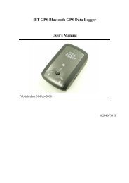
Mounting<br />
opening/groove<br />
(along both sides<br />
of unit - not shown)<br />
To mount the receiver:<br />
Figure 2-1: R320 receiver front view<br />
1. Locate the thumb screws, nuts, and brackets included in your R320<br />
kit.<br />
2. Slide the nuts through the openings (grooves) along both sides of<br />
the receiver.<br />
3. Place the bracket alongside the receiver and insert the thumbscrews<br />
so they screw into the nuts.<br />
4. Screw down the brackets.<br />
5. Install the receiver with brackets in the desired location.<br />
7
Chapter 2: Installing the R320<br />
Mounting the Antenna<br />
Antenna placement is crucial to the system’s operation. The GPS engine<br />
inside the R320 computes a position based on measurements from each<br />
satellite to the phase center of the antenna; therefore, mount the antenna at<br />
the location where the reference position should be.<br />
When considering the mounting location keep the following in mind:<br />
• Make sure the antenna has a clear view of the sky so that GPS<br />
satellites are not masked by obstructions (which may potentially<br />
reducing system performance)<br />
• Mount the antenna on, or as close to, the measurement center point<br />
• Position the antenna as high as possible<br />
You have the following options when mounting the antenna:<br />
• Magnetic mount<br />
• Pole mount<br />
Magnetic Mount<br />
The magnetic mount can be screwed into the bottom of the antenna and<br />
mounted to metal surfaces. The magnetic mount includes a metal disc and<br />
foam adhesive that allow you to bond the metal disc to the desired<br />
mounting location if there are no metal surfaces. You then place the<br />
magnetic mount on the metal disc.<br />
To attach the antenna using the magnetic mount:<br />
1. Clean and dry the surface where you will attach the metal disc.<br />
2. Remove the backing from one side of the foam adhesive and press<br />
the adhesive onto the mounting surface.<br />
3. Remove the backing from the other side of the foam adhesive and<br />
press the metal disc onto the mounting surface, applying firm<br />
pressure to ensure good adhesion.<br />
4. Place the magnetic mount (with antenna attached) on top of the<br />
metal disc.<br />
8
R320 Receiver <strong>User</strong> <strong>Guide</strong><br />
Pole Mount<br />
The center thread of the antenna is 5/8 inches for compatibility with a survey<br />
pole (not included). Simply thread the pole into the antenna.<br />
Connecting the Cables<br />
When connecting the cables from the R320 ensure the following:<br />
• Power cable must reach an appropriate power source<br />
• Antenna cable must reach from the antenna to the R320 receiver<br />
• Data cable may connect to a data storage device, computer, or other<br />
device that accepts GPS data<br />
When choosing a route for all R320 cables keep the following in mind:<br />
• Avoid running cables in areas of excessive heat<br />
• Keep cables away from corrosive chemicals<br />
• Do not run the extension cable through door or window jams<br />
• Keep cables away from rotating machinery<br />
• Do not crimp or excessively bend the cables<br />
• Avoid placing tension on the cables<br />
• Remove unwanted slack from the extension cable at the receiver<br />
end<br />
• Secure along the cable route using plastic wraps<br />
Improperly installed cables near machinery can be dangerous.<br />
9
Chapter 2: Installing the R320<br />
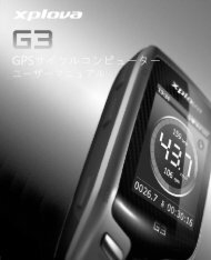
Connecting the R320 to External Devices<br />
Communication between the R320 and external devices occurs through two<br />
serial ports and two USB ports, as shown in Figure 2-2. You can configure<br />
the ports for a combination of NMEA 0183, binary, and/or RTCM SC-104 data.<br />
Serial<br />
ports<br />
USB port shared with Port A<br />
serial port (used to connect<br />
to external devices)<br />
USB port used for logging<br />
data via USB flash drive<br />
Figure 2-2: R320 serial and USB ports<br />
If you connect a device to Port A, Port B, or the top USB port you can<br />
transmit and receive data between the R320 and the device. Similarly, if you<br />
connect one device to Port B and another device to the top USB port you can<br />
transmit and receive data between the R320 and each device.<br />
Note: Port A is shared with the top USB port. If you connect a device to<br />
Port A and another device to the top USB port the receive functionality on<br />
Port A is disabled. Therefore, Hemisphere GPS recommends using Port B<br />
and the USB port if want to connect two devices to the R320.<br />
The top USB port is designed to be connected to a host device such as a PC.<br />
When you connect a PC to the R320 the PC should recognize it as a serial<br />
device and a new COM will appear as a valid connection on the PC. Set the<br />
communication software to use this new port to access the R320.<br />
The bottom USB port is used for data logging onto a USB flash drive. If your<br />
flash drive has a status LED it should light up when you plug it in. For further<br />
data logging options, see “Data Logging Menu” on page 49.<br />
10
R320 Receiver <strong>User</strong> <strong>Guide</strong><br />
Note: If you connect the supplied USB cable to the bottom USB port (data<br />
logging) or connect a USB flash drive to the top USB port (data<br />
communication), the USB functionality will not work as the USB ports are<br />
not interchangeable.<br />
The serial ports operate at the RS-232 interface level to<br />
communicate with external data loggers, navigation<br />
systems, and other devices. Either serial port can also<br />
be used for firmware updates. The figure to the right<br />
illustrates the numbering for the DB9 connector<br />
(female). The numbering for each plug connector (male)<br />
is a mirror reflection of the scheme to the right.<br />
Note: The baud rate for either R320 serial port and the device to which it is<br />
connected must match for successful communication. Table 2-1 provides the<br />
pin configuration for the serial ports.<br />
Table 2-1: Port A and Port B serial port pinouts<br />
Port A<br />
Port B<br />
Pin Function Pin Function<br />
1 Not connected 1 Not connected<br />
2 Transmit data Port A 2 Transmit data Port B<br />
3 Receive data Port A 3 Receive data Port B<br />
4 Not connected 4 Not connected<br />
5 Signal ground 5 Signal ground<br />
6 Not connected 6 Event marker<br />
7 Not connected 7 Not connected<br />
8 Not connected 8 Not connected<br />
9 5V output, 350 mA MAX 9 1 PPS<br />
11
Chapter 2: Installing the R320<br />
Configuring the Receiver<br />
You can configure many aspects of the R320 through either serial port using<br />
Hemisphere GPS commands. Refer to Hemisphere GPS’ GPS Technical<br />
Reference available from the Hemisphere GPS website for details.<br />
Note: Contact your Hemisphere GPS dealer for more information regarding<br />
configuration and the use of Hemisphere GPS commands.<br />
Environmental Considerations<br />
Although it is splash proof in case of accidental exposure the R320 is<br />
designed for indoor use. The antenna is designed for outdoor use. See<br />
Table B-4 on page 39 for the environmental specifications.<br />
Note: Changes you make to the R320 via either serial port are not<br />
automatically saved to memory for subsequent powerups; therefore, you<br />
must issue the $JSAVE command to save the changes. However, if you make<br />
changes via the menu system, they are automatically saved.<br />
12
Chapter 3: Operating the R320<br />
Powering the Receiver On/Off<br />
LED Indicators<br />
Using the Menus<br />
USB Data Logging
Chapter 3: Operating the R320<br />
T<br />
he R320 is designed for easy operation with LED indicators and a<br />
straightforward menu system. This chapter provides information on the<br />
following topics:<br />
• Powering the R320 on/off<br />
• LED indicators<br />
• R320 Main menu<br />
Powering the Receiver On/Off<br />
The power (ON/OFF) button of the R320 is located on the top panel.<br />
Figure 3-1: R320 Series power button<br />
The R320 accepts an input voltage of 8 to 36 VDC via the power cable. The<br />
supplied power should be continuous and clean for best performance.<br />
Table B-5 on page 40 provides the power specifications of the R320.<br />
Do not provide a voltage higher than the input range (36 VDC).<br />
This will damage the receiver and void the warranty.<br />
Do not attempt to operate the R320 with the fuse bypassed.<br />
This will void the warranty.<br />
14
R320 Receiver <strong>User</strong> <strong>Guide</strong><br />
The R320 features reverse polarity protection to prevent damage if the<br />
power leads are accidentally reversed. Although the R320 proceeds through<br />
an internal startup sequence when you apply power, it will be ready to<br />
communicate immediately.<br />
Note: The initial startup may take 5 to 15 minutes depending on the<br />
location. Subsequent startups will output a valid position within 1 to 5<br />
minutes depending on the location and time since the last startup.<br />
Note: The R320 may take up to 5 minutes to receive a full ionospheric map<br />
from SBAS. Optimum accuracy is obtained once the R320 is processing<br />
corrected positions using complete ionospheric information.<br />
To power on the R320:<br />
1. Connect the ends of the R320 power cable to a clean power source<br />
providing 8 to 36 VDC.<br />
Note: Hemisphere GPS suggests you use a weathertight<br />
connection and connector if the connection is located outside.<br />
2. Press the ON/OFF button on the top panel.<br />
To power off the R320:<br />
• Press the ON/OFF button on the top panel.<br />
15
Chapter 3: Operating the R320<br />
LED Indicators<br />
The R320 Series uses LEDs to indicate power, GPS lock, and DGPS position.<br />
There is a corresponding icon below each LED. Table 3-1 describes each LED<br />
indicator.<br />
Table 3-1: LED indicators<br />
LED Indicator LED Color Description/Function<br />
Red<br />
Power indicator<br />
Illuminates solid red when the receiver is<br />
powered on.<br />
Yellow<br />
GPS lock indicator<br />
Illuminates solid yellow when the receiver<br />
achieves a solid GPS lock.<br />
Green<br />
DGPS position indicator<br />
Illuminates solid green when the receiver<br />
achieves a differential position and a<br />
pseudorange residual of better than the value<br />
specified by the $JLIMIT command (default is<br />
10.0 m or 32.8 ft).<br />
If the residual value is worse than the current<br />
threshold, the LED blinks green indicating<br />
differential mode has been attained but the<br />
residual has not met the threshold.<br />
16
R320 Receiver <strong>User</strong> <strong>Guide</strong><br />
Using the Menus<br />
The R320 menu system is designed for easy setup and configuration of the<br />
unit in or out of the field and supports multiple languages. You can perform<br />
most configuration tasks entirely through the menu without having to<br />
connect to a computer or PDA.<br />
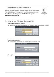
Channel bars<br />
Figure 3-2: R320 menu<br />
The bars along the top left of the display offer a visual representation of each<br />
channel's tracking status (one bar section for each channel). Depending on<br />
what signals you're tracking, the bars represent something different, where:<br />
• If you're tracking L1 GPS only, each bar represents L1 GPS.<br />
• If you're tracking L1/L2 GPS, each bar is two separate bars (starting<br />
from the left, first bar for L1 GPS, second bar for L2 GPS)<br />
• If you're tracking L1/L2 GPS and GLONASS, each bar is four<br />
separate bars (starting from the left, first bar for L1 GPS, second bar<br />
for L2 GPS, third bar for L1 GLONASS, fourth bar for L2 GLONASS)<br />
Refer to Appendix C, “Menu Maps” for a complete menu map for the<br />
following options on the Main menu:<br />
• GPS<br />
• Differential corrections (menu item will be the selected differential<br />
source, such as SBAS or Autonomous)<br />
• Configuration Wizard<br />
• System Setup<br />
• Data Logging<br />
17
Chapter 3: Operating the R320<br />
The R320 front panel contains three soft buttons: Up, Enter, and Down (see<br />
Figure 3-3).<br />
Up button - moves to the previous menu item or<br />
to the previous selection within a menu item<br />
Enter button - displays a submenu or selects an<br />
option within a menu item<br />
Down button - moves to the next menu item or<br />
to the next selection within a menu item<br />
Figure 3-3: Menu buttons<br />
18
R320 Receiver <strong>User</strong> <strong>Guide</strong><br />
Table 3-2 describes the indicators that appear to the right of specific menu<br />
items.<br />
Table 3-2: Menu item indicators<br />
Indicator Purpose Example<br />
Display<br />
indicator<br />
Select<br />
indicator<br />
Go to the indicated<br />
submenu<br />
This indicator also appears<br />
to the right of the “Back”<br />
and “Top Menu” menu<br />
items.<br />
• Pressing Enter<br />
when “Back” is<br />
selected returns<br />
you to the previous<br />
menu.<br />
• Pressing Enter<br />
when “Top Menu”<br />
is selected returns<br />
you to the Main<br />
menu.<br />
Scrolls within a menu to<br />
highlight an option to<br />
select.<br />
1. On the Main menu press the<br />
Down button to highlight System<br />
Setup. The Display indicator<br />
appears to the right of System<br />
Setup.<br />
2. Press Enter to display the System<br />
Setup menu.<br />
3. Press the Down button again to<br />
highlight the Display Format<br />
option and then press Enter. The<br />
items on the Display Format<br />
menu appear and the Select<br />
indicator appears to the right of<br />
Disp Update (the first item on the<br />
Display Format menu).<br />
4. Press Enter on the Disp Update<br />
item. The Display indicator<br />
changes to the Select indicator.<br />
5. Press the Up or Down buttons to<br />
scroll through the available<br />
options (such as 1Hz and 5Hz).<br />
6. Press Enter on the highlighted<br />
option to select it. That option is<br />
now the setting for the menu item<br />
and the Select indicator changes<br />
back to the Display indicator.<br />
To return the menu system to the factory default configuration:<br />
• While holding down Enter power up the receiver until the splash<br />
screen disappears.<br />
19
Chapter 3: Operating the R320<br />
Menu and Menu Item Selection in This <strong>User</strong> <strong>Guide</strong><br />
For many instructions in this <strong>User</strong> <strong>Guide</strong> the following example illustrates<br />
the nomenclature used for making navigating the menus:<br />
“On the Main menu select Data Logging > Config” is the equivalent to<br />
saying “On the Main menu select Data Logging and press Enter. Then<br />
select Config and press Enter.”<br />
When making selections for a menu item, such as selecting Yes or No for<br />
Auto-Name (Data Logging > Config menu), the instructions will indicate to<br />
select the menu item and press Enter to allow you to then select an option<br />
for that menu item and then press Enter again to select that option.<br />
20
R320 Receiver <strong>User</strong> <strong>Guide</strong><br />
USB Data Logging<br />
When you insert a USB flash drive into the R320, the Data Logging menu<br />
indicates you can start recording (logging data) and displays the free space<br />
on the flash drive (see Figure 3-4). When you start logging data the “Start<br />
Recording” indicator changes to “End .”<br />
<br />
<br />
<br />
<br />
With no USB flash<br />
drive inserted<br />
<br />
<br />
<br />
<br />
<br />
With USB flash<br />
drive inserted<br />
Figure 3-4: USB flash drive indicators on Data Logging menu<br />
Stop data logging before removing the USB flash drive from<br />
the R320. Failure to do so may result in a loss of data.<br />
Data Logging Formats<br />
You can log the following data types to a USB flash drive:<br />
• RAW - Binary, NMEA, and other data options (see Table 3-3)<br />
• KML - Google Earth KML format with latitude, longitude and height<br />
• CSV - Comma-separated value (CSV) format with time, latitude,<br />
longitude, and height<br />
Table 3-3: RAW data log options<br />
Format<br />
Raw (binary)<br />
Description<br />
For raw (binary) data logging, you may also want the receiver<br />
configuration to be inserted into the file. If you select this option the<br />
file will start with the receiver configuration comprised of the replies<br />
to the $JI, $JK, $JT, and $JSHOW queries.<br />
21
Chapter 3: Operating the R320<br />
Table 3-3: RAW data log options<br />
Format<br />
NMEA<br />
CMR<br />
DFX<br />
ROX<br />
RTCM<br />
Description<br />
National Marine Electronics Association (NMEA 0183) - industry<br />
standard data transmission format<br />
Trimble-proprietary data correction format<br />
Hemisphere GPS-proprietary data correction format<br />
Hemisphere GPS-proprietary data correction format<br />
Radio Technical Commission for Maritime Services - industry<br />
standard data correction format<br />
22
R320 Receiver <strong>User</strong> <strong>Guide</strong><br />
When logging using the RAW data type (File Type > RAW as shown in<br />
Figure 3-5) you can select which data to log and at what rate by selecting<br />
Data Logs and then making the desired selections on the Data Logs menu.<br />
<br />
<br />
<br />
<br />
<br />
<br />
<br />
<br />
<br />
<br />
<br />
<br />
<br />
<br />
<br />
<br />
<br />
<br />
<br />
<br />
<br />
<br />
<br />
<br />
<br />
<br />
<br />
<br />
<br />
<br />
<br />
<br />
<br />
<br />
<br />
<br />
<br />
<br />
<br />
<br />
<br />
<br />
Figure 3-5: Data Logging > Config > Data Logs menu<br />
Note: Logged data options are limited by your receiver subscriptions<br />
(certain options may not appear on the Data Logs menu without a specific<br />
subscription). For example, GNGNS, GNGSA, GLGSV, Bin62, Bin65, Bin66,<br />
and Bin69 only appear on the Data Logs menu if you are authorized to<br />
receive GLONASS. To view your subscriptions press System Setup ><br />
Subscription.<br />
23
Chapter 3: Operating the R320<br />
Logging Data to a File<br />
You can log data to a file that the R320 auto-generates or you can manually<br />
enter a filename to which to log data. You can append data to or overwrite<br />
data on a manually-named file; however, you cannot append data to or<br />
overwrite data on an R320-generated file.<br />
To log data to an R320 auto-generate filename:<br />
1. Select Data Logging > Config.<br />
2. If Auto-Name displays “No” select Auto-Name and then press<br />
Enter.<br />
3. Select Yes and then press Enter.<br />
4. Select Back to return to the Data Logging menu.<br />
5. Select Start Recording to begin logging data. The “Start<br />
Recording” option changes to “End ”.<br />
6. Select End .<br />
To log data to a manually-created filename:<br />
1. Select Data Logging > Config.<br />
2. If Auto-Name displays “Yes” select Auto-Name and then press<br />
Enter.<br />
3. Select No and press Enter.<br />
The “Enter Name” and “Mode” menu items appear below<br />
“Auto-Name.”<br />
4. Enter a filename:<br />
a. Select Enter Name and press Enter.<br />
b. Enter the desired characters for the filename and then scroll to<br />
the return character and press Enter.<br />
5. Select the mode:<br />
a. Select Mode and press Enter.<br />
b. Select Append to log data to new file or to append data to an<br />
existing file (based on the filename in step 4) and press Enter.<br />
or<br />
24
R320 Receiver <strong>User</strong> <strong>Guide</strong><br />
Select Overwrite to overwrite an existing file (based on the<br />
filename in step 4) and press Enter.<br />
No warnings are given to confirm overwriting a<br />
previous file.<br />
Data Post-Processing<br />
After you log data you can then process the data with a Receiver<br />
Independent Exchange (RINEX) format software utility.<br />
To post-process raw data:<br />
1. Log the RAW data (see Table 3-3 for data options) to the USB flash<br />
drive that is connected to the R320.<br />
2. Remove the flash drive from the R320 and connect it to a PC with<br />
Hemisphere GPS’ Rinex conversion software installed.<br />
Note: The Hemisphere GPS Rinex conversion software is available<br />
from the Hemisphere GPS website at www.hemispheregps.com.<br />
3. Run the Rinex conversion software.<br />
Note: For the latest information on using the Hemisphere GPS<br />
Rinex software see the Hemisphere GPS Technical Reference<br />
available from the Hemisphere GPS website at<br />
www.hemispheregps.com.<br />
25
Chapter 4: Using GNSS Differential<br />
Corrections<br />
Installing the Base Station<br />
Installing the Rover Radio<br />
Using the Receiver as a Base Station or Rover<br />
RTK Operation<br />
Using OmniSTAR
Chapter 4: Using GNSS Differential Corrections<br />
R<br />
TK is a differential options that provides the highest accuracy (see<br />
Table B-2 on page 39 for accuracy specifications). A local base station<br />
is required, with the base station and rover each typically comprised of<br />
the following:<br />
• GNSS receiver<br />
• GNSS antenna<br />
• Radio: transmitter for base station, receiver for rover<br />
• Power source<br />
Installing the Base Station<br />
The base station tracks GNSS signals and broadcasts differential corrections<br />
to a radio and rover GNSS receiver. You typically set up the base station near<br />
the working area and at a location with no obstructions between the base<br />
station and rover radio.<br />
When installing the base station ensure the following:<br />
• Base station is not placed near metal objects<br />
• Base station is at least 50 m (160 ft) from obstructions<br />
• Base station and rover radio have a clear line of sight up to 5 km<br />
(3 mi) or less depending on the radio type when operating RTK<br />
Installing the Rover Radio<br />
The rover GNSS system processes the corrections and outputs highly<br />
accurate position information.<br />
When installing the rover radio ensure the following:<br />
• Rover radio and GNSS antenna are at least 1 m (3 ft) apart<br />
• Rover radio must not block the GNSS antenna<br />
• Rover radio must receive regular corrections from the base station<br />
every one to two seconds (differential age) for up to 15 minutes to<br />
achieve RTK lock (maximum accuracy) - typically, a lock is achieved<br />
in less than five minutes<br />
28
R320 Receiver <strong>User</strong> <strong>Guide</strong><br />
Using the Receiver as a Base Station or Rover<br />
Using the R320 as a base station or rover receiver requires a subscription and<br />
a link between base and rover to transfer differential correction data from<br />
base to rover. The link can be wired or wireless (such as a radio modem).<br />
Setting Up the Receiver as a Base Station or Rover<br />
Make sure the current R320 application is set to SBASRTKB for a base station<br />
or RTK for a rover.<br />
Step<br />
Button (where<br />
applicable)<br />
1. On the Main menu press the Up or Down arrow until System<br />
Setup is highlighted.<br />
2. Press Enter. The System Setup menu appears with Display<br />
Apps highlighted.<br />
3. With Display Apps highlighted press Enter.<br />
Make sure In Use: displays as either:<br />
• SBASRTKB for an RTK base station<br />
• RTK for an RTK rover receiver<br />
If the RTK application only appears next to Other:, scroll<br />
down and select Swap Applications. The desired<br />
application will then be shown as In Use.<br />
29
Chapter 4: Using GNSS Differential Corrections<br />
Connecting the Receiver to a PC<br />
You can also select the appropriate application using a terminal program<br />
such as Hyper Terminal ® , SLXMon, or PocketMAX TM .<br />
When using direct commands from a PC, send the $JAPP command to view<br />
the current application. A response such as $>JAPP,SBASRTKB,RTK,1,2 will<br />
appear, indicating the SBASRTKB application is active and RTK is the<br />
secondary application. If the application was different and RTK was first,<br />
such as $>JAPP,RTK,SBASRTKB,2,1, then send $JAPP,other to swap<br />
applications so the correct application is used.<br />
Step<br />
Button (where<br />
applicable)<br />
1. Connect either Port A or the upper USB port (data<br />
communication) of the R320 receiver to the serial port of the<br />
PC using the 9-pin serial cable.<br />
2. Configure the port communication parameters on the<br />
receiver.<br />
a. On the Main menu press the Up or Down arrows to<br />
highlight System Setup and then press Enter.<br />
b. Press the Up or Down arrows to highlight ‘Baud Rates’<br />
and then press Enter.<br />
c. Press the Up or Down arrows to highlight the desired<br />
baud rate and then press Enter.<br />
Up/Down<br />
arrows<br />
Enter<br />
See “System Setup Menu” on page 44 for more information.<br />
3. Ensure the connected serial port on the PC has matching<br />
communication parameters.<br />
30
R320 Receiver <strong>User</strong> <strong>Guide</strong><br />
Connecting the Receiver to an External Device or Base/Rover<br />
Radio<br />
You can connect the R320 to an external device or a base/rover radio. Before<br />
selecting an external device or base or radio system, ensure it meets the<br />
following requirements:<br />
• Does not interfere with GPS<br />
• Serial connection, with a minimum of 9600 baud, set to N,8,1<br />
• Over the air throughput of at least 300 bps<br />
Step<br />
Button (where<br />
applicable)<br />
1. Connect either Port A or the upper USB port (data<br />
communication) of the R320 receiver to the serial port of the<br />
device using the 9-pin serial cable.<br />
2. Configure the port communication parameters on the<br />
receiver.<br />
a. On the Main menu press the Up or Down arrows to<br />
highlight System Setup and then press Enter.<br />
b. Press the Up or Down arrows to highlight ‘Baud Rates’<br />
and then press Enter.<br />
c. Press the Up or Down arrows to highlight the desired<br />
baud rate and then press Enter.<br />
Up/Down<br />
arrows<br />
Enter<br />
See “System Setup Menu” on page 44 for more information.<br />
3. Ensure the device has matching communication parameters<br />
for the connecting port.<br />
Note: Hemisphere GPS recommends testing with a wired condition prior to<br />
using a radio connection to ensure communication parameters are properly<br />
defined. Also, make sure both the rover radio and base station are on the<br />
same channel or frequency so the rover radio can receive corrections from<br />
the base station.<br />
31
Chapter 4: Using GNSS Differential Corrections<br />
RTK Operation<br />
After you connect the receiver to the desired devices and are operating<br />
using RTK, the status LEDs indicate the following:<br />
• Yellow: tracking GPS<br />
• Flashing green: differential has been attained, but the residual has<br />
not met the threshold<br />
• Solid green: RTK lock<br />
The R320 will output standard NMEA messages through Port A as desired.<br />
Set the message and port output as desired.<br />
32
R320 Receiver <strong>User</strong> <strong>Guide</strong><br />
Using OmniSTAR<br />
OmniSTAR is a worldwide terrestrial DGPS service that provides correction<br />
data to subscribers of the system with the use of a geostationary<br />
transponder. With this service, the positioning accuracy does not degrade as<br />
a function of distance to a base station, as the data content is not composed<br />
of a single base station’s information, but an entire network’s information.<br />
The information broadcast by this service is based upon a network of<br />
reference stations placed at geographically strategic locations. The network<br />
stations communicate GPS correction data to control centers where it is<br />
decoded, checked, and repackaged into a proprietary format for<br />
transmission to a geostationary L-band communications satellite. The<br />
satellite rebroadcasts the correction information back to earth over a large<br />
signal footprint where the R320’s L-band differential satellite receiver<br />
demodulates the data. The resulting corrections are those that would be<br />
calculated if a reference station were set up at the present location. This type<br />
of solution ensures a consistent level of accuracy across the entire coverage<br />
area.<br />
OmniSTAR Reception<br />
The OmniSTAR service broadcasts at a similar frequency to GPS, and as a<br />
result, is a line-of-sight system. There must be a line of sight between the<br />
antenna and the OmniSTAR satellite for reception of the service. The<br />
OmniSTAR service uses geostationary satellites for communication. The<br />
elevation angle to these satellites is dependent upon latitude. For latitudes<br />
higher than approximately 55° north or south, the OmniSTAR signal may be<br />
blocked more easily by obstructions such as trees, buildings, terrain, or other<br />
objects.<br />
OmniSTAR Service Activation<br />
The OmniSTAR service may be activated by contacting the service provider<br />
in the your region. Contact OmniSTAR with the unit number and they will<br />
activate the subscription over the air. Please have the receiver ready to<br />
receive the OmniSTAR signal for subscription validation.<br />
For questions regarding the OmniSTAR service, contact OmniSTAR for<br />
further information.<br />
33
Chapter 4: Using GNSS Differential Corrections<br />
Contacting OmniSTAR<br />
Table 4-1 provides the contact numbers for the various OmniSTAR offices<br />
throughout the world.<br />
Table 4-1: OmniSTAR contact information<br />
Location Telephone Number Website<br />
North America<br />
South America<br />
Europe<br />
North Africa<br />
Middle East<br />
West Asia<br />
Australia<br />
Far East<br />
1-888-883-8476 www.omnistar.com<br />
31-70-317-0900 www.omnistar.nl<br />
61-8-9322-5295 http://omnistar.com.au<br />
Southern Africa 27-21-527-8950 www.omnistar.co.za<br />
34
Appendix A: Troubleshooting
Appendix A: Troubleshooting<br />
Table A-1 provides a checklist to troubleshoot common issues and their<br />
solutions for the R320.<br />
Table A-1: Troubleshooting<br />
Issues<br />
Possible solution<br />
Receiver fails to power • Verify polarity of power leads<br />
• Check integrity of power cable connections<br />
• Check power input voltage (8 - 36 VDC)<br />
• Check current restrictions imposed by power source<br />
(maximum is 575 mA @ 12 VDC)<br />
• Press the POWER button<br />
No data from R320 • Check receiver power status (red LED)<br />
• Check integrity and connectivity of power and data<br />
cable connections<br />
• The volume of data requested to be output by the<br />
R320 could be higher than what the current baud rate<br />
supports. Try using 19200 or higher as the baud rate<br />
for all devices.<br />
No GPS lock • Check integrity of cable connections<br />
• Verify antenna’s clear view of the sky<br />
No SBAS lock • Check integrity of cable connections<br />
• Verify antenna’s clear view of the sky<br />
• Check SBAS visibility map<br />
No OmniSTAR lock • Subscription activated and not expired<br />
• Check antenna connections<br />
• Verify antenna’s clear view of the sky<br />
36
Appendix B: Specifications
Appendix B: Specifications<br />
Table B-1 through Table B-6 provide the power, mechanical, communication,<br />
environmental and DGPS specifications for the R320.<br />
Table B-1: GNSS sensor specifications<br />
Item<br />
Receiver type<br />
Channels<br />
SBAS tracking<br />
Update rate<br />
Timing (1PPS) accuracy<br />
Cold start<br />
Warm start<br />
Hot start<br />
Maximum speed<br />
Maximum altitude<br />
Differential options<br />
Satellite reacquisition<br />
Specification<br />
GNSS L1 & L2 RTK with carrier phase<br />
12 L1CA GPS<br />
12 L1P GPS<br />
12 L2P GPS<br />
12 L2C GPS<br />
12 L1 GLONASS (with subscription code)<br />
12 L2 GLONASS (with subscription code)<br />
3 SBAS or 3 additional L1CA GPS<br />
1 L-Band<br />
3-channel, parallel tracking<br />
10 Hz standard, 20 Hz available<br />
20 ns<br />
< 60 s typical (no almanac or RTC)<br />
< 30 s typical (almanac and RTC)<br />
< 10 s typical (almanac, RTC, and position)<br />
1,850 kph (999 kts)<br />
18,288 m (60,000 ft)<br />
SBAS, Autonomous, External RTCM, RTK,<br />
OmniSTAR (G2/HP/XP/VBS)<br />
< 1 s<br />
38
R320 Receiver <strong>User</strong> <strong>Guide</strong><br />
Table B-2: Horizontal accuracy specifications<br />
Item RMS (67%) 2DRMS (95%)<br />
RTK 2,3 10 mm + 1 ppm 20 mm + 2 ppm<br />
OmniSTAR HP 2,4 0.1 m 0.2 m<br />
SBAS (WAAS) 2 0.3 m 0.6 m<br />
Autonomous, no SA 2 1.2m 2.5m<br />
Table B-3: Communication specifications<br />
Item<br />
Serial ports<br />
USB ports<br />
Specification<br />
2 full-duplex RS-232<br />
1 USB host, 1 USB device<br />
Baud rates 4800 - 115200<br />
Correction I/O protocol<br />
Data I/O protocol<br />
Timing output<br />
Event marker input<br />
Hemisphere GPS proprietary, RTCM v2.3 (DGPS),<br />
RTK v3, CMR, CMR+ 1<br />
NMEA 0183, Hemisphere GPS binary<br />
1 PPS (HCMOS, active high, rising edge sync, 10 kΩ,<br />
10 pF load)<br />
HCMOS, active low, falling edge sync, 10 kΩ<br />
Table B-4: Environmental specifications<br />
Item<br />
Operating temperature<br />
Storage temperature<br />
Humidity<br />
Shock and vibration<br />
Specification<br />
-40°C to +70°C (-40°F to +158°F)<br />
-40°C to +85°C (-40°F to +185°F)<br />
95% non-condensing<br />
Vibration: EP455 Section 5.15.1 Random<br />
Mechanical Shock: EP455 Section 5.14.1<br />
Operational<br />
EMC CE (IEC 60945 Emissions and Immunity), FCC Part 15,<br />
Subpart B, CISPR22<br />
39
Appendix B: Specifications<br />
Table B-5: Power specifications<br />
Item<br />
Input voltage<br />
Power consumption<br />
Current consumption<br />
Antenna voltage input<br />
Antenna short circuit protection<br />
Antenna gain input range<br />
Antenna input impedance<br />
Specification<br />
8 to 36 VDC<br />
< 4.3 W nominal (using L-Band)<br />
< 3.5 W nominal (no L-Band)<br />
355 mA nominal (@ 12 VDC using L-Band)<br />
295 mA nominal (@ 12 VDC no L-Band)<br />
15 VDC maximum<br />
Yes<br />
10 to 40 dB<br />
50 Ω<br />
Table B-6: Receiver mechanical specifications<br />
Item<br />
Dimensions<br />
Weight<br />
Status indication (LED)<br />
Power/data connector<br />
Antenna connector<br />
Specification<br />
178 L x 120 W x 46 H (mm)<br />
7.01 L x 4.72 W x 1.81 H (in)<br />
0.64 kg (1.4 lbs)<br />
Power, GPS lock, Differential lock, DGPS position,<br />
L-Band lock<br />
2-pin metal ODU connector<br />
TNC-male, straight<br />
1 Receive only, does not transmit this format.<br />
2 Depends on multipath environment, number of satellites in view, satellite<br />
geometry and ionospheric activity.<br />
3 Depends also on baseline length.<br />
4 Requires a subscription from OmniSTAR.<br />
40
Appendix C: Menu Maps<br />
GPS/GNSS Menu<br />
Differential Corrections Menu<br />
Base Station Menu<br />
Configuration Wizard Menu<br />
System Setup Menu<br />
Data Logging Menu
Appendix C: Menu Maps<br />
This appendix shows the complete menu map for each menu (listed below)<br />
on the R320 main screen.<br />
• GPS/GNSS<br />
• Differential Corrections (menu item will be the selected differential<br />
source, such as SBAS or Autonomous)<br />
• Base Station<br />
• Configuration Wizard<br />
• System Setup<br />
• Data Logging<br />
42
R320 Receiver <strong>User</strong> <strong>Guide</strong><br />
GPS/GNSS Menu<br />
Use the GPS menu to view and edit GPS settings. If GLONASS is enabled on<br />
your receiver, use the GNSS menu to view and edit your GPS and GLONASS<br />
settings. Settings include the data port outputs, specific positioning<br />
parameters, UTC time offset, and satellite visibility and positioning<br />
information.<br />
If you have not enabled<br />
GLONASS, the first menu item<br />
on the main menu is GPS.<br />
<br />
<br />
<br />
<br />
<br />
<br />
<br />
<br />
<br />
<br />
<br />
<br />
If you set up the receiver as a<br />
rover unit, “Base Station” will<br />
not appear on the main menu.<br />
<br />
<br />
<br />
<br />
<br />
<br />
<br />
<br />
<br />
<br />
<br />
<br />
<br />
<br />
<br />
<br />
<br />
<br />
<br />
<br />
<br />
<br />
<br />
<br />
<br />
<br />
<br />
<br />
<br />
<br />
<br />
<br />
<br />
<br />
<br />
<br />
<br />
<br />
<br />
<br />
<br />
<br />
<br />
<br />
<br />
<br />
<br />
<br />
<br />
<br />
<br />
<br />
<br />
<br />
<br />
<br />
<br />
<br />
<br />
<br />
<br />
<br />
<br />
<br />
<br />
<br />
<br />
<br />
Figure C-1: GPS/GNSS menu<br />
43
Appendix C: Menu Maps<br />
Differential Corrections Menu<br />
Use the differential corrections menu to view your differential settings. The<br />
differential name shown on the main menu of the display reflects your<br />
current differential source. For example, if you are using SBAS, then “SBAS”<br />
appears on the main screen and the associated SBAS submenus are<br />
available, as shown in Figure C-2.<br />
<br />
<br />
<br />
<br />
<br />
<br />
<br />
<br />
<br />
<br />
<br />
<br />
<br />
<br />
<br />
<br />
<br />
<br />
<br />
<br />
<br />
<br />
<br />
<br />
<br />
<br />
<br />
<br />
<br />
<br />
<br />
Figure C-2: SBAS menu<br />
The following available differential sources depend on the configuration you<br />
purchased:<br />
• SBAS<br />
• L-Band<br />
• External RTCM<br />
• Autonomous<br />
From the differential corrections menu, you can view your current status or<br />
adjust satellites tracked.<br />
44
R320 Receiver <strong>User</strong> <strong>Guide</strong><br />
Figure C-3 through Figure C-5 show the complete menu maps for the<br />
L-Band, External RTCM, and Autonomous differential sources, respectively.<br />
<br />
<br />
<br />
<br />
<br />
<br />
<br />
<br />
<br />
<br />
<br />
<br />
<br />
<br />
<br />
<br />
<br />
<br />
<br />
<br />
<br />
<br />
<br />
<br />
<br />
<br />
<br />
<br />
<br />
<br />
<br />
<br />
<br />
<br />
<br />
Figure C-3: L-Band menu<br />
<br />
<br />
<br />
<br />
<br />
<br />
<br />
<br />
<br />
<br />
<br />
Figure C-4: External RTCM menu<br />
45
Appendix C: Menu Maps<br />
<br />
<br />
<br />
<br />
<br />
<br />
<br />
<br />
<br />
<br />
Base Station Menu<br />
Figure C-5: Autonomous menu<br />
The Base Station menu allows you to configure the base station/rover setup.<br />
<br />
<br />
<br />
<br />
<br />
<br />
<br />
<br />
<br />
<br />
<br />
<br />
<br />
<br />
<br />
<br />
<br />
<br />
<br />
<br />
<br />
<br />
<br />
<br />
<br />
<br />
Figure C-6: Base Station menu<br />
46
R320 Receiver <strong>User</strong> <strong>Guide</strong><br />
Configuration Wizard Menu<br />
The Configuration Wizard walks you through basic settings to get started.<br />
Logged data options are limited by<br />
your receiver subscriptions (certain<br />
options may not appear on this menu<br />
without a specific subscription. For<br />
example, GNGNS, GNGSA, GLGSV,<br />
Bin62, Bin65, Bin66, and Bin69 only<br />
appear on this menu if you are<br />
authorized to receiver GLONASS.<br />
<br />
<br />
<br />
<br />
<br />
<br />
<br />
<br />
<br />
<br />
<br />
<br />
<br />
<br />
<br />
<br />
<br />
<br />
<br />
<br />
<br />
<br />
<br />
<br />
<br />
<br />
<br />
<br />
<br />
<br />
<br />
<br />
<br />
<br />
<br />
<br />
<br />
<br />
<br />
<br />
<br />
<br />
<br />
<br />
<br />
<br />
<br />
<br />
<br />
<br />
<br />
<br />
<br />
<br />
<br />
<br />
<br />
<br />
<br />
<br />
<br />
<br />
<br />
<br />
<br />
<br />
<br />
<br />
<br />
<br />
<br />
<br />
<br />
<br />
<br />
<br />
<br />
<br />
<br />
<br />
<br />
<br />
<br />
<br />
<br />
<br />
<br />
<br />
<br />
<br />
<br />
<br />
<br />
<br />
<br />
<br />
<br />
<br />
<br />
<br />
<br />
<br />
<br />
Figure C-7: Config Wizard menu<br />
47
Appendix C: Menu Maps<br />
System Setup Menu<br />
The System Setup menu allows you to view and edit such current system<br />
settings as current applications, units, baud rates, logs, LED contrast,<br />
subscription code, display orientation (you can flip the display 180° by<br />
selecting “YES” under FLIP DISPLAY), and language.<br />
<br />
<br />
<br />
<br />
<br />
<br />
<br />
<br />
<br />
<br />
<br />
<br />
<br />
<br />
<br />
<br />
<br />
<br />
<br />
<br />
<br />
<br />
<br />
<br />
<br />
<br />
<br />
<br />
<br />
<br />
<br />
<br />
<br />
<br />
<br />
<br />
<br />
<br />
<br />
<br />
<br />
<br />
<br />
<br />
<br />
<br />
<br />
<br />
Figure C-8: System Setup menu<br />
48
R320 Receiver <strong>User</strong> <strong>Guide</strong><br />
Data Logging Menu<br />
The Data Logging menu allows you to log or output job data, view USB flash<br />
drive free storage space, set up file auto-naming, and view what type of data<br />
you are logging.<br />
<br />
<br />
<br />
<br />
<br />
<br />
Logged data options are limited by<br />
your receiver subscriptions (certain<br />
options may not appear on this menu<br />
without a specific subscription. For<br />
example, GNGNS, GNGSA, GLGSV,<br />
Bin62, Bin65, Bin66, and Bin69 only<br />
appear on this menu if you are<br />
authorized to receiver GLONASS.<br />
<br />
<br />
<br />
<br />
<br />
<br />
<br />
<br />
<br />
<br />
<br />
<br />
<br />
<br />
<br />
<br />
<br />
<br />
<br />
<br />
<br />
<br />
<br />
<br />
<br />
<br />
<br />
<br />
<br />
<br />
<br />
<br />
<br />
<br />
<br />
<br />
<br />
<br />
<br />
<br />
<br />
<br />
<br />
<br />
<br />
<br />
<br />
Figure C-9: Data Logging menu<br />
49
R320 Receiver <strong>User</strong> <strong>Guide</strong><br />
Index<br />
A<br />
activating OmniSTAR 33<br />
antenna<br />
magnetic mount 8<br />
mounting overview 8<br />
pole mount 9<br />
Autonomous menu map 46<br />
B<br />
base station<br />
installing 28<br />
using receiver as 29<br />
Base Station menu map 46<br />
binary/raw (RAW data option) 21<br />
C<br />
cables<br />
connecting to receiver 9<br />
CMR (RAW data option) 22<br />
COAST 2<br />
communication specifications 39<br />
Configuration Wizard<br />
menu map 47<br />
configuring the receiver 12<br />
connecting<br />
cables to receiver 9<br />
external devices to receiver 10<br />
contacting (OmniSTAR) 34<br />
CSV data format 21<br />
D<br />
data logging<br />
formats 21<br />
overview 21<br />
post-processing 25<br />
Data Logging menu map 49<br />
DFX (RAW data option) 22<br />
DGPS position indicator LED 16<br />
Diff (differential source) menu map 44<br />
differential corrections 28<br />
display indicator 19<br />
Down button 18<br />
E<br />
Eclipse II 2<br />
Enter button 18<br />
environmental considerations 12<br />
environmental specifications 39<br />
external devices<br />
connecting to receiver 10<br />
connecting to receiver for base station/rover<br />
setup 31<br />
External RTCM menu map 45<br />
G<br />
GLONASS 2<br />
GNSS sensor specifications 38<br />
GPS lock indicator LED 16<br />
GPS/GNSS menu map 43<br />
H<br />
horizontal accuracy specifications 39<br />
I<br />
installing<br />
base station 28<br />
rover 28<br />
51
Index<br />
K<br />
KML data format 21<br />
L<br />
L1/L2 2<br />
L-Band menu map 45<br />
LED indicators 16<br />
logging data to a file (instructions) 24<br />
M<br />
magnetic mount (antenna) 8<br />
mechanical specifications 40<br />
menu map<br />
Autonomous 46<br />
Base Station 46<br />
Configuration Wizard 47<br />
Data Logging 49<br />
Diff (differential source) 44<br />
External RTCM 45<br />
GPS/GNSS 43<br />
L-Band 45<br />
SBAS 44<br />
System Setup 48<br />
menus 17<br />
buttons 18<br />
item indicators 19<br />
mounting<br />
antenna 8<br />
antenna (magnetic mount) 8<br />
antenna (pole mount) 9<br />
receiver 6<br />
N<br />
NMEA (RAW data option) 22<br />
O<br />
OmniSTAR 2<br />
activation 33<br />
contact information 34<br />
overview 33<br />
reception 33<br />
P<br />
parts list 3<br />
PC connection for base station/rover 30<br />
PC connection for base station/rover setup<br />
30<br />
pinouts<br />
serial ports 11<br />
pole mount (antenna) 9<br />
post-processing data 25<br />
power indicator LED 16<br />
power specifications 40<br />
powering receiver on/off 14<br />
R<br />
R320<br />
parts list 3<br />
what’s included 3<br />
RAW data format 21<br />
receiver<br />
communication specifications 39<br />
configuring 12<br />
connecting cables 9<br />
connecting to external device for base<br />
station/rover setup 31<br />
connecting to external devices 10<br />
connecting to PC for base station/rover<br />
setup 30<br />
environmental considerations 12<br />
environmental specifications 39<br />
GNSS sensor specifications 38<br />
horizontal accuracy specifications 39<br />
LED indicators 16<br />
logging data 21<br />
mechanical specifications 40<br />
menus 17<br />
mounting 6<br />
power specifications 40<br />
52
R320 Receiver <strong>User</strong> <strong>Guide</strong><br />
powering on/off 14<br />
troubleshooting 36<br />
using as base station 29<br />
using as rover 29<br />
reception (OmniSTAR) 33<br />
rover<br />
installing 28<br />
using receiver as 29<br />
ROX (RAW data option) 22<br />
RTCM (RAW data option) 22<br />
RTK<br />
operation 32<br />
typical requirements 28<br />
S<br />
SBAS menu map 44<br />
select indicator 19<br />
sensor specifications 38<br />
serial port 11<br />
pinouts 11<br />
specifications<br />
communication 39<br />
environmental 39<br />
GNSS sensor 38<br />
horizontal accuracy 39<br />
mechanical 40<br />
power 40<br />
System Setup menu map 48<br />
T<br />
troubleshooting receiver 36<br />
U<br />
Up button 18<br />
USB data logging 21<br />
W<br />
what’s included 3<br />
53
End <strong>User</strong> License Agreement
END USER LICENSE AGREEMENT<br />
IMPORTANT - This is an agreement (the "Agreement") between you, the end purchaser<br />
("Licensee") and Hemisphere GPS Inc. ("Hemisphere") which permits Licensee to use the<br />
Hemisphere software (the "Software") that accompanies this Agreement. This Software may<br />
be licensed on a standalone basis or may be embedded in a Product. Please read and ensure<br />
that you understand this Agreement before installing or using the Software Update or using a<br />
Product.<br />
In this agreement any product that has Software embedded in it at the time of sale to the<br />
Licensee shall be referred to as a "Product". As well, in this Agreement, the use of a Product<br />
shall be deemed to be use of the Software which is embedded in the Product.<br />
BY INSTALLING OR USING THE SOFTWARE UPDATE OR THE PRODUCT, LICENSEE THEREBY<br />
AGREES TO BE LEGALLY BOUND BY THE TERMS OF THIS AGREEMENT. IF YOU DO NOT<br />
AGREE TO THESE TERMS, (I) DO NOT INSTALL OR USE THE SOFTWARE, AND (II) IF YOU ARE<br />
INSTALLING AN UPDATE TO THE SOFTWARE, DO NOT INSTALL THE UPDATE AND<br />
PROMPTLY DESTROY IT.<br />
HEMISPHERE PROVIDES LIMITED WARRANTIES IN RELATION TO THE SOFTWARE. AS WELL,<br />
THOSE WHO USE THE EMBEDDED SOFTWARE DO SO AT THEIR OWN RISK. YOU SHOULD<br />
UNDERSTAND THE IMPORTANCE OF THESE AND OTHER LIMITATIONS SET OUT IN THIS<br />
AGREEMENT BEFORE INSTALLING OR USING THE SOFTWARE OR THE PRODUCT.<br />
1. LICENSE. Hemisphere hereby grants to Licensee a non-transferable and non-exclusive<br />
license to use the Software as embedded in a Product and all Updates (collectively the<br />
"Software"), solely in binary executable form.<br />
2. RESTRICTIONS ON USE. Licensee agrees that Licensee and its employees will not<br />
directly or indirectly, in any manner whatsoever:<br />
a. install or use more copies of the Software than the number of copies that have been<br />
licensed;<br />
b. use or install the Software in connection with any product other than the Product the<br />
Software was intended to be used or installed on as set out in the documentation that<br />
accompanies the Software.<br />
c. copy any of the Software or any written materials for any purpose except as part of<br />
Licensee's normal backup processes;<br />
d. modify or create derivative works based on the Software;<br />
e. sub-license, rent, lease, loan or distribute the Software;<br />
f. permit any third party to use the Software;<br />
56
g. use or operate Product for the benefit of any third party in any type of service<br />
outsourcing, application service, provider service or service bureau capacity;<br />
h. reverse engineer, decompile or disassemble the Software or otherwise reduce it to a<br />
human perceivable form;<br />
i. Assign this Agreement or sell or otherwise transfer the Software to any other party<br />
except as part of the sale or transfer of the whole Product.<br />
3. UPDATES. At Hemisphere's discretion Hemisphere may make Updates available to<br />
Licensee. An update ("Update") means any update to the Software that is made available<br />
to Licensee including error corrections, enhancements and other modifications. Licensee<br />
may access, download and install Updates during the Warranty Period only. All Updates<br />
that Licensee downloads, installs or uses shall be deemed to be Software and subject to<br />
this Agreement. Hemisphere reserves the right to modify the Product without any<br />
obligation to notify, supply or install any improvements or alterations to existing<br />
Software.<br />
4. SUPPORT. Hemisphere may make available directly or through its authorized dealers<br />
telephone and email support for the Software. Contact Hemisphere to find the authorized<br />
dealer near you. As well, Hemisphere may make available user and technical<br />
documentation regarding the Software. Hemisphere reserves the right to reduce and limit<br />
access to such support at any time.<br />
5. BACKUPS AND RECOVERY. Licensee shall back-up all data used, created or stored by<br />
the Software on a regular basis as necessary to enable proper recovery of the data and<br />
related systems and processes in the event of a malfunction in the Software or any loss or<br />
corruption of data caused by the Software. Licensee shall assume all risks of loss or<br />
damage for any failure to comply with the foregoing.<br />
6. OWNERSHIP. Hemisphere and its suppliers own all rights, title and interest in and to the<br />
Software and related materials, including all intellectual property rights. The Software is<br />
licensed to Licensee, not sold.<br />
7. TRADEMARKS. "Hemisphere GPS", "Outback Guidance", "BEELINE", "Crescent",<br />
"Eclipse" and the associated logos are trademarks of Hemisphere. Other trademarks are<br />
the property of their respective owners. Licensee may not use any of these trademarks<br />
without the consent of their respective owners.<br />
8. LIMITED WARRANTY. Hemisphere warrants solely to the Licensee, subject to the<br />
exclusions and procedures set forth herein below, that for a period of one (1) year from<br />
the original date of purchase of the Product in which it is embedded (the "Warranty<br />
Period"), the Software, under normal use and maintenance, will conform in all material<br />
respects to the documentation provided with the Software and any media will be free of<br />
defects in materials and workmanship. For any Update, Hemisphere warrants, for 90 days<br />
from performance or delivery, or for the balance of the original Warranty Period,<br />
57
whichever is greater, that the Update, under normal use and maintenance, will conform in<br />
all material respects to the documentation provided with the Update and any media will<br />
be free of defects in materials and workmanship. Notwithstanding the foregoing,<br />
Hemisphere does not warrant that the Software will meet Licensee's requirements or that<br />
its operation will be error free.<br />
9. WARRANTY EXCLUSIONS. The warranty set forth in Section (8) will not apply to any<br />
deficiencies caused by (a) the Product not being used as described in the documentation<br />
supplied to Licensee, (b) the Software having been altered, modified or converted in any<br />
way by anyone other than Hemisphere approved by Hemisphere, (c) any malfunction of<br />
Licensee's equipment or other software, or (d) damage occurring in transit or due to any<br />
accident, abuse, misuse, improper installation, lightning (or other electrical discharge) or<br />
neglect other than that caused by Hemisphere. Hemisphere GPS does not warrant or<br />
guarantee the precision or accuracy of positions obtained when using the Software<br />
(whether standalone or embedded in a Product). The Product and the Software is not<br />
intended and should not be used as the primary means of navigation or for use in safety<br />
of life applications. The potential positioning and navigation accuracy obtainable with the<br />
Software as stated in the Product or Software documentation serves to provide only an<br />
estimate of achievable accuracy based on specifications provided by the US Department<br />
of Defense for GPS positioning and DGPS service provider performance specifications,<br />
where applicable.<br />
10. WARRANTY DISCLAIMER. EXCEPT AS EXPRESSLY SET OUT IN THIS AGREEMENT,<br />
HEMISPHERE MAKES NO REPRESENTATION, WARRANTY OR CONDITION OF ANY KIND<br />
TO LICENSEE, WHETHER VERBAL OR WRITTEN AND HEREBY DISCLAIMS ALL<br />
REPRESENTATIONS, WARRANTIES AND CONDITIONS OF ANY KIND INCLUDING<br />
FITNESS FOR A PARTICULAR PURPOSE, MERCHANTABILITY, ACCURACY, RELIABILITY<br />
OR THAT THE USE OF THE SOFTWARE WILL BE UNINTERRUPTED OR ERROR-FREE AND<br />
HEREBY DISCLAIMS ALL REPRESENTATIONS, WARRANTIES AND CONDITIONS ARISING<br />
AS A RESULT OF CUSTOM, USAGE OR TRADE AND THOSE ARISING UNDER STATUTE.<br />
11. LIMITS ON WARRANTY DISCLAIMER. Some jurisdictions do not allow the exclusion<br />
of implied warranties or conditions, so some of the above exclusions may not apply to<br />
Licensee. In that case, any implied warranties or conditions which would then otherwise<br />
arise will be limited in duration to ninety (90) days from the date of the license of the<br />
Software or the purchase of the Product. The warranties given herein give Licensee<br />
specific legal rights and Licensee may have other rights which may vary from jurisdiction<br />
to jurisdiction.<br />
12. CHANGE TO WARRANTY. No employee or agent of Hemisphere is authorized to change<br />
the warranty provided or the limitation or disclaimer of warranty provisions. All such<br />
changes will only be effective if pursuant to a separate agreement signed by senior<br />
officers of the respective parties.<br />
13. WARRANTY CLAIM. In the event Licensee has a warranty claim Licensee must first<br />
check for and install all Updates that are made available. The warranty will not otherwise<br />
58
e honored. Proof of purchase may be required. Hemisphere does not honor claims<br />
asserted after the end of the Warranty Period.<br />
14. LICENSEE REMEDIES. In all cases which involve a failure of the Software to conform in<br />
any material respect to the documentation during the Warranty Period or a breach of a<br />
warranty, Hemisphere's sole obligation and liability, and Licensee's sole and exclusive<br />
remedy, is for Hemisphere, at Hemisphere's option, to (a) repair the Software, (b) replace<br />
the Software with software conforming to the documentation, or (c) if Hemisphere is<br />
unable, on a reasonable commercial basis, to repair the Software or to replace the<br />
Software with conforming software within ninety (90) days, to terminate this Agreement<br />
and thereafter Licensee shall cease using the Software. Hemisphere will also issue a<br />
refund for the price paid by Licensee less an amount on account of amortization,<br />
calculated on a straight-line basis over a deemed useful life of three (3) years.<br />
15. LIMITATION OF LIABILITY. IN NO EVENT WILL HEMISPHERE BE LIABLE TO LICENSEE<br />
FOR ANY INCIDENTAL, CONSEQUENTIAL, SPECIAL OR INDIRECT DAMAGES INCLUDING<br />
ARISING IN RELATION TO ANY LOSS OF DATA, INCOME, REVENUE, GOODWILL OR<br />
ANTICIPATED SAVINGS EVEN IF HEMISPHERE HAS BEEN INFORMED OF THE<br />
POSSIBILITY OF SUCH LOSS OR DAMAGE. FURTHER, IN NO EVENT WILL HEMISPHERE'S<br />
TOTAL CUMULATIVE LIABILITY HEREUNDER, FROM ALL CAUSES OF ACTION OF ANY<br />
KIND, EXCEED THE TOTAL AMOUNT PAID BY LICENSEE TO HEMISPHERE TO PURCHASE<br />
THE PRODUCT. THIS LIMITATION AND EXCLUSION APPLIES IRRESPECTIVE OF THE<br />
CAUSE OF ACTION, INCLUDING BUT NOT LIMITED TO BREACH OF CONTRACT,<br />
NEGLIGENCE, STRICT LIABILITY, TORT, BREACH OF WARRANTY, MISREPRESENTATION<br />
OR ANY OTHER LEGAL THEORY AND WILL SURVIVE A FUNDAMENTAL BREACH.<br />
16. LIMITS ON LIMITATION OF LIABILITY. Some jurisdictions do not allow for the<br />
limitation or exclusion of liability for incidental or consequential damages, so the above<br />
limitation or exclusion may not apply to Licensee and Licensee may also have other legal<br />
rights which may vary from jurisdiction to jurisdiction.<br />
17. BASIS OF BARGAIN. Licensee agrees and acknowledges that Hemisphere has set its<br />
prices and the parties have entered into this Agreement in reliance on the limited<br />
warranties, warranty disclaimers and limitations of liability set forth herein, that the same<br />
reflect an agreed-to allocation of risk between the parties (including the risk that a remedy<br />
may fail of its essential purpose and cause consequential loss), and that the same forms<br />
an essential basis of the bargain between the parties. Licensee agrees and acknowledges<br />
that Hemisphere would not have been able to sell the Product at the amount charged on<br />
an economic basis without such limitations.<br />
18. PROPRIETARY RIGHTS INDEMNITY. Hemisphere shall indemnify, defend and hold<br />
harmless Licensee from and against any and all actions, claims, demands, proceedings,<br />
liabilities, direct damages, judgments, settlements, fines, penalties, costs and expenses,<br />
including royalties and attorneys' fees and related costs, in connection with or arising out<br />
of any actual infringement of any third party patent, copyright or other intellectual<br />
property right by the Software or by its use, in accordance with this Agreement and<br />
59
documentation, PROVIDED THAT: (a) Hemisphere has the right to assume full control over<br />
any action, claim, demand or proceeding, (b) Licensee shall promptly notify Hemisphere<br />
of any such action, claim, demand, or proceeding, and (c) Licensee shall give Hemisphere<br />
such reasonable assistance and tangible material as is reasonably available to Licensee<br />
for the defense of the action, claim, demand or proceeding. Licensee shall not settle or<br />
compromise any of same for which Hemisphere has agreed to assume responsibility<br />
without Hemisphere's prior written consent. Licensee may, at its sole cost and expense,<br />
retain separate counsel from the counsel utilized or retained by Hemisphere.<br />
19. INFRINGEMENT. If use of the Software may be enjoined due to a claim of infringement<br />
by a third party then, at its sole discretion and expense, Hemisphere may do one of the<br />
following: (a) negotiate a license or other agreement so that the Product is no longer<br />
subject to such a potential claim, (b) modify the Product so that it becomes non-infringing,<br />
provided such modification can be accomplished without materially affecting the<br />
performance and functionality of the Product, (c) replace the Software, or the Product,<br />
with non-infringing software, or product, of equal or better performance and quality, or (d)<br />
if none of the foregoing can be done on a commercially reasonable basis, terminate this<br />
license and Licensee shall stop using the Product and Hemisphere shall refund the price<br />
paid by Licensee less an amount on account of amortization, calculated on a straight-line<br />
basis over a deemed useful life of three (3) years.<br />
The foregoing sets out the entire liability of Hemisphere and the sole obligations of<br />
Hemisphere to Licensee in respect of any claim that the Software or its use infringes any<br />
third party rights.<br />
20. INDEMNIFICATION. Except in relation to an infringement action, Licensee shall<br />
indemnify and hold Hemisphere harmless from any and all claims, damages, losses,<br />
liabilities, costs and expenses (including reasonable fees of lawyers and other<br />
professionals) arising out of or in connection with Licensee's use of the Product, whether<br />
direct or indirect, including without limiting the foregoing, loss of data, loss of profit or<br />
business interruption.<br />
21. TERMINATION. Licensee may terminate this Agreement at any time without cause.<br />
Hemisphere may terminate this Agreement on 30 days notice to Licensee if Licensee fails<br />
to materially comply with each provision of this Agreement unless such default is cured<br />
within the 30 days. Any such termination by a party shall be in addition to and without<br />
prejudice to such rights and remedies as may be available, including injunction and other<br />
equitable remedies. Upon receipt by Licensee of written notice of termination from<br />
Hemisphere or termination by Licensee, Licensee shall at the end of any notice period (a)<br />
cease using the Software; and (b) return to Hemisphere (or destroy and provide a<br />
certificate of a Senior Officer attesting to such destruction) the Software and all related<br />
material and any magnetic or optical media provided to Licensee. The provisions of<br />
Sections 6), 7), 8), 9), 10), 15), 21), 26) and 27) herein shall survive the expiration or<br />
termination of this Agreement for any reason.<br />
60
22. EXPORT RESTRICTIONS. Licensee agrees that Licensee will comply with all export<br />
control legislation of Canada, the United States, Australia and any other applicable<br />
country's laws and regulations, whether under the Arms Export Control Act, the<br />
International Traffic in Arms Regulations, the Export Administration Regulations, the<br />
regulations of the United States Departments of Commerce, State, and Treasury, or<br />
otherwise as well as the export control legislation of all other countries.<br />
23. PRODUCT COMPONENTS. The Product may contain third party components. Those<br />
third party components may be subject to additional terms and conditions. Licensee is<br />
required to agree to those terms and conditions in order to use the Product.<br />
24. FORCE MAJEURE EVENT. Neither party will have the right to claim damages as a result<br />
of the other's inability to perform or any delay in performance due to unforeseeable<br />
circumstances beyond its reasonable control, such as labor disputes, strikes, lockouts,<br />
war, riot, insurrection, epidemic, Internet virus attack, Internet failure, supplier failure, act<br />
of God, or governmental action not the fault of the non-performing party.<br />
25. FORUM FOR DISPUTES. The parties agree that the courts located in Calgary, Alberta,<br />
Canada and the courts of appeal there from will have exclusive jurisdiction to resolve any<br />
disputes between Licensee and Hemisphere concerning this Agreement or Licensee's use<br />
or inability to use the Software and the parties hereby irrevocably agree to attorn to the<br />
jurisdiction of those courts. Notwithstanding the foregoing, either party may apply to any<br />
court of competent jurisdiction for injunctive relief.<br />
26. APPLICABLE LAW. This Agreement shall be governed by the laws of the Province of<br />
Alberta, Canada, exclusive of any of its choice of law and conflicts of law jurisprudence.<br />
27. CISG. The United Nations Convention on Contracts for the International Sale of Goods<br />
will not apply to this Agreement or any transaction hereunder.<br />
28. GENERAL. This is the entire agreement between Licensee and Hemisphere relating to the<br />
Product and Licensee's use of the same, and supersedes all prior, collateral or<br />
contemporaneous oral or written representations, warranties or agreements regarding the<br />
same. No amendment to or modification of this Agreement will be binding unless in<br />
writing and signed by duly authorized representatives of the parties. Any and all terms<br />
and conditions set out in any correspondence between the parties or set out in a purchase<br />
order which are different from or in addition to the terms and conditions set forth herein,<br />
shall have no application and no written notice of same shall be required. In the event that<br />
one or more of the provisions of this Agreement is found to be illegal or unenforceable,<br />
this Agreement shall not be rendered inoperative but the remaining provisions shall<br />
continue in full force and effect.<br />
61
Warranty Notice<br />
COVERED PRODUCTS: This warranty covers all products manufactured by Hemisphere GPS<br />
and purchased by the end purchaser (the "Products"), unless otherwise specifically and<br />
expressly agreed in writing by Hemisphere GPS.<br />
LIMITED WARRANTY: Hemisphere GPS warrants solely to the end purchaser of the<br />
Products, subject to the exclusions and procedures set forth below, that the Products sold to<br />
such end purchaser and its internal components shall be free, under normal use and<br />
maintenance, from defects in materials, and workmanship and will substantially conform to<br />
Hemisphere GPS’s applicable specifications for the Product, for a period of 12 months from<br />
delivery of such Product to such end purchaser (the ”Warranty Period”). Repairs and<br />
replacement components for the Products are warranted, subject to the exclusions and<br />
procedures set forth below, to be free, under normal use and maintenance, from defects in<br />
material and workmanship, and will substantially conform to Hemisphere GPS’s applicable<br />
specifications for the Product, for 90 days from performance or delivery, or for the balance of<br />
the original Warranty Period, whichever is greater.<br />
EXCLUSION OF ALL OTHER WARRANTIES. The LIMITED WARRANTY shall apply only if<br />
the Product is properly and correctly installed, configured, interfaced, maintained, stored, and<br />
operated in accordance with Hemisphere GPS’s relevant <strong>User</strong>’s Manual and Specifications,<br />
AND the Product is not modified or misused. The Product is provided “AS IS” and the implied<br />
warranties of MERCHANTABILITY and FITNESS FOR A PARTICULAR PURPOSE and ALL<br />
OTHER WARRANTIES, express, implied or arising by statute, by course of dealing or by trade<br />
usage, in connection with the design, sale, installation, service or use of any products or any<br />
component thereof, are EXCLUDED from this transaction and shall not apply to the Product.<br />
The LIMITED WARRANTY is IN LIEU OF any other warranty, express or implied, including but<br />
not limited to, any warranty of MERCHANTABILITY or FITNESS FOR A PARTICULAR PURPOSE,<br />
title, and non-infringement.<br />
LIMITATION OF REMEDIES. The purchaser’s EXCLUSIVE REMEDY against Hemisphere GPS<br />
shall be, at Hemisphere GPS’s option, the repair or replacement of any defective Product or<br />
components thereof. The purchaser shall notify Hemisphere GPS or a Hemisphere GPS’s<br />
approved service center immediately of any defect. Repairs shall be made through a<br />
Hemisphere GPS approved service center only. Repair, modification or service of Hemisphere<br />
GPS products by any party other than a Hemisphere GPS approved service center shall render<br />
this warranty null and void. The remedy in this paragraph shall only be applied in the event<br />
that the Product is properly and correctly installed, configured, interfaced, maintained, stored,<br />
and operated in accordance with Hemisphere GPS’s relevant <strong>User</strong>’s Manual and<br />
Specifications, AND the Product is not modified or misused. NO OTHER REMEDY (INCLUDING,<br />
BUT NOT LIMITED TO, SPECIAL, INDIRECT, INCIDENTAL, CONSEQUENTIAL OR CONTINGENT<br />
DAMAGES FOR LOST PROFITS, LOST SALES, INJURY TO PERSON OR PROPERTY, OR ANY<br />
OTHER INCIDENTAL OR CONSEQUENTIAL LOSS) SHALL BE AVAILABLE TO PURCHASER,
even if Hemisphere GPS has been advised of the possibility of such damages. Without limiting<br />
the foregoing, Hemisphere GPS shall not be liable for any damages of any kind resulting from<br />
installation, use, quality, performance or accuracy of any Product.<br />
HEMISPHERE IS NOT RESPONSIBLE FOR PURCHASER’S NEGLIGENCE OR<br />
UNAUTHORIZED USES OF THE PRODUCT. IN NO EVENT SHALL HEMISPHERE GPS BE IN<br />
ANY WAY RESPONSIBLE FOR ANY DAMAGES RESULTING FROM PURCHASER’S OWN<br />
NEGLIGENCE, OR FROM OPERATION OF THE PRODUCT IN ANY WAY OTHER THAN AS<br />
SPECIFIED IN HEMISPHERE GPS’S RELEVANT USER’S MANUAL AND SPECIFICATIONS.<br />
Hemisphere GPS is NOT RESPONSIBLE for defects or performance problems resulting from<br />
(1) misuse, abuse, improper installation, neglect of Product; (2) the utilization of the Product<br />
with hardware or software products, information, data, systems, interfaces or devices not<br />
made, supplied or specified by Hemisphere GPS; (3) the operation of the Product under any<br />
specification other than, or in addition to, the specifications set forth in Hemisphere GPS’s<br />
relevant <strong>User</strong>’s Manual and Specifications; (4) damage caused by accident or natural events,<br />
such as lightning (or other electrical discharge) or fresh/salt water immersion of Product; (5)<br />
damage occurring in transit; (6) normal wear and tear; or (7) the operation or failure of<br />
operation of any satellite-based positioning system or differential correction service; or the<br />
availability or performance of any satellite-based positioning signal or differential correction<br />
signal.<br />
THE PURCHASER IS RESPONSIBLE FOR OPERATING THE VEHICLE SAFELY. The<br />
purchaser is solely responsible for the safe operation of the vehicle used in connection with<br />
the Product, and for maintaining proper system control settings. UNSAFE DRIVING OR<br />
SYSTEM CONTROL SETTINGS CAN RESULT IN PROPERTY DAMAGE, INJURY, OR DEATH. The<br />
purchaser is solely responsible for his/her safety and for the safety of others. The purchaser is<br />
solely responsible for maintaining control of the automated steering system at all times. THE<br />
PURCHASER IS SOLELY RESPONSIBLE FOR ENSURING THE PRODUCT IS PROPERLY AND<br />
CORRECTLY INSTALLED, CONFIGURED, INTERFACED, MAINTAINED, STORED, AND<br />
OPERATED IN ACCORDANCE WITH HEMISPHERE GPS’S RELEVANT USER’S MANUAL AND<br />
SPECIFICATIONS. Hemisphere GPS does not warrant or guarantee the positioning and<br />
navigation precision or accuracy obtained when using Products. Products are not intended for<br />
primary navigation or for use in safety of life applications. The potential accuracy of Products<br />
as stated in Hemisphere GPS literature and/or Product specifications serves to provide only an<br />
estimate of achievable accuracy based on performance specifications provided by the satellite<br />
service operator (i.e. US Department of Defense in the case of GPS) and differential correction<br />
service provider. Hemisphere GPS reserves the right to modify Products without any<br />
obligation to notify, supply or install any improvements or alterations to existing Products.<br />
GOVERNING LAW. This agreement and any disputes relating to, concerning or based upon<br />
the Product shall be governed by and interpreted in accordance with the laws of the State of<br />
Arizona.
OBTAINING WARRANTY SERVICE. In order to obtain warranty service, the end purchaser<br />
must bring the Product to a Hemisphere GPS approved service center along with the end<br />
purchaser's proof of purchase. Hemisphere GPS does not warrant claims asserted after the end<br />
of the warranty period. For any questions regarding warranty service or to obtain information<br />
regarding the location of any of Hemisphere GPS approved service center, contact Hemisphere<br />
GPS at the following address:<br />
Hemisphere GPS<br />
8444 N. 90th Street, Suite 130<br />
Scottsdale, AZ 85258<br />
Phone: 480-348-9919 Fax: 480-348-6370<br />
techsupport@hemispheregps.com<br />
www.hemispheregps.com
www.hemispheregps.com