Physics 197 - San Diego Mesa College
Physics 197 - San Diego Mesa College
Physics 197 - San Diego Mesa College

Create successful ePaper yourself
Turn your PDF publications into a flip-book with our unique Google optimized e-Paper software.
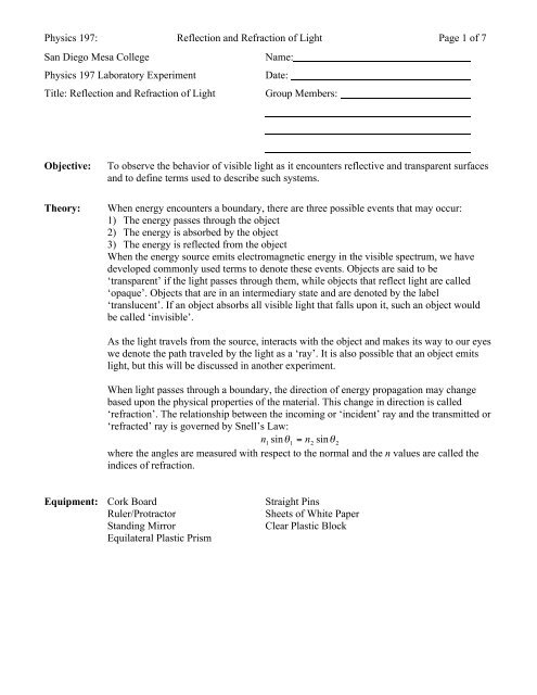
<strong>Physics</strong> <strong>197</strong>: Reflection and Refraction of Light Page 1 of 7<br />
<strong>San</strong> <strong>Diego</strong> <strong>Mesa</strong> <strong>College</strong><br />
<strong>Physics</strong> <strong>197</strong> Laboratory Experiment<br />
Title: Reflection and Refraction of Light<br />
Name:<br />
Date:<br />
Group Members:<br />
Objective:<br />
Theory:<br />
To observe the behavior of visible light as it encounters reflective and transparent surfaces<br />
and to define terms used to describe such systems.<br />
When energy encounters a boundary, there are three possible events that may occur:<br />
1) The energy passes through the object<br />
2) The energy is absorbed by the object<br />
3) The energy is reflected from the object<br />
When the energy source emits electromagnetic energy in the visible spectrum, we have<br />
developed commonly used terms to denote these events. Objects are said to be<br />
‘transparent’ if the light passes through them, while objects that reflect light are called<br />
‘opaque’. Objects that are in an intermediary state and are denoted by the label<br />
‘translucent’. If an object absorbs all visible light that falls upon it, such an object would<br />
be called ‘invisible’.<br />
As the light travels from the source, interacts with the object and makes its way to our eyes<br />
we denote the path traveled by the light as a ‘ray’. It is also possible that an object emits<br />
light, but this will be discussed in another experiment.<br />
When light passes through a boundary, the direction of energy propagation may change<br />
based upon the physical properties of the material. This change in direction is called<br />
‘refraction’. The relationship between the incoming or ‘incident’ ray and the transmitted or<br />
‘refracted’ ray is governed by Snell’s Law:<br />
n<br />
1<br />
sinθ1<br />
= n2<br />
sinθ<br />
2<br />
where the angles are measured with respect to the normal and the n values are called the<br />
indices of refraction.<br />
Equipment: Cork Board<br />
Ruler/Protractor<br />
Standing Mirror<br />
Equilateral Plastic Prism<br />
Straight Pins<br />
Sheets of White Paper<br />
Clear Plastic Block
<strong>Physics</strong> <strong>197</strong>: Reflection and Refraction of Light Page 2 of 7<br />
Part I: Ray Tracing<br />
Setup and Procedure:<br />
1) Attach a piece of clean white paper to the cork board using push pins at each corner.<br />
2) Insert a straight pin (Pin 1) vertically into the middle of the paper. Insert another<br />
straight pin (Pin 2) vertically into the paper about 8cm in front of Pin 1. Write a small<br />
number 1 and 2 near the base of the appropriate pin.<br />
3) Lower your head to the level of the table, close one eye and look at Pin 2. Move your<br />
head until Pin 2 obscures Pin 1.<br />
4) Remove both pins, and use the ruler/protractor to draw a straight line segment that<br />
connects the two pinholes and extends a few cm beyond the hole made by Pin 2.<br />
5) Replace the pins in their respective holes and look down the line segment that you just<br />
drew. This line segment is called a ‘ray trace’. You will label this ‘Ray Trace 1’<br />
Can you now see Pin 1?<br />
Can you conclude that the light reflected from Pin 1 travels in a straight line?<br />
You will now use the technique of making one pin ‘disappear’ behind the other to establish<br />
some more properties of reflected light.<br />
6) Place a third pin (Pin 3) along the ray trace you created in 5) but a few cm closer to you<br />
than Pin 2 and look down the ray trace. You should only be able to see Pin 3<br />
7) Move Pin 2 about 1 cm to the right or left of Ray Trace 1 and adjust your viewing<br />
position until Pin 2 obscures Pin 1.<br />
8) Remove Pin 3 from the paper and place it in a new position such that it obscures Pins 1<br />
and 2.<br />
9) Remove Pins 2 and 3 and draw a ray trace connecting the pinholes.<br />
10) Repeat steps 7)-9) until you have a total of four ray traces as shown below.
<strong>Physics</strong> <strong>197</strong>: Reflection and Refraction of Light Page 3 of 7<br />
11) Extend Ray Traces 1-4 towards the location of Pin 1.<br />
What, if anything can you conclude about the light that reflects off Pin 1?<br />
Part II: Reflection of Light<br />
Setup and Procedure<br />
1) Secure a new sheet of paper to the cork board and place the mirror near the middle of<br />
the paper.<br />
2) Draw a line bisecting the paper that marks the back edge of the mirror.<br />
3) Place a pin 8 cm in front of and 2 cm to the right of the edge of the mirror, as indicated<br />
in the diagram. This is Pin 1, also called the Object Pin(OP1).<br />
4) Lower your head to table level and adjust your position until you can see the image of<br />
the OP in the mirror.<br />
Where does this image appear to be located?
<strong>Physics</strong> <strong>197</strong>: Reflection and Refraction of Light Page 4 of 7<br />
5) Take a second pin (OP2) and place it about 4 cm in front of the mirror and toward the<br />
opposite side the mirror as the location of OP1.<br />
6) Adjust your gaze so that OP2 obscures the image of OP1. Place another pin (OP3) so<br />
that it blocks both OP2 and the image of OP1.<br />
7) Remove all three pins and the mirror.<br />
8) Draw a ray trace between the positions of OP2 and OP3 and extend it past the line<br />
denoting the position of the rear of the mirror to within a few cm of the rear of the<br />
paper.<br />
9) Locate the intersection of this ray trace and the line locating the mirror, Extend a line<br />
from this point through the location of OP1<br />
You have now just demonstrated that the light ray originating from OP1 traveled in a<br />
straight line to the mirror and then from the mirror to your eye in its location near OP3.<br />
Why was the rear of the mirror chosen as the intersection point?<br />
10) Now draw a line segment that originates at the intersection of the rays and the line<br />
marking the back of the mirror. The line segment should be drawn perpendicular to the<br />
mirror line, extending towards the front of the paper.<br />
11) Use the protractor to measure the angle formed by the perpendicular segment and the<br />
ray trace from OP1 and record it below:<br />
Angle of Incidence:<br />
12) Now use the protractor to measure the angle formed by the perpendicular segment and<br />
the ray trace from OP2 and OP3. Record it below and comment on the relationship.<br />
Angle of Reflection:<br />
13) Replace the mirror and OP1 to their initial positions, Move OP2 to a new location and<br />
repeat the procedure of ray tracing four more times, so you have a total of five lines<br />
crossing the line of the mirror.<br />
Do the lines seem to have a common point of intersection? Where is this point in relation<br />
to the apparent location of the image of OP1 addressed in step 4)?<br />
So, to your eyes, it appears as though all the light rays that describe OP1 originated at a<br />
point behind the plane of the mirror. This point is called the Image Point (IP).<br />
14) Measure the perpendicular distance from the back of the mirror to OP1 and record it<br />
below. Repeat the process for IP1, then place a pin to mark IP1.<br />
X OP1 = X IP1 =
<strong>Physics</strong> <strong>197</strong>: Reflection and Refraction of Light Page 5 of 7<br />
15) Now position your eye so you can simultaneously see the bottom of the image of OP1<br />
and the top of the pin placed at IP1.<br />
Describe what you see. Can you see a difference in size between the image of the object<br />
and the pin at the image position? Slowly lift the mirror and comment on your observation.<br />
16) Now place a pin directly in front of the mirror and adjacent to the image of OP1 so you<br />
can compare the sizes of the image of OP1 and an actual pin.<br />
Comment on the sizes of the image and the comparison pin.<br />
So, a plane mirror ‘creates’ an image of an object. The rays diverging from the comparison<br />
pin and the image of OP1 both carry information about the object with which they<br />
interacted. Even though our eyes intercept only a small portion of these rays we are still<br />
able to judge many attributes of the object’s surface. Since the geometry of the plane<br />
mirror does not change the spatial relationships of the rays, the image of the object appears<br />
to be identical in size and location to the object itself. To repeat – there is no difference in<br />
the information carried by the rays before and after interaction with the surface of the<br />
mirror. This is similar in many ways to the elastic collision of an object with a massive<br />
surface, where the direction of the momentum is reversed, but the magnitude is unchanged.<br />
Part III: Refraction of Light<br />
Setup and Procedure:
<strong>Physics</strong> <strong>197</strong>: Reflection and Refraction of Light Page 6 of 7<br />
M<br />
I<br />
φ<br />
A<br />
B<br />
P 2 P 1<br />
θ<br />
D<br />
C<br />
P 3<br />
O<br />
P 4<br />
M’<br />
1) Take a clean sheet of paper and fasten it to the cork board. Draw a line (MM’)<br />
bisecting the paper. Place the plastic block upon the paper with the long edge of the<br />
block in the same direction as the long side of the paper with about _ of the length of<br />
the block on one side of the line. Trace the outline of the block and label the four<br />
corners as A,B,C,D. Remove the block.<br />
2) Where the line AB intersects with line MM’, label that as point I. Draw a line from<br />
point I towards the near edge of the paper that makes a 45 degree angle (φ) with MM’.<br />
3) Place a pair of pins at distances of 1” and 2” from point I. Label these points as P 1 and<br />
P 2, respectively.<br />
4) Carefully replace the block on the paper, and look through side CD until you find a<br />
position where P 2 obscures P 1 .<br />
5) Maintain this position and insert a pin in location P 3 such that it obscures both P 1 and<br />
P 2 . Then insert P 4 in such a way that it is closer to the edge of your paper than P 3 and it<br />
obscures all the other pins.<br />
6) Remove the block and pins P 3 and P 4 . Draw a line segment extending from P 4 through<br />
P 3 and towards line MM’. Where this segment crosses line CD, mark the point as O.<br />
7) Draw a line segment from point O to point I.<br />
8) Starting at point O, draw a line segment perpendicular to line CD, which should also be<br />
parallel to MM’. Now determine the angle θ made by the refracted ray inside the<br />
block.<br />
9) Repeat steps 2) through 8) for φ = 25 degrees and fill in the data table below using<br />
Snell’s Law to calculate the index of refraction of the block.
<strong>Physics</strong> <strong>197</strong>: Reflection and Refraction of Light Page 7 of 7<br />
Data:<br />
φ θ n block<br />
45<br />
Show all calculations in the space below:<br />
25<br />
Analysis:<br />
Look up the standard index of refraction of Lucite plastic. Calculate the percent error<br />
between the standard accepted value for Lucite and the average index of refraction<br />
obtained through your experiment.<br />
naccepted<br />
− nexp<br />
erimental<br />
% error = * 100 =<br />
n<br />
accepted<br />
Conclusion: Briefly discuss the physics involved in the experiment, summarize the data, address potential<br />
sources of error and methods to reduce or eliminate them, and state whether or not the<br />
experimental results validate the theory.