UCL-200 Ultrasonic Continuous Level Transmitter - Pressure Switch ...
UCL-200 Ultrasonic Continuous Level Transmitter - Pressure Switch ...
UCL-200 Ultrasonic Continuous Level Transmitter - Pressure Switch ...

You also want an ePaper? Increase the reach of your titles
YUMPU automatically turns print PDFs into web optimized ePapers that Google loves.
To return to factory settings, remove power to the transducer for at least 10 seconds, then reapply power while<br />
pressing the "Set" and "Menu" buttons.<br />
To change the unit of measurement from inches to centimeters, remove power to the transmitter for at least 10<br />
seconds, then reapply power while simultaneously pressing the "s" and "Set" buttons.<br />
Return Policy<br />
Returns are accepted on stock items up to 30 days from date of order. You must contact our Returns Department for a<br />
Return Authorization (RA) number. Return the goods - freight prepaid - in the original container and include original<br />
packing slip. C. O. D. returns are not accepted. Gems reserves the right to apply restocking charges.<br />
Tel: 860-793-4357<br />
Fax: 860-793-4563<br />
Factory Settings<br />
EC4 288"<br />
EC20 8"<br />
SAF1/2/3 Saf1<br />
Fast/Slow Fast<br />
• Gems products must be maintained and installed in strict accordance<br />
with the National Electrical Code and the applicable Gems<br />
product instruction Bulletin that covers installation, operation and<br />
proper maintenance. Failure to observe this information may result<br />
in serious injury or damages.<br />
• The supply voltage to the sensor should not exceed 36 VDC, Max.<br />
• Please adhere to the pressure and temperature limitations shown<br />
throughout this catalog for our level and flow sensors. These<br />
limitations must not be exceeded. These pressures and temperatures<br />
take into consideration possible system surge pressures/<br />
temperatures and their frequencies.<br />
• Selection of materials for compatibility with the media is critical to<br />
the life and operation of Gems products. Take care in the proper<br />
selection of materials of construction, testing is required.<br />
Important Points:<br />
Gems Sensors Inc.<br />
One Cowles Road<br />
Plainville, CT 06062-1198<br />
Toll-Free: 1-800-378-1600<br />
HSET 5"<br />
LSET 288"<br />
RLAY N/A<br />
TANK 288"<br />
ALIN Off<br />
• Avoid overtightening when mounting<br />
• Life expectancy of switch contacts varies with application. Contact<br />
Gems if life cycle testing is required.<br />
• Ambient temperature changes do affect switch set points, since the<br />
gravity of a liquid can vary with temperature.<br />
• Our sensors have been designed to resist shock and vibration.<br />
However, shock and vibration should be minimized.<br />
• Electrical entries and mounting points in an enclosed tank may<br />
require liquid/vapor sealing.<br />
• Our sensors must not be field-repaired.<br />
• Physical damage sustained by product may render it unserviceable.<br />
Precautions are taken to ensure safe arrival of all shipments. Should you receive goods damaged in transport, you must file a claim with<br />
the carrier within 90 days or the claim is waived. Gems Sensors Inc. shall not be liable for any damage in case of late delivery or lost<br />
shipments.<br />
Warranty<br />
Gems Sensors Inc., the seller, warrants its products to be free from defects in material and workmanship in normal use and service for a<br />
period of one year from date of shipment. Gems reserves the right and option to refund the purchase price in lieu of repair or replacement<br />
upon evaluation of the returned original part. Modification, misuse, attempted repair by others, improper installation or operation shall<br />
render this guarantee null and void. Gems Sensors Inc. makes no warranty of merchantability or fitness for a part or purpose.<br />
Limits of Liability<br />
In no circumstances shall Gems Sensors Inc. be liable for special, consequential or exemplary damages of any kind or character, including<br />
contract, tort, and strict liability in tort and contract.<br />
Equipment sold by Gems Sensors Inc. not intended for use in a nuclear installation, nor shall it be used as a “Basic Component” as same<br />
as defined under Part 21, Title 10 of the Code of Federal Regulations. In the event of such use, you agree to indemnify and hold us<br />
harmless from any and all subsequent liabilities and responsibilities which might arise in connection with such use.<br />
Instruction Bulletin No. 197458<br />
Rev. A<br />
<strong>UCL</strong>-<strong>200</strong><br />
<strong>Ultrasonic</strong> <strong>Continuous</strong> <strong>Level</strong> <strong>Transmitter</strong><br />
Principle of Operation<br />
An ultrasonic sound wave is transmitted from the base of the transducer. This sound wave is reflected off the<br />
process medium and returned to the transducer. The sensor's electronics calculate the travel time the sound wave<br />
requires and determines the distance between the transducer and the medium.<br />
Specifications<br />
Operating Temperature<br />
Operating <strong>Pressure</strong><br />
Input Voltage<br />
Output<br />
Range<br />
Accuracy<br />
Resolution<br />
Beam Width<br />
Enclosure Rating<br />
Enclosure Material<br />
Transducer Material<br />
Conduit connection<br />
Mounting<br />
Relay<br />
Max. Series Resistance (Ohms)<br />
2,000<br />
1,500<br />
1,000<br />
500<br />
Mounting<br />
4 or 20 mA<br />
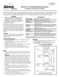
Sensor Electrical Loading Limits<br />
Unacceptable<br />
Range<br />
Acceptable<br />
Range<br />
0<br />
12 18 24 30 36<br />
Supply Voltage (VDC)<br />
-40°F to 140°F<br />
30 psi @ 25°C (See chart below)<br />
14 to 36 VDC<br />
4-20 mA (3-Wire sourcing)<br />
6" to 294"<br />
± 0.25% of span in air<br />
0.125" (3 mm)<br />
8° Conical<br />
NEMA 4X (IP65)<br />
Polypropylene<br />
PVDF<br />
1/2" NPT<br />
2" NPT<br />
SPDT, 250 VAC, 10 A, 1/2 Hp<br />
Maximum Temperature/Voltage Derating<br />
<strong>Continuous</strong> 20 mA Curve<br />
100<br />
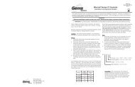
The unit must be mounted vertically above the process medium (liquid) to be<br />
measured.<br />
1. The maximum measurable distance is 294" (24.5 Ft.)<br />
2. There is a "dead zone" less than 6" from the end of the transducer.<br />
The transducer cannot meaure less than 6" from its tip. This dead<br />
zone can also be set to a distance greater than 6".<br />
3. The transducer's ultrasonic signal is cone-shaped with an 8° beam<br />
angle. Care must be taken to ensure that there are no obstructions<br />
to the beam (wall of tank, ladder, etc.). See diagrams.<br />
Acceptable<br />
Range<br />
Important Notes<br />
1. Avoid interference with the beam from the side of the tank and obstructions<br />
in the tank.<br />
2. Do not install the transducer at an angle.<br />
3. The transducer will not operate in a vacuum.<br />
4. The transducer will not operate properly with the presence of vapors or foam.<br />
5. Do not thread more than 1-2 turns past hand-tight.<br />
Ambient Sensor Temperature (°C)<br />
80<br />
60<br />
40<br />
20<br />
Unacceptable<br />
Range<br />
Dimensions<br />
2"<br />
NPT<br />
3.6"<br />
(91 mm)<br />
4.9"<br />
(124 mm)<br />
6.3"<br />
(163 mm)<br />
Temperature/<strong>Pressure</strong> Derating<br />
Acceptable<br />
Range<br />
Unacceptable<br />
Range<br />
0<br />
00<br />
12 16 20 24 28 32 36 -40 -20 00 20 40 60 80<br />
Operating Voltage (VDC)<br />
Temperature (°C)<br />
Depth Range<br />
(In Feet)<br />
1<br />
2<br />
4<br />
6<br />
8<br />
10<br />
12<br />
14<br />
16<br />
18<br />
20<br />
22<br />
24<br />
Operating <strong>Pressure</strong> (psi)<br />
35<br />
30<br />
25<br />
20<br />
15<br />
10<br />
05<br />
Beam Radius<br />
(In Inches)<br />
1.2<br />
2.1<br />
3.7<br />
5.4<br />
7.1<br />
8.8<br />
10.4<br />
12.1<br />
13.8<br />
15.5<br />
17.2<br />
18.8<br />
20.5<br />
D<br />
R
E. Using the ALIN Mode (default is OFF)<br />
The ALIN mode is used when mounting or troubleshooting the transmitter. When the transmitter is in the<br />
ALIN mode, the signal return strength will be displayed in dB. This mode can be used when mounting the<br />
transmitter to determine optimal alignment. It can also be used to check signal strength when<br />
troubleshooting the transmitter.<br />
1. Hold the “MENU" key until “ALIN” appears in the display<br />
2. Continue to hold “MENU” until “OFF” appears in the display<br />
3. Release the “MENU” key and hold the “SET” key to switch from “OFF” to “ON”<br />
4. Release the “SET” key and the transmitter is now in the ALIN mode.<br />
5. To exit the ALIN mode, repeat Steps 1 through 4 to switch from “ON” to “OFF”. The ALIN mode<br />
must be turned off in order for the transmitter to start measuring level again and it will not turn off by<br />
itself like the other programming modes.<br />
F. Setting the Relay (RLAY) (HSET & LSET)<br />
This mode is used to set the high and low points of relay activation.<br />
The relay will energize when the display value is greater than the<br />
LSET value and de-energize when the display value drops below<br />
the HSET value.<br />
1. Hold the "MENU" key until HSET or LSET appears in the display<br />
2. Release the "MENU" key and wait for a value to appear in the display<br />
3. Press the UP (s) or DOWN (t) arrow keys to change the display to<br />
the desired value<br />
4. Press the SET key to lock in the setting<br />
5. Perform these steps for both HSET and LSET<br />
G. Setting the Tank Depth (TANK)<br />
1. Hold the "MENU" key until TANK appears in the display<br />
2. Continue holding "MENU" key until a value appears in the display, which will be the current tank setting<br />
3. Press the UP (s) or DOWN (t) arrow keys to change the display to the desired value (max tank height)<br />
4. Press "SET" key to lock in setting<br />
For High <strong>Level</strong> Alarm:<br />
(COM) BLUE<br />
(NC) GREEN<br />
ALARM<br />
SUPPLY<br />
Set HSET and LSET to the same value (alarm level)<br />
For Low <strong>Level</strong> Alarm:<br />
(COM) BLUE<br />
(NO) YELLOW<br />
ALARM<br />
SUPPLY<br />
Set HSET and LSET to the same value (alarm level)<br />
LSET<br />
RELAY OFF<br />
HSET<br />
RELAY ON<br />
Helpful Hints<br />
EC20<br />
EC4<br />
For Auto Fill (Pump-Up): (COM) BLUE<br />
(NO) YELLOW<br />
PUMP<br />
SUPPLY<br />
Set HSET to high level value (pump off) and LSET to low level value<br />
(pump on)<br />
For Auto Empty (Pump-Down): (COM) BLUE<br />
(NC) GREEN<br />
PUMP<br />
SUPPLY<br />
Set HSET to high level value (pump on) and LSET to low level value<br />
(pump off)<br />
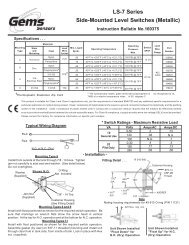
Wiring<br />
Programming<br />
Gems Sensors <strong>UCL</strong>-<strong>200</strong><br />
<strong>Ultrasonic</strong><br />
<strong>Level</strong> <strong>Transmitter</strong><br />
RELAY<br />
MENU<br />
SET<br />
←9" Cable (228mm) →<br />
PVC-Jacketed, Shielded, 20 AWG<br />
(-) Black<br />
(+) Red<br />
Signal White<br />
COM blue<br />
NC Green<br />
NO Yellow<br />
Only the EC4 and EC20 values need to be set for operation. Setting the MAXR and MINR values is highly<br />
recommended for more accurate operation. The ALIN mode is only used to determine signal strength, which<br />
may be needed when mounting or for troubleshooting the transmitter. RLAY, HSET, and LSET are used to<br />
program the relay operation. Holding the "MENU" key will scroll through the modes in following order: LEVEL,<br />
EC4, EC20, RLAY, HSET, LSET, SAF 1/2/3, FAST/SL, ALIN, OFF/O TANK.<br />
A. Setting EC4 Value (This is the 4 mA setting which equates to the lowest measure point in the tank)<br />
1. Hold “MENU” key until “EC4” appears in the display and then release<br />
2. Wait until a value appears which will be the current measured level<br />
3. Press the up or down arrow keys once to display the current EC4 value<br />
4. Press the up or down arrow keys to change the EC4 value to your desired setting (the longer you hold<br />
these buttons, the faster the value will change). 216" is the maximum measurable value.<br />
5. Press “SET” key to lock in this value<br />
6. The display will show “ENTER” to indicate the value is set and then “LEVEL” as it returns to measuring<br />
the level.<br />
B. Setting the EC20 Value (This is the 20 mA setting which will be the highest measure point in the<br />
tank)<br />
1. Hold “MENU” key until “EC20” appears in the display and then release<br />
2. Wait until a value appears which will be the current measured level<br />
3. Press the up or down arrow keys once to display the current EC20 value<br />
4. Press the up or down arrow keys to change the EC20 value to your desired setting (6" is the absolute<br />
min. value, but 8" is the recommended min.)<br />
5. Press “SET” key to lock in this value<br />
C. Setting the Fail-Safe Mode (default setting is SAF1)<br />
SAF1 = The output will go to 22 mA if the ultrasonic signal is lost<br />
SAF2 = The output will go to 4 mA if the signal is lost<br />
SAF3 = The output will hold the current (last measured value) if the signal is lost<br />
1. Hold the “MENU” key until “SAFI”, SAF2" or “SAF3” appears in the display<br />
2. Release the “MENU” key and hold the “SET” key to toggle from SAFI to SAF2 to SAF3<br />
3. When the desired mode is reached, release the “SET” key to lock in that setting<br />
⎬<br />
⎬<br />
4-20mA<br />
D. Setting the FAST/SLOW Mode (default is FAST)<br />
This determines the averaging rate at which the signal is processed. The FAST mode is typical and will have<br />
2 signals per second and update once a second. The SLOW mode is generally used in turbulent applications.<br />
The signal returns are averaged every 10 seconds in the SLOW mode.<br />
1. Hold the “MENU” key until “FAST” or “SLOW" appears in the display<br />
2. Release the “MENU” key and hold the “SET” key to switch between “FAST” and “SLOW’ modes<br />
3. Release the “SET” key when the desired mode is displayed to lock in the setting.<br />
Relay