

AVX Piezoelectric Acoustic Generators Catalog
AVX Piezoelectric Acoustic Generators Catalog
AVX Piezoelectric Acoustic Generators Catalog

Create successful ePaper yourself
Turn your PDF publications into a flip-book with our unique Google optimized e-Paper software.
<strong>Piezoelectric</strong> <strong>Acoustic</strong> <strong>Generators</strong><br />
Suggestions for Handling<br />
In order to maximize the quality of piezoelectric elements,<br />
it is necessary that proper handling procedures be used.<br />
Do not operate or store for a long time under conditions of<br />
high temperature and high humidity.<br />
• <strong>Piezoelectric</strong> characteristics may degrade when kept at<br />
more than 80° C for a long time.<br />
• The electrodes may be shorted if a drop of water falls<br />
onto the silver electrode area of the transducer.<br />
Keep soldering time to a minimum.<br />
• Soldering operation must be less than 320°C and<br />
completed within 1.5 seconds.<br />
• 2% silver solder for silver electrodes must be used to<br />
prevent leaching.<br />
• <strong>Piezoelectric</strong> acoustic elements are supplied with leads<br />
for our customers' convenience. The specifications are<br />
as follows:<br />
1) Standard lead specification AWG#28 and AWG#32<br />
(7 strand copper wires covered with red color vinyl<br />
insulation)<br />
2) Standard length (mm) 50, 75, 100, 125, 150<br />
Remember that the 3-terminal type is a part of the oscillation<br />
circuit.<br />
• Do not place a cover in front of the buzzer, if possible.<br />
• When assembling, do not deform or bend the transducer<br />
fixture. Deformation of the transducer changes<br />
the oscillation condition.<br />
NOTE: Wherever possible, the piezo devices should be<br />
capacitive coupled to avoid permanent DC bias and possible<br />
long term damage.<br />
Drive Circuits<br />
Because the impedance of the piezoelectric buzzer (2-<br />
terminal type) is capacitive, the drive circuit can be designed<br />
utilizing the transducer as a capacitor.<br />
Drive circuits are classified into two types. One type is the<br />
amplification type which amplifies and supplies input signal<br />
(from IC, etc.) to the transducer. The other is the oscillation<br />
type, in which the transducer constitutes a part of the circuit<br />
together with other active elements.<br />
Typical circuit types are as follows:<br />
Table I<br />
Transducer Drive Circuit<br />
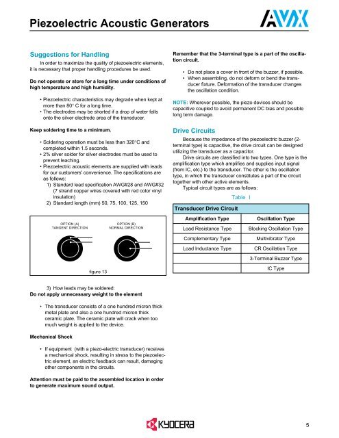
OPTION (A)<br />
TANGENT DIRECTION<br />
OPTION (B)<br />
NORMAL DIRECTION<br />
Amplification Type<br />
Load Resistance Type<br />
Oscillation Type<br />
Blocking Oscillation Type<br />
Complementary Type<br />
Multivibrator Type<br />
Load Inductance Type<br />
CR Oscillation Type<br />
3-Terminal Buzzer Type<br />
figure 13<br />
IC Type<br />
3) How leads may be soldered:<br />
Do not apply unnecessary weight to the element<br />
• The transducer consists of a one hundred micron thick<br />
metal plate and also a one hundred micron thick<br />
ceramic plate. The ceramic plate will crack when too<br />
much weight is applied to the device.<br />
Mechanical Shock<br />
• If equipment (with a piezo-electric transducer) receives<br />
a mechanical shock, resulting in stress to the piezoelectric<br />
element, an electric feedback can result, damaging<br />
other components in the circuits.<br />
Attention must be paid to the assembled location in order<br />
to generate maximum sound output.<br />
5


