Repco Pump Booster Packages - RE Prescott Company
Repco Pump Booster Packages - RE Prescott Company
Repco Pump Booster Packages - RE Prescott Company

You also want an ePaper? Increase the reach of your titles
YUMPU automatically turns print PDFs into web optimized ePapers that Google loves.
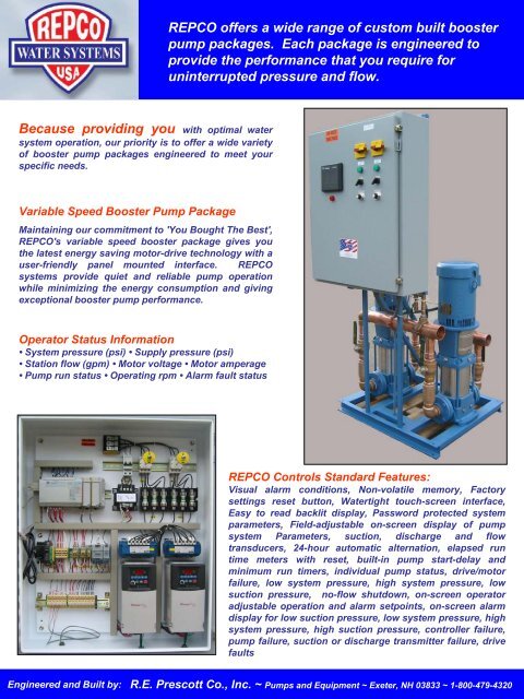
<strong>RE</strong>PCO offers a wide range of custom built booster<br />
pump packages. Each package is engineered to<br />
provide the performance that you require for<br />
uninterrupted pressure and flow.<br />
Because providing you with optimal water<br />
system operation, our priority is to offer a wide variety<br />
of booster pump packages engineered to meet your<br />
specific needs.<br />
Variable Speed <strong>Booster</strong> <strong>Pump</strong> Package<br />
Maintaining our commitment to 'You Bought The Best',<br />
<strong>RE</strong>PCO's variable speed booster package gives you<br />
the latest energy saving motor-drive technology with a<br />
user-friendly panel mounted interface. <strong>RE</strong>PCO<br />
systems provide quiet and reliable pump operation<br />
while minimizing the energy consumption and giving<br />
exceptional booster pump performance.<br />
Operator Status Information<br />
• System pressure (psi) • Supply pressure (psi)<br />
• Station flow (gpm) • Motor voltage • Motor amperage<br />
• <strong>Pump</strong> run status • Operating rpm • Alarm fault status<br />
<strong>RE</strong>PCO Controls Standard Features:<br />
Visual alarm conditions, Non-volatile memory, Factory<br />
settings reset button, Watertight touch-screen interface,<br />
Easy to read backlit display, Password protected system<br />
parameters, Field-adjustable on-screen display of pump<br />
system Parameters, suction, discharge and flow<br />
transducers, 24-hour automatic alternation, elapsed run<br />
time meters with reset, built-in pump start-delay and<br />
minimum run timers, individual pump status, drive/motor<br />
failure, low system pressure, high system pressure, low<br />
suction pressure, no-flow shutdown, on-screen operator<br />
adjustable operation and alarm setpoints, on-screen alarm<br />
display for low suction pressure, low system pressure, high<br />
system pressure, high suction pressure, controller failure,<br />
pump failure, suction or discharge transmitter failure, drive<br />
faults<br />
Engineered and Built by: R.E. <strong>Prescott</strong> Co., Inc. ~ <strong>Pump</strong>s and Equipment ~ Exeter, NH 03833 ~ 1-800-479-4320
<strong>RE</strong>PCO PUMPS and CONTROLS<br />
Water <strong>Booster</strong> System Specifications<br />
SECTION 1. - WATER BOOSTER SYSTEM<br />
CONTROLS<br />
.01 SCOPE: The scope of this section of the<br />
specifications includes the furnishing of a <strong>RE</strong>PCO<br />
CONTROLS panel as described herein, as<br />
manufactured by R.E. <strong>Prescott</strong> Co., Inc. The Control<br />
Panel is to provide the control functions of a water<br />
supply system consisting of 2 booster pumps, 1 suction<br />
transmitter and 1 pressure transmitter.<br />
.02 ENCLOSU<strong>RE</strong>: The control panel will be housed<br />
in a lockable NEMA 12 enclosure with stainless steel<br />
hardware. Panel enclosure fabricated out of 14 gauge<br />
steel. Exterior coating is ANSI-61 grey. All seams are<br />
continuously welded.<br />
.03 BACK PANEL: Interior control devices are to be<br />
mounted on a steel control panel backplate. Backplate is fabricated out of 12 gauge<br />
steel. Finish is white polyester paint.<br />
• Manual lockable disconnects for each pump<br />
• Motor Starters, VFD, AB, PowerFlex Series<br />
• Power fuse blocks and fuses for each pump<br />
• Control Circuit Breaker<br />
• Control Transformer<br />
• Programmable Logic Controller, Allen Bradley, 1500 series<br />
• Control Relays<br />
• Power Supplies<br />
• Remote Control Devices<br />
• Control Fuses and Holders<br />
.04 EXTERNAL CONTROL PANEL DOOR: A continuous hinge is provided on<br />
the long side. The door can be removed by pulling the hinge pin. The control panel<br />
door will have the following components wired and mounted:<br />
• Individual Motor Disconnects with Lockout Protection<br />
• <strong>Pump</strong> Run Indication<br />
• Individual Hand-Off-Automatic Selector Switches<br />
• Manual speed potentiometers for each pump<br />
• Pilot Light Indicators<br />
• General Alarm Indication<br />
• Human-Machine interface panel, Allen Bradley, PV-550<br />
.05 CONTROL DEVICES: Industrial grade pressure transmitters are included for
the linear measurement of the station suction pressure and station discharge pressure.<br />
The transmitters are 4-20mA, 2 wire transducers with a 0.5% accuracy. The power<br />
supply is 12-30 VDC. Pressure transmitters are 316 stainless steel wetted parts and<br />
optional flow transmitters as manufactured by ONICON model F1111.<br />
.05 FUNCTIONS: The control panel provides system control functions. Motor<br />
VFDs, HOA switches, potentiometers, and run lights are incorporated in the controls.<br />
The control panel is to provide the following operating functions:<br />
1. The control panel will provide output signals for 2 booster pumps to operate<br />
in a lead/lag manner with alternation after each pumping cycle or on a 24 hour<br />
basis. Control of the booster pumps is based on inputs from the pressure<br />
transmitter for off, lead on, lag on and alarms. Low suction protection is<br />
provided for the booster pumps in automatic mode based on inputs from<br />
suction transmitter.<br />
2. The control panel will provide a startup time delay on each pump. These time<br />
delays are to provide the staging on of the pumps following a loss of electrical<br />
power.<br />
3. The transmitters will operate on a sensing voltage of 24 VAC through a<br />
regulated power supply.<br />
4. The control panel is to be line powered by 208-230/480 VAC, single or three<br />
Phase, 60 Hz with a control transformer for 115 VAC control power.<br />
5. An uninterruptible power supply, UPS is also included.<br />
.06 DOCUMENTATION: Documentation provided for the control panel to include<br />
the following information:<br />
1. Installation and operating instructions.<br />
2. Description of control panel functions.<br />
3. Replacement Parts list.<br />
4. Wiring diagrams<br />
SECTION 2. - WATER BOOSTER PUMPS<br />
.01 GENERAL ASSEMBLY<br />
1. <strong>Booster</strong> system is factory assembled on a structural steel skid.<br />
2. An optional Cycle Tank is shipped loose and field installed next to the<br />
package.<br />
3. All pumps, piping, fittings and control panel are pre-wired and pre-piped for<br />
single point connections.<br />
4. Suction and discharge headers are constructed of non-ferrous material in<br />
accordance with AWWA standards for potable water.<br />
5. Each pump is equipped with flange union connections for ease of service.<br />
6. Each pump has a discharge check valve and ball valve isolation valves.<br />
7. Factory finished in enamel blue paint.<br />
.02 VERTICLE PUMPS<br />
1. System includes two multi-stage, vertical centrifugal pumps with ANSI<br />
flanges.<br />
2. <strong>Pump</strong>s are constructed of stainless steel as supplied by the pump
manufacturer.<br />
3. <strong>Pump</strong>s are equipped with mechanical shaft seals<br />
4. <strong>Pump</strong> motors will be of the horsepower required to provide system operation<br />
specifications and be 208-230/480 Volt, 60 Hz and 3 Phase.<br />
03. CHECK and BALL VALVES<br />
1. Each pump is fitted with silent check valves as manufactured by Flomatic<br />
Valve Corp.<br />
2. Each pump is fitted with quarter turn ball valves as manufactured by A.Y.<br />
McDonald Mfg.<br />
.04 THERMAL PURGE (Optional)<br />
1. A 2 GPM recirculation line with an electric solenoid valve that will<br />
recirculate water to the suction header during times of no flow when the<br />
pumps are running is available.<br />
2. During times of system flow greater than 3 USGPM the solenoid is off<br />
preventing recirculation.<br />
.05 HYDRO-PNEUMATIC TANK (Optional)<br />
1. 185 gallon hydro-pneumatic tank is manufactured by Flexcon Industries<br />
2. Tank is manufactured out of carbon steel.<br />
3. A replaceable bladder is standard.<br />
4. Tank is stamped with the ASME code and rated for 200 PSI.<br />
5. Tank is shipped loose for field installation by others.<br />
.06 MANUFACTU<strong>RE</strong>RS:<br />
This is to be a <strong>RE</strong>PCO PUMPS and CONTROLS Water <strong>Booster</strong> System by:<br />
R.E. <strong>Prescott</strong> Co., Inc.; 10 Railroad Ave.; Exeter, NH 03833; 603-772-4321<br />
Est. 1954