Fleck Model 9000/9100/9500 - Pentair Residential Filtration
Fleck Model 9000/9100/9500 - Pentair Residential Filtration
Fleck Model 9000/9100/9500 - Pentair Residential Filtration

Create successful ePaper yourself
Turn your PDF publications into a flip-book with our unique Google optimized e-Paper software.
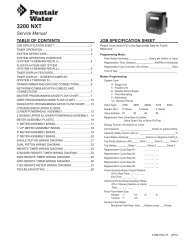
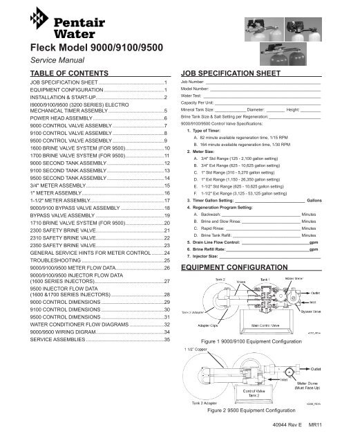
<strong>Fleck</strong> <strong>Model</strong> <strong>9000</strong>/<strong>9100</strong>/<strong>9500</strong><br />
Service Manual<br />
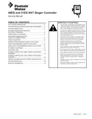
TABLE OF CONTENTS<br />
JOB SPECIFICATION SHEET................................................1<br />
EQUIPMENT CONFIGURATION............................................1<br />
INSTALLATION & START-UP.................................................2<br />
I<strong>9000</strong>/<strong>9100</strong>/<strong>9500</strong> (3200 SERIES) ELECTRO<br />
MECHANICAL TIMER ASSEMBLY.........................................5<br />
POWER HEAD ASSEMBLY....................................................6<br />
<strong>9000</strong> CONTROL VALVE ASSEMBLY......................................7<br />
<strong>9100</strong> CONTROL VALVE ASSEMBLY......................................8<br />
<strong>9500</strong> CONTROL VALVE ASSEMBLY......................................9<br />
1600 BRINE VALVE SYSTEM (FOR <strong>9500</strong>)............................10<br />
1700 BRINE VALVE SYSTEM (FOR <strong>9500</strong>)............................11<br />
<strong>9000</strong> SECOND TANK ASSEMBLY..........................................12<br />
<strong>9100</strong> SECOND TANK ASSEMBLY..........................................13<br />
<strong>9500</strong> SECOND TANK ASSEMBLY..........................................14<br />
3/4" METER ASSEMBLY........................................................15<br />
1" METER ASSEMBLY...........................................................16<br />
1-1/2" METER ASSEMBLY.....................................................17<br />
<strong>9000</strong>/<strong>9100</strong> BYPASS VALVE ASSEMBLY................................18<br />
BYPASS VALVE ASSEMBLY..................................................19<br />
1710 BRINE VALVE SYSTEM (FOR <strong>9500</strong>)............................20<br />
2300 SAFETY BRINE VALVE.................................................21<br />
2310 SAFETY BRINE VALVE.................................................22<br />
2350 SAFETY BRINE VALVE.................................................23<br />
GENERAL SERVICE HINTS FOR METER CONTROL..........24<br />
TROUBLESHOOTING............................................................25<br />
<strong>9000</strong>/<strong>9100</strong>/<strong>9500</strong> METER FLOW DATA...................................26<br />
<strong>9000</strong>/<strong>9100</strong>/<strong>9500</strong> INJECTOR FLOW DATA<br />
(1600 SERIES INJECTORS)..................................................27<br />
<strong>9500</strong> INJECTOR FLOW DATA<br />
(1600 &1700 SERIES INJECTORS).......................................28<br />
<strong>9000</strong> CONTROL DIMENSIONS..............................................29<br />
<strong>9100</strong> CONTROL DIMENSIONS..............................................30<br />
<strong>9500</strong> CONTROL DIMENSIONS..............................................31<br />
WATER CONDITIONER FLOW DIAGRAMS..........................32<br />
<strong>9000</strong>/<strong>9500</strong> WIRING DIGRAM.................................................34<br />
SERVICE ASSEMBLIES.........................................................35<br />
JOB SPECIFICATION SHEET<br />
Job Number:____________________________________________________<br />
<strong>Model</strong> Number:__________________________________________________<br />
Water Test: _____________________________________________________<br />
Capacity Per Unit:________________________________________________<br />
Mineral Tank Size:_______________ Diameter:_ ________ Height:__________<br />
Brine Tank Size & Salt Setting per Regeneration:________________________<br />
<strong>9000</strong>/<strong>9100</strong>/<strong>9500</strong> Control Valve Specifications:<br />
1. Type of Timer:<br />
A. 82 minute available regeneration time, 1/15 RPM<br />
B. 164 minute available regeneration time, 1/30 RPM<br />
2. Meter Size:<br />
A. 3/4" Std Range (125 - 2,100 gallon setting)<br />
B. 3/4" Ext Range (625 - 10,625 gallon setting)<br />
C. 1" Std Range (310 - 5,270 gallon setting)<br />
D. 1" Ext Range (1,150 - 26,350 gallon setting)<br />
E. 1-1/2" Std Range (625 - 10,625 gallon setting)<br />
F. 1-1/2" Ext Range (3,125 - 53,125 gallon setting)<br />
3. Timer Gallon Setting:________________________________ Gallons<br />
4. Regeneration Program Setting:<br />
A. Backwash:____________________________________ Minutes<br />
B. Brine and Slow Rinse:___________________________ Minutes<br />
C. Rapid Rinse:_ _________________________________ Minutes<br />
D. Brine Tank Refill:_______________________________ Minutes<br />
5. Drain Line Flow Control:_ ______________________________gpm<br />
6. Brine Refill Rate:______________________________________gpm<br />
7. Injector Size: _____________________________________________<br />
EQUIPMENT CONFIGURATION<br />
Figure 1 <strong>9000</strong>/<strong>9100</strong> Equipment Configuration<br />
Figure 2 <strong>9500</strong> Equipment Configuration<br />
40944 Rev E MR11
INSTALLATION & START-UP<br />
Water Pressure<br />
A minimum of 25 pounds of water pressure is required for<br />
regeneration valve to operate effectively.<br />
Electrical Facilities<br />
A continuous 115 volt, 60 Hertz current supply is required.<br />
Make certain the current supply is always hot and cannot be<br />
turned off with another switch.<br />
Existing Plumbing<br />
Condition of existing plumbing should be free from lime and<br />
iron buildup. Piping that is built up heavily with lime and/or iron<br />
should be replaced. If piping is clogged with iron, a separate<br />
iron filter unit should be installed ahead of the water softener.<br />
Location Of Softener And Drain<br />
The softener should be located close to a drain.<br />
BY-PASS VALVES<br />
Always provide for the installation of a by-pass valve.<br />
CAUTION Water pressure is not to exceed 125 psi (8.6 bar),<br />
water temperature is not to exceed 110°F (43°C),<br />
and the unit cannot be subjected to freezing<br />
conditions.<br />
1. Place the softener tank where you want to install the unit.<br />
NOTE: Be sure the tank is level and on a firm base.<br />
2. During cold weather it is recommended that the installer<br />
warm the valve to room temperature before operating.<br />
3. Perform all plumbing according to local plumbing codes.<br />
• Use a 1/2" minimum pipe size for the drain.<br />
• Use a 3/4" drain line for backwash flow rates that<br />
exceed 7 gpm or length that exceeds 20' (6 m).<br />
14. Place the bypass In Service position and let water flow into<br />
the mineral tank. When water flow stops, slowly open a cold<br />
water tap nearby and let water run until air is purged from<br />
the unit. Then close tap.<br />
15. Make all electrical connections according to codes. Plug the<br />
valve into an approved power source. Do not insert meter<br />
cable into the meter yet.<br />
16. Tank one has control valve and tank two has adapter.<br />
17. Look on the right side of the control valve, it has indicators<br />
showing which position the control valve is in during<br />
Regeneration and which tank is In Service.<br />
NOTE: Make sure the meter cable is not inserted in the<br />
meter dome. Swing the timer out to expose the<br />
program wheel. To swing timer out, grab onto<br />
the lower right corner of timer face and pull<br />
outward.<br />
Figure 3 Control Valve Position Indicators<br />
4. Both tanks must be the same height and diameter and filled<br />
with equal amounts of media.<br />
5. The distributor tube must be flush with the top of each tank.<br />
Cut if necessary. Use only non-aerosol silicone lubricant.<br />
6. Lubricate the distributor O-ring seal and tank O-ring seal.<br />
Place the main control valve on one tank and the tank<br />
adapter on the second tank.<br />
NOTE: If required, solder copper tubing for tank<br />
interconnection before assembling on the<br />
main control valve and tank adapter. Maintain a<br />
minimum of 1" distance between tanks on final<br />
assembly.<br />
7. Solder joints near the drain must be done before<br />
connecting the Drain Line Flow Control fitting (DLFC).<br />
Leave at least 6" (152 mm) between the DLFC and solder<br />
joints when soldering pipes that are connected on the<br />
DLFC. Failure to do this could cause interior damage to<br />
DLFC.<br />
8. Use only Teflon tape on the drain fitting.<br />
9. Be sure the floor under the salt storage tank is clean and<br />
level.<br />
10. Place approximately 1" (25 mm) of water above the grid<br />
plate. If a grid is not utilized, fill to the top of the air check in<br />
the salt tank. Do not add salt to the brine tank at this time.<br />
11. On units with a bypass, place in Bypass position.<br />
12. Turn on the main water supply.<br />
13. Open a cold soft water tap nearby and let water run a<br />
few minutes or until the system is free of foreign material<br />
(usually solder) resulting from the installation. Close the<br />
water tap when water runs clean.<br />
2 • OC10 <strong>Fleck</strong> <strong>Model</strong> <strong>9000</strong>/<strong>9100</strong>/<strong>9500</strong><br />
Figure 4 Timer<br />
Figure 5 Program Wheel<br />
61591 Rev A<br />
19210 Rev D
INSTALLATION & START-UP continued<br />
18. Cycle timer into backwash position. Turn manual knob so<br />
that the micro switch rides on the first set of pins. In this<br />
position the tanks switch (lower piston) and the control<br />
valve moves to the backwash position (upper piston). Wait<br />
until the positioning of upper and lower pistons stops before<br />
advancing the timer further. If advanced too fast the control<br />
will not home into the In Service position (it will not advance<br />
to any other position). To correct this, rotate the manual<br />
knob back to In Service and start again into backwash.<br />
NOTE: Once valve positions itself into the backwash<br />
cycle, the homing circuit locks in.<br />
19. With all the air backwashed, slowly cycle the timer to the<br />
brine position; rapid rinse; and brine tank refill. Wait for the<br />
control drive motor to position itself in each cycle and stop,<br />
before advancing on to the next position.<br />
20. Once back in the In Service position, cycle the control valve<br />
again into the backwash position. The tanks switch again,<br />
and air head backwashes out of the other tank. Cycle the<br />
control back to the In Service position. Leave the timer in<br />
the open position. DO NOT insert meter cable yet.<br />
NOTE: Two motors are available.<br />
1/15 RPM has 82 minute regeneration time.<br />
1/30 RPM has 164 minute regeneration time.<br />
Valve To Tank Installation<br />
1. Spin the valve onto the tank, ensuring the threads are not<br />
cross-threaded.<br />
NOTE: All <strong>Fleck</strong> ® valves are right-hand threads, or<br />
clockwise, to install<br />
2. Rotate the valve freely without using force until it comes to<br />
a stop (this position is considered zero).<br />
3. Rotate the valve clockwise from zero, between ¼ turn and<br />
½ turn (see Figure 6).<br />
NOTE: If lubricant is required, a silicone compound<br />
is strongly recommended. Dow Corning ®<br />
Silicone Compound (available from <strong>Fleck</strong> ® ), is<br />
recommended for best possible results. Dow<br />
Corning ® 7 Release Compound is used in the<br />
manufacture of <strong>Fleck</strong> ® control valves. The use of<br />
other types of lubricants may attack the control’s<br />
plastic or rubber components. Petroleum-based<br />
lubricants can cause swelling in rubber parts,<br />
including O-rings and seals.<br />
Part No.<br />
Description<br />
16174 Silicone, 2 oz Tube<br />
16586-8 Silicone, Dow #7 8 LB<br />
Setting the Regeneration Cycle Program<br />
The Regeneration cycle program on the water conditioner is<br />
preset at the factory. However, portions of the cycle or program<br />
time may be lengthened or shortened for local conditions or<br />
system design.<br />
1. Expose cycle program wheel by grasping timer in lower<br />
right hand corner and pulling. This releases snap retainer<br />
and swings timer to the left<br />
NOTE: Meter cable must be removed from meter dome<br />
before opening timer.<br />
2. Remove the program wheel by grasping program wheel<br />
and squeezing protruding lugs towards center. Lift program<br />
wheel off timer. Switch arms may require movement to<br />
facilitate removal.<br />
3. Return timer to closed position by engaging snap retainer<br />
in back plate. Make certain all electrical wires locate above<br />
snap retainer post.<br />
Changing Length of the Backwash Time<br />
Looking at the numbered side of the program wheel, the group<br />
of pins starting at zero determines the length of time the unit<br />
backwashes.<br />
Example: If there are six pins in this section, the time of<br />
backwash is 12 minutes (2 minutes per pin). To<br />
change the length of backwash time, add or remove<br />
pins as required.<br />
The number of pins multiplied by two equals minutes of<br />
backwash.<br />
Changing Length of Brine and Rinse Time<br />
The group of holes between the last pin in the backwash<br />
section and the second group of pins determines the length of<br />
time that a unit will brine and rinse (2 minutes per hole).<br />
To change the length of brine and rinse time, add or remove<br />
pins in the rapid rinse group of pins to increase or decrease the<br />
number of holes in the brine and rinse section.<br />
The number of holes multiplied by two equals minutes of brine<br />
and rinse.<br />
Changing Length Of Rapid Rinse<br />
The second group of pins on the program wheel determines<br />
the length of time the water conditioner rapid rinses (2 minutes<br />
per pin). To change the length of rapid rinse time, add or<br />
remove pins at the higher numbered end of this section as<br />
required.<br />
The number of pins multiplied by two equals minutes of rapid<br />
rinse.<br />
NOTE: Program wheels with 0–82 minute cycle times, use<br />
one minute per pin or hole to set Regeneration<br />
times. The layout of pins and holes on the program<br />
wheel follow the same procedure as on this page.<br />
Changing Length of Brine Tank Refill Time<br />
Figure 6<br />
The second group of holes on the program wheel determines<br />
the length of time the water conditioner refills the brine tank<br />
(2 minutes per hole).<br />
To change the length of refill time, move the two pins at the end<br />
of the second group of holes as required.<br />
The Regeneration cycle is complete when the two pin set at<br />
end of the brine tank refill section trips the outer micro-switch.<br />
The program wheel, however, continues to rotate until the inner<br />
micro-switch drops into the notch on the program wheel.<br />
<strong>Fleck</strong> <strong>Model</strong> <strong>9000</strong>/<strong>9100</strong>/<strong>9500</strong> OC10 • 3
INSTALLATION & START-UP continued<br />
Programming<br />
1. The control valve is set at the factory for backwash; brine<br />
and slow rinse; rapid rinse and brine tank fill times. Change<br />
any of these times by repositioning the pins and holes or<br />
adding more pins.<br />
NOTE: Two timer motors are available.<br />
1/15 RPM has 82 minute Regeneration Time and<br />
each pin or hole equals one minute.<br />
1/30 RPM has 164 minute Regeneration Time<br />
and each pin or hole equals two minutes.<br />
2. The control valve has a separate brine tank fill cycle.<br />
Calculate the desired salt setting using the brine line<br />
flow control rate of refill (in gpm) multiplied by the timer<br />
setting. Then, using one gallon of fresh water dissolving<br />
approximately 3 lbs salt, calculate the refill time.<br />
Example: A desired 30 lbs salt setting:<br />
The unit has a 1.0 gpm refill rate so a 10 gallon fill is<br />
required.<br />
10 gallons x 3 lbs/gals = 30 lbs salt<br />
Set the timer refill section at 10 minutes.<br />
10 minutes x 1.0 gpm = 10 gallon fill<br />
NOTE: There must always be two pins at the end of a refill<br />
time to stop the fill cycle. With the Regeneration<br />
times set, place timer back to its original position,<br />
making sure the lower right hand corner snaps<br />
back into the backplate and the meter cable slides<br />
through the backplate and does not bind.<br />
3. Setting the gallon wheel. Knowing the amount of resin in<br />
each tank and the salt setting per Regeneration, calculate<br />
the gallons available, using the following capacities as a<br />
guide:<br />
(capacity per ft 3 x ft 3 of resin per tank) = gallons available<br />
compensated hardness of H2O<br />
NOTE: Based on tank size: More resin increases capacity,<br />
less resin decreases capacity.More salt increases<br />
capacity, less salt decreases capacity.<br />
Example:<br />
Tank Diameter = 16"<br />
Compensated Hardness =<br />
ft 3 Resin (based on flow rate) = 4<br />
lbs of Salt = 8<br />
Capacity per ft 3 = 24,000<br />
(24,000 x 4 ft 3 of resin per tank)<br />
35 grains<br />
=<br />
35 grains per gallon<br />
(tested sample)<br />
2,740 gallons<br />
available before<br />
regeneration<br />
4. Because the control valve regenerates with soft water from<br />
the other tank, subtract the water used for regeneration.<br />
Take each regeneration cycle and calculate the water used.<br />
Example: Unit is set for a 16" diameter tank with 4 ft 3 of resin<br />
and salted at 8 lbs. per ft 3 , 7 gpm backwash, #3<br />
injector, 1.0 gpm brine refill, and 60 psi and timer set<br />
for 10 min. backwash, 60 min. brine and rinse, 10<br />
min. rapid rinse, 10 min. brine tank fill.<br />
Backwash 10 min x 7.0 gpm = 70.0 gal<br />
Brine and Rinse 60 min x 1.0 gpm = 60.0 gal<br />
Rapid Rinse 10 min x 7.0 gpm = 70.0 gal<br />
Brine Tank Fill 10 min x 1.0 gpm = 10.0 gal<br />
Total Regeneration Water = 210.0 gal<br />
With the 2740 gallons available calculated in Step 3,<br />
subtract the Regeneration water used from the total<br />
water available.<br />
2740 gallons available - 210 gallons used = 2530<br />
gallons (in Regeneration, Step 4)<br />
5. Set meter wheel at approximately 2530 gallons. Lift the<br />
inner dial of the meter program wheel so that you can rotate<br />
it freely. Position the white dot opposite the 2530 gallon<br />
setting.<br />
NOTE: There is a slight delay between the time the<br />
meter zeros out and the cycle starts. Units<br />
using the:<br />
1/15 RPM motor, 82 minute Regeneration Time<br />
has a 9 minute delay<br />
1/30 RPM motor, 180 minute Regeneration Time<br />
has an 18 minute delay.<br />
NOTE: This delay period is not critical on residential<br />
equipment. However, take this factor into<br />
consideration for commercial applications by<br />
subtracting continuous flows for 9 minutes or<br />
18 minutes from water available.<br />
6. Insert meter cable into meter.<br />
7. Check bypass.<br />
8. Plug in unit.<br />
Complete step 4 before setting gallons on the meter wheel.<br />
4 • OC10 <strong>Fleck</strong> <strong>Model</strong> <strong>9000</strong>/<strong>9100</strong>/<strong>9500</strong>
<strong>9000</strong>/<strong>9100</strong>/<strong>9500</strong> (3200 SERIES)<br />
ELECTRO MECHANICAL TIMER<br />
ASSEMBLY<br />
Item No. QTY Part No. Description<br />
1 ................ 1 .........13870-03 ............Housing, Timer, <strong>9000</strong><br />
2 ................ 1 .........17870..................Label, Indicator, <strong>9000</strong> Timer<br />
3 ................ 1 .........15465..................Label, Caution<br />
4 ................ 1 .........16930..................Label, Instruction<br />
5 ................ 1 .........15227..................Plate, Clutch, Actuator<br />
6 ................ 1 .........10300..................Screw, Slot Hex Washer, 18-8 x 3/8<br />
7 ................ 1 .........17513..................Clip, Spring<br />
8 ................ 1 .........15407..................Washer, Plain, #4<br />
9 ................ 1 .........15228..................Spring, Return<br />
10 .............. 1 .........16270-10 ............Program Wheel Assy, <strong>9000</strong> 3/4<br />
..........16270-50 ............Program Wheel Assy, <strong>9000</strong>/<strong>9500</strong><br />
..........16270-30 ............Program Wheel Assy, <strong>9000</strong>, 1" Std<br />
..........16270-40 ............Program Wheel Assy, <strong>9000</strong>, 1" Ext<br />
..........16270-50 ............Program Wheel Assy, <strong>9000</strong>/<strong>9500</strong><br />
..........16270-60 ............Program Wheel Assy, <strong>9500</strong><br />
11............... 1 .........13806..................Retainer, Program Wheel<br />
12 .............. 1 .........13748..................Screw, Flt Hd St, 6-20 x 1/2<br />
13 .............. 2 .........11999..................Label, Button<br />
14 .............. 1 .........15223..................Actuator, Cycle<br />
15 .............. 1 .........13886..................Know, 3200<br />
16 .............. 4 .........13296..................Screw, Hex Washer, 6-20 x 1/2<br />
17 .............. 1 .........17724..................Program Wheel, Pinion Drive<br />
18 .............. 1 .........17723..................Clutch, Drive Pinion<br />
19 .............. 1 .........14276..................Spring, Meter Clutch<br />
20 .............. 1 .........14253..................Retainer, Clutch Spring<br />
21 .............. 3 .........14087..................Insulator<br />
Item No. QTY Part No. Description<br />
22 .............. 1 .........15314..................Switch, Micro, Modified<br />
23 .............. 1 .........15320..................Switch, Micro, Timer<br />
24 .............. 2 .........11413 ..................Screw, Pan Hd Mach, 4-40 x 1 1/8<br />
25 .............. 1 .........13018..................Pinion, Idler<br />
26 .............. 1 .........18563..................Spring, Idler Shaft<br />
27 .............. 1 .........13017..................Gear, Idler<br />
28 .............. 1 .........13164..................Gear, Drive<br />
29 .............. 1 .........13887..................Plate, Motor Mounting<br />
30 .............. 1 .........18743..................Motor, 120V, 60 Hz 1/30 RPM,<br />
5600<br />
..........18824-1 ..............Motor, 230V, 50 Hz 1/30 RPM<br />
..........19170..................Motor, 120V 60 Hz 1/15 RPM<br />
..........18825..................Motor, 230V, 50 Hz 1/15 RPM<br />
Mallory<br />
31 .............. 2 .........13278..................Screw, Phil Hd Mach, 6-32 x 1/8<br />
Steel Zinc<br />
32 .............. 1 .........14265..................Clip, Spring<br />
33 .............. 1 .........15055..................Timer, Main Drive Gear<br />
34 .............. 1 .........19210-02 ............Program Wheel Assy, <strong>9000</strong> 1/15<br />
..............................19210-05 ............Program Wheel Assy, <strong>9000</strong>/3230<br />
35 ............. 23 ........15493..................Pin, Spring, 1/16 x 5/8 SS<br />
36 .............. 1 .........15203..................Harness, <strong>9000</strong>/<strong>9500</strong>, Timer<br />
37 .............. 2 .........40422..................Nut, Wire, Tan<br />
Not Shown<br />
.................. 1 .........60320-02 ............Switch Kit, 3200/<strong>9000</strong> Timer<br />
Auxiliary<br />
<strong>Fleck</strong> <strong>Model</strong> <strong>9000</strong>/<strong>9100</strong>/<strong>9500</strong> OC10 • 5
POWER HEAD ASSEMBLY<br />
Item No. QTY Part No. Description<br />
1 ................ 2 .........18728..................Nut, Tinnerman, U Type, 8-32<br />
2 ................ 1 .........11838 ..................Power Cord, 6' <strong>Fleck</strong><br />
..........11839 ..................Power Cord, 12' <strong>Fleck</strong><br />
..........40084-12 ............Power Cord, 12' U.S., Round, 120V<br />
Sys 5, 6, 7 & 2900/3150/3900 #4<br />
..........11545-01 .............Power Cord Assy, 4' Black, Euro<br />
w/Terminals<br />
..........14678..................Power Cord, U.S., 220/60<br />
..........19303-01 ............Power Cord Assy, Australian<br />
w/Terminals<br />
..........40085-12 ............Power Cord, 12' US, Round, 240V<br />
..........19674..................Transformer, 24V, 9.6VA<br />
<strong>Residential</strong> Valves<br />
..........41475..................Transformer, 24V, 9.6VA, European<br />
3 ................ 1 .........15202..................Harness, <strong>9000</strong>/<strong>9500</strong>, Drive<br />
..........14822..................Harness, 2900<br />
..........40041-06 ............Harness, Low V, <strong>9000</strong>/<strong>9500</strong><br />
4 ................ 1 .........15134..................Gear Assy, Drive, 1/2" Stroke<br />
<strong>9000</strong>/<strong>9500</strong><br />
5 ................ 1 .........15135..................Gear, Drive, <strong>9000</strong><br />
6 ................ 1 .........14896..................Wheel, Geneva<br />
7 ................ 2 .........40422..................Nut, Wire, Tan<br />
8 ................ 2 .........19367..................Screw, Designer Cover, Thumb<br />
8-32 Blank UV Stable Material<br />
9 ................ 1 .........15175..................Label, Shaft Position<br />
10 .............. 2 .........14917..................Ring, Retaining<br />
11............... 1 .........15199..................Plate, Ground, <strong>9000</strong>/<strong>9500</strong><br />
12 .............. 1 .........14430..................Screw, Hex Washer St, 6 x 1/4<br />
Type "B"<br />
13 .............. 2 .........19160..................Screw, Phil Pan, Thread 6-32 x 3/8<br />
Type 23 Zinc<br />
14 .............. 1 .........18737..................Motor, 24V, 50/60 Hz, 1 RPM<br />
..........18738..................Motor, 120V, 50/60 Hz 1 RPM<br />
..........18739..................Motor, 220V, 50/60 Hz 1 RPM<br />
15 .............. 1 .........15131..................Backplate, <strong>9000</strong><br />
..........17784-05 ............Panel, Control, <strong>9000</strong>/<strong>9500</strong> ET<br />
6 • OC10 <strong>Fleck</strong> <strong>Model</strong> <strong>9000</strong>/<strong>9100</strong>/<strong>9500</strong><br />
Item No. QTY Part No. Description<br />
16 .............. 2 .........15172..................Screw, Flt Hd Mach, 4-40 x 1 3/8<br />
Steel Zinc Plate<br />
17 .............. 2 .........10340..................Washer, Lock #4, Zinc<br />
18 ..........................10218..................Switch, Micro<br />
19 .............. 1 .........10339..................Nut, Hex, 4-40 Zinc Plated<br />
20 .............. 1 .........15331..................Screw, Hex Washer Mach,<br />
10-24 x 3/4 410 S.S.<br />
21 .............. 2 .........15133..................Gear Assy, Drive, 3/4" Stroke<br />
22 .............. 1 .........13547..................Strain Relief, Flat Cord Heyco<br />
#30-1<br />
23 .............. 1 .........15810..................Ring, Retaining<br />
24 .............. 1 .........15132..................Cam, Triple<br />
..........17331..................Cam, <strong>9500</strong><br />
..........17765..................Cam Assy, Aux Switch, <strong>9500</strong><br />
25 .............. 1 .........15368..................Tube, Cable Guide, 2-Tank<br />
..........17337..................Tube, Cable Guide, <strong>9500</strong><br />
26 .............. 2 .........15372..................Washer, Thrust, 3/8<br />
27 .............. 1 .........15216..................Meter Cable Assy, 15.25"<br />
..........15425..................Meter Cable, 13.25"<br />
..........17744..................Meter Cable Assy, 20.75" 1 1/2"<br />
Std<br />
..........19121-01 ............Meter Cable Assy, SE, Paddle<br />
6600/6700<br />
..........19121-05 ............Meter Cable Assy, ET, 28"<br />
2750/3150 Systemax 4-6<br />
..........19791-01 ............Meter Cable Assy, Turbine/SE<br />
28 .............. 2 .........15692..................Washer, Plain, 3/8"<br />
29 .............. 1 .........16433..................Switch, Miniature<br />
30 .............. 1 .........10302..................Insulator, Limit Switch<br />
31 .............. 2 .........15173..................Screw, Slot Rd Hd Mach,<br />
5-20 x 3/8<br />
Not Shown<br />
1 .........60232-110 ...........Cover, Designer, 1 Pc Black<br />
1 .........60232-112 ...........Cover, Designer, 1 Pc Black w/Left<br />
Window<br />
1 .........60320-09 ............Switch Assy, <strong>9000</strong>, Drive Cam<br />
1 .........60320-10 ............Switch Assy, <strong>9500</strong>, Drive Cam
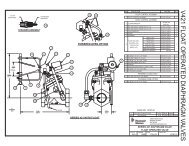
<strong>9000</strong> CONTROL VALVE ASSEMBLY<br />
12<br />
7<br />
6<br />
8<br />
9<br />
13 15<br />
10<br />
11<br />
1<br />
4<br />
2 3<br />
19<br />
5<br />
20<br />
14<br />
32<br />
33<br />
31<br />
22<br />
41<br />
43<br />
42<br />
48<br />
14861-01<br />
VALVE BODY,<strong>9000</strong>,MACHINED<br />
W/O-RINGS(P/Ns 11710 & 12281) 47<br />
24 46 23 21<br />
27<br />
25<br />
45<br />
28<br />
30<br />
26<br />
29<br />
16<br />
17<br />
18<br />
39<br />
40<br />
37<br />
38<br />
24<br />
44<br />
34<br />
36<br />
24<br />
35<br />
BR61500-<strong>9000</strong> Rev C<br />
Item No. QTY Part No. Description<br />
1 ................ 1 .........14861..................Valve Body, <strong>9000</strong><br />
2 ............... 15 ........13242..................Seal, 5600<br />
3 ............... 12 ........14241..................Spacer<br />
4 ................ 1 .........16595..................Spacer, <strong>9000</strong><br />
5 ................ 1 .........42278..................End Cap, Plastic, <strong>9000</strong>/<strong>9100</strong><br />
6 ................ 2 .........13363..................Washer, Hague Drive<br />
7 ................ 2 .........17020..................Screw, STL. Hex Washer,<br />
6-20 x 3/8<br />
8 ................ 2 .........11335 ..................Screw, #4-40<br />
9 ................ 1 .........14921..................Link, Piston Rod<br />
10 .............. 1 .........14919..................Piston, Rod, Upper<br />
11............... 2 .........14309..................Retainer, Piston Rod<br />
12 .............. 1 .........14914..................Piston, <strong>9000</strong>, Upper<br />
13 .............. 2 .........13243..................Plug, End, 5600<br />
14 .............. 2 .........10209..................Quad Ring, -010<br />
15 .............. 2 .........13008..................Retainer, End Plug Seal<br />
16 .............. 1 .........15019..................Link, Piston Rod, <strong>9000</strong>/<strong>9500</strong><br />
17 .............. 1 .........14920..................Rod, Piston, Lower, <strong>9000</strong><br />
18 .............. 1 .........14905..................Pistion, <strong>9000</strong>, Lower<br />
19 .............. 1 .........40952..................O-ring, -030<br />
20 .............. 4 .........15331..................Screw, Hex Washer Head<br />
21 .............. 2 .........13361..................Spacer, 4600<br />
22 .............. 1 .........15215..................Body, Injector, <strong>9000</strong><br />
23 .............. 2 .........13301..................O-ring, -011<br />
24 .............. 3 .........13302..................O-ring, -014<br />
25 .............. 1 .........10227..................Screen, Injector<br />
26 .............. 1 .........10913-1 ..............Nozzle, Injector, #1, Natural<br />
Item No. QTY Part No. Description<br />
27 .............. 1 .........10914-1 ..............Throat, Injector<br />
28 .............. 1 .........13166..................Cap, Injector, 5600<br />
29 .............. 1 .........13303..................O-ring, -021<br />
30 .............. 2 .........13387..................Screw, Hex Washer Head<br />
31 .............. 1 .........15348..................O-ring, -563<br />
32 .............. 1 .........13173..................Retainer, DLFC Button<br />
33 .............. 1 .........12088..................Washer, Flow, 2.4 GPM<br />
34 .............. 1 .........14925..................Brine Valve Stem, <strong>9000</strong><br />
35 .............. 1 .........12626..................Seat, Brine Valve<br />
36 .............. 1 .........13167..................Spacer, Brine Valve<br />
37 .............. 1 .........13165..................Cap, Brine Valve<br />
38 .............. 1 .........11973..................Spring, Brine Valve<br />
39 .............. 1 .........11981-01.............Ring, Retaining, SS<br />
40 .............. 1 .........16098..................Washer, Nylon Brine<br />
41 .............. 1 .........12977..................O-ring, -015<br />
42 .............. 1 .........13245..................Retainer, BLFC<br />
43 .............. 1 .........12094..................Washer, Flow Control, 0.25 GPM<br />
44 .............. 1 .........12550..................Quad Ring, -009<br />
45 .............. 1 .........13244..................Adapter, BLFC<br />
46 .............. 1 .........13497..................Air Disperser, Injector<br />
47 .............. 1 .........11710..................O-ring, -215<br />
48 .............. 1 .........12281..................O-ring, -338<br />
Not Shown<br />
1 .........12128..................Label, 0.25 GPM BLFC<br />
1 .........13333..................Label, Injector<br />
1 .........10760..................Label, 1 GPM, 3 lbs salt/min<br />
<strong>Fleck</strong> <strong>Model</strong> <strong>9000</strong>/<strong>9100</strong>/<strong>9500</strong> OC10 • 7
<strong>9100</strong> CONTROL VALVE ASSEMBLY<br />
15<br />
11<br />
12<br />
13<br />
9<br />
8<br />
5<br />
7<br />
17<br />
16<br />
14<br />
10<br />
4<br />
2<br />
3<br />
6<br />
1<br />
2<br />
3<br />
30<br />
32<br />
31<br />
17<br />
15<br />
20<br />
11 19<br />
13<br />
12<br />
9<br />
18<br />
48<br />
49<br />
39<br />
38<br />
36<br />
21<br />
46<br />
47<br />
23<br />
43<br />
35<br />
44<br />
37<br />
33<br />
34<br />
22<br />
41<br />
42<br />
26<br />
24<br />
40<br />
45<br />
25<br />
28<br />
27<br />
29<br />
16<br />
Item No. QTY Part No. Description<br />
1 ................ 1 .........40688..................Valve Body Assy, <strong>9100</strong><br />
2 ............... 15 ........13242..................Seal, 5600<br />
3 ............... 12 ........14241..................Spacer<br />
4 ................ 1 .........16595..................Spacer, <strong>9000</strong><br />
5 ................ 1 .........42278..................End Cap, Plastic, <strong>9000</strong>/<strong>9100</strong><br />
6 ................ 1 .........40952..................O-ring, -030<br />
7 ................ 4 .........15331..................Screw, Hex Washer Head<br />
8 ................ 1 .........14914..................Piston, <strong>9000</strong>, Upper<br />
9 ................ 2 .........14309..................Retainer, Piston Rod<br />
10 .............. 1 .........14919..................Piston, Rod, Upper<br />
11............... 2 .........13243..................Plug, End, 5600<br />
12 .............. 2 .........13008..................Retainer, End Plug Seal<br />
13 .............. 2 .........10209..................Quad Ring, -010<br />
14 .............. 1 .........14921..................Link, Piston Rod<br />
15 .............. 2 .........11335 ..................Screw, #4-40<br />
16 .............. 2 .........17020..................Screw, STL. Hex Washer,<br />
6-20 x 3/8<br />
17 .............. 2 .........13363..................Washer, Hague Drive<br />
18 .............. 1 .........14905..................Piston, <strong>9000</strong>, Lower<br />
19 .............. 1 .........14920..................Rod, Piston, Lower, <strong>9000</strong><br />
20 .............. 1 .........15019..................Link, Piston, Rod, <strong>9000</strong>/<strong>9500</strong><br />
21 .............. 1 .........41500..................O-ring, <strong>9100</strong> Drain<br />
22 .............. 1 .........15215..................Body, Injector, <strong>9000</strong><br />
23 .............. 2 .........13301..................O-ring, -011<br />
24 .............. 1 .........10227..................Screen, Injector<br />
25 .............. 1 .........10913-1 ..............Nozzle, Injector, #1, Natural<br />
26 .............. 1 .........10914-1 ..............Throat, Injector<br />
27 .............. 1 .........13166..................Cap, Injector, 5600<br />
8 • OC10 <strong>Fleck</strong> <strong>Model</strong> <strong>9000</strong>/<strong>9100</strong>/<strong>9500</strong><br />
Item No. QTY Part No. Description<br />
28 .............. 1 .........13303..................O-ring, -021<br />
29 .............. 2 .........13387..................Screw, Hex Washer Head<br />
30 .............. 1 .........15348..................O-ring, -563<br />
31 .............. 1 .........13173..................Retainer, DLFC Button<br />
32 .............. 1 .........12085..................Washer, Flow, 1.2 GPM<br />
33 .............. 1 .........14925..................Brine Valve Stem, <strong>9000</strong><br />
34 .............. 1 .........12626..................Seat, Brine Valve<br />
35 .............. 1 .........13167..................Spacer, Brine Valve<br />
36 .............. 1 .........13165..................Cap, Brine Valve<br />
37 .............. 1 .........11973 ..................Spring, Brine Valve<br />
38 .............. 1 .........11981-01 .............Ring, Retaining, SS<br />
39 .............. 1 .........16098..................Washer, Nylon Brine<br />
40 .............. 1 .........12977..................O-ring, -015<br />
41 .............. 1 .........13245..................Retainer, BLFC<br />
42 .............. 1 .........12095..................Washer, Flow Control, 0.50 GPM<br />
43 .............. 1 .........12550..................Quad Ring, -009<br />
44 .............. 2 .........13302..................O-ring, -014<br />
45 .............. 1 .........13244..................Adapter, BLFC<br />
46 .............. 1 .........13497..................Air Dispereser, Injector<br />
47 .............. 1 .........13361..................Spacer, 4600<br />
48 .............. 1 .........40538..................Retainer, 32 mm, O-ring DIST,<br />
7000<br />
49 .............. 1 .........61419..................Kit, 1.05" Distributor Adapter<br />
Not Shown<br />
1 .........13333..................Label, Injector<br />
BR61500-<strong>9100</strong> Rev C<br />
1 .........10759..................Label, 0.5 GPM, 1.5 lbs salt/min
<strong>9500</strong> CONTROL VALVE ASSEMBLY<br />
23 29<br />
30<br />
28<br />
25<br />
OPTIONAL 1600 INJECTOR<br />
35<br />
24<br />
26<br />
27<br />
40<br />
39 38<br />
36<br />
37<br />
7<br />
5<br />
9<br />
34<br />
33<br />
41<br />
2<br />
4<br />
1<br />
3<br />
2<br />
10<br />
11<br />
12<br />
14<br />
9<br />
13<br />
8<br />
31<br />
6<br />
20<br />
11<br />
21<br />
14<br />
9<br />
8<br />
22<br />
15<br />
19<br />
17<br />
18<br />
16<br />
15<br />
17<br />
18 19<br />
BR61500-<strong>9500</strong> Rev C<br />
Item No. QTY Part No. Description<br />
1 ................1 ....... 16919 ................Valve Body, <strong>9500</strong>, Machining<br />
2 ...............15 ...... 16101 ................Seal, 2850<br />
3 ...............12 ...... 16638 ................Spacer, <strong>9500</strong>/2850<br />
4 ................1 ....... 17092 ................Spacer, Disc, <strong>9500</strong><br />
5 ................1 ....... 42278-01 ...........End Cap, Plastic, <strong>9500</strong><br />
6 ................1 ....... 16455 ................O-ring, -347<br />
7 ................4 ....... 15331 ................Screw, Hex Washer Head<br />
8 ................2 ....... 17558 ................Disc, Spacer, End Plug<br />
9 ................3 ....... 16394 ................O-ring, -029<br />
10 ..............1 ....... 17110 ................Piston, <strong>9500</strong>, Upper<br />
11 ..............2 ....... 14309 ................Retainer, Piston Rod<br />
12 ..............1 ....... 16957 ................Rod, Piston, <strong>9500</strong><br />
13 ..............2 ....... 16954 ................Plug, End, <strong>9500</strong><br />
14 ..............2 ....... 13008 ................Retainer, End Plug Seal<br />
15 ..............2 ....... 10209 ................Quad Ring, -010<br />
16 ..............1 ....... 14921 ................Link, Piston Rod<br />
17 ..............2 ....... 11335 ................Screw, #4-40<br />
18 ..............2 ....... 17020 ................Screw, STL. Hex Washer,<br />
6-20 x 3/8<br />
19 ..............2 ....... 13363 ................Washer, Hague Drive<br />
20 ..............1 ....... 17111 ................Piston, <strong>9500</strong>, Lower<br />
21 ..............1 ....... 16956 ................Rod, Piston, Lower<br />
Item No. QTY Part No. Description<br />
22 ..............1 ....... 15019 ................Link, Piston Rod, <strong>9000</strong>/<strong>9500</strong><br />
23 ..............2 ....... 14804 ................Screw, Slotted Hex Head<br />
24 ..............1 ....... 15413 ................Fitting, Elbow, Male, 1/2 TX 3/8<br />
NPT<br />
25 ..............1 ....... 17777-03 ...........Body, Injector, 1700<br />
26 ..............1 ....... 14802 ................Throat, Injector<br />
27 ..............1 ....... 14805 ................Gasket, Injector Body<br />
28 ..............1 ....... 14801-05C ........Nozzle, Injector, 5C, White<br />
29 ..............1 ....... 10229 ................Gasket, Injector Body<br />
30 ..............1 ....... 11893 ................Cap, Injector<br />
31 ..............1 ....... 13577 ................O-ring, -226<br />
Optional (1600) Injector Part Number<br />
33 ........................ 17776 ................Body, Injector, 1600<br />
34 ........................ 10328 ................Fitting, Elbow, 90 Deg.<br />
35 ........................ 10913-1 .............Nozzle, Injector, #1, Natural<br />
36 ........................ 10914 ................Throat, Injector<br />
37 ........................ 10227 ................Screen, Injector<br />
38 ........................ 10229 ................Gasket, Injector Body<br />
39 ........................ 11893 ................Cap, Injector<br />
40 ........................ 10692 ................Screw, Slot, Indented Hex Head<br />
41 ........................ 14805 ................Gasket, Injector Body<br />
<strong>Fleck</strong> <strong>Model</strong> <strong>9000</strong>/<strong>9100</strong>/<strong>9500</strong> OC10 • 9
1600 BRINE VALVE SYSTEM (FOR <strong>9500</strong>)<br />
Item No. QTY Part No. Description<br />
1 ................1 ....... 16960 ................Tube, Brine Valve<br />
2 ................1 ....... 10329 ................Fitting, Tube, 3/8 Nut, Brass<br />
3 ................1 ....... 10330 ................Fitting, Sleeve, 3/8 Celcon<br />
4 ................1 ....... 10332 ................Fitting, Insert, 3/8<br />
5 ................1 ....... 12747 ................Fitting, Flow Control<br />
6 ................1 ....... 12550 ................Quad Ring, -009<br />
7 ................1 ....... 12626 ................Seat, Brine Valve<br />
8 ................1 ....... 16958 ................Brine Valve Stem, 1600 Coated<br />
9 ................1 ....... 11982 ................O-ring, -016<br />
10 ..............3 ....... 15137 ................Screw, Hex Washer Mach,<br />
10-24 x 3/8<br />
11 ..............3 ....... 10269 ................Nut, Jam, 3/84 - 16<br />
12 ..............3 ....... 16922 ................Bracket, Brine Valve Mounting<br />
13 ..............1 ....... 10250 ................Ring, Retaining<br />
14 ..............1 ....... 10249 ................Spring, Brine Valve<br />
15 ..............1 ....... 12748-01 ...........Brine Valve Body, 1600<br />
16 ..............2 ....... 10328 ................Fitting, Elbow, 90 Deg.<br />
10 • OC10 <strong>Fleck</strong> <strong>Model</strong> <strong>9000</strong>/<strong>9100</strong>/<strong>9500</strong>
1700 BRINE VALVE SYSTEM (FOR <strong>9500</strong>)<br />
Item No. QTY Part No. Description<br />
1 ................1 ....... 14792 ................Plug, End, Brine Valve<br />
2 ................1 ....... 13201 ................Quad Ring, -020<br />
3 ................1 ....... 12550 ................Quad Ring, -009<br />
4 ................1 ....... 14785-01 ...........Retainer, Flow Control<br />
5 ................2 ....... 14811 ................O-ring, -210, 560CD, Brine<br />
6 ................1 ....... 14795 ................Piston, Brine Valve<br />
7 ................1 ....... 16929 ................Brine Valve Stem, Coated<br />
8 ................1 ....... 15415 ................Fitting, Insert, 1/2" Tube<br />
9 ................1 ....... 16124 ................Fitting, Sleeve, Delrin<br />
10 ..............1 ....... 16123 ................Nut, Brass<br />
11 ..............1 ....... 15137 ................Screw, Hex Washer Mach,<br />
10-24 x 3/8<br />
12 ..............1 ....... 10269 ................Nut, Jam, 3/4 - 16<br />
13 ..............1 ....... 16922 ................Bracket, Brine Valve Mounting<br />
14 ..............2 ....... 10250 ................Ring, Retaining<br />
15 ..............1 ....... 15310 ................Spring, Brine Valve<br />
16 ..............2 ....... 14790 ................Brine Valve Body<br />
17 ..............1 ....... 14798 ................Spacer, 1700, Brine<br />
18 ..............1 ....... 15414 ................Nut, 2900, w/Sleeve<br />
19 ..............1 ....... 15413 ................Fitting, Elbow, Male, 1/2T x 3/8<br />
NPT<br />
20 ..............1 ....... 16959 ................Tube, Brine <strong>9500</strong>/1710, 10.6"<br />
<strong>Fleck</strong> <strong>Model</strong> <strong>9000</strong>/<strong>9100</strong>/<strong>9500</strong> OC10 • 11
<strong>9000</strong> SECOND TANK ASSEMBLY<br />
Item No. QTY Part No. Description<br />
1 ................1 ....... 14864-01 ...........Adapter, <strong>9000</strong>, 2nd Tank, Machd<br />
w/O-rings<br />
2 ................8 ....... 13305 ................O-ring, -119<br />
3 ................1 ....... 11710 ................O-ring, -215<br />
4 ................1 ....... 12281 ................O-ring, -338<br />
5 ................2 ....... 13708-40 ...........Yoke, 1" Sweat<br />
..................1 ....... 15823-XX ..........Yoke Assy. Specify Tank Size<br />
6 ................4 ....... 13255 ................Clip, Mounting<br />
7 ................4 ....... 14202-01 ...........Screw, Hex Washer Mach,<br />
8-32 x 5/16<br />
8 ................4 ....... 15078 ................Adapter, 1" Coupling<br />
12 • OC10 <strong>Fleck</strong> <strong>Model</strong> <strong>9000</strong>/<strong>9100</strong>/<strong>9500</strong>
<strong>9100</strong> SECOND TANK ASSEMBLY<br />
Item No. QTY Part No. Description<br />
1 ................4 ....... 40678 ................Ring, <strong>9100</strong>, Yoke Retainer<br />
2 ................4 ....... 13287 ................O-ring, -123<br />
3 ................1 ....... 14865 ................Adapter Assy, 2nd Tank, <strong>9100</strong><br />
4 ................1 ....... 19054 ................O-ring, -124<br />
5 ................1 ....... 40538 ................Retainer, 32mm, O-ring Dist,<br />
7000<br />
6 ................1 ....... 61419 ................Kit, 1.05" Distributor, Adapter<br />
7 ................1 ....... 18303 ................O-ring, -336<br />
8 ................4 ....... 13255 ................Clip, Mounting<br />
9 ................4 ....... 14202-01 ...........Screw, Hex Washer Mach,<br />
8-32 x 5/16<br />
<strong>Fleck</strong> <strong>Model</strong> <strong>9000</strong>/<strong>9100</strong>/<strong>9500</strong> OC10 • 13
<strong>9500</strong> SECOND TANK ASSEMBLY<br />
Item No. QTY Part No. Description<br />
1 ................1 ....... 13577 ................O-ring, -226<br />
2 ................1 ....... 16455 ................O-ring, -347<br />
3 ................8 ....... 10231 ................Screw, Slot Hex, 1/4 - 20 x 1/2<br />
4 ................4 ....... 17224 ................O-ring, -224<br />
14 • OC10 <strong>Fleck</strong> <strong>Model</strong> <strong>9000</strong>/<strong>9100</strong>/<strong>9500</strong>
3/4" METER ASSEMBLY<br />
Item No. QTY Part No. Description<br />
1 ................1 ....... 14613 ................Flow Straightener<br />
2 ................4 ....... 12473 ................Screw, Hex Washer, 10-24 x 5/8<br />
3 ................1 ....... 14038 ................Meter Cap Assy<br />
4 ................1 ....... 13847 ................O-ring, -137, Std/560CD, Meter<br />
5 ................1 ....... 13509 ................Impeller, Meter<br />
6 ................4 ....... 13314 ................Screw, Slot Ind Hex, 8-18 x .60<br />
7 ................4 ....... 13255 ................Clip, Mounting<br />
8 ................4 ....... 13305 ................O-ring, -119<br />
9 ................1 ....... 15150 ................Meter Cap Assy, Ext<br />
........ 15237 ................Meter Cap Assy, Ext<br />
10 ..............1 ....... 13821 ................Body, Meter, 5600<br />
<strong>Fleck</strong> <strong>Model</strong> <strong>9000</strong>/<strong>9100</strong>/<strong>9500</strong> OC10 • 15
1" METER ASSEMBLY<br />
Item No. QTY Part No. Description<br />
1 ............... 4 ....... 12112 ................Screw, Hex Hd Mach 10-24 x 1/2<br />
2 ............... 1 ....... 15218 ................Meter Cap Assy<br />
........ 15237 ................Meter Cap Assy, EXT<br />
3 ............... 1 ....... 13847 ................O-ring, -137, STD/560CD, Meter<br />
4 ............... 1 ....... 13509 ................Impeller, Meter<br />
....... 13509-01 ...........Impeller, Celcon<br />
5 ............... 1 ....... 13882 ................Post, Meter Impeller<br />
6 ............... 1 ....... 15043 ................Body, Meter, <strong>9000</strong> 1"<br />
7 ............... 1 ....... 14960 ................Flow Straightener, 1"<br />
8 ............... 4 ....... 13305 ................O-ring, -119<br />
9 ............... .2 ....... 15078 ................Adapter, 1" Coupling<br />
10 ............. 2 ....... 13255 ................Clip, Mounting<br />
11 ............. 2 ....... 14202-01 ...........Screw, Hex Washer Mach,<br />
8-32 x 5/16<br />
12 ..............1 ....... 15150 ................Meter Cap Assy, Ext<br />
........ 15237 ................Meter Cap Assy, Ext<br />
16 • OC10 <strong>Fleck</strong> <strong>Model</strong> <strong>9000</strong>/<strong>9100</strong>/<strong>9500</strong>
1-1/2" METER ASSEMBLY<br />
Item No. QTY Part No. Description<br />
1 ................1 ....... 17569 ................Body, Meter, 2850/<strong>9500</strong><br />
2 ................1 ....... 13882 ................Post, Meter Impeller<br />
3 ................1 ....... 13509 ................Impeller, Meter<br />
4 ................1 ....... 13847 ................O-ring, -137, Std/560CD, Meter<br />
5 ................1 ....... 15218 ................Meter Cap Assy<br />
6 ................4 ....... 12112 ................Screw, Hex Hd Mach,<br />
10-24 x 1/2 18-8 S.S.<br />
7 ................1 ....... 17542 ................Flow Straightener, 1 1/2"<br />
8 ................1 ....... 12733 ................O-ring, -132<br />
9 ................1 ....... 17544 ................Fitting, 1 1/2" Quick Connector<br />
10 ..............1 ....... 17543 ................Nut, 1 1/2", Q/C<br />
11 ..............1 ....... 15150 ................Meter Cap Assy, Ext<br />
Not Shown<br />
........ 15237 ................Meter Cap Assy, Ext<br />
1 ....... 17790 ................Sleeve, Meter, 1 1/2" x 1"<br />
<strong>Fleck</strong> <strong>Model</strong> <strong>9000</strong>/<strong>9100</strong>/<strong>9500</strong> OC10 • 17
<strong>9000</strong>/<strong>9100</strong> BYPASS VALVE ASSEMBLY<br />
Item No. QTY Part No. Description<br />
1 ................1 ....... 17290 ................By-Pass Body, 3/4"<br />
........ 17290NP ...........By-Pass Body, 3/4" NP, 5600<br />
........ 13399 ................By-Pass Body, 1"<br />
........ 13399NP ...........By-Pass Body, 1" NP<br />
2 ................1 ....... 14105 ................Seal, By-Pass, 560CD<br />
3 ................1 ....... 11972 ................Plug, By-Pass, w/Wax<br />
4 ................1 ....... 11978 ................Plate, By-Pass, Top<br />
5 ................1 ....... 13604-01 ...........Label, By-Pass, Standard Mount<br />
6 ................8 ....... 15727 ................Screw, Hex Washer Hd,<br />
10-24 x 1/2<br />
7 ................1 ....... 11986 ................Plate, By-Pass, Bottom<br />
8 ................1 ....... 11979 ................Lever, By-Pass<br />
9 ................1 ....... 11989 ................Screw, Sltd Indent,<br />
1/4 - 14 x 1 1/2<br />
18 • OC10 <strong>Fleck</strong> <strong>Model</strong> <strong>9000</strong>/<strong>9100</strong>/<strong>9500</strong>
BYPASS VALVE ASSEMBLY<br />
Item No. QTY Part No. Description<br />
1 ................2 ....... 13305 ................O-ring, -119<br />
2 ................2 ....... 13255 ................Clip, Mounting<br />
3 ................2 ....... 13314 ................Screw, Slot Ind Hex, 8-18 x .60<br />
4A .............1 ....... 18706 ................Yoke, 1", NPT, Plastic<br />
........ 18706-02 ...........Yoke, 3/4", NPT, Plastic<br />
4B .............1 ....... 41027-01 ...........Yoke, 3/4", NPT, Cast, Machd<br />
........ 41026-01 ...........Yoke, 1", NPT, Cast, Machd, SS<br />
<strong>Fleck</strong> <strong>Model</strong> <strong>9000</strong>/<strong>9100</strong>/<strong>9500</strong> OC10 • 19
1710 BRINE VALVE SYSTEM (FOR <strong>9500</strong>)<br />
Item No. QTY Part No. Description<br />
1 ................1 ....... 41202 ................Brine Valve, 1700, Plastic, Top<br />
2 ................1 ....... 14785-01 ...........Retainer, Flow Control<br />
3 ................2 ....... 14811 ................O-ring, -210, 560CD, Brine<br />
4 ................1 ....... 14798 ................Spacer, 1700, Brine<br />
5 ................1 ....... 14795 ................Piston, Brine Valve<br />
6 ................1 ....... 41429 ................Stem, Brine, 1710, Plastic, <strong>9500</strong><br />
7 ................1 ....... 41201 ................Brine Valve, 1700, Plastic, Bottm<br />
8 ................1 ....... 12550 ................Ring, Quad, -009<br />
9 ................1 ....... 17908 ................Sleeve, Brine Valve Stem<br />
10 ..............1 ....... 41547 ................O-ring, 2mm x 35mm<br />
11 ..............1 ....... 15310 ................Spring, Brine Valve<br />
12 ..............1 ....... 10250 ................Ring, Retaining<br />
13 ..............1 ....... 17906-01 ...........Guide, Brine Valve Stem<br />
14 ..............4 ....... 14202-01 ...........Screw, Hex Washer, Mach, 8-32<br />
x 5/16"<br />
15 ..............2 ....... 41056 ................Nut Assy, 1/2" Plastic<br />
16 ..............1 ....... 41493-XX ..........Label, BLFC, 1710 (Specify<br />
GPM)<br />
17 ..............1 ..................................Washer, Flow (Specify GPM)<br />
18 ..............3 ....... 15415 ................Fitting, Insert, 1/2", Tube<br />
19 ..............1 ....... 15414 ................Nut, 2900, w/Sleeve<br />
20 ..............1 ....... 16959 ................Tube, Brine <strong>9500</strong>/1700, 10.6"<br />
20 • OC10 <strong>Fleck</strong> <strong>Model</strong> <strong>9000</strong>/<strong>9100</strong>/<strong>9500</strong>
2300 SAFETY BRINE VALVE<br />
Item No. QTY Part No. Description<br />
1 ................1 ....... 60027-00 ...........Safety Brine Valve, 2300, Less<br />
Elbow<br />
2 ................1 ....... 10138 ................Ball, 3/8", Brass<br />
3 ................1 ....... 11566 ................Ball Stop, Slow Fill<br />
4 ................1 ....... 10328 ................Fitting, Elbow, 90 Deg.<br />
1/4 NPT x 3/8T<br />
5 ................1 ....... 10332 ................Fitting, Insert, 3/8<br />
6 ................1 ....... 10330 ................Fitting, Sleeve, 3/8 Celcon<br />
7 ................1 ....... 10329 ................Fitting, Tube, 3/8 Nut, Brass<br />
8 ................1 ....... 10186 ................Nut, Hex, 10-32<br />
9 ................1 ....... 60002 ................Air Check, #500<br />
10 ..............1 ....... 10149 ................Rod, Float<br />
11 ..............1 ....... 10700 ................Float Assy, Blue/White<br />
12 ..............3 ....... 10150 ................Grommet, .30 Dia<br />
<strong>Fleck</strong> <strong>Model</strong> <strong>9000</strong>/<strong>9100</strong>/<strong>9500</strong> OC10 • 21
2310 SAFETY BRINE VALVE<br />
Item No. QTY Part No. Description<br />
1 ................1 ....... 19645 ................Body, Safety Brine Valve, 2310<br />
2 ................1 ....... 19803 ................Safety Brine Valve Assy<br />
3 ................1 ....... 19804 ................Screw, Sckt Hd, Set, 10-24 x .75<br />
4 ................1 ....... 19805 ................Nut, Hex, 10-24, Nylon Black<br />
5 ................1 ....... 19652-01 ...........Poppet Assy, SBV w/O-ring<br />
6 ................1 ....... 19649 ................Flow Dispenser<br />
7 ................1 ....... 11183 ................O-ring, -017<br />
8 ................1 ....... 19647 ................Elbow, Safety Brine Valve<br />
9 ................2 ....... 19625 ................Nut Assy, 3/8" Plastic<br />
10 ..............1 ....... 18312 ................Retainer, Drain<br />
11 ..............1 ....... 60014 ................Safety Brine Valve Assy, 2310<br />
12 ..............2 ....... 10150 ................Grommet, .30 Dia<br />
13 ..............1 ....... 60068 ................Float Assy, 2310, w/30" Rod<br />
14 ..............1 ....... 60002 ................Air Check, #500<br />
22 • OC10 <strong>Fleck</strong> <strong>Model</strong> <strong>9000</strong>/<strong>9100</strong>/<strong>9500</strong>
2350 SAFETY BRINE VALVE<br />
Item No. QTY Part No. Description<br />
1 ................1 ....... 60038 ................Safety Brine Valve, 2350<br />
1A .............1 ....... 61024 ................Actuator Assy, 2350 Brine<br />
2 ................1 ....... 60026-30 ...........Float Assy, 400A/2350, 30"<br />
Red/Wht<br />
3 ................1 ....... 60009-00 ...........Air Check, #900, Commercial<br />
Less Fittings<br />
Not Shown:<br />
........ 60009-01 ...........Air Check, #900, Commercial,<br />
HW Less Fittings<br />
1 ....... 18603 ................Fitting Assy, 900 Air Check 2350<br />
<strong>Fleck</strong> <strong>Model</strong> <strong>9000</strong>/<strong>9100</strong>/<strong>9500</strong> OC10 • 23
GENERAL SERVICE HINTS FOR METER<br />
CONTROL<br />
Problem: Softener delivers hard water<br />
Reason: Reserve capacity has been exceeded.<br />
Correction: Check salt dosage requirements and reset<br />
program wheel to provide additional reserve.<br />
Reason: Program wheel is not rotating with meter output.<br />
Correction: Pull cable out of meter cover and rotate manually.<br />
Program wheel must move without binding and clutch must<br />
give positive clicks when program wheel strikes regeneration<br />
stop. If it does not, replace timer.<br />
Reason: Meter is not measuring flow.<br />
Correction: Check meter with meter checker.<br />
24 • OC10 <strong>Fleck</strong> <strong>Model</strong> <strong>9000</strong>/<strong>9100</strong>/<strong>9500</strong>
TROUBLESHOOTING<br />
Problem Cause Correction<br />
Water conditioner fails to<br />
regenerate.<br />
Electrical service to unit has been<br />
interrupted<br />
Timer is defective.<br />
Power failure.<br />
Assure permanent electrical service (check fuse,<br />
plug, pull chain, or switch)<br />
Replace timer.<br />
Reset time of day.<br />
Hard water. By-pass valve is open. Close by-pass valve.<br />
No salt is in brine tank.<br />
Injector screen plugged.<br />
Insufficient water flowing into brine tank.<br />
Hot water tank hardness.<br />
Leak at distributor tube.<br />
Internal valve leak.<br />
Add salt to brine tank and maintain salt level<br />
above water level.<br />
Clean injector screen.<br />
Check brine tank fill time and clean brine line flow<br />
control if plugged.<br />
Repeated flushings of the hot water tank is<br />
required.<br />
Make sure distributor tube is not cracked. Check<br />
O-ring and tube pilot.<br />
Replace seals and spacers and/or piston.<br />
Unit used too much salt. Improper salt setting. Check salt usage and salt setting.<br />
Excessive water in brine tank.<br />
See "Excessive water in brine tank".<br />
Loss of water pressure. Iron buildup in line to water conditioner. Clean line to water conditioner.<br />
Loss of mineral through drain<br />
line.<br />
Iron buildup in water conditioner.<br />
Inlet of control plugged due to foreign<br />
material broken loose from pipes by recent<br />
work done on plumbing system.<br />
Air in water system.<br />
Improperly sized drain line flow control.<br />
Clean control and add mineral cleaner to mineral<br />
bed. Increase frequency of regeneration.<br />
Remove piston and clean control.<br />
Assure that well system has proper air eliminator<br />
control. Check for dry well condition.<br />
Check for proper drain rate.<br />
Iron in conditioned water. Fouled mineral bed. Check backwash, brine draw, and brine tank fill.<br />
Increase frequency of regeneration. Increase<br />
backwash time.<br />
Excessive water in brine tank. Plugged drain line flow control. Clean flow control.<br />
Plugged injector system.<br />
Timer not cycling.<br />
Foreign material in brine valve.<br />
Foreign material in brine line flow control.<br />
Clean injector and screen.<br />
Replace timer.<br />
Replace brine valve seat and clean valve.<br />
Clean brine line flow control.<br />
Softener fails to draw brine. Drain line flow control is plugged. Clean drain line flow control.<br />
Injector is plugged.<br />
Injector screen plugged.<br />
Line pressure is too low.<br />
Internal control leak<br />
Service adapter did not cycle.<br />
Clean injector<br />
Clean screen.<br />
Increase line pressure to 20 psi<br />
Change seals, spacers, and piston assembly.<br />
Check drive motor and switches.<br />
Control cycles continuously. Misadjusted, broken, or shorted switch. Determine if switch or timer is faulty and replace it,<br />
or replace complete power head.<br />
Drain flows continuously. Valve is not programming correctly. Check timer program and positioning of control.<br />
Replace power head assembly if not positioning<br />
properly.<br />
Foreign material in control.<br />
Internal control leak.<br />
Remove power head assembly and inspect bore.<br />
Remove foreign material and check control in<br />
various regeneration positions.<br />
Replace seals and piston assembly.<br />
<strong>Fleck</strong> <strong>Model</strong> <strong>9000</strong>/<strong>9100</strong>/<strong>9500</strong> OC10 • 25
<strong>9000</strong>/<strong>9100</strong>/<strong>9500</strong> METER FLOW DATA<br />
<strong>9000</strong> Meter Flow Data<br />
<strong>9100</strong> Meter Flow Data<br />
<strong>9500</strong> Meter Flow Data<br />
26 • OC10 <strong>Fleck</strong> <strong>Model</strong> <strong>9000</strong>/<strong>9100</strong>/<strong>9500</strong>
<strong>9000</strong>/<strong>9100</strong>/<strong>9500</strong> INJECTOR FLOW DATA<br />
(1600 SERIES INJECTORS)<br />
<strong>Fleck</strong> <strong>Model</strong> <strong>9000</strong>/<strong>9100</strong>/<strong>9500</strong> OC10 • 27
<strong>9500</strong> INJECTOR FLOW DATA (1600<br />
&1700 SERIES INJECTORS)<br />
1600 Series Injectors<br />
1700 Series Injectors<br />
28 • OC10 <strong>Fleck</strong> <strong>Model</strong> <strong>9000</strong>/<strong>9100</strong>/<strong>9500</strong>
<strong>9000</strong> CONTROL DIMENSIONS<br />
<strong>Fleck</strong> <strong>Model</strong> <strong>9000</strong>/<strong>9100</strong>/<strong>9500</strong> OC10 • 29
<strong>9100</strong> CONTROL DIMENSIONS<br />
30 • OC10 <strong>Fleck</strong> <strong>Model</strong> <strong>9000</strong>/<strong>9100</strong>/<strong>9500</strong>
<strong>9500</strong> CONTROL DIMENSIONS<br />
<strong>Fleck</strong> <strong>Model</strong> <strong>9000</strong>/<strong>9100</strong>/<strong>9500</strong> OC10 • 31
WATER CONDITIONER FLOW<br />
DIAGRAMS<br />
1 In Service Position<br />
3 Tanks Switching Position<br />
(Meter Initiated Regeneration)<br />
2 Backwash Position<br />
4 Brine Draw Position<br />
5 Slow Rinse<br />
32 • OC10 <strong>Fleck</strong> <strong>Model</strong> <strong>9000</strong>/<strong>9100</strong>/<strong>9500</strong>
WATER CONDITIONER FLOW<br />
DIAGRAMS continued<br />
6 Brine Tank Fill Position<br />
7 Rapid Rinse Position<br />
8 In Service Position, Tanks Switched<br />
<strong>Fleck</strong> <strong>Model</strong> <strong>9000</strong>/<strong>9100</strong>/<strong>9500</strong> OC10 • 33
<strong>9000</strong>/<strong>9500</strong> WIRING DIGRAM<br />
19752 Rev B<br />
34 • OC10 <strong>Fleck</strong> <strong>Model</strong> <strong>9000</strong>/<strong>9100</strong>/<strong>9500</strong>
SERVICE ASSEMBLIES<br />
Brine Line Flow Controls (<strong>9000</strong>/<strong>9100</strong>):<br />
60022-12 ....................BLFC, .125 GPM, 5000/5600/<strong>9000</strong>/<strong>9100</strong><br />
60022-25 ....................BLFC, .25 GPM, 5000/5600/<strong>9000</strong>/<strong>9100</strong><br />
60022-50 ....................BLFC, .50 GPM, 5000/5600/<strong>9000</strong>/<strong>9100</strong><br />
60022-100 ..................BLFC, 1.0 GPM, 5000/5600/<strong>9000</strong>/<strong>9100</strong><br />
60350..........................Brine Valve Assy, <strong>9000</strong>/<strong>9100</strong><br />
Brine Line Flow Controls (<strong>9500</strong>):<br />
60020-25 ....................BLFC, .25 GPM, 1600<br />
60020-50 ....................BLFC, .50 GPM, 1600<br />
60020-100 ..................BLFC, 1.0 GPM, 1600<br />
Brine Valve Assemblies:<br />
60037-610 ..................Brine Valve, <strong>9500</strong>/1600, .25 GPM,<br />
Cold & HW 180°<br />
60037-620 ..................Brine Valve, <strong>9500</strong>/1600, .50 GPM,<br />
Cold & HW 180°<br />
60037-630 ..................Brine Valve, <strong>9500</strong>/1600, 1.0 GPM,<br />
Cold & HW 180°<br />
60350..........................Brine Valve Assy <strong>9000</strong>/<strong>9100</strong>,<br />
Cold & HW 180°<br />
60350-01 ....................Brine Valve Assy, <strong>9000</strong>/<strong>9100</strong>/Twinfl100,<br />
Cold & HW 180°<br />
1700 Brine Valve Assembies (<strong>9500</strong>):<br />
60039-XX....................Brine Valve, 1700/<strong>9500</strong>, Cold &<br />
HW 180°<br />
Bypass Assemblies:<br />
60040SS .....................Bypass Valve, 5600, 3/4" NPT<br />
60041SS .....................Bypass Valve, 5600, 1" NPT<br />
60049..........................Bypass Plastic Assy<br />
Injector Assemblies (<strong>9000</strong>/<strong>9100</strong>):<br />
60385-X ......................Injector Assembly (specify size of<br />
injector)<br />
Injector Number DLFC Number BLFC Number<br />
Red #0......00.............Blank.... 0..............Blank.... 0<br />
White #1....01.............1.2........ 1..............0.25...... 1<br />
Blue #2 .....02.............1.5........ 2..............0.50...... 2<br />
Yellow #3 ..03.............2.0........ 3..............1.00...... 3<br />
Green #4...04.............2.4........ 4<br />
3.0........ 5<br />
3.5........ 6<br />
4.0........ 7<br />
5.0........ 8<br />
7.0........ 9<br />
Injector Assemblies (<strong>9500</strong>):<br />
60381-03 ....................Injector Assy, 1700, #3, Cold & HW 150°<br />
60381-04 ....................Injector Assy, 1700, #4, Cold & HW 150°<br />
60381-05 ....................Injector Assy, 1700, #5, Cold & HW 150°<br />
60381-06 ....................Injector Assy, 1700, #6, Cold & HW 150°<br />
60480-01 ....................Injector Assy, 1600, #1, Plastic,<br />
Cold Water<br />
60480-02 ....................Injector Assy, 1600, #2, Plastic,<br />
Cold Water<br />
60480-03 ....................Injector Assy, 1600, #3, Plastic,<br />
Cold Water<br />
60480-04 ....................Injector Assy, 1600, #4, Plastic,<br />
Cold Water<br />
60481-21 ....................Injector Assy, 1600, #1, SS, HW 180°<br />
60481-21 ....................Injector Assy, 1600, #2, SS, HW 180°<br />
60481-21 ....................Injector Assy, 1600, #3, SS, HW 180°<br />
60481-21 ....................Injector Assy, 1600, #4, SS, HW 180°<br />
Meter Assemblies (<strong>9000</strong>/<strong>9100</strong>):<br />
15078-01 ....................Adapter, 1" Coupling<br />
60086..........................Meter Assy, 5600/<strong>9000</strong>/<strong>9100</strong>,<br />
3/4" Std/Range<br />
60087..........................Meter Assy, 5600/<strong>9000</strong>/<strong>9100</strong>, 3/4", Ext<br />
60389..........................Meter Assy, <strong>9000</strong>/<strong>9100</strong>, 1"<br />
60389NP .....................Meter Assy, <strong>9000</strong>/<strong>9100</strong>, 1", N/P<br />
60389-20 ....................Meter Assy, <strong>9000</strong>/<strong>9100</strong>, 1", BSP/Metric<br />
60390..........................Meter Assy, <strong>9000</strong>/<strong>9100</strong>, 1", Ext<br />
60390NP .....................Meter Assy, <strong>9000</strong>/<strong>9100</strong>, 1", Ext, N/P<br />
60390-20 ....................Meter Assy, <strong>9000</strong>/<strong>9100</strong>, 1",<br />
Ext/BSP/Metric<br />
60612..........................Meter Assy, <strong>9000</strong>/<strong>9100</strong>, 1", Std Range,<br />
HW 150°<br />
60612NP .....................Meter Assy, <strong>9000</strong>/<strong>9100</strong>, 1", Std Range,<br />
HW 150°, NP<br />
14038..........................Meter Cap Assy<br />
15150..........................Meter Cap Assy, Ext<br />
15218..........................Meter Cap Assy<br />
15218NP .....................Meter Cap Assy, Std, NP<br />
15237..........................Meter Cap Assy, Ext<br />
15237NP .....................Meter Cap Assy, Ext, NP<br />
13509..........................Impeller, Meter<br />
13509-01 ....................Impeller, Celcon, HW 150°<br />
<strong>Fleck</strong> <strong>Model</strong> <strong>9000</strong>/<strong>9100</strong>/<strong>9500</strong> OC10 • 35
SERVICE ASSEMBLIES continued<br />
Meter Assemblies (<strong>9500</strong>):<br />
60610-01 ....................Meter, 2850/<strong>9500</strong>, 1 1/2" Std<br />
60610-01HW ..............Meter, 2850/<strong>9500</strong>, 1 1/2" Std, HW 150°<br />
60610-01NP ...............Meter, 2850/<strong>9500</strong>, 1 - 1/2" Std, N/P<br />
60610-02 ....................Meter, 2850/<strong>9500</strong>, 1 - 1/2" Ext<br />
60610-02HW ..............Meter, 2850/<strong>9500</strong>, 1 1/2" Ext, HW 150°<br />
60610-02NP ...............Meter, 2850/<strong>9500</strong>, 1 - 1/2" Ext, N/P<br />
60610-21 ....................Meter, 2850/<strong>9500</strong>, 1 - 1/2" Std/BSP<br />
Metric<br />
60610-21NP ...............Meter, 2850/<strong>9500</strong>, 1 - 1/2" Std/BSP<br />
Metric, Nickel Plated<br />
60610-22 ....................Meter, 2850/<strong>9500</strong>, 1 - 1/2" Ext/BSP<br />
Metric<br />
60610-22NP ...............Meter, 2850/<strong>9500</strong>, 1 - 1/2" Ext/BSP<br />
Metric/Nickel Plated<br />
60611-01HW ...............Meter, 2850/<strong>9500</strong>, 1" Sleeve, 1 1/2" Std,<br />
HW 150°<br />
60611-01 .....................Meter, 2850/<strong>9500</strong>, 1" Sleeve, 1 1/2" Std<br />
Meter<br />
60611-01NP ................Meter, 2850/<strong>9500</strong>, 1" Sleeve, NP<br />
1 1/2" Std Meter<br />
60611-02 .....................Meter, 2850/<strong>9500</strong>, 1" Sleeve, 1 1/2" Ext<br />
Meter<br />
60611-02NP ................Meter, 2850/<strong>9500</strong>, 1" Sleeve, NP 1 1/2"<br />
Ext Meter<br />
17790..........................Sleeve, Meter, 1 1/2" x 1" (NOTE: when<br />
reducing a 1-1/2" meter to a 1" meter,<br />
the program wheel and timer settings<br />
must be changed to a 1" meter size)<br />
Meter Checker Kits:<br />
60460..........................Meter Checker Kit, Std<br />
60461..........................Meter Checket Kit, Ext<br />
Piston Assemblies:<br />
60108..........................Piston Assy, <strong>9500</strong>, Upper<br />
60108-01 ....................Piston Assy, <strong>9500</strong>, Upper, HW 180°<br />
60109..........................Piston Assy, <strong>9500</strong>, Lower<br />
60109-01 ....................Piston Assy, <strong>9500</strong>, Lower HW, 180°<br />
60400..........................Piston Assy, <strong>9000</strong>/<strong>9100</strong>, Top<br />
60400-01 ....................Piston Assy, <strong>9000</strong>/<strong>9100</strong>, HW Upper,<br />
180°<br />
60401..........................Piston Assy, <strong>9000</strong>/<strong>9100</strong>, Lower<br />
60401-01 ....................Piston Assy, <strong>9000</strong>/<strong>9100</strong> Lower, HW 180°<br />
Seal & Spacer Kits:<br />
60125..........................Seal & Spacer Kit, 5600/<strong>9000</strong> Top<br />
60125-20 ....................Seal & Spacer Kit, Top, 559 PE Cold<br />
and Chloramine<br />
60125HW....................Seal & Spacer Kit, <strong>9000</strong>/<strong>9100</strong>, Upper<br />
HW 180°<br />
60133-01 ....................Seal & Spacer Kit, <strong>9500</strong>, Lower, Cold &<br />
HW 180°<br />
60133-20 ....................Seal & Spacer Kit, <strong>9500</strong>, Lower<br />
60133-30 ....................Seal & Spacer Kit, <strong>9500</strong>, Lower<br />
60134..........................Seal & Spacer Kit, <strong>9500</strong>, Upper, Cold &<br />
HW 180°<br />
60134-20 ....................Seal & Spacer Kit, <strong>9500</strong>, Upper<br />
60134-30 ....................Seal & Spacer Kit, <strong>9500</strong>, Upper<br />
60421..........................Seal & Spacer Kit, <strong>9000</strong>/<strong>9100</strong>, Bottom<br />
60421-20 ....................Seal & Spacer Kit, <strong>9000</strong>/<strong>9100</strong>, Bottom<br />
559PE<br />
60421HW....................Seal & Spacer Kit, <strong>9000</strong>/<strong>9100</strong>, Bottom,<br />
HW 180°<br />
Second Tank Assemblies (<strong>9000</strong>):<br />
14202-01 ....................Screw, Hex Washer Mach, 8-32 x 5/16<br />
18-8 S.S.<br />
13255..........................Clip, Mounting<br />
15078-01 ....................Adapter Assy, 1" Coupling<br />
14864-01 ....................Adapter, <strong>9000</strong>/<strong>9100</strong>, 2nd Tank, Machd<br />
w/O-rings<br />
14864-01NP ...............Adapter, <strong>9000</strong>/<strong>9100</strong>, 2nd Tank, Machd,<br />
NP<br />
15823-06 ....................Yoke Assy, 6" Tank & 6" Tube<br />
15823-06NP ...............Yoke Assy, 6" Tank, NP 6" Tubes<br />
15823-12 ....................Yoke Assy, 6" - 12" Tank, 8 1/2 Tube<br />
15823-12NP ...............Yoke Assy, 6" - 12" Tank, NP 8 1/2"<br />
Tubes<br />
15823-14 ....................Yoke Assy, 14" Tank, 10 1/2" Tube<br />
15823-14NP ...............Yoke Assy, 14" Tank, NP 10 1/2" Tube<br />
15823-16 ....................Yoke Assy, 16" Tank, 12 1/2" Tube<br />
15823-16NP ...............Yoke Assy, 16" Tank, NP 12 1/2" Tube<br />
Second Tank Assemblies (<strong>9100</strong>):<br />
60425-12 ....................Tube Assy, <strong>9100</strong>, 6-12" Tanks<br />
60425-16 ....................Tube Assy, <strong>9100</strong>, 13-16" Tanks<br />
14865..........................Adapter Assy, 2nd Tank, <strong>9100</strong><br />
61419..........................Kit, 1.05" Distributor Adapter<br />
Second Tank Assemblies (<strong>9500</strong>):<br />
16919-01 ....................Valve Body, <strong>9500</strong> Machd<br />
16919-01NP ...............Valve Body, <strong>9500</strong> Machd, NP<br />
16919-21 ....................Valve Body, <strong>9500</strong> BSP, Mtrc, Machd<br />
16919-21NP ...............Valve Body, <strong>9500</strong> BSP, Mtrc, Machd<br />
Nickel Plated<br />
60715-16 ....................Tube Assy, <strong>9500</strong>, 2nd Tank for 14" to 16"<br />
Tanks<br />
60715-16NP ...............Tube Assy, <strong>9500</strong>, 2nd Tank, NP for 14"<br />
to 16" Tanks<br />
60715-20 ....................Tube Assy, <strong>9500</strong>, 2nd Tank for 20" Tanks<br />
60715-24 ....................Tube Assy, <strong>9500</strong>, 2nd Tank for 20" and<br />
24" Tanks<br />
60715-24NP ...............Tube Assy, <strong>9500</strong>, 2nd Tank, Nickel for<br />
20-24" Tanks<br />
Single Piece Plastic End Cap Assemblies<br />
61701-01 ....................Plug Assy, End Cap <strong>9000</strong>/<strong>9100</strong><br />
61701-02 ....................Plug Assy, End Cap <strong>9500</strong><br />
Tools:<br />
12763..........................Stuffer Tool Assy, 5600/<strong>9000</strong><br />
13061..........................Puller Assy, Port Ring<br />
13759..........................Tool, DLFC Retainer<br />
Valve Body Assembly (<strong>9100</strong>):<br />
40688..........................Valve Body Assy, <strong>9100</strong><br />
18303..........................O-ring, -336<br />
18569..........................Retainer, Tank Seal<br />
©2011 <strong>Pentair</strong> <strong>Residential</strong> <strong>Filtration</strong>, LLC 40944 Rev E MR11