Fleck Model 9000/9100/9500 - Pentair Residential Filtration
Fleck Model 9000/9100/9500 - Pentair Residential Filtration
Fleck Model 9000/9100/9500 - Pentair Residential Filtration

You also want an ePaper? Increase the reach of your titles
YUMPU automatically turns print PDFs into web optimized ePapers that Google loves.
INSTALLATION & START-UP continued<br />
18. Cycle timer into backwash position. Turn manual knob so<br />
that the micro switch rides on the first set of pins. In this<br />
position the tanks switch (lower piston) and the control<br />
valve moves to the backwash position (upper piston). Wait<br />
until the positioning of upper and lower pistons stops before<br />
advancing the timer further. If advanced too fast the control<br />
will not home into the In Service position (it will not advance<br />
to any other position). To correct this, rotate the manual<br />
knob back to In Service and start again into backwash.<br />
NOTE: Once valve positions itself into the backwash<br />
cycle, the homing circuit locks in.<br />
19. With all the air backwashed, slowly cycle the timer to the<br />
brine position; rapid rinse; and brine tank refill. Wait for the<br />
control drive motor to position itself in each cycle and stop,<br />
before advancing on to the next position.<br />
20. Once back in the In Service position, cycle the control valve<br />
again into the backwash position. The tanks switch again,<br />
and air head backwashes out of the other tank. Cycle the<br />
control back to the In Service position. Leave the timer in<br />
the open position. DO NOT insert meter cable yet.<br />
NOTE: Two motors are available.<br />
1/15 RPM has 82 minute regeneration time.<br />
1/30 RPM has 164 minute regeneration time.<br />
Valve To Tank Installation<br />
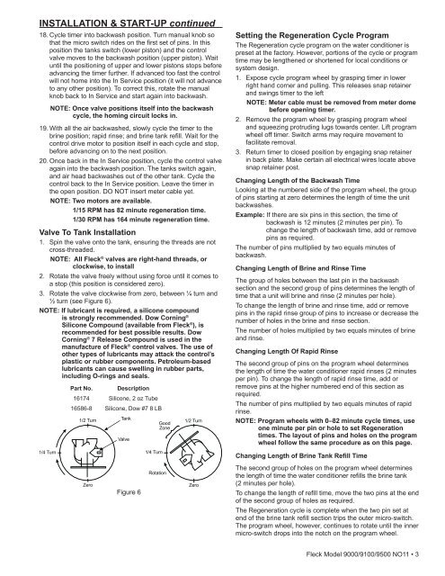
1. Spin the valve onto the tank, ensuring the threads are not<br />
cross-threaded.<br />
NOTE: All <strong>Fleck</strong> ® valves are right-hand threads, or<br />
clockwise, to install<br />
2. Rotate the valve freely without using force until it comes to<br />
a stop (this position is considered zero).<br />
3. Rotate the valve clockwise from zero, between ¼ turn and<br />
½ turn (see Figure 6).<br />
NOTE: If lubricant is required, a silicone compound<br />
is strongly recommended. Dow Corning ®<br />
Silicone Compound (available from <strong>Fleck</strong> ® ), is<br />
recommended for best possible results. Dow<br />
Corning ® 7 Release Compound is used in the<br />
manufacture of <strong>Fleck</strong> ® control valves. The use of<br />
other types of lubricants may attack the control’s<br />
plastic or rubber components. Petroleum-based<br />
lubricants can cause swelling in rubber parts,<br />
including O-rings and seals.<br />
Part No. Description<br />
16174 Silicone, 2 oz Tube<br />
16586-8 Silicone, Dow #7 8 LB<br />
Setting the Regeneration Cycle Program<br />
The Regeneration cycle program on the water conditioner is<br />
preset at the factory. However, portions of the cycle or program<br />
time may be lengthened or shortened for local conditions or<br />
system design.<br />
1. Expose cycle program wheel by grasping timer in lower<br />
right hand corner and pulling. This releases snap retainer<br />
and swings timer to the left<br />
NOTE: Meter cable must be removed from meter dome<br />
before opening timer.<br />
2. Remove the program wheel by grasping program wheel<br />
and squeezing protruding lugs towards center. Lift program<br />
wheel off timer. Switch arms may require movement to<br />
facilitate removal.<br />
3. Return timer to closed position by engaging snap retainer<br />
in back plate. Make certain all electrical wires locate above<br />
snap retainer post.<br />
Changing Length of the Backwash Time<br />
Looking at the numbered side of the program wheel, the group<br />
of pins starting at zero determines the length of time the unit<br />
backwashes.<br />
Example: If there are six pins in this section, the time of<br />
backwash is 12 minutes (2 minutes per pin). To<br />
change the length of backwash time, add or remove<br />
pins as required.<br />
The number of pins multiplied by two equals minutes of<br />
backwash.<br />
Changing Length of Brine and Rinse Time<br />
The group of holes between the last pin in the backwash<br />
section and the second group of pins determines the length of<br />
time that a unit will brine and rinse (2 minutes per hole).<br />
To change the length of brine and rinse time, add or remove<br />
pins in the rapid rinse group of pins to increase or decrease the<br />
number of holes in the brine and rinse section.<br />
The number of holes multiplied by two equals minutes of brine<br />
and rinse.<br />
Changing Length Of Rapid Rinse<br />
The second group of pins on the program wheel determines<br />
the length of time the water conditioner rapid rinses (2 minutes<br />
per pin). To change the length of rapid rinse time, add or<br />
remove pins at the higher numbered end of this section as<br />
required.<br />
The number of pins multiplied by two equals minutes of rapid<br />
rinse.<br />
NOTE: Program wheels with 0–82 minute cycle times, use<br />
one minute per pin or hole to set Regeneration<br />
times. The layout of pins and holes on the program<br />
wheel follow the same procedure as on this page.<br />
Changing Length of Brine Tank Refill Time<br />
Figure 6<br />
The second group of holes on the program wheel determines<br />
the length of time the water conditioner refills the brine tank<br />
(2 minutes per hole).<br />
To change the length of refill time, move the two pins at the end<br />
of the second group of holes as required.<br />
The Regeneration cycle is complete when the two pin set at<br />
end of the brine tank refill section trips the outer micro-switch.<br />
The program wheel, however, continues to rotate until the inner<br />
micro-switch drops into the notch on the program wheel.<br />
<strong>Fleck</strong> <strong>Model</strong> <strong>9000</strong>/<strong>9100</strong>/<strong>9500</strong> NO11 • 3