VDO Universal Sender Kit Instructions
VDO Universal Sender Kit Instructions
VDO Universal Sender Kit Instructions

Create successful ePaper yourself
Turn your PDF publications into a flip-book with our unique Google optimized e-Paper software.
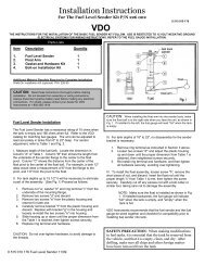
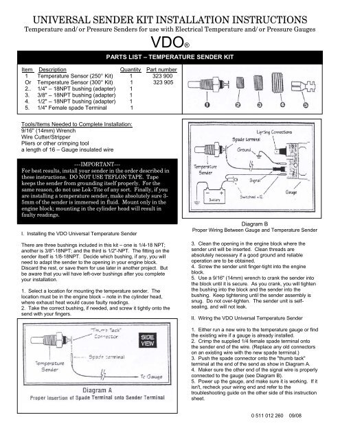
UNIVERSAL SENDER KIT INSTALLATION INSTRUCTIONS<br />
Temperature and/or Pressure <strong>Sender</strong>s for use with Electrical Temperature and/or Pressure Gauges<br />
<strong>VDO</strong>®<br />
PARTS LIST – TEMPERATURE SENDER KIT<br />
Item Description Quantity Part number<br />
1 Temperature Sensor (250° <strong>Kit</strong>) 1 323 900<br />
Or Temperature Sensor (300° <strong>Kit</strong>) 1 323 905<br />
2.. 1/4" – 18NPT bushing (adapter) 1<br />
3. 3/8" – 18NPT bushing (adapter) 1<br />
4. 1/2" – 18NPT bushing (adapter) 1<br />
5. 1/4" Female spade Terminal 1<br />
Tools/Items Needed to Complete Installation:<br />
9/16" (14mm) Wrench<br />
Wire Cutter/Stripper<br />
Pliers or other crimping tool<br />
a length of 16 – Gauge insulated wire<br />
---IMPORTANT---<br />
For best results, install your sender in the order described in<br />
these instructions. DO NOT USE TEFLON TAPE. Tape<br />
keeps the sender from grounding itself properly. For the<br />
same reason, do not use Lok-Tite of any sort. Finally, if you<br />
are installing a temperature sender, make absolutely sure 3-<br />
5mm of the sender is immersed in fluid. Mount only in the<br />
engine block; mounting in the cylinder head will result in<br />
faulty readings.<br />
I. Installing the <strong>VDO</strong> <strong>Universal</strong> Temperature <strong>Sender</strong><br />
There are three bushings included in this kit – one is 1/4-18 NPT;<br />
another is 3/8"-18NPT; and the third is 1/2"-NPT. The fitting on the<br />
sender itself is 1/8-18NPT. Decide which bushing, if any, you will<br />
need to adapt the sender to the opening in your engine block.<br />
Discard the rest, or save them for use later in another project. But<br />
be aware that you will have left-over bushings after you complete<br />
your installation.<br />
1. Select a location for mounting the temperature sender. The<br />
location must be in the engine block – note in the cylinder head,<br />
where exhaust heat would cause faulty readings.<br />
2. Take the correct bushing, if needed, and screw it tightly onto the<br />
send with your fingers.<br />
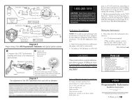
Diagram B<br />
Proper Wiring Between Gauge and Temperature <strong>Sender</strong><br />
3. Clean the opening in the engine block where the<br />
sender unit will be inserted. Clean threads are<br />
absolutely necessary if a good ground and reliable<br />
operation are to be obtained.<br />
4. Screw the sender unit finger-tight into the engine<br />
block.<br />
5. Use a 9/16" (14mm) wrench to crank the sender into<br />
the block until it is secure. As you crank, you will tighten<br />
the bushing into the block and the sender into the<br />
bushing. Keep tightening until the sender assembly is<br />
snug. Do not over-tighten. The sender unit is selfsealing,<br />
and will not leak.<br />
II. Wiring the <strong>VDO</strong> <strong>Universal</strong> Temperature <strong>Sender</strong><br />
1. Either run a new wire to the temperature gauge or find<br />
the existing wire if a gauge is already installed.<br />
2. Crimp the supplied 1/4 female spade terminal onto<br />
the sender end of the wire. (Replace any old connectors<br />
on an existing wire with the new spade terminal.)<br />
3. Push the spade connector onto the "thumb tack"<br />
terminal at the end of the send as show in Diagram A.<br />
4. Maker sure the other end of the signal wire is properly<br />
connected to the gauge (see Diagram B).<br />
5. Power up the gauge, and make sure it is working. If it<br />
isn't, recheck your wiring end and refer to the<br />
troubleshooting guide on the other side of this instruction<br />
sheet.<br />
00''' 0 511 012 260 09/08
PARTS LIST – PRESSURE SENDER KIT<br />
Item Description Quantity Part Number<br />
1. Pressure <strong>Sender</strong> (80 PSI <strong>Kit</strong>) 1 360 900<br />
or Pressure <strong>Sender</strong> (150 PSI <strong>Kit</strong>) 1 360 905<br />
2. 1/4" - 18 NPT bushing (adapter) 1<br />
3. 3/8" - 18 NPT bushing (adapter) 1<br />
4. 1/2" - 14 NPT bushing (adapter) 1<br />
Tools/Items Needed to Complete Installation:<br />
3/4" (18mm) wrench<br />
Pliers or other crimping tool (optional)<br />
Wire cutters/stripper<br />
a length of 16-gauge insulated wire<br />
1/4" ring terminal (optional)<br />
I. Installation the <strong>VDO</strong> <strong>Universal</strong> Pressure <strong>Sender</strong><br />
There are three bushings included in this kit – one is 1/4" – 18 NPT,<br />
another is 3/8" – 18 NPT, and third is 1/2"-14 NPT. The fitting on the<br />
sender itself is 1/8" – 18 NPT. Decide which bushing if any, you will<br />
need to adapt the sender to the opening in the engine block.<br />
Discard the rest, or save them for use later in another project. But<br />
be aware that you will have left over bushing after you complete<br />
your installation.<br />
1. Select a location for mounting the pressure sender.<br />
2. Take the correct bushing, if needed, and screw it tightly onto the<br />
sender with your finders.<br />
3. Clean the opening in he engine block where the sender unit will<br />
be inserted. Clean threads are absolutely necessary if a good<br />
ground and reliable operation are to be obtained.<br />
4. Screw the sender unit finger-tight into the engine block.<br />
5. Use a 3/4" (18mm) wrench to crank the sender into the block. As<br />
you crank, you will tighten the bushing into the block and the sender<br />
into the bushing. Keep tightening until the sender assembly is snug.<br />
Do not over tighten. The sender is self-sealing, and will not leak.<br />
Diagram C<br />
Proper Wiring Between Gauge and Pressure <strong>Sender</strong><br />
II. Wiring the <strong>VDO</strong> <strong>Universal</strong> Pressure <strong>Sender</strong><br />
1. Either run a new wire to the pressure gauge or find<br />
the existing wire if a pressure gauge is ready to be<br />
installed.<br />
2. Crimp a ring terminal onto the sender end of wire.<br />
3. Attached the ring terminal to the terminal on the<br />
sender.<br />
4. Make sure the other end of the signal wire is<br />
properly connected to the pressure gauge (see<br />
diagram C)<br />
5. Turn on the power, and make sure the gauge is<br />
working, if it isn't recheck your wiring. (See<br />
"Troubleshooting" below.)<br />
_--- TROUBLESHOOTING--<br />
TEMPERATURE – PRESSURE SENDERS<br />
Do not use Teflon tape on the threads. It will interfere with the sender ground. <strong>Sender</strong> threads are tapered pipe threads and are self-sealing.<br />
Temperature senders are most accurate when installed in the aftermarket intake manifold. It is also acceptable to use the OEM engine manufacturing<br />
specified location. Installing in the cylinder head can cause high readings due to the exhaust manifold heat. Do not use tee adapters, reducing, or angle<br />
adapters for temperature sender since the sender tip or bulb will not be immersed in the water flow.<br />
SENDER TESTING<br />
<strong>Sender</strong>s can be tested with an ohmmeter that measure from 10 to 2,000 ohms. Connect the positive lead from the tester to the sender terminal and the<br />
negative lead to a good ground. The following readings will occur if the sender is operating property.<br />
Temperature <strong>Sender</strong> Cold - 700 ohms<br />
Hot (250 degrees) - 22 ohms<br />
Pressure <strong>Sender</strong> Engine Off - 10 ohms<br />
Engine running 40 psi = 105 ohms; 60 psi = 152 ohms<br />
<strong>VDO</strong> LIMITED WARRANTY<br />
<strong>VDO</strong> Corporation warrants all merchandise against defects in factory workmanship and materials for a period of 24 months after purchase. This warranty applies to the<br />
first retail purchaser and covers only those products exposed to normal use or service. Provisions of this warranty shall not apply to a <strong>VDO</strong> product used for a purpose<br />
for which it is not designed, or which has been altered in any way that would be detrimental to the performance of like of the product, or misapplication, misuse,<br />
negligence or accident. On any part or product found to be defective after examination by <strong>VDO</strong>, <strong>VDO</strong> will only repair or replace the merchandise through the original<br />
seller dealer or on a direct basis. <strong>VDO</strong> assumes no responsibility for diagnosis, removal and/or installation labor, loss of vehicle use, loss of time, inconvenience or any<br />
other consequential expenses. The warranties here in are in lieu of any other expressed or implied warranties, including any implied 00''' warranty of merchantability or<br />
fitness, and any other obligation on the part of <strong>VDO</strong> or seller dealer.(NOTE: This is a "Limited Warranty" as defined by the Magnuson-Moss Warranty Act of 1975)<br />
0 511 012 260 09/08