TB-1 - JANADA
TB-1 - JANADA
TB-1 - JANADA

Create successful ePaper yourself
Turn your PDF publications into a flip-book with our unique Google optimized e-Paper software.
Date: 2 nd October 2003<br />
Issue: A<br />
Technical Bulletin<br />
The Structure of Non-blocking HF Switching Matrix Systems for Radio Surveillance<br />
1. Purpose<br />
The purpose of this bulletin is to explain the structure of non-blocking HF signal switching matrix<br />
systems for radio surveillance, as they grow in size and complexity from a simple 16 x 32 signal<br />
exchange unit to a large matrix system with 512 receivers or more.<br />
2. Definition of Systems<br />
Radio surveillance is the monitoring of the radio frequency spectrum for technical, military or legal<br />
reasons. In the short-wave spectrum (3-30MHz) this is most usually done by connecting a<br />
relatively large number of receivers to a number of specialised antennas, usually antennas with<br />
directivity gain and/or restricted frequency coverage.<br />
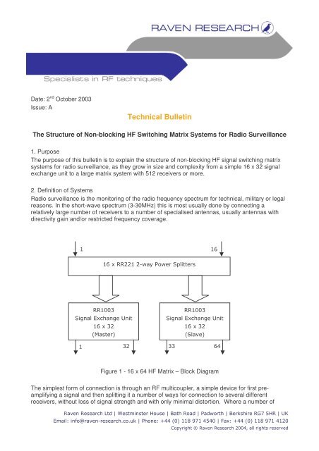
1 16<br />
16 x RR221 2-way Power Splitters<br />
RR1003<br />
Signal Exchange Unit<br />
16 x 32<br />
(Master)<br />
RR1003<br />
Signal Exchange Unit<br />
16 x 32<br />
(Slave)<br />
1<br />
32<br />
33<br />
64<br />
Figure 1 - 16 x 64 HF Matrix – Block Diagram<br />
The simplest form of connection is through an RF multicoupler, a simple device for first preamplifying<br />
a signal and then splitting it a number of ways for connection to several different<br />
receivers, without loss of signal strength and with only minimal distortion. Where a number of<br />
Raven Research Ltd | Westminster House | Bath Road | Padworth | Berkshire RG7 5HR | UK<br />
Email: info@raven-research.co.uk | Phone: +44 (0) 118 971 4540 | Fax: +44 (0) 118 971 4120<br />
Copyright © Raven Research 2004, all rights reserved
Raven Research Limited<br />
antennas are available it is desirable to make all of these antennas available to all of the receivers<br />
in the system and for this an antenna matrix switching system is required.<br />
In this paper we are exclusively discussing low noise, high dynamic range front-end switching<br />
matrix systems. The inputs are directly connected to the antennas and the matrix routes these offair<br />
signals directly to the appropriate RF receivers.<br />
The matrix systems so formed are non-blocking in the forward direction. That is any number of<br />
outputs can be connected simultaneously to the same input.<br />
3. Matrix Systems<br />
16 x 32 Matrix Unit<br />
The current standard for HF signal switching is the Raven Research RR1003. This is a 16 input x<br />
32 output switching matrix, sometimes referred to as a signal exchange unit (SEU). It is a single<br />
19” rack mounting unit, which is operated either under remote control or from the optional front<br />
panel.<br />
16 x 64 Matrix Systems<br />
As the matrix system is expanded to accommodate more receivers than 32, more of these SEUs<br />
are connected together with RF signal splitting devices, acting to distribute the signals to the<br />
available receivers.<br />
1 16<br />
RR1151 Multicoupler 16 x 4-way Set<br />
RR1003<br />
RR1003<br />
RR1003<br />
RR1003<br />
Signal Exchange<br />
Unit<br />
Signal Exchange<br />
Unit<br />
Signal Exchange<br />
Unit<br />
Signal Exchange<br />
Unit<br />
16 x 32<br />
16 x 32<br />
16 x 32<br />
16 x 32<br />
(Master)<br />
(Master)<br />
(Master)<br />
(Master)<br />
1<br />
32<br />
33<br />
64<br />
65<br />
96<br />
97<br />
128<br />
Figure 2 - 16 x 128 HF Matrix System – Block Diagram<br />
The first expansion is to accommodate 64 receivers and this is usually achieved by a passive<br />
splitting of the signal at the front end and an increase in gain (+3dB) of the RR1003 unit, in order<br />
to compensate for the splitting loss. The system is illustrated in<br />
Page 2 of 4
Raven Research Limited<br />
Figure 1<br />
For such a simple expansion, control will be by a master-slave set-up, with one SEU acting as the<br />
master, the other as a slave.<br />
16 x 128 HF Matrix<br />
The next expansion of the outputs will be 96/128. This will require the addition of an active<br />
multicoupler at the front end. This is needed to preserve the noise figure and dynamic range of the<br />
system, as a passive 4-way split is considered too lossy (>6dB) to allow in a surveillance system.<br />
Up to 128 outputs can be accommodated using the RR1151 multicoupler unit. In this unit, up to 16<br />
multicouplers are contained in a single rack-mounted unit, each multicoupler splitting the input<br />
signal 4 ways. The matrix system is illustrated in<br />
Figure 2.<br />
Control of the system is most effectively implemented by means of a system command processor,<br />
such as the RR1555. This is a single control unit, which features a front panel man-machine<br />
interface for local control and a remote control port. The function of the unit is to accept system<br />
commands (appropriate to the size of the total matrix system) and compute the individual<br />
commands to be sent to the individual equipment units. The unit has a number of local control<br />
ports for sending local unit commands.<br />
1<br />
8<br />
9<br />
16<br />
8 x 8-way<br />
RR1110<br />
Multicouplers<br />
8 x 8-way<br />
RR1110<br />
Multicouplers<br />
128 outputs<br />
128 outputs<br />
4 x RR1003<br />
4 x RR1003<br />
1<br />
128<br />
129<br />
256<br />
Rack 1<br />
Rack 2<br />
Figure 3 - 16 x 256 HF Matrix – Block Diagram<br />
Page 3 of 5
Raven Research Limited<br />
4. Further Expansion of the Number of Outputs<br />
Expansion up to 512 receiver outputs is now a matter of adding more signal exchange units, with<br />
ever more front-end multicouplers. For 256 outputs and above, the RR1110-8/16 series of<br />
multicouplers are used. These are individual rack-mounting multicoupler units.<br />
The current standard for the minimum spatial layout for a matrix with 128 outputs is a single 19”<br />
equipment rack, 37U high (1645mm). However, it is prudent to allow much more space than this<br />
for a new system, wherever possible, as radio receiving systems tend to grow in capacity with time<br />
to accommodate an ever increasing work load.<br />
It can be convenient to design larger systems, with more than 128 outputs, as a series of 128<br />
output subsystems, as this gives a rough guide to the size and cost at the outset. Thus a 16 x 256<br />
system would comprise two racks of 128 outputs but the multicouplers would be changed to 8-way<br />
units with eight multicoupler units accommodated in each rack. This is illustrated in Figure 3. For<br />
512 outputs four racks are used and the multicouplers need to be 16-way units, distributing signals<br />
over all four racks. For 1028 outputs, eight racks are needed and the multicouplers are 32-way<br />
units.<br />
5. Expansion of Number of Inputs<br />
When the number of input signals (antennas) rises above 16, there is a major impact on the<br />
architecture and cost of the RF matrix system. In principle, it requires the size and cost of the<br />
system to double, relative to the size of a similar matrix with the same number of outputs but less<br />
than 16 inputs.<br />
1<br />
16<br />
17<br />
32<br />
16 x 64<br />
Matrix System<br />
16 x 64<br />
Matrix System<br />
RR1401A<br />
32 x SPDT<br />
RF Switching Unit<br />
RR1401A<br />
32 x SPDT<br />
RF Switching Unit<br />
1<br />
32<br />
33<br />
64<br />
Rack 1<br />
Rack 2<br />
Figure 4 - 32 x 64 HF Matrix - Block Diagram<br />
Page 4 of 5
Raven Research Limited<br />
Thus the 32 x 64 matrix system is illustrated in the block diagram of Figure 4. It is apparent that<br />
the really comprises two matrix systems, each with up to 16 inputs, with the outputs combined by a<br />
series of single pole double throw RF switches. These switches feature in the Raven Research<br />
inventory as the RR1401A series.<br />
Again, the control of the system is usually done, using a system command processor.<br />
Page 5 of 5