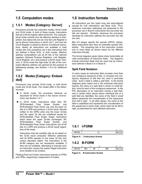
- Page 1 and 2: ® Power ISA Version 2.03 September
- Page 3 and 4: Version 2.03 Preface The roots of t
- Page 5 and 6: Version 2.03 Table of Contents Pref
- Page 7 and 8: Version 2.03 Chapter 5. Vector Proc
- Page 9 and 10: Version 2.03 D.8 Move To/From Speci
- Page 11 and 12: Version 2.03 5.7.1 32-Bit Mode . .
- Page 13 and 14: Version 2.03 4.6 Invalid Real Addre
- Page 15 and 16: Version 2.03 8.6 Debugger Notify Ha
- Page 17 and 18: Version 2.03 5.8 Fixed-Point Select
- Page 19 and 20: Version 2.03 Figures Preface ......
- Page 21 and 22: Version 2.03 40. MMU Control and St
- Page 23 and 24: Version 2.03 Book I: Power ISA User
- Page 25 and 26: Version 2.03 Chapter 1. Introductio
- Page 27 and 28: Version 2.03 GPR, FPR, or VR (e.g.
- Page 29 and 30: Version 2.03 SPR(x) Special Purpose
- Page 31 and 32: Version 2.03 An instruction in a ca
- Page 33: Version 2.03 CR 32 63 “Condition
- Page 37 and 38: Version 2.03 1.6.19 EVX-FORM 0 6 11
- Page 39 and 40: Version 2.03 SPR (11:20) Field used
- Page 41 and 42: Version 2.03 for each virtual page,
- Page 43 and 44: Version 2.03 beq done loop: cmplwi
- Page 45 and 46: Version 2.03 Chapter 2. Branch Proc
- Page 47 and 48: Version 2.03 or (RB) (unsigned comp
- Page 49 and 50: Version 2.03 Programming Note Many
- Page 51 and 52: Version 2.03 Branch I-form Branch C
- Page 53 and 54: Version 2.03 2.5 Condition Register
- Page 55 and 56: Version 2.03 2.6 System Call Instru
- Page 57 and 58: Version 2.03 Chapter 3. Fixed-Point
- Page 59 and 60: Version 2.03 3.2.3 Program Priority
- Page 61 and 62: Version 2.03 Load Byte and Zero D-f
- Page 63 and 64: Version 2.03 Load Halfword Algebrai
- Page 65 and 66: Version 2.03 3.3.2.1 64-bit Fixed-P
- Page 67 and 68: Version 2.03 3.3.3 Fixed-Point Stor
- Page 69 and 70: Version 2.03 Store Word D-form Stor
- Page 71 and 72: Version 2.03 3.3.4 Fixed-Point Load
- Page 73 and 74: Version 2.03 3.3.6 Fixed-Point Move
- Page 75 and 76: Version 2.03 Store String Word Imme
- Page 77 and 78: Version 2.03 3.3.8 Fixed-Point Arit
- Page 79 and 80: Version 2.03 Subtract From Immediat
- Page 81 and 82: Version 2.03 Add to Zero Extended X
- Page 83 and 84: Version 2.03 Divide Word XO-form di
- Page 85 and 86:
Version 2.03 Divide Doubleword XO-f
- Page 87 and 88:
Version 2.03 Compare Logical Immedi
- Page 89 and 90:
Version 2.03 3.3.10.1 64-bit Fixed-
- Page 91 and 92:
Version 2.03 OR Immediate Shifted D
- Page 93 and 94:
Version 2.03 NOR X-form Equivalent
- Page 95 and 96:
Version 2.03 3.3.12.1 64-bit Fixed-
- Page 97 and 98:
Version 2.03 Rotate Left Word Immed
- Page 99 and 100:
Version 2.03 3.3.13.1.1 64-bit Fixe
- Page 101 and 102:
Version 2.03 Rotate Left Doubleword
- Page 103 and 104:
Version 2.03 Shift Right Algebraic
- Page 105 and 106:
Version 2.03 3.3.14 Move To/From Sy
- Page 107 and 108:
Version 2.03 Move To Condition Regi
- Page 109 and 110:
Version 2.03 3.3.14.1 Move To/From
- Page 111 and 112:
Version 2.03 Chapter 4. Floating-Po
- Page 113 and 114:
Version 2.03 the FPRs with no conve
- Page 115 and 116:
Version 2.03 59 Floating-Point Zero
- Page 117 and 118:
Version 2.03 due to the invalid ope
- Page 119 and 120:
Version 2.03 Programming Note The F
- Page 121 and 122:
Version 2.03 When an exception occu
- Page 123 and 124:
Version 2.03 When Invalid Operation
- Page 125 and 126:
Version 2.03 4.4.5 Inexact Exceptio
- Page 127 and 128:
Version 2.03 4.5.2 Execution Model
- Page 129 and 130:
Version 2.03 Load Floating-Point Si
- Page 131 and 132:
Version 2.03 4.6.3 Floating-Point S
- Page 133 and 134:
Version 2.03 Store Floating-Point D
- Page 135 and 136:
Version 2.03 4.6.4 Floating-Point M
- Page 137 and 138:
Version 2.03 Floating Multiply [Sin
- Page 139 and 140:
Version 2.03 Floating Reciprocal Sq
- Page 141 and 142:
Version 2.03 Floating Negative Mult
- Page 143 and 144:
Version 2.03 Floating Convert To In
- Page 145 and 146:
Version 2.03 Floating Round to Inte
- Page 147 and 148:
Version 2.03 4.6.8 Floating-Point S
- Page 149 and 150:
Version 2.03 Move To FPSCR Bit 0 X-
- Page 151 and 152:
Version 2.03 Chapter 5. Vector Proc
- Page 153 and 154:
Version 2.03 Quadword Word 0 Word 1
- Page 155 and 156:
Version 2.03 halfword, or word resp
- Page 157 and 158:
Version 2.03 5.5 Vector Integer Ope
- Page 159 and 160:
Version 2.03 If an exception occurs
- Page 161 and 162:
Version 2.03 5.7.2 Vector Load Inst
- Page 163 and 164:
Version 2.03 5.7.3 Vector Store Ins
- Page 165 and 166:
Version 2.03 5.7.4 Vector Alignment
- Page 167 and 168:
Version 2.03 Vector Pack Signed Hal
- Page 169 and 170:
Version 2.03 Vector Unpack High Pix
- Page 171 and 172:
Version 2.03 5.8.2 Vector Merge Ins
- Page 173 and 174:
Version 2.03 5.8.3 Vector Splat Ins
- Page 175 and 176:
Version 2.03 5.8.6 Vector Shift Ins
- Page 177 and 178:
Version 2.03 5.9 Vector Integer Ins
- Page 179 and 180:
Version 2.03 Vector Add Unsigned By
- Page 181 and 182:
Version 2.03 Vector Subtract Unsign
- Page 183 and 184:
Version 2.03 5.9.1.3 Vector Integer
- Page 185 and 186:
Version 2.03 5.9.1.4 Vector Integer
- Page 187 and 188:
Version 2.03 Vector Multiply-Sum Si
- Page 189 and 190:
Version 2.03 5.9.1.5 Vector Integer
- Page 191 and 192:
Version 2.03 5.9.1.6 Vector Integer
- Page 193 and 194:
Version 2.03 5.9.1.7 Vector Integer
- Page 195 and 196:
Version 2.03 Vector Minimum Signed
- Page 197 and 198:
Version 2.03 5.9.2 Vector Integer C
- Page 199 and 200:
Version 2.03 Vector Compare Greater
- Page 201 and 202:
Version 2.03 5.9.4 Vector Integer R
- Page 203 and 204:
Version 2.03 Vector Shift Right Alg
- Page 205 and 206:
Version 2.03 5.10 Vector Floating-P
- Page 207 and 208:
Version 2.03 5.10.2 Vector Floating
- Page 209 and 210:
Version 2.03 Vector Convert from Si
- Page 211 and 212:
Version 2.03 5.10.4 Vector Floating
- Page 213 and 214:
Version 2.03 5.10.5 Vector Floating
- Page 215 and 216:
Version 2.03 5.11 Vector Status and
- Page 217 and 218:
Version 2.03 Chapter 6. Signal Proc
- Page 219 and 220:
Version 2.03 has occurred in the up
- Page 221 and 222:
Version 2.03 If the exception is en
- Page 223 and 224:
Version 2.03 6.3.7 SPE Instructions
- Page 225 and 226:
Version 2.03 Vector Add Signed, Sat
- Page 227 and 228:
Version 2.03 Vector Compare Greater
- Page 229 and 230:
Version 2.03 Vector Divide Word Uns
- Page 231 and 232:
Version 2.03 Vector Load Double int
- Page 233 and 234:
Version 2.03 Vector Load Word into
- Page 235 and 236:
Version 2.03 Vector Load Word into
- Page 237 and 238:
Version 2.03 Vector Multiply Halfwo
- Page 239 and 240:
Version 2.03 Vector Multiply Halfwo
- Page 241 and 242:
Version 2.03 Vector Multiply Halfwo
- Page 243 and 244:
Version 2.03 Vector Multiply Halfwo
- Page 245 and 246:
Version 2.03 Vector Multiply Halfwo
- Page 247 and 248:
Version 2.03 Vector Multiply Halfwo
- Page 249 and 250:
Version 2.03 Vector Multiply Halfwo
- Page 251 and 252:
Version 2.03 Vector Multiply Halfwo
- Page 253 and 254:
Version 2.03 Initialize Accumulator
- Page 255 and 256:
Version 2.03 Vector Multiply Word L
- Page 257 and 258:
Version 2.03 Vector Multiply Word L
- Page 259 and 260:
Version 2.03 Vector Multiply Word S
- Page 261 and 262:
Version 2.03 Vector Multiply Word U
- Page 263 and 264:
Version 2.03 Vector Rotate Left Wor
- Page 265 and 266:
Version 2.03 Vector Shift Right Wor
- Page 267 and 268:
Version 2.03 Vector Store Word of T
- Page 269 and 270:
Version 2.03 Vector Subtract Unsign
- Page 271 and 272:
Version 2.03 Chapter 7. Embedded Fl
- Page 273 and 274:
Version 2.03 Denormalized numbers o
- Page 275 and 276:
Version 2.03 7.3 Embedded Floating-
- Page 277 and 278:
Version 2.03 Vector Floating-Point
- Page 279 and 280:
Version 2.03 Vector Floating-Point
- Page 281 and 282:
Version 2.03 Vector Convert Floatin
- Page 283 and 284:
Version 2.03 7.3.3 SPE.Embedded Flo
- Page 285 and 286:
Version 2.03 Floating-Point Single-
- Page 287 and 288:
Version 2.03 Floating-Point Single-
- Page 289 and 290:
Version 2.03 Convert Floating-Point
- Page 291 and 292:
Version 2.03 Floating-Point Double-
- Page 293 and 294:
Version 2.03 Floating-Point Double-
- Page 295 and 296:
Version 2.03 Convert Floating-Point
- Page 297 and 298:
Version 2.03 Convert Floating-Point
- Page 299 and 300:
Version 2.03 7.4 Embedded Floating-
- Page 301 and 302:
Version 2.03 Table 3: Embedded Floa
- Page 303 and 304:
Version 2.03 Table 7: Embedded Floa
- Page 305 and 306:
Version 2.03 Chapter 8. Legacy Move
- Page 307 and 308:
Version 2.03 Chapter 9. Legacy Inte
- Page 309 and 310:
Version 2.03 Multiply Accumulate Hi
- Page 311 and 312:
Version 2.03 Multiply Accumulate Lo
- Page 313 and 314:
Version 2.03 Multiply High Halfword
- Page 315 and 316:
Version 2.03 Negative Multiply Accu
- Page 317 and 318:
Version 2.03 Appendix A. Suggested
- Page 319 and 320:
Version 2.03 If FPSCR RN = 0b01 the
- Page 321 and 322:
Version 2.03 A.2 Floating-Point Con
- Page 323 and 324:
Version 2.03 Large Operand: FPSCR F
- Page 325 and 326:
Version 2.03 A.4 Floating-Point Rou
- Page 327 and 328:
Version 2.03 Appendix B. Vector RTL
- Page 329 and 330:
Version 2.03 Appendix C. Embedded F
- Page 331 and 332:
Version 2.03 C.3 Convert from Doubl
- Page 333 and 334:
Version 2.03 C.5 Convert to Single-
- Page 335 and 336:
Version 2.03 Appendix D. Assembler
- Page 337 and 338:
Version 2.03 D.2.3 Branch Mnemonics
- Page 339 and 340:
Version 2.03 D.4 Subtract Mnemonics
- Page 341 and 342:
Version 2.03 These codes are reflec
- Page 343 and 344:
Version 2.03 D.7.2 Operations on Wo
- Page 345 and 346:
Version 2.03 Load Address This mnem
- Page 347 and 348:
Version 2.03 Appendix E. Programmin
- Page 349 and 350:
Version 2.03 Multiple-precision shi
- Page 351 and 352:
Version 2.03 E.2.5 Conversion from
- Page 353 and 354:
Version 2.03 E.4 Vector Unaligned S
- Page 355 and 356:
Version 2.03 Book II: Power ISA Vir
- Page 357 and 358:
Version 2.03 Chapter 1. Storage Mod
- Page 359 and 360:
Version 2.03 Each program can acces
- Page 361 and 362:
Version 2.03 cause additional locat
- Page 363 and 364:
Version 2.03 1.7 Shared Storage Thi
- Page 365 and 366:
Version 2.03 Programming Note The f
- Page 367 and 368:
Version 2.03 Programming Note Becau
- Page 369 and 370:
Version 2.03 1.8.1 Concurrent Modif
- Page 371 and 372:
Version 2.03 Chapter 2. Effect of O
- Page 373 and 374:
Version 2.03 Chapter 3. Storage Con
- Page 375 and 376:
Version 2.03 3.2.2 Data Cache Instr
- Page 377 and 378:
Version 2.03 description assumes th
- Page 379 and 380:
Version 2.03 Programming Note This
- Page 381 and 382:
Version 2.03 Data Cache Block set t
- Page 383 and 384:
Version 2.03 3.2.2.1 Obsolete Data
- Page 385 and 386:
Version 2.03 Store Word Conditional
- Page 387 and 388:
Version 2.03 3.3.3 Memory Barrier I
- Page 389 and 390:
Version 2.03 Enforce In-order Execu
- Page 391 and 392:
Version 2.03 Chapter 4. Time Base 4
- Page 393 and 394:
Version 2.03 Programming Note Since
- Page 395 and 396:
Version 2.03 Chapter 5. External Co
- Page 397 and 398:
Version 2.03 Appendix A. Assembler
- Page 399 and 400:
Version 2.03 Appendix B. Programmin
- Page 401 and 402:
Version 2.03 B.2 Lock Acquisition a
- Page 403 and 404:
Version 2.03 B.3 List Insertion Thi
- Page 405 and 406:
Version 2.03 Book III-S: Power ISA
- Page 407 and 408:
Version 2.03 Chapter 1. Introductio
- Page 409 and 410:
Version 2.03 the execution of a Ve
- Page 411 and 412:
Version 2.03 Chapter 2. Logical Par
- Page 413 and 414:
Version 2.03 2.5 Logical Partition
- Page 415 and 416:
Version 2.03 Chapter 3. Branch Proc
- Page 417 and 418:
Version 2.03 3.3 Branch Processor I
- Page 419 and 420:
Version 2.03 Chapter 4. Fixed-Point
- Page 421 and 422:
Version 2.03 4.3.5 Software-use SPR
- Page 423 and 424:
Version 2.03 4.4.2 OR Instruction o
- Page 425 and 426:
Version 2.03 Move To Special Purpos
- Page 427 and 428:
Version 2.03 Move To Machine State
- Page 429 and 430:
Version 2.03 Chapter 5. Storage Con
- Page 431 and 432:
Version 2.03 stream being executed)
- Page 433 and 434:
Version 2.03 5.7.2.3 Storage Contro
- Page 435 and 436:
Version 2.03 5.7.5 Virtual Address
- Page 437 and 438:
Version 2.03 5.7.6 Virtual to Real
- Page 439 and 440:
Version 2.03 A virtual page is mapp
- Page 441 and 442:
Version 2.03 The 62-bit real addres
- Page 443 and 444:
Version 2.03 not necessarily perfor
- Page 445 and 446:
Version 2.03 5.8 Storage Control At
- Page 447 and 448:
Version 2.03 5.9 Storage Control In
- Page 449 and 450:
Version 2.03 information used in ad
- Page 451 and 452:
Version 2.03 SLB Move From Entry VS
- Page 453 and 454:
Version 2.03 Move To Segment Regist
- Page 455 and 456:
Version 2.03 5.9.3.3 TLB Management
- Page 457 and 458:
Version 2.03 TLB Invalidate All tlb
- Page 459 and 460:
Version 2.03 Programming Note The e
- Page 461 and 462:
Version 2.03 Chapter 6. Interrupts
- Page 463 and 464:
Version 2.03 6.3 Interrupt Synchron
- Page 465 and 466:
Version 2.03 Programming Note For i
- Page 467 and 468:
Version 2.03 6.5 Interrupt Definiti
- Page 469 and 470:
Version 2.03 If the contents of the
- Page 471 and 472:
Version 2.03 to fetch a branch targ
- Page 473 and 474:
Version 2.03 Programming Note These
- Page 475 and 476:
Version 2.03 Execution resumes at e
- Page 477 and 478:
Version 2.03 6.8 Interrupt Prioriti
- Page 479 and 480:
Version 2.03 Chapter 7. Timer Facil
- Page 481 and 482:
Version 2.03 “Assembler Extended
- Page 483 and 484:
Version 2.03 Chapter 8. Debug Facil
- Page 485 and 486:
Version 2.03 Programming Note Proce
- Page 487 and 488:
Version 2.03 Chapter 9. External Co
- Page 489 and 490:
Version 2.03 Chapter 10. Synchroniz
- Page 491 and 492:
Version 2.03 Notes: 1. The effect o
- Page 493 and 494:
Version 2.03 Appendix A. Assembler
- Page 495 and 496:
Version 2.03 Appendix B. Example Pe
- Page 497 and 498:
Version 2.03 reflected in Performan
- Page 499 and 500:
Version 2.03 Programming Note Time
- Page 501 and 502:
Version 2.03 32 Contents of SIAR an
- Page 503 and 504:
Version 2.03 Appendix C. Example Tr
- Page 505 and 506:
Version 2.03 Appendix D. Interpreta
- Page 507 and 508:
Version 2.03 Book III-E: Power ISA
- Page 509 and 510:
Version 2.03 Chapter 1. Introductio
- Page 511 and 512:
Version 2.03 1.6 Synchronization Th
- Page 513 and 514:
Version 2.03 Chapter 2. Branch Proc
- Page 515 and 516:
Version 2.03 2.3 Branch Processor I
- Page 517 and 518:
Version 2.03 Return From Machine-Ch
- Page 519 and 520:
Version 2.03 Chapter 3. Fixed-Point
- Page 521 and 522:
Version 2.03 3.3.4 External Process
- Page 523 and 524:
Version 2.03 3.4 Fixed-Point Proces
- Page 525 and 526:
Version 2.03 Move To Special Purpos
- Page 527 and 528:
Version 2.03 Move From Device Contr
- Page 529 and 530:
Version 2.03 3.4.2 External Process
- Page 531 and 532:
Version 2.03 Store Byte by External
- Page 533 and 534:
Version 2.03 Data Cache Block Store
- Page 535 and 536:
Version 2.03 Data Cache Block Touch
- Page 537 and 538:
Version 2.03 Load Floating-Point Do
- Page 539 and 540:
Version 2.03 Load Vector by Externa
- Page 541 and 542:
Version 2.03 Chapter 4. Storage Con
- Page 543 and 544:
Version 2.03 4.6 Invalid Real Addre
- Page 545 and 546:
Version 2.03 SX Supervisor State Ex
- Page 547 and 548:
Version 2.03 MSR DS for data storag
- Page 549 and 550:
Version 2.03 4.7.4 Storage Access C
- Page 551 and 552:
Version 2.03 Programming Note This
- Page 553 and 554:
Version 2.03 Accesses to the same s
- Page 555 and 556:
Version 2.03 4.9.2 Cache Locking [C
- Page 557 and 558:
Version 2.03 4.9.2.3 Cache Locking
- Page 559 and 560:
Version 2.03 4.9.3 Synchronize Inst
- Page 561 and 562:
Version 2.03 TLB Search Indexed X-f
- Page 563 and 564:
Version 2.03 Chapter 5. Interrupts
- Page 565 and 566:
Version 2.03 5.2.3 Critical Save/Re
- Page 567 and 568:
Version 2.03 5.2.9 Exception Syndro
- Page 569 and 570:
Version 2.03 5.2.11.1 Machine Check
- Page 571 and 572:
Version 2.03 exception that generat
- Page 573 and 574:
Version 2.03 Programming Note For i
- Page 575 and 576:
Version 2.03 IVOR Interrupt Excepti
- Page 577 and 578:
Version 2.03 5.6.3 Data Storage Int
- Page 579 and 580:
Version 2.03 cessing system. Also,
- Page 581 and 582:
Version 2.03 MSR CM MSR CM is set t
- Page 583 and 584:
Version 2.03 CSRR0, CSRR1, MSR, and
- Page 585 and 586:
Version 2.03 5.6.17 SPE/Embedded Fl
- Page 587 and 588:
Version 2.03 5.6.21 Processor Doorb
- Page 589 and 590:
Version 2.03 5.8 Interrupt Ordering
- Page 591 and 592:
Version 2.03 5.8.2 Interrupt Order
- Page 593 and 594:
Version 2.03 5.9.1.5 Exception Prio
- Page 595 and 596:
Version 2.03 Chapter 6. Reset and I
- Page 597 and 598:
Version 2.03 Chapter 7. Timer Facil
- Page 599 and 600:
Version 2.03 7.3 Decrementer The De
- Page 601 and 602:
Version 2.03 Bit(s) Description 32:
- Page 603 and 604:
Version 2.03 Time-out. No exception
- Page 605 and 606:
Version 2.03 Chapter 8. Debug Facil
- Page 607 and 608:
Version 2.03 Programming Note There
- Page 609 and 610:
Version 2.03 Later, if the debug ex
- Page 611 and 612:
Version 2.03 whose direction will b
- Page 613 and 614:
Version 2.03 8.4.10 Critical Interr
- Page 615 and 616:
Version 2.03 34:35 Instruction Addr
- Page 617 and 618:
Version 2.03 40:41 Data Address Com
- Page 619 and 620:
Version 2.03 8.5.3 Instruction Addr
- Page 621 and 622:
Version 2.03 Chapter 9. Processor C
- Page 623 and 624:
Version 2.03 9.3 Processor Control
- Page 625 and 626:
Version 2.03 Chapter 10. Synchroniz
- Page 627 and 628:
Version 2.03 If an mtmsr, wrtee, or
- Page 629 and 630:
Version 2.03 Appendix A. Implementa
- Page 631 and 632:
Version 2.03 A.2.1.3 Instruction Ca
- Page 633 and 634:
Version 2.03 Instruction Cache Read
- Page 635 and 636:
Version 2.03 Appendix B. Assembler
- Page 637 and 638:
Version 2.03 Appendix C. Guidelines
- Page 639 and 640:
Version 2.03 Appendix D. Type FSL S
- Page 641 and 642:
Version 2.03 52:63 Next Victim (NV)
- Page 643 and 644:
Version 2.03 58 Default VLE Value (
- Page 645 and 646:
Version 2.03 D.2.5 MMU Configuratio
- Page 647 and 648:
Version 2.03 D.4.3 Invalidating TLB
- Page 649 and 650:
Version 2.03 D.6 Type FSL MMU Instr
- Page 651 and 652:
Version 2.03 TLB Synchronize XL-for
- Page 653 and 654:
Version 2.03 Appendix E. Example Pe
- Page 655 and 656:
Version 2.03 counter with an event
- Page 657 and 658:
Version 2.03 111 Threshold field is
- Page 659 and 660:
Version 2.03 E.5 Performance Monito
- Page 661 and 662:
Version 2.03 Book VLE: Power ISA Op
- Page 663 and 664:
Version 2.03 Chapter 1. Variable Le
- Page 665 and 666:
Version 2.03 1.4.6 R-form (16-bit M
- Page 667 and 668:
Version 2.03 UI (6:10 || 21:31, 11:
- Page 669 and 670:
Version 2.03 Chapter 2. VLE Storage
- Page 671 and 672:
Version 2.03 ESR MIF is set when an
- Page 673 and 674:
Version 2.03 Chapter 3. VLE Compati
- Page 675 and 676:
Version 2.03 Chapter 4. Branch Oper
- Page 677 and 678:
Version 2.03 4.2 Branch Instruction
- Page 679 and 680:
Version 2.03 Branch to Count Regist
- Page 681 and 682:
Version 2.03 Return From Machine Ch
- Page 683 and 684:
Version 2.03 4.4 Condition Register
- Page 685 and 686:
Version 2.03 Chapter 5. Fixed-Point
- Page 687 and 688:
Version 2.03 Load Halfword Algebrai
- Page 689 and 690:
Version 2.03 5.2 Fixed-Point Store
- Page 691 and 692:
Version 2.03 Store Word D-form Stor
- Page 693 and 694:
Version 2.03 5.5 Fixed-Point Arithm
- Page 695 and 696:
Version 2.03 Add Scaled Immediate C
- Page 697 and 698:
Version 2.03 5.6 Fixed-Point Compar
- Page 699 and 700:
Version 2.03 Compare Logical Scaled
- Page 701 and 702:
Version 2.03 Compare Halfword Logic
- Page 703 and 704:
Version 2.03 OR (two operand) Immed
- Page 705 and 706:
Version 2.03 Extend Sign Byte Short
- Page 707 and 708:
Version 2.03 5.10 Fixed-Point Rotat
- Page 709 and 710:
Version 2.03 Shift Right Algebraic
- Page 711 and 712:
Version 2.03 Chapter 6. Storage Con
- Page 713 and 714:
Version 2.03 Chapter 7. Additional
- Page 715 and 716:
Version 2.03 Appendix A. VLE Instru
- Page 717 and 718:
Version 2.03 Form Mode Dep. 1 Priv
- Page 719 and 720:
Version 2.03 Form Mode Dep. 1 Priv
- Page 721 and 722:
Version 2.03 Form Mode Dep. 1 Priv
- Page 723 and 724:
Version 2.03 Form Mode Dep. 1 Priv
- Page 725 and 726:
Version 2.03 Form Mode Dep. 1 Priv
- Page 727 and 728:
Version 2.03 Form Mode Dep. 1 Priv
- Page 729 and 730:
Version 2.03 Form Mode Dep. 1 Priv
- Page 731 and 732:
Version 2.03 Appendix B. VLE Instru
- Page 733 and 734:
Version 2.03 Form Mode Dep. 1 Priv
- Page 735 and 736:
Version 2.03 Form Mode Dep. 1 Priv
- Page 737 and 738:
Version 2.03 Form Mode Dep. 1 Priv
- Page 739 and 740:
Version 2.03 Form Mode Dep. 1 Priv
- Page 741 and 742:
Version 2.03 Form Mode Dep. 1 Priv
- Page 743 and 744:
Version 2.03 Form Mode Dep. 1 Priv
- Page 745 and 746:
Version 2.03 Form Mode Dep. 1 Priv
- Page 747 and 748:
Version 2.03 Appendices: Power ISA
- Page 749 and 750:
Version 2.03 Appendix A. Incompatib
- Page 751 and 752:
Version 2.03 In POWER bits 20:26
- Page 753 and 754:
Version 2.03 privilege: mfsr and mf
- Page 755 and 756:
Version 2.03 A.32 POWER2 Compatibil
- Page 757 and 758:
Version 2.03 Appendix B. Platform S
- Page 759 and 760:
Version 2.03 Appendix C. Complete S
- Page 761 and 762:
Version 2.03 decimal SPR 1 Register
- Page 763 and 764:
Version 2.03 Appendix D. Illegal In
- Page 765 and 766:
Version 2.03 Appendix E. Reserved I
- Page 767 and 768:
Version 2.03 Appendix F. Opcode Map
- Page 769 and 770:
Version 2.03 Table 2: Extended opco
- Page 771 and 772:
Version 2.03 Table 5 (Left-Center)
- Page 773 and 774:
Version 2.03 Table 5 (Right) Extend
- Page 775 and 776:
Version 2.03 Table 6 (Left-Center)
- Page 777 and 778:
Version 2.03 Table 6 (Right) Extend
- Page 779 and 780:
Version 2.03 Table 7. (Right) Exten
- Page 781 and 782:
Version 2.03 Table 8. (Right) Exten
- Page 783 and 784:
Version 2.03 761
- Page 785 and 786:
Version 2.03 763 Table 13. (Right)
- Page 787 and 788:
Version 2.03 765 Table 14. (Right)
- Page 789 and 790:
Version 2.03 Appendix G. Power ISA
- Page 791 and 792:
Version 2.03 Form Opcode Pri Ext Mo
- Page 793 and 794:
Version 2.03 Form Opcode Pri Ext Mo
- Page 795 and 796:
Version 2.03 Form Opcode Pri Ext Mo
- Page 797 and 798:
Version 2.03 Form Opcode Pri Ext Mo
- Page 799 and 800:
Version 2.03 Form Opcode Pri Ext Mo
- Page 801 and 802:
Version 2.03 Form Opcode Pri Ext Mo
- Page 803 and 804:
Version 2.03 Form Opcode Pri Ext Mo
- Page 805 and 806:
Version 2.03 Appendix H. Power ISA
- Page 807 and 808:
Version 2.03 Form Opcode Pri Ext Mo
- Page 809 and 810:
Version 2.03 Form Opcode Pri Ext Mo
- Page 811 and 812:
Version 2.03 Form Opcode Pri Ext Mo
- Page 813 and 814:
Version 2.03 Form Opcode Pri Ext Mo
- Page 815 and 816:
Version 2.03 Form Opcode Pri Ext Mo
- Page 817 and 818:
Version 2.03 Form Opcode Pri Ext Mo
- Page 819 and 820:
Version 2.03 Form Opcode Pri Ext Mo
- Page 821 and 822:
Version 2.03 Appendix I. Power ISA
- Page 823 and 824:
Version 2.03 Form Opcode Pri Ext Mo
- Page 825 and 826:
Version 2.03 Form Opcode Pri Ext Mo
- Page 827 and 828:
Version 2.03 Form Opcode Pri Ext Mo
- Page 829 and 830:
Version 2.03 Form Opcode Pri Ext Mo
- Page 831 and 832:
Version 2.03 Form Opcode Pri Ext Mo
- Page 833 and 834:
Version 2.03 Form Opcode Pri Ext Mo
- Page 835 and 836:
Version 2.03 Form Opcode Pri Ext Mo
- Page 837 and 838:
Version 2.03 Mode Dependency and Pr
- Page 839 and 840:
Version 2.03 Index A a bit 26 A-for
- Page 841 and 842:
Version 2.03 F FE 25, 92 FEX 91 FE0
- Page 843 and 844:
Version 2.03 instructions classes 1
- Page 845 and 846:
Version 2.03 Machine Status Save Re
- Page 847 and 848:
Version 2.03 See Logical Partitioni
- Page 849 and 850:
Version 2.03 Last Page - End of Doc


