POLYSOUDE: CLADDING IN INDUSTRIAL APPLICATIONS
POLYSOUDE: CLADDING IN INDUSTRIAL APPLICATIONS
POLYSOUDE: CLADDING IN INDUSTRIAL APPLICATIONS

You also want an ePaper? Increase the reach of your titles
YUMPU automatically turns print PDFs into web optimized ePapers that Google loves.
Valuable information for flow control and corrosion specialists<br />
<strong>POLYSOUDE</strong>:<br />
<strong>CLADD<strong>IN</strong>G</strong> <strong>IN</strong> <strong>IN</strong>DUSTRIAL <strong>APPLICATIONS</strong><br />
Published by<br />
January 2011<br />
www.focus-nuclear.com<br />
Re-print<br />
from January 2011<br />
Focus on Nuclear Power Generation, January 2011 2
Technical paper:<br />
Cladding in industrial<br />
applications<br />
Utilised as an independent process during the manufacturing of wear resistant<br />
components, or applied as a process for the repair of damaged or worn-out<br />
work pieces, cladding operations are widely used in industrial applications.<br />
Special equipment has been designed to meet the various technical and<br />
economical requirements as well as the expected quality level of the process.<br />
Key words: welding, cladding, TIG, torches<br />
By Jean-Pierre Barthoux, EWE, Head of Technological Dept. Polysoude, France and Jürgen Krüger, Alfalang Technical<br />
essays and translations<br />
Generally, cladding operations are used for the following<br />
types of application:<br />
• Repair of work pieces which, after a certain time of<br />
service, show severe signs of wear or damage;<br />
• Preventive protection of particular areas or whole work pieces<br />
to resist harsh wear conditions (abrasion, corrosion, etc);<br />
• Deposition of buffer layers (buttering) to allow different base<br />
materials to be welded together.<br />
To satisfy the specific requirements of these different<br />
applications, a wide range of individual cladding equipment is<br />
available on the market.<br />
During repair work it is often inconvenient or impossible to<br />
disassemble the affected work pieces. They must be machined<br />
in their mounted position, which often means welding under<br />
restricted access conditions in all positions. In these cases many<br />
problems can be solved by cladding with mobile orbital welding<br />
equipment.<br />
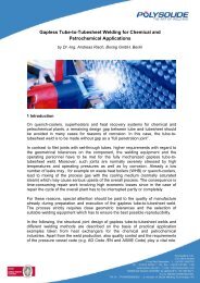
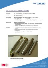
Figure 1<br />
Figure 1. Repair welding with orbital welding equipment on<br />
the primary circuit of a nuclear power plant: a branch pipe is<br />
reconditioned with internal cladding (stainless steel 316 L). The<br />
welding head is positioned on the inside of the piping and the weld<br />
is carried out via remote control. The welding head is equipped with<br />
an endoscope and the collector type welding head permits endless<br />
rotating.<br />
2 Focus on Nuclear Power Generation, Coverstory, January 2011<br />
Work pieces to be repaired are mostly characterised by severe<br />
signs of wear (cracks, hard spots, erosion, etc). The concerned<br />
base material must be removed by machining, after which it is<br />
replaced by cladding with filler metal of the same kind.<br />
The manufacturing of work pieces where cladding operations<br />
has been planned from the very beginning are usually carried<br />
out by means of fixed installations in the workshop (cladding<br />
to avoid corrosion or buttering to prepare welding of non<br />
homogeneous welds).<br />
Depending on the level of mechanisation and automation,<br />
these installations are suitable for the production of small lots<br />
or medium batches. In many cases, even heavy or voluminous<br />
work pieces can be moved or rotated, reducing the complexity<br />
of cladding operations.<br />
The restoring of undersized work pieces, e.g. caused by<br />
machining errors, can be carried out in a similar way by<br />
cladding, but in most cases automated welding is not possible<br />
due to a lack of adequate clamping devices.<br />
Diverse requirements<br />
The cited examples demonstrate the wide diversity of<br />
requirements to be satisfied by cladding processes. Some<br />
typical load types are listed below; often the work pieces are<br />
exposed to combinations of different stress patterns:<br />
• Corrosion or high-temperature corrosion in dry or wet<br />
environments<br />
• Different kinds of wear (abrasive, cavitation pitting, etc.)<br />
• Impact stress<br />
• Thermal shocks.<br />
The deposition of buffer layers has to be considered as a<br />
special application of cladding. The work piece should be<br />
protected against wear and eroded material replaced; the<br />
buttering process is used to prepare an intermetallic joint<br />
between two different metallic alloys to be welded. As the<br />
active forces absorbed by the joint are entirely effective at the<br />
buffer layer, reliable buttering quality is necessary. Generally,
the requirements for buffer layers are at the same level of<br />
quality demanded for welded joints; in many cases they can<br />
be met only by means of TIG hot wire welding. TIG hot wire<br />
cladding and buttering is therefore the most appropriate<br />
procedure for a wide range of applications.<br />
The fine grain structure of the deposited material, the evenly<br />
formed surface of the layers, the possibility to weld in all<br />
positions and the extraordinary flexibility of the process<br />
management are reasons to prefer TIG hot wire welding for<br />
delicate cladding applications.<br />
TIG welding allows precise control of the energy input<br />
released by the electric arc independently from the addition<br />
of filler wire, so work pieces with complex geometries or<br />
irregular shapes can be treated. There is also the possibility<br />
to deposit layers of different thicknesses, to vary welding<br />
parameters during ignition or downslope within wide limits<br />
etc.<br />
Melting rates<br />
TIG cladding processes can be kept stable at weld current<br />
intensities from about 80 A up to 450 A.<br />
The attainable melting rates start at a few hundred grams<br />
per hour and, if two synchronised torches are used, can be<br />
increased up to 2.5 kg/h or sometimes 3 kg/h.<br />
Additional functions such as Arc Voltage Control, oscillation,<br />
movements synchronized with the pulsed weld current etc.<br />
can be applied for TIG cladding processes without restriction;<br />
however, in cases where the highest melting rates are to be<br />
achieved, a strong constant weld current must be selected.<br />
In the case of cladding with the addition of dissimilar filler<br />
material the choice of weld parameters mainly depends on the<br />
following criteria:<br />
• Limitation of dilution of the deposit (attaining the required<br />
density of the layer while respecting the specified limits of<br />
the different constituents of the alloy)<br />
• Attaining the expected surface quality of the coating<br />
• Guaranteeing the promised melting rate (economy of the<br />
operation).<br />
To keep the dilution of the layers as low as possible the right<br />
order of weld beads and electrode positioning must be known<br />
and respected.<br />
The wire can added from either the front or the side. In this<br />
case it acts like a shield and protects the substrate against the<br />
direct effects from the arc; a more significant portion of the<br />
released energy is used to melt the filler material and only a<br />
smaller part remains to melt the base material.<br />
As already mentioned, the order of weld beads and electrode<br />
positioning are important parameters which can be exploited<br />
to decrease the degree of dilution. Similar to the method of<br />
using the wire as protection against the effects of the arc, an<br />
already deposited bead can serve in the same manner if the<br />
following bead is positioned with a significant overlay and only<br />
a small lasting contact zone with the substrate. The dilution<br />
mainly takes place between the existing and the new weld<br />
bead, so alloying with the basic material becomes significantly<br />
reduced. The result can be further improved if the electrode is<br />
positioned as much as possible above the existing weld bead.<br />
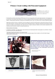
Figure 2. Mechanized welding equipment designed as a fixed<br />
installation in the workshop. Cladding of the inside of work pieces<br />
with nickel base alloy.<br />
Figure 2<br />
Wide range of torches<br />
The basic device of any cladding equipment is a TIG hot wire<br />
power source with a modular structured control centre which<br />
processes the entire movements of the different units.<br />
The software is especially adapted to the needs of programs<br />
for cladding operations. To cover various fields of application,<br />
differently designed torches are available. For the best choice of<br />
a torch the following criteria should be considered:<br />
• Work piece dimensions<br />
• Thermal conditions of the weld (with or without preheating)<br />
• Accessibility of the area to be treated<br />
• Shape of the work piece (bottom, cylinder, fillet, ...)<br />
• Welding positions<br />
A few of the numerous specially designed torches available<br />
include:<br />
• Torches with an automatically moving nozzle allow the<br />
modification of the protruding electrode during a cladding<br />
operation of e.g. cranks or sealing grooves, so the weld can<br />
be finished without interruption.<br />
• Two torches, mounted one behind the other on a welding<br />
lance, each equipped with two hot wire nozzles. These are<br />
used to produce a layer of two weld passes with only one<br />
passage of the lance inside a tube; this method is extremely<br />
economic.<br />
• Torches with integrated sensors to avoid the interruption of<br />
the weld at the front of the hole and continued as soon as its<br />
rear is reached.<br />
• Slim torches suitable for cladding of holes with diameters of<br />
less than 50 mm.<br />
• Torches with a motorised device to adjust their setting angle<br />
are used to weld continuously specific shapes such as an<br />
internal or external radius.<br />
Focus on Nuclear Power Generation, Coverstory, January 2011 3
Figure 3<br />
Figure 3. Buttering on a tube end of a steam generator in preparation<br />
for a non heterogeneous weld with an orbital welding equipment.<br />
(Average welding current 180 to 280 A, travel speed 250 to 450 mm/<br />
min., melting rate between 0.6 to 1.2 kg/h).<br />
Figure 4<br />
Figures 4. and 5 Examples of welding torches for cladding the inside<br />
of holes, straight or inclined models (single or double hot wire<br />
feeding), designed for weld current intensities up to 400 A.<br />
Figure 5<br />
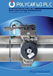
Figure 6<br />
Figure 6. An unlimited number of rotations and movement<br />
combinations between the collector welding head and the column &<br />
boom enable cladding operations of unusual geometries<br />
4 Focus on Nuclear Power Generation, Coverstory, January 2011<br />
To process work pieces which can be manoeuvred into a<br />
suitable welding position, the equipment can be completed<br />
with additional turntables, column and boom devices and roller<br />
blocks.<br />
Classic applications for cladding operations are the weld<br />
overlay of tank bottoms (in a flat position) and the coating of<br />
the inside or outside of vertically positioned cylindrical work<br />
pieces.<br />
Special equipment<br />
Special equipment has been developed for weld overlay inside<br />
long tubes (8 m to 12 m in length) with diameters above 220<br />
mm. Two torches, each with a double hot wire nozzle, are<br />
mounted one behind the other on the lance. The lance itself<br />
slides on ropes, and is moved to the rear end of the tube<br />
before the welding sequence commences.<br />
During the cladding operation the lance is pulled through the<br />
tube, thus creating the longitudinal movement of the welding<br />
tools. Two synchronised hot wire TIG sources control the<br />
longitudinal movement of the lance, the rotation of the tube<br />
and the intrinsic displacement of the torches, i.e. Arc Voltage<br />
Control and oscillation. In most cases these kinds of tubes<br />
are to be coated with nickel based alloys on the inside; a total<br />
layer thickness of 5 mm is usually requested.<br />
Cladding operations become more complicated if due to its<br />
weight, dimensions or geometry (boreholes in large work<br />
pieces or not axially symmetrical zones) the work piece<br />
cannot be moved. As this kind of problem occurs frequently,<br />
Polysoude offers a product line where the welding head can<br />
be rotated without twisting the associated supply cables.<br />
The welding heads are equipped with collectors, a technique<br />
which was originally developed for certain orbital welding<br />
applications.<br />
In extreme cases if complex parts of the work piece must<br />
be coated, the collector welding heads themselves can be<br />
mounted on slides and moved longitudinally or laterally.<br />
The superposition of the endless rotation of a collector<br />
welding head with the motions of associated slides increases<br />
the flexibility of the equipment substantially and opens access<br />
to a multitude of cladding applications.<br />
Polysoude supports those industries interested in this process<br />
and offers or develops cladding equipment which meets and<br />
often exceeds the demands of the respective customer. In<br />
so doing over the course of time a diverse range of standard<br />
equipment and special installations for various cladding<br />
purposes has been created.<br />
Whenever major focus is put on the quality of produced<br />
weld overlay coatings, the first choice would be the easily<br />
automated TIG hot wire cladding process. The TIG cladding<br />
process can offer competitive advantages over other high-<br />
performance welding methods. In cases involving complex<br />
work pieces, difficult environmental conditions or there is<br />
a general demand for the flexible use of equipment, it is<br />
recommended to thoroughly examine whether its application<br />
will offer technical and economical advantages.<br />
More interesting articles are to be found in the webshop at:<br />
http://webshop.kci-world.com