MegaGrow Greenhouse Manual - International Greenhouse Company
MegaGrow Greenhouse Manual - International Greenhouse Company
MegaGrow Greenhouse Manual - International Greenhouse Company

You also want an ePaper? Increase the reach of your titles
YUMPU automatically turns print PDFs into web optimized ePapers that Google loves.
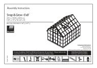
The <strong>MegaGrow</strong> 8ft Model<br />
<strong>Manual</strong><br />
<strong>International</strong> <strong>Greenhouse</strong> <strong>Company</strong><br />
1644 Georgetown Road, Danville, IL 61832<br />
TEL: (888)-281-9337 EMAIL: help@igcusa.com
WARRANTY<br />
10 YEAR GUARANTEE<br />
<strong>Greenhouse</strong> Megastore commitment to quality is priority No. 1<br />
Frame assembly<br />
We guarantee the frame of your greenhouse for ten years. If within that time a fault develops<br />
due to faulty workmanship or materials, just return the parts to <strong>Greenhouse</strong>megastore and we<br />
will replace the relevant parts free of charge.<br />
Polycarbonate twin wall glazing<br />
The polycarbonate (6mm) twin wall glazing includes a 10 year pro-rated warranty against<br />
yellowing and hazing. Polycarbonate provides a long service in the most severe climates and<br />
maintains its impact strength from –40F to 250F.<br />
IMPORTANT<br />
BEFORE BEGINNING ASSEMBLY<br />
Review your packing checklist before you start assembling your greenhouse kit. In the event that you find any<br />
missing items, please notify us immediately at 1-888-281-9337.<br />
TOOLS REQUIRED<br />
Electric drill with Phillips screwdriver bit.<br />
7/16 Hex Nut driver.<br />
7/16 open-end wrench.<br />
3/8 open-end wrench. (For door roller adjustment)<br />
Flat Head screwdriver. (To fit spring clips on door rollers)<br />
Phillips screwdriver. (To fix eve plates)<br />
Assembly time for two people is usually one day or about eight hours.<br />
HELPFUL ADVICE<br />
The greenhouse manual has been constructed using pictures and written instructions to make the assembly of<br />
the kit as painless as possible. For a trouble free assembly makes sure the foundation is flat and level.<br />
Stainless steel ¼-20 “T” bolts are used for the assembly. IMPORTANT: Make sure the correct number of<br />
“T” bolts are slotted into the aluminum frame parts as given in the instructions. The installation of missed bolts<br />
may require some disassembly.<br />
HINT: Use masking tape to hold bolts in approximate position while assembling the greenhouse kit.<br />
The glazing panels are UV coated on one side only, this side must face outward. The UV side is marked<br />
“THIS SIDE UP” Do not remove the protective covering until ready to install the panel into the frame. Failure<br />
to install the panels the correct side facing outward will void the warranty.<br />
All parts of the aluminum frame fit together easily, if a part appears not to fit verify you are using the<br />
correct part. Forcing a part into place will affect the integrity of the finished structure.<br />
If you have a problem with the assembly of this greenhouse kit help is just a phone call away,<br />
(1-888-281-9337) one of our staff will be pleased to help you get up and growing.
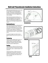
SELECTING A GREEN HOUSE SITE<br />
Locating a <strong>Greenhouse</strong>:<br />
The location of a greenhouse should be chosen very<br />
carefully. During the harsh winter months, the position of<br />
the greenhouse should receive at least six hours of direct<br />
sunlight. Shelter from high winds and from excessive<br />
water buildup should also be a consideration. Finding a<br />
location that is close to water and electricity and is also<br />
easily accessible from both home and garden, combined<br />
with the above considerations, should make for a very<br />
happy gardener.<br />
For best heat gain during the winter, an east-west position<br />
is the best choice, providing the maximum solar heat gain.<br />
Since the sun is much lower during the winter months,<br />
southern exposure might be restricted: In this case, simply<br />
turn the greenhouse to a position that will allow the<br />
maximum amount of winter sun to penetrate it.<br />
(See diagram upper right)<br />
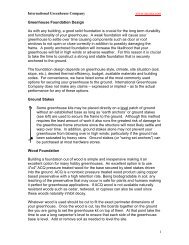
FOUNDATIONS:<br />
IT IS CRITICALLY IMPORTANT THAT FOUNDATIONS ARE SQUARE AND LEVEL.<br />
for the greenhouse To be assembled correctly and all parts to fit. There are a number of common types of<br />
greenhouse foundations used:-<br />
A poured concrete slab.<br />
A concrete foundation to frost line.<br />
Pressure treated lumber 4x 6<br />
Before you start check your local building code requirements.<br />
Recommendation<br />
Most <strong>MegaGrow</strong> greenhouses can be installed using 4” X 6” pressure treated lumber. This should be<br />
set on the 4” edge and buried to about 4” to 5” below ground level. The corners are fixed using 6” angle<br />
brackets. The additional weight of 4” X 6” over 4” X 4” should be adequate to hold the greenhouse<br />
down.<br />
If the greenhouse is to be positioned in a highly exposed area, it is recommended that the footings be<br />
pinned down using rebar (approx 1Ft from the corners). The holes need to be drilled at an angle of about<br />
45 degrees toward the center of the timber with the rebar driven down flush with the top of the timber.<br />
The inside floor of the greenhouse should be covered with pea gravel or crushed limestone. This stone<br />
will act as a storage heater, soaking up the heat of the sun during the day. This will reduce heating costs<br />
during the winter months.<br />
Concrete<br />
If the greenhouse is to be located on a concrete footing or slab, mount a 2’ X 4” wood plate to the<br />
surface of the concrete base. When using a concrete as a foundation it is important to consider drainage.
Side Assembly<br />
SECTION-1<br />
Tools Required: -7/16” Box Wrench.<br />
Side parts Pack<br />
(1) Side Cill (Item # 1).<br />
(1) Gutter (Item # 2).<br />
(2) Side Brace (Item # 4). NOTE:- The Side Brace is distinguishable from the<br />
end brace by its length . The side brace is the longer of the two.<br />
Glazing bars (For required number see chart ).<br />
ASSEMBLY<br />
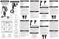
STEP-1 Lay out parts see (PIC-1) Gutter to the top cill at the bottom.<br />
STEP-2 Install “T” bolts in to gutter as (PIC-3) leve lose as shown.<br />
STEP-2 Assemble Glazing bars to the gutter section using bolts from (STEP-2).<br />
STEP-3 place “T” bolts into open end of glazing bar aprox ½” in from end<br />
(see PIC-4) and mount to cill using second hole in from the end, because<br />
this is the outside glazing bar place one end of the side brace onto the<br />
“T” bolt before installing the nut. Install all remaining G/bars repeat the<br />
procedure for the last G/bar using the remaining side brace, remember the<br />
inside face must face out.<br />
NOTE:- The inside face of the brace should face towards the end of the<br />
side wall.<br />
STEP-4 Secure the remaining (2) lose ends of the brace to the end slots in the gutter<br />
section using a ”T” bolt, this is to temporarily support the brace to stop<br />
damage until installing in (SECTION-4 Main assembly)<br />
NOTE:- DO NOT TIGHTEN BOLTS AT THIS TIME “ SNUG UP ONLY”.<br />
REPEAT ABOVE FOR THE SECOND SIDE.
Side Assembly<br />
PIC-1<br />
PIC-3<br />
PIC-2<br />
PIC-4
Back End Assembly<br />
SECTION-3<br />
Tools Required: -7/16” Box Wrench.<br />
Back End parts Pack<br />
(1) End Cill (Item # 6). (1) Rear R/H Corner Brace (Item # 15).<br />
(1) L/H Corner Leg (Item # 8). (1) Rear L/H Corner Brace (Item # 17).<br />
(1) R/H Corner Leg (Item # 7). (1) Rear Cross Brace (Item # 29SD).<br />
(1) L/H Corner Roof (Item # 10). (1) L/H Outer Glazing Bar (Item # 12).<br />
(1) R/H Corner Roof (Item # 9). (2) R/H Outer Glazing Bar (Item #11).<br />
(1) R/H Inner Glazing Bar (Item #13). (1) Ridge Gusset Plate (Item #24).<br />
(1) L/H Inner Glazing Bar (Item #14). (1) Leg Gusset Plate (Item #25).<br />
(<br />
ASSEMBLY<br />
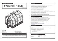
STEP-1 Lay out parts as in (PIC-1) Before starting assembly.<br />
STEP-2 Assemble glazing bars to the cill, with “T” bolts as shown in (PIC-1).<br />
Mount the (2) angle end braces to the cill, using the (3 rd ) hole in from each end as<br />
shown in (PIC-6).<br />
STEP-3 Insert (3) “T” bolts into each glazing bar from the top, (leave one bolt apox (½”)<br />
in from the end for connection To Corner Roof (Items #9&10).<br />
NOTE:- (1)“T” bolt placed in the (2) center bars are for the fan mounting bracket<br />
If unit has no fan, only place (2) “T” bolts in the center G/bars.<br />
STEP-4 Connect the (2) R/H glazing bars to the R/H Corner Roof bar (item #9).<br />
STEP-5 Assemble leg gusset plate as (PIC-4) Insert (1) “T” bolt into the horizontal and<br />
vertical slots as (PIC-2).Before connecting corner brace as (PIC-4) note the bolt slot<br />
in the center of the brace this should intersect with the slot in the outer G/bar.<br />
NOTE:- If the slot is not positioned over the G/bar you may have the wrong handed part.<br />
Use the lower “T” bolt in the outer G/bar for connecting the (2) parts.<br />
NOTE:- (PIC-4) also shows cross brace positioning.<br />
Repeat assembly to R/H side and ridge gusset plate assemble as leg gusset<br />
Remember to insert “T” bolts into the horizontal and vertical slots see (PIC-3).<br />
STEP-6 Install the cross brace to the leg gusset as shown in (PIC-4). Use the<br />
remaining “T” bolt in the (2) outside G/bars (if unit comes with fan use the (2)<br />
lower “T” bolts in the (2) center G/bars to secure in place. (See fan mounting<br />
for fan bracket positioning.
Back End Layout Assembly<br />
P-2<br />
P-3<br />
P-1<br />
P-4<br />
P-6<br />
P-5
Front end Assembly<br />
Front End parts Pack<br />
SECTION-3<br />
Tools Required: -7/16” Box Wrench<br />
(1) End Cill (Item # 6). (1) Door End Corner Brace (Item # 18).<br />
(1) L/H Corner Leg (Item # 8). (2) Door Side Brace (Item # 23).<br />
(1) R/H Corner Leg (Item # 7). (1) Door Header Bar (Item # 29).<br />
(1) L/H Corner Ridge (Item # 10). (1) Door End Center Glazing Bar (Item # 30).<br />
(1) R/H Corner Ridge (Item # 9). (2) Leg Gusset Plates (Item #22).<br />
(1) R/H Door Post (Item #21). (1) Ridge Gusset Plate (Item #24).<br />
(1) L/H Door Post (Item #22). (1) Mounting Bkt (Item #31).<br />
(1) Door Slide Assemble (Item #32-33). (1) R/H Door Slide End Mount Bkt (Item #34).<br />
(2) Slide End Cover (Item #36) (1) L/H Door Slide End Mount Bkt (Item #35)<br />
ASSEMBLY<br />
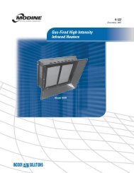
STEP-1 Lay out parts as in (PIC-1) Before starting assembly.<br />
STEP-2 Assemble door side post (Item#21&22) to the cill, with “T” bolts including the (2)<br />
corner braces using the (3 rd ) hole in on both sides. Connect the to corner legs to<br />
the outside holes in the cill as shown in (PIC-1).<br />
STEP-3 Insert (2) “T” bolts into each door side post(Item#21&22) from the top, (leave one<br />
bolt aprox (½”) in from the end for connection To Corner Roof (Items #9&10).<br />
NOTE:- (1)“T” bolt placed in the door post is for connection of the door side brace,<br />
move “T” bolt to aprox mid point in the door post.<br />
STEP-4 Connect the R/H door post (Item#21) to the R/H Corner Roof bar (item #9).<br />
STEP-5 Assemble leg gusset plate, Insert (1) “T” bolt into the horizontal and<br />
vertical slots as (PIC-2 Back assembly) add (1) additional “T” bolt in the horizontal<br />
slot of the corner leg , this is for the connection of the door side brace.<br />
Repeat (steps 4&5) for assembly to R/H side. Assemble ridge gusset plate as leg gusset<br />
Remember to insert “T” bolts into the horizontal and vertical slots see (PIC-3)<br />
Back assembly . Install the (2) door side brace(Item#23).<br />
STEP-6 Insert (4) “T” bolts into the door slide center G/bar move (2) “T” bolts to aprox<br />
center of the G/bar, (leave one bolt aprox (½”) in from each end for connection To Corner<br />
Roof (Items #9&10). Connect slide in place to the (2) corner roof sections.<br />
Install center G/bar to center hole in the ridge plat and using the (3) hole bracket<br />
connect to the center of the door slide as (PIC-2).<br />
NOTE:- The (2) ¾” angle sections remaining are not used at this time put to one side<br />
Until final assembly of the doors.
Front End Assembly<br />
P-4<br />
P-3<br />
P-2A<br />
P-<br />
P-1 P-2
Main frame Assembly<br />
SECTION-4<br />
Tools Required: -7/16” Box Wrench.<br />
7/16” Open Wrench.<br />
Side parts Pack<br />
(1) Ridge bar (Item # 3).<br />
(2 per vent ) Mounting Bkt (Item #31).<br />
Glazing bars (Item #5) (For required number see chart ).<br />
ASSEMBLY<br />
STEP-1 Position sides and end assembly’s around the foundation for final assembly.<br />
STEP-2 Start by positioning the back assembly and one side assembly on the foundation.<br />
Fit the back corner leg onto the “T” bolt on the end of the side cill. See (PIC’s-1&2).<br />
Mount the gutter between the top of the leg and corner ridge bar as (PIC’s-3&4).<br />
Slide remaining (2) bolts from the top of the leg and bottom of ridge corners into the<br />
slots and secure.<br />
NOTE:-As in (PIC-4) both corners bars MUST butt up to the gutter bar.<br />
STEP-3 Repeat step-(2) on remaining (30 corners.<br />
STEP-4 Fit the ridge bar into top of ridge corner bars as (PIC’s 6&7). Use remaining (2) bolts to<br />
secure as (PIC-6) both ends.<br />
STEP-5 Measure across the front end from the out side at the bottom of the legs, and then at the top<br />
of the legs. The two readings should be within 1/8”. Repeat at the back. If the readings are<br />
not within tolerance, first check the top leg joints, and ridge joints for gap. If the joints are<br />
ok then the angle of the ridge will need to be adjusted. Adjusting the ridge up will reduce<br />
the top leg dimension. Lowering the ridge will increase the dimension.<br />
To adjust the ridge high slacken all bolts holding the (2) leg gussets, ridge gusset (if rear end<br />
Is to be adjusted then ) all glazing bars. (if front end is to be adjusted then) door post and<br />
door header. Have a second person or use a 2x4 to reposition the ridge and snug the bolts.
Main Frame Assembly<br />
PIC-1<br />
PIC-2<br />
PIC-3<br />
PIC-4<br />
PIC-6<br />
PIC-5<br />
PIC-7
Roof &Vent Assembly<br />
SECTION-5<br />
Tools Required: -7/16” Box Wrench.<br />
Screw drivers X & flat end.<br />
Vent kit (Parts Per Kit)<br />
(1) Vent Latch Plate (Item #38).<br />
(2) Vent side bars (Item # 39).<br />
(1) Vent Hinge Bar (Item # 40).<br />
(1) Vent fixed Latch Plate (Item #41).<br />
(2) Mounting Bkt’s (Item #31).<br />
(1) Vent eve retaining plate (Item # 37).<br />
(2) Vent stops (Item #16).<br />
ASSEMBLY<br />
STEP-1 Start the assembly of the frame install “T” bolt into the hinge bar<br />
(insert “T” bolt from the side flanged side see (PIC-5). Fit “T” bolts into<br />
latch plate the head of the bolt on the small flange side Assemble vent<br />
frame as (PIC-2) with side bars.<br />
NOTE:-In (PIC-2) the vent opener is shown with the channel facing up.<br />
STEP-2 Install glazing seal down the (2) side bars and along the small flange on<br />
The latch plate.<br />
STEP-3 install the glazing panel using glazing clips as shown in (Section-6, PIC-3)<br />
With the eve retaining plate fitted on the open end of the glazing panel.<br />
NOTE:-Fit first clip aprox (2) inches in at the eve plate end.<br />
NOTE:-The glazing panel is sealed on (1) end only, the sealed end fits into<br />
the hinged frame section.<br />
STEP-4 Turn the vent over and install latch using screws provided in bag. Orientation<br />
Of the latch in (PIC-2) you see inside of the latch.<br />
STEP-5 Install the vent into the hinge channel as shown in (PIC-6). Slide the vent<br />
Along the ridge and centralize over the two glazing bars(Vent should seat,<br />
without the (2) top frame nuts contacting the glazing bars) in required<br />
position.<br />
STEP-5 Install (2) “T” bolts into each glazing bar slide “T” bolts up to the vent<br />
Fit (1) mounting bracket to each side, install the fixed latch plate (Item#41).
Roof Vent Assembly<br />
PIC-1<br />
PIC-2<br />
PIC-3<br />
PIC-4<br />
PIC-5<br />
PIC-6
Roof Vent Assembly
Glazing Assembly<br />
SECTION-6<br />
Tools Required: -Drill with s/driver bit.<br />
Sharp knife.<br />
Side parts Pack<br />
** Glazing Seal (Item #P1). ** Eve Retaining plate (Item #26).<br />
** Glazing Clips (Item # P2) . ** Cill retainer (Item #27).<br />
** Screw s/drill #10-5/8” (Item #P5).<br />
GLAZING PANELS<br />
** Side & Roof (Item # 58). (1) R/H Top door end panel (Item # 52).<br />
** Vent Lower panel (Item #48). (1) L/H Top door end panel (Item #53).<br />
** Vent panel (Item #49). (1) R/H Outer back panel (Item #54).<br />
(1) R/H front door side panel (Item # 50). (1) L/H Outer back panel (Item #55).<br />
(1) L/H Front door side panel (Item #51). (1) R/H Inner back panel (Item #56).<br />
(1) Center back panel (Item #59). (1) L/H Inner back panel (Item #57).<br />
** For Required Number See List.<br />
ASSEMBLY<br />
STEP-1 Start on the outside of the back end attach glazing seal on the corner ridge bar from the<br />
top of the ridge down to the corner leg see (PIC-1), complete this on both sides.<br />
Place seal down the (2) legs and on both sides of the glazing bars.<br />
NOTE:- When glazing is installed seal will be across the top and down both sides. There is no<br />
seal along the cill.<br />
Once seal is complete on the back repeat for the front end.<br />
For the wall and roof panels place tape down the (2) sides only.<br />
For the lower vent panel tape across the fixed latch plate and down the (2) sides.<br />
STEP-2 Install the glazing start at the back end install the center panel first ( If installing the fan<br />
See SECTION-8) work from center out using glazing clips space apox 12-15 inches apart<br />
See (PIC-3). Repeat on the front end.<br />
NOTE:-Glazing will help square the frame as it is installed, adjust the framing as required.<br />
STEP-3 Install eve retaining plate to the end without aluminum tape of roof panels by sliding into<br />
the slot on the back of the eve retaining plate, place the panel in position holding the panel<br />
aprox 12” above the gutter slide the panel up into the ridge section lower panel into small<br />
recess in the back of the gutter section and secure with glazing clips. As with the vent place<br />
first set of clips down near to eve retaining plate to secure in place (PIC-4).<br />
STEP-4<br />
Install side wall panels place top of panel under gutter and slide into place and secure with<br />
glazing clips.<br />
STEP-5 install cill retaining plates around the bottom of panels. Place retainer up against glazing and<br />
secure using 5/8” self drilling screws (PIC-5).<br />
NOTE:- DO NOT REMOVE the protective cover from the glazing panels until You are ready to<br />
Install. THE PANELS HAVE BEEN TREATED WITH A UV PROTECTIVE TO STOP<br />
DISCOLORATION ON ONE SIDE. THIS SIDE MUST FACE OUT.
Glazing Assembly<br />
PIC-1<br />
PIC-2<br />
PIC-3<br />
PIC-4<br />
PIC-5
SCREEN DOOR SUPLIMENTAL<br />
INFORMATION