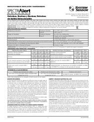
4-Wire Photoelectric Duct Smoke Detector
4-Wire Photoelectric Duct Smoke Detector
4-Wire Photoelectric Duct Smoke Detector

You also want an ePaper? Increase the reach of your titles
YUMPU automatically turns print PDFs into web optimized ePapers that Google loves.
Wiring for 4-wire <strong>Duct</strong> <strong>Smoke</strong> <strong>Detector</strong> and Accessories<br />
POWER INPUTS (NOTE 1) POWER INPUTS (NOTE 1)<br />
24VAC/DC<br />
120<br />
VAC<br />
24V<br />
120<br />
VAC<br />
9 10<br />
9 10<br />
OR<br />
AUXILIARY CONTACTS<br />
FOR FAN SHUTDOWN, ETC. (NOTE 2)<br />
AUX A<br />
AUX B<br />
N.C. C. N.O. N.C. C. N.O.<br />
AUXILIARY CONTACTS<br />
FOR FAN SHUTDOWN, ETC. (NOTE 2)<br />
N.C.<br />
AUX A<br />
C.<br />
N.O.<br />
OR<br />
AUX B<br />
N.C. C.<br />
N.O.<br />
16 6 17 8 18 7<br />
16 6 17 8 18 7<br />
SUPERVISORY CONTACTS<br />
(NOTE 3)<br />
SUPERVISORY CONTACTS<br />
(NOTE 3)<br />
SUP C. SUP N.O. SUP C.<br />
SUP N.O.<br />
EOL RESISTOR<br />
SPECIFIED BY<br />
PANEL<br />
MANUFACTURER<br />
UL/FM LISTED<br />
4-WIRE<br />
CONTROL PANEL<br />
+<br />
3 14 3<br />
14<br />
ALARM<br />
INITIATION<br />
LOOP<br />
ALARM<br />
INITIATION<br />
CONTACTS<br />
(NOTE 4)<br />
4<br />
5<br />
ALARM C.<br />
ALARM N.O.<br />
ALARM<br />
INITIATION<br />
CONTACTS<br />
(NOTE 4)<br />
4<br />
5<br />
ALARM C.<br />
ALARM N.O.<br />
FIRST DETECTOR IN THE LOOP<br />
LAST DETECTOR IN THE LOOP<br />
NOTE 1: 24V Power Inputs accept a non-polarized 24VDC or 24VAC 50-60Hz.<br />
120VAC Power Inputs accept only 120VAC 50-60Hz. Connect power<br />
source to appropriate terminals of each detector. See specifications<br />
for additional power supply information.<br />
NOTE 2: Auxiliary contacts shown in standby position. Contacts switch<br />
during alarm as indicated by arrows. Auxiliary contacts are not to<br />
be used for connection to the control panel. See specifications for<br />
contact ratings.<br />
NOTE 3: Supervisory contacts shown in standby position. Open contacts<br />
indicate a trouble condition to the panel. See specifications for<br />
contact ratings.<br />
NOTE 4: Alarm Initiation contacts shown in standby position. Closed<br />
contacts indicate an alarm condition to the panel. See specifications<br />
for contact ratings.<br />
*Please refer to the corresponding installation manual for accessory wiring diagrams.<br />
Important Notes on 2:1 Sensor-to-Power Capability<br />
• 2:1 sensor-to-power capability is not available for all InnovairFlex models. The feature is only available on the D4120 4-wire conventional models.<br />
• 2:1 sensor-to-power capability can be enabled using one D4120 and one D4S, or two D4S and one D4P120.<br />
Important Interconnect Notes<br />
• When using the interconnect feature, all interconnected units must be powered using the same independent supply.<br />
• Polarity must be maintained throughout the interconnect wiring. Connect the INT+ terminal on unit 1 to the INT+ terminal on unit 2 and so on. Similarly,<br />
connect the INT/AUX– terminal on unit 1 to the INT/AUX- terminal on unit 2 and so on.<br />
• Up to 50 D4120 units, 50 D4P120 units, or 50 units of combination may be interconnected.<br />
• Up to 10 DH100ACDC units may be interconnected. Please note that each of the 9 DH100ACDC units interconnected may be replaced by three D4P120<br />
units. Therefore, when using the interconnect feature a single DH100ACDC can drive either 9 DH100ACDCs or 27 D4120 units.<br />
* NOTE: Alarm can be reset only at the initiating device and not at the devices interconnected.<br />
A05-0419-000