2151/2151T Low Profile Photoelectronic Plug-in Smoke Detectors
2151/2151T Low Profile Photoelectronic Plug-in Smoke Detectors
2151/2151T Low Profile Photoelectronic Plug-in Smoke Detectors

You also want an ePaper? Increase the reach of your titles
YUMPU automatically turns print PDFs into web optimized ePapers that Google loves.
INSTALLATION AND MAINTENANCE INSTRUCTIONS<br />
<strong>2151</strong>/<strong>2151</strong>T <strong>Low</strong> <strong>Profile</strong><br />
<strong>Photoelectronic</strong> <strong>Plug</strong>-<strong>in</strong><br />
<strong>Smoke</strong> <strong>Detectors</strong><br />
3825 Ohio Avenue, St. Charles, Ill<strong>in</strong>ois 60174<br />
1-800-SENSOR2, FAX: 630-377-6495<br />
www.systemsensor.com<br />
Specifications<br />
Size<br />
Height:<br />
Diameter:<br />
Before Install<strong>in</strong>g<br />
Please thoroughly read the System Sensor manual A05-<br />
1003, Applications Guide for System <strong>Smoke</strong> <strong>Detectors</strong>,<br />
which provides detailed <strong>in</strong>formation on detector spac<strong>in</strong>g,<br />
placement, zon<strong>in</strong>g, wir<strong>in</strong>g, and special applications. Copies<br />
of this manual are available from System Sensor.<br />
NOTICE: This manual should be left with the owner/user<br />
of this equipment.<br />
IMPORTANT: The detector must be tested and ma<strong>in</strong>ta<strong>in</strong>ed<br />
regularly follow<strong>in</strong>g NFPA 72 requirements. The detector<br />
should be cleaned at least once a year.<br />
General Description<br />
The <strong>2151</strong> low-profile photoelectronic detector uses a stateof-the-art<br />
optical sens<strong>in</strong>g chamber. This detector is designed<br />
to provide open area protection and to be used with<br />
compatible UL listed control panels only. The capability of<br />
plugg<strong>in</strong>g this detector <strong>in</strong>to a variety of special bases makes<br />
it more versatile than equivalent direct-wired models.<br />
Two LEDs on each detector provide local 360° visible alarm<br />
<strong>in</strong>dication. They flash every five seconds <strong>in</strong>dicat<strong>in</strong>g that<br />
power is applied and the detector is work<strong>in</strong>g properly. The<br />
LEDs latch on <strong>in</strong> alarm. Remote LED annunciator capability<br />
is standard and may be implemented through an optional<br />
accessory RA400Z. The alarm can be reset only by a momentary<br />
power <strong>in</strong>terruption. This detector may be tested<br />
by activat<strong>in</strong>g the <strong>in</strong>ternal reed switch with a magnet.<br />
Base Selection And Wir<strong>in</strong>g Guide<br />
Refer to the <strong>in</strong>stallation <strong>in</strong>structions for the <strong>Plug</strong>-<strong>in</strong> Detector<br />
Bases for base selection and wir<strong>in</strong>g <strong>in</strong>structions. System<br />
Sensor has a variety of detector bases available for<br />
this smoke detector, <strong>in</strong>clud<strong>in</strong>g 2-wire applications with and<br />
without relays and/or current limit<strong>in</strong>g resistors, 4-wire and<br />
120VAC applications.<br />
2.0 <strong>in</strong>ches (51 mm) <strong>in</strong>stalled <strong>in</strong> B401 Base<br />
4.1 <strong>in</strong>ches (104 mm) <strong>in</strong>stalled <strong>in</strong> B401 Base<br />
6.1 <strong>in</strong>ches (155 mm) <strong>in</strong>stalled <strong>in</strong> B110LP Base<br />
Weight: 3.1 oz. (88 g)<br />
Operat<strong>in</strong>g Temperature Range: 0°C to 49°C (32°F to 120°F); <strong>2151</strong><br />
0°C to 38°C (32°F to 100°F); <strong>2151</strong>T<br />
Operat<strong>in</strong>g Humidity Range:<br />
10% to 93% Relative Humidity noncondens<strong>in</strong>g<br />
Heat Sensor (<strong>2151</strong>T only):<br />
135°F Fixed Temperature Electronic Thermistor<br />
Latch<strong>in</strong>g Alarm:<br />
Reset by momentary power <strong>in</strong>terruption.<br />
All bases are provided with screw term<strong>in</strong>als for power,<br />
ground, remote annunciator connections and relay contact<br />
connections, if applicable. The electrical rat<strong>in</strong>gs for each<br />
detector-base comb<strong>in</strong>ation are also <strong>in</strong>cluded <strong>in</strong> the base <strong>in</strong>stallation<br />
<strong>in</strong>structions.<br />
Installation<br />
NOTE: All wir<strong>in</strong>g must conform to applicable local codes,<br />
ord<strong>in</strong>ances, and regulations.<br />
NOTE: Verify that all detector bases are <strong>in</strong>stalled, that<br />
the <strong>in</strong>itiat<strong>in</strong>g-device circuits have been tested, and that<br />
the wir<strong>in</strong>g is correct. (Refer to detector base manual for<br />
test<strong>in</strong>g procedure.)<br />
WARNING<br />
Remove power from <strong>in</strong>itiat<strong>in</strong>g-device circuits before <strong>in</strong>stall<strong>in</strong>g<br />
detectors.<br />
1. Install detectors:<br />
a. Place the detector <strong>in</strong>to the detector base.<br />
b. Turn the detector clockwise until the detector drops<br />
<strong>in</strong>to place.<br />
c. Cont<strong>in</strong>ue turn<strong>in</strong>g detector clockwise to lock it <strong>in</strong> place.<br />
2. Tamper Resistance: The detector bases can be made<br />
tamper resistant. When capability is enabled, detectors<br />
cannot be removed from the base without the use of a<br />
tool. See the detector base <strong>in</strong>stallation manual of the<br />
detector base for details <strong>in</strong> us<strong>in</strong>g this capability.<br />
3. After all detectors have been <strong>in</strong>stalled, apply power to<br />
the control unit.<br />
4. Test the detector us<strong>in</strong>g the magnet as described under<br />
TESTING.<br />
5. Reset the detector at the system control panel.<br />
6. Notify the proper authorities that the system is back on l<strong>in</strong>e.<br />
D100-101-00 1 I56-2806-001R
CAUTION<br />
Dust covers are an effective way to limit the entry of dust<br />
<strong>in</strong>to smoke detector sens<strong>in</strong>g chambers. However, they may<br />
not completely prevent airborne dust particles from enter<strong>in</strong>g<br />
the detector. Therefore, System Sensor recommends the<br />
removal of detectors before beg<strong>in</strong>n<strong>in</strong>g construction or other<br />
dust produc<strong>in</strong>g activity.<br />
Be sure to remove the dust covers from any sensors that<br />
were left <strong>in</strong> place dur<strong>in</strong>g construction as part of return<strong>in</strong>g<br />
the system to service.<br />
CAUTION<br />
<strong>Smoke</strong> detectors are not to be used with detector guards<br />
unless the comb<strong>in</strong>ation has been evaluated and found<br />
suitable for that purpose.<br />
Test<strong>in</strong>g<br />
Before test<strong>in</strong>g, notify the proper authorities that the smoke<br />
detector system is undergo<strong>in</strong>g ma<strong>in</strong>tenance and will temporarily<br />
be out of service. Disable the zone or system undergo<strong>in</strong>g<br />
ma<strong>in</strong>tenance to prevent unwanted alarms. <strong>Detectors</strong><br />
must be tested after <strong>in</strong>stallation and as part of periodic<br />
ma<strong>in</strong>tenance. Test <strong>2151</strong> and <strong>2151</strong>T as follows:<br />
NOTE: Before test<strong>in</strong>g the detector, check to ensure the<br />
LEDs bl<strong>in</strong>k. If they do not, the detector has lost power<br />
(check the wir<strong>in</strong>g) or it is defective (return it for repair).<br />
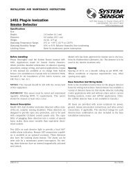
A. Test Magnet (p/n M02-04-01 or M02-09-00)<br />
1. Place the magnet aga<strong>in</strong>st the cover <strong>in</strong> the location<br />
designated by the raised mark to activate the test feature<br />
(see Figure 1).<br />
2. The LEDs should latch ON with<strong>in</strong> 5 seconds <strong>in</strong>dicat<strong>in</strong>g<br />
alarm and annunciat<strong>in</strong>g the panel.<br />
B. Aerosol Generator (Gem<strong>in</strong>i 501)<br />
Set the generator to represent 4% to 5%/ft. obscuration<br />
as described <strong>in</strong> the Gem<strong>in</strong>i 501 Manual. Us<strong>in</strong>g the bowlshaped<br />
applicator, apply aerosol until unit alarms.<br />
C. Direct Heat Method (Hair Dryer of 1000-1500 watts) <strong>2151</strong>T only<br />
A hair dryer of 1000-1500 watts should be used to test<br />
the thermistors. Direct the heat toward either of the two<br />
thermistors, hold<strong>in</strong>g the heat source approximately 12<br />
<strong>in</strong>ches from the detector <strong>in</strong> order to avoid damag<strong>in</strong>g the<br />
plastic hous<strong>in</strong>g. The detector will reset only after it has<br />
had sufficient time to cool. Make sure both thermistors<br />
are tested <strong>in</strong>dividually.<br />
Notify the proper authorities that the system is back on l<strong>in</strong>e.<br />
<strong>Detectors</strong> that fail these tests should be cleaned as described<br />
under MAINTENANCE and retested. If the detectors still<br />
fail these tests, they should be returned for repair.<br />
Clean<strong>in</strong>g<br />
Before remov<strong>in</strong>g the detector, notify the proper authorities<br />
that the smoke detector system is undergo<strong>in</strong>g ma<strong>in</strong>tenance<br />
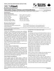
Figure 1. Bottom and side views show<strong>in</strong>g position of test magnet:<br />
Magnet Test<br />
Marker<br />
Test Magnet<br />
Position<br />
LED Status<br />
Indicators<br />
C0145-00<br />
Magnet Test<br />
Marker<br />
Test Magnet<br />
Position<br />
D100-101-00 2 I56-2806-001R
and will be temporarily out of service. Disable the zone or system<br />
undergo<strong>in</strong>g ma<strong>in</strong>tenance to prevent unwanted alarms.<br />
1. Remove the sensor to be cleaned from the system.<br />
2. Remove the sensor cover by press<strong>in</strong>g firmly on each of<br />
the four removal tabs that hold the cover <strong>in</strong> place.<br />
3. Vacuum the screen carefully without remov<strong>in</strong>g it.<br />
If further clean<strong>in</strong>g is required cont<strong>in</strong>ue with Step 4, otherwise<br />
skip to Step 7.<br />
4. Remove the chamber cover/screen assembly by pull<strong>in</strong>g<br />
it straight out.<br />
5. Use a vacuum cleaner or compressed air to remove dust<br />
and debris from the sens<strong>in</strong>g chamber.<br />
6. Re<strong>in</strong>stall the chamber cover/screen assembly by slid<strong>in</strong>g<br />
the edge over the sens<strong>in</strong>g chamber. Turn until it is<br />
firmly <strong>in</strong> place.<br />
7. Replace the cover us<strong>in</strong>g the LEDs to align the cover and<br />
then gently push<strong>in</strong>g it until it locks <strong>in</strong>to place. Make<br />
sure that the thermistors do not become bent under the<br />
cover on <strong>2151</strong>T.<br />
8. Re<strong>in</strong>stall the detector.<br />
9. Test the detector as described <strong>in</strong> TESTING.<br />
10. Reconnect disabled circuits.<br />
11. Notify the proper authorities that the system is back on l<strong>in</strong>e.<br />
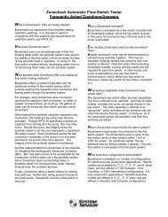
Figure 2:<br />
Optional<br />
Thermistors<br />
(<strong>2151</strong>T only)<br />
Cover<br />
Removal<br />
Tabs<br />
Sensor<br />
Cover<br />
Sens<strong>in</strong>g<br />
Chamber<br />
Cover and<br />
Screen<br />
Sens<strong>in</strong>g<br />
Chamber<br />
C0892-00<br />
Special Note Regard<strong>in</strong>g <strong>Smoke</strong> Detector Guards<br />
<strong>Smoke</strong> detectors are not to be used with detector guards<br />
unless the comb<strong>in</strong>ation has been evaluated and found<br />
suitable for that purpose.<br />
D100-101-00 3 I56-2806-001R
Please refer to <strong>in</strong>sert for the Limitations of Fire Alarm Systems<br />
System Sensor warrants its enclosed smoke detector to be free from defects <strong>in</strong> materials<br />
and workmanship under normal use and service for a period of three years<br />
from date of manufacture. System Sensor makes no other express warranty for this<br />
smoke detector. No agent, representative, dealer, or employee of the Company has<br />
the authority to <strong>in</strong>crease or alter the obligations or limitations of this Warranty. The<br />
Company’s obligation of this Warranty shall be limited to the repair or replacement<br />
of any part of the smoke detector which is found to be defective <strong>in</strong> materials or<br />
workmanship under normal use and service dur<strong>in</strong>g the three year period commenc<strong>in</strong>g<br />
with the date of manufacture. After phon<strong>in</strong>g System Sensor’s toll free number<br />
800-SENSOR2 (736-7672) for a Return Authorization number, send defective units<br />
Three-Year Limited Warranty<br />
postage prepaid to: System Sensor, Repair Department, RA #__________, 3825 Ohio<br />
Avenue, St. Charles, IL 60174. Please <strong>in</strong>clude a note describ<strong>in</strong>g the malfunction and<br />
suspected cause of failure. The Company shall not be obligated to repair or replace<br />
units which are found to be defective because of damage, unreasonable use, modifications,<br />
or alterations occurr<strong>in</strong>g after the date of manufacture. In no case shall the<br />
Company be liable for any consequential or <strong>in</strong>cidental damages for breach of this or<br />
any other Warranty, expressed or implied whatsoever, even if the loss or damage is<br />
caused by the Company’s negligence or fault. Some states do not allow the exclusion<br />
or limitation of <strong>in</strong>cidental or consequential damages, so the above limitation or<br />
exclusion may not apply to you. This Warranty gives you specific legal rights, and<br />
you may also have other rights which vary from state to state.<br />
D100-101-00 4 I56-2806-001R<br />
©2006 System Sensor