Studer D21m I/O System Components - ATT Audio Controls
Studer D21m I/O System Components - ATT Audio Controls
Studer D21m I/O System Components - ATT Audio Controls

You also want an ePaper? Increase the reach of your titles
YUMPU automatically turns print PDFs into web optimized ePapers that Google loves.
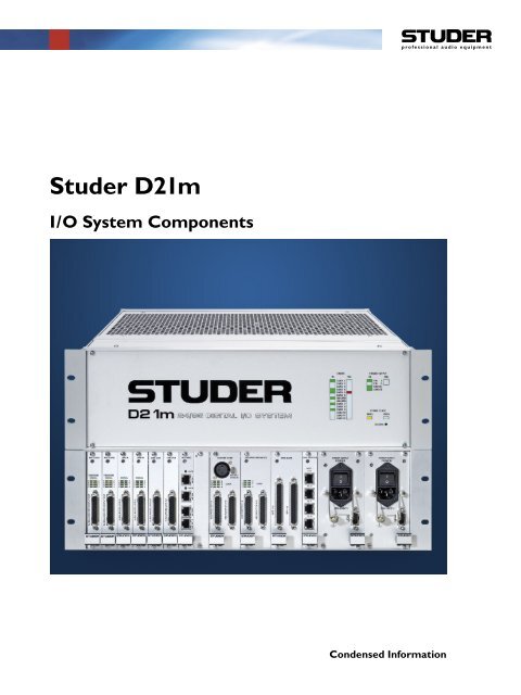
<strong>Studer</strong> <strong>D21m</strong>I/O <strong>System</strong> <strong>Components</strong>Condensed Information
The <strong>D21m</strong> I/O <strong>System</strong>The <strong>D21m</strong> I/O system provides very cost-effective inputsand outputs with maximum flexibility while maintainingthe well-known <strong>Studer</strong> sound quality. It is the first <strong>Studer</strong>I/O system providing full 96 kHz operation. Different I/Omodules can be plugged into a frame, providing I/Osystems tailor made to customers needs. And all thiscomes with an unequalled form factor. Full redundancyis available on power supplies as well as I/O links.<strong>System</strong> PhilosophyWhen using the <strong>D21m</strong> I/O system the DSP core itselfdoes not provide I/O, but is connected to the first <strong>D21m</strong>frame within the system (acting as a hub) by using<strong>Studer</strong> proprietary “HD Link” technology. On the coreside the connection is made to PE<strong>D21m</strong> cards. Theseare standard processing cards with additional linkingcapabilities. This link distance is limited to 10 m, so thefirst I/O box should be located close to the DSP core.From that frame it is possible to run optical-fiber MADIlinks to multiple places, up to several kilometers away.By using this “star” architecture it is ensured that a possibleproblem with one of the remote I/O boxes will notlead to a general breakdown of the whole I/O system. Amaximum of six remote I/O boxes (stage boxes) may beconnected to one hub frame. In case more I/O channelsshould be required it is possible to have multiples of the“local frames” (hubs) within the system.<strong>D21m</strong> Remote IO <strong>D21m</strong> Remote IO <strong>D21m</strong> Remote IOMADI<strong>D21m</strong> Hub & IOMADIMADIRS422 Link to DeskRedundancy issues are regarded as highly important. Itis therefore possible to run any MADI links with redundantcables. The system is automatically switching to theredundant connection, in case the primary connectionshould fail. For 96 kHz operation it is possible to use thesecond link as a channel count extension, transferringa total of 64 MADI channels even at 96 kHz samplingfrequency. The “redundant” MADI link may also be usedfor sharing an I/O box between two consoles.The MADI link between the first <strong>D21m</strong> frame (hub) andthe remote I/O boxes in addition carries all controlsignals needed to control the microphone amplifiercards, to interrogate the state (health) of any remoteI/O card and to display it within the console’s systemsurveyor page. This is without sacrificing any audio channelswithin the MADI link. Additionally, it is possible to“tunnel” an RS422 signal through the MADI connection.In this way it is possible to e.g. connect a MIDI device tothe remote I/O box and find the “extension” connectoron the hub frame next to the core again.Notes: Unlike the <strong>Studer</strong> D19m I/O system, the <strong>D21m</strong>system is engineered as an I/O system for use togetherwith a <strong>Studer</strong> digital console. Using the <strong>D21m</strong> systemas a “standalone” analog-to-digital or digital-to-analogconverter is only possible if MADI I/O is used on thedigital side. It is e.g. not possible to insert a AES/EBUcard and a Line In card and get the A/D-convertedsignal out of the AES/EBU card directly. This is onlypossible if the audio is routed with a DSP core. Sincethe MADI signal to the <strong>D21m</strong> remote I/O box is usedto synchronize the unit, a stable, low-jitter MADI signalis necessary in order to reach maximum audio quality.This is guaranteed by <strong>Studer</strong> equipment.PerformaDSP Core<strong>Studer</strong> Proprietary HD LinkIt is however possible to interconnect two I/O boxesusing MADI, whereby one of them must be switched to“Master” mode. In such a case up to 64 audio channelsmay be transmitted between two frames (applicable forMADI HD cards 1.949.411.23, 1.949.413.22, 1.949.414.20or newer). This mode is often referred to as “DigitalSnake”.
RS422 from Desk for SurveyorInformation and Mic ControlApplication: Full-Size <strong>System</strong>RemoteI/O BoxesI/O frame with DifferentRemote I/O Box 1 ... Types of I/O Cards... Remote I/O Box 5. . . .0...64 Ch MADI0...64 Ch MADIHub 1(and I/O)RS422 from Desk for SurveyorInformation and Mic ControlRS422 from Desk for SurveyorInformation and Mic Control4...6 AES/EBU Outputsto Monitoring Frame96 Ch In48 Ch Out96 Ch In48 Ch Out96 Ch In48 Ch Out96 Ch In48 Ch Out<strong>Studer</strong> Proprietary HD Link(max. Distance 10 m)DSP Core(PE andPE<strong>D21m</strong>Cards96 Ch In48 Ch Out96 Ch In48 Ch Out96 Ch In48 Ch Out96 Ch In48 Ch OutHub 2(and I/O)RS422 from Desk for SurveyorInformation and Mic Control0...64 Ch MADI0...64 Ch MADIRemoteI/O Boxes. . . .Remote I/O Box 6 ... ... Remote I/O Box 11Both the remote I/O box and the local hub frames arestandard <strong>D21m</strong> frames, providing the possibility to insertany I/O card available for the <strong>D21m</strong> I/O system. Thehub frame may therefore also be used for any audioI/O located close to the DSP core.Up to 6 remote I/O boxes can be connected per hubframe, except in the first hub frame, where one slot isoccupied for an AES/EBU card in order to provide I/Ofor monitoring and talkback of the Vista desk.The RS422 link for the second hub may be taken fromthe Vista desk by using a further RS422 port.The channel count of the MADI link may be adjustedusing card-internal DIP switches in steps of eight channels.In order to provide synchronization and surveyorinformation it is necessary to provide a MADI link toand from the remote I/O boxes at all times, even if thechannel count should be set to 0.The protocol switch on the front panel of the MADI I/Ocard may be set to “64 channel” to allow maximumusage of the available channels. This switch may onlyhave to be set to “56 channel” protocol for operationwith third-party MADI devices (in case no remote I/Obox is connected to the MADI I/O card).If 64 channels of MADI transmission are required whenworking at 96 kHz, the redundant MADI line can be usedas a “channel extension” for transmitting the MADI channels33-64 (29-56). This must be set accordingly with aDIP switch on the MADI I/O card inserted inthe hub frame.
INCARDSCARD 1CARD 2CARD 3CARD 4CARD 5CARD 6HD CARDHD CARDCARD 7CARD 8CARD 9CARD 10CARD 11CARD 12FAILPOWER SUPPLYINFAILPRI 1PRI 2DIGITALANALOGSYSTEM CLOCK96kHz48kHzRECONFIGApplication: Shared I/OInput Switchon Front Panel ofMADI HD Cardredundant1 2Remote I/O Box0...64 Ch Optical MADI0...64 Ch Optical MADI"Redundancy"RS422RS422Hub(and I/O)96 Ch In48 Ch Out96 Ch In48 Ch Out96 Ch In48 Ch Out96 Ch In48 Ch Out96 Ch In48 Ch Out96 Ch In48 Ch Out96 Ch In48 Ch Out96 Ch In48 Ch OutDSP Core(PE andPE<strong>D21m</strong>CardsIt is possible to connect one remote I/O box to twohubs/consoles at the same time. This allows sharing ofone box between two consoles. While the audio inputsto the consoles are fed to both consoles, the outputs onthat I/O box may only be fed by one of the two consolesat a time. An input selector switch on the MADI HD carddetermines from which console the audio outputs are fed.At the same time only the currently selected console willbe able to display health information in the surveyor.If the switch is set to “redundant”, the remote I/O boxjumps freely onto the second input, in case the signal islost on the main input. Unless the signal is interruptedon the redundant input, too, the system will not switchback to the main input in order to avoid undefinedswitching in case of a bad MADI connection.Mechanical Dimensions3 U(133.5 mm)426 mm*380 mm*Conn.approx.50 mm19" (482.4 mm)* Rack mounting brackets may be installed onfront or rear of frame, depending on user’spreference.
Available CardsAnalog I/O CardsNameMic/Line Input(incl. Dir. Outs)I/O Format# of InputChannels# of OutputChannelsConnector Type Width (Slots) Order No.Mic/Line 4 (4 Dir. Outs) D25 f single 1.949.427Analog Insert * Line 4 4 D25 f single 1.949.428Analog Line In Line 8 – D25 f single 1.949.428Analog Line Out Line – 8 D25 f single 1.949.420* The Analog Insert card belongs to the Mic/Line Input card to its left. It does not communicate with the HD card. The insert send signal isalways present and may be used as an additional direct output. The insert is activated by the software (console).Digital I/O CardsNameAES I/O (no SFC)AES I/O (SFC on Inputs)AES I/O(SFC on Inputs and Outputs)MADI I/O ***/****ADAT I/OTDIF I/OI/O FormatAES/EBUAES/EBUAES/EBUMADIAD<strong>ATT</strong>DIF# of InputChannels8 stereo(16 mono)8 stereo(16 mono)8 stereo(16 mono)64 at 48 kHz(32 with red., 64without red. at96 kHz)16 at 48 kHz(8 at 96 kHz)16 at 48 kHz(8 at 96 kHz)# of OutputChannels8 stereo(16 mono)8 stereo(16 mono)8 stereo(16 mono)64 at 48 kHz(32 with red., 64without red. at96 kHz)16 at 48 kHz(8 at 96 kHz)16 at 48 kHz(8 at 96 kHz)Connector Type Width (Slots) Order No.2 × D25 f double ** 1.949.4222 × D25 f double ** 1.949.4232 × D25 f;ext. sync XLRSC(optical)TOSLINK(optical)double ** 1.949.424double **single1.949.4301.949.4311.949.4251.949.4292 × D25 f double ** 1.949.426SDI I/O SDI / HD SDI 8 8 BNC double ** 1.949.442** Double-width cards must be inserted into odd slot numbers (e.g. slots 1, 3, 5…).*** The number of channels transmitted to and from a MADI card may be defined in steps of 8 channels by using DIP switches on the card.**** Regardless of the number of channels defined with the DIP switches, a switch on the front panel switches the MADI protocol between thestandard 56-channel format and the extended 64-channel format. Therefore this switch may have to be set to “56 channel” protocol inorder to operate correctly with third-party MADI devices. In this case the number of channels set internally should not exceed 56.Miscellaneous CardsNameI/O Format# of InputChannels# of OutputChannelsConnector Type Width (Slots) Order No.HD S HD Link max. 96 max. 96 RJ45 single 1.949.412MADI HDMADI64 at 48 kHz(32 with red., 64without red. at96 kHz)64 at 48 kHz(32 with red., 64without red. at96 kHz)SC(optical)double1.949.4111.949.413Serial RS422 - - D9 f single 1.949.437Serial RJ45 RS422 - - RJ45 single 1.949.439Serial Merger RS422 - - 2 × D9 f single 1.949.438Dual Merger RS422 - - 4 × RJ45 single 1.949.440GPIO GPIO 16 16 2 × D25 f double 1.949.435GPIO w. Relays GPIO 16 16 2 × D37 f double 1.949.436
Mic/Line in 1.949.427Four analog microphone/line inputs, electronically balanced,with 24 bit, 44.1/48/88.2/96 kHz delta-sigmaA/D converters (mic/line sensitivity, gain setting in 1 dBsteps, low-cut filter, soft clipping and 48 V phantompower on/off controlled by console software); four analogsplit outputs, electronically balanced. Green “signalpresent” and yellow “phantom power” indicators perchannel. Inputs and split outputs on standard 25-pinD-type connector (female).Input sensitivity (for 0 dB FS)–60…+26 dBuInput impedance1.8 kΩSplit out gain (input sensitivity –60…+3 dBu)0 dB(input sensitivity +4…+26 dBu)–20 dBSplit out impedance50 ΩEquivalent input noise(Ri 200 Ω, max. gain)–124 dBuCrosstalk (1 kHz)< –110 dBFrequency response (30 Hz…20 kHz)–0.2 dBTHD&N (35 Hz…20 kHz, –1 dB FS, min. gain) < –97 dB FS(1 kHz, –30 dB FS, min. gain) < –111 dB FS(input level 6 dBu, min. gain)< –107 dB FSLow-cut filter75 Hz / 12 dB/oct.Analog Insert 1.949.428connector (female).This card is intended for use with a <strong>D21m</strong> Mic/Line Incard and features four electronically balanced analoginserts. The insert sends are always active, returnon/off is controlled by the console software (defaultoff). Insert sends and returns on standard 25-pin D-typeThe connection to the Mic/Line In card is establishedwith a ribbon cable.In/out level (for 0 dB FS)Input impedanceOutput impedance15 dBu(6 or 24 dBu w. soldering jumper)10 kΩ50 Ω
Line In 1.949.421Eight-channel line input card with 24 bit, 44.1/48/88.2/96kHz A/D Converter, delta-sigma conversion. Transformerbalancedinputs. 96 kHz, 88.2 kHz, 48 kHz, or 44.1 kHzoperation. 7…26 dBu input sensitivity. “Signal present”LED indicator. Inputs on standard 25-pin D-type connector(female).Input level (for 0 dB FS)15/24 dBu (fixed, jumper-selectable),or 7…26 dBu (adjustable)Input impedance> 10 kΩFrequency response (20 Hz…20 kHz)–0.2 dBTHD&N (35 Hz…20 kHz, –1 dB FS, min. gain)< –97 dB FS(1 kHz, –30 dB FS, min. gain) < –111 dB FSCrosstalk (1 kHz)< –110 dBLine Out 1.949.420Eight-channel, 24 bit line output card with 24 bit D/Aconverters with 96 kHz, 88.2 kHz, 48 kHz, or 44.1 kHzoperation. Electronically balanced outputs. 7…26 dBumax. output level. Outputs on standard 25-pin D-typeconnector (female).Output level (for 0 dB FS)15/24 dBu (fixed, jumper-selectable),or 7…26 dBu (adjustable)Output impedance40 ΩMin. load (at +24 dBu)600 ΩFrequency response (20 Hz…20 kHz)–0.2 dBTHD&N (20 Hz…20 kHz, –1 dB FS, jumper at 15 dBu fixed) < –90 dB FS(1 kHz, –30 dB FS, jumper at 15 dBu fixed) < –110 dB FSCrosstalk (1 kHz)< –110 dB
AES/EBU I/O 1.949.422, 1.949.423, 1.949.424AES/EBU input/output card with 16 Ch I/O. Versionwith input and output SFCs (1.949.424), with input SFCsonly (1.949.423), or without SFCs (1.949.422). Selectableoutput sampling rates: 96 kHz, 48 kHz, 44.1 kHz,or external reference (22…108 kHz). Input SFCs canbe bypassed individually. Output SFCs can be bypassedin groups of four. Output dither is selectable for everyAES/EBU output from 24 bit, 20 bit, 18 bit or 16 bit.Settings are made with jumpers. Inputs and outputs areon standard 25-pin D-type connectors (female).Input / output impedanceInput sensitivityOutput level (into 110 Ω)SFC range110 Ωmin. 0.2 V5 V22…108 kHzMADI I/O 1.949.430, 1.949.431The MADI I/O card can establish a 64-channel MADI inputand output to the <strong>D21m</strong> frame, with 44.1/48/88.2/96 kHzoperation. Optical inputs and outputs are provided onSC connectors available in multi-mode and single-modeversions.The auxiliary interface can be used as a redundantlink or, in 96 kHz operation, to extend the number ofchannels from 32 back to 64.It is possible to transmit any serial control signals, suchas MIDI or Sony 9-pin (machine control) through a MADIconnection without losing any audio bandwidth or microphonecontrol of the remote I/O box. For this purpose,an RS422 connector is located on this card (hub frameside). The desired baud rate can be set with a rotaryswitch. The pinout of the RS422 connector can be setto “device” or “controller” with a DIP switch, dependingon the 3 rd party serial device connected.Max. cable length (1.949.430, multi-mode fibre)500 m(1.949.431, single-mode fibre) 1000 mInput frequencies44.1/48/88.2/96 kHz ±100 ppm
ADAT I/O 1.949.425, 1.949.429Two optical eight-channel ADAT inputs and outputs.44.1/48/88.2/96 kHz operation; optional long-distanceversion 1.949.429. Optical inputs and outputs are providedon TosLink connectors available in APF (all-plasticfibre) and PCF (plastic-clad fibre) versions. In 96 kHzoperation, the number of channels is limited to eight,i.e. four per I/O.Max. distance (1.949.425, APF version)5 m(1.949.429, PCF version) 300 m** distances up to 1000 m are possible (available upon special request).TDIF I/O 1.949.426This card provides two eight-channel TDIF I/O interfaceswith 96 kHz, 88.2 kHz, 48 kHz, or 44.1 kHz operationwith wordclock sync outputs on BNC connectors. Inputsand outputs are provided on standard 25-pin D-typeconnectors (female).TDIF inputs/outputsIn 96 kHz operation, the number of channels is limitedto eight, i.e. four per I/O.according to TDIF specifications10
HD S 1.949.412The <strong>D21m</strong> HD card S provides the link to the DSPcore systems. Each input and output can handle upto 96 channels in each supported sampling frequency(in combination with the Performa core, the numberof I/O channels is restricted to 48). The system clockused is taken from the host DSP system, so no extrasynchronization is needed.The card detects all other I/O cards that are insertedinto the <strong>D21m</strong> system and displays their presence onthe front panel of the frame. Once all audio interfacecards are plugged in, pressing the RECONFIG key on thefront panel confirms the configuration to the system.Then all cards are activated and their audio signals arefed into the HD link.Host link interface cable typeCable lengthConnectorCapacity of one CAT-5 connectionCAT-5 UTP Cableup to 10 mRJ-4596 channelsMADI HD Link 1.949.411, 1.949.413The <strong>D21m</strong> MADI HD card is plugged into an HD cardslot in the remote I/O box and provides the link to thehub frame. The two optical interfaces offer up to 64audio channels with with 44.1/48/88.2/96 kHz operation,together with embedded control and user-accessible serialconnection in each direction.The auxiliary interface can be used as a redundant link or,in 96 kHz operation, to extend the number of channelsfrom 32 back to 64.The card extracts the system clock from the incomingMADI signals and provides it to the entire remote I/Obox. It detects all other I/O cards that are inserted intothe <strong>D21m</strong> system and displays their presence on thefront panel of the frame. Once all audio interface cardsare plugged in, pressing the RECONFIG key on the frontpanel confirms the configuration to the system. Then allcards are activated and their audio signals are fed intothe MADI link.Card versions 1.949.411.23, 1.949.413.22, 1.949.414.20or newer feature a switch to make the card generatea MADI signal that can be directly fed to a second,remote I/O box (“Digital Snake”).By connecting a separate serial control cable it is possibleto control a remote I/O box from a PC running<strong>Studer</strong> Remote Control software (see page 12).Max. cable length (1.949.411, multi-mode fibre)500 m(1.949.413, single-mode fibre) 1000 mInput frequencies44.1/48/88.2/96 kHz ±100 ppm11
Serial 1.949.437It is possible to transmit any RS422 serial signals, suchas MIDI or Sony 9-pin (machine control) through aMADI connection without losing any audio channels ormicrophone control of the remote I/O box.A 9-pin D-type connector can be found on the MADI I/Ocard (hub frame side) as well as on the serial card ofthe remote I/O box. This card is located between slot12 and the power supplies. The required baud rate isset on the MADI HD card with a rotary switch.The pinout of the RS422 connector can be set to “device”or “controller” with a DIP switch, depending on the3 rd -party serial device connected.Max. RS422 cable length1000 mSerial RJ45 1.949.439It is possible to transmit any RS422 serial signals, suchas MIDI or Sony 9-pin (machine control) through aMADI connection without losing any audio channels ormicrophone control of the remote I/O box.The pinout of the 8-pin RJ45 connector can be set to“device” or “controller” with a DIP switch, dependingon the serial device connected. Standard Ethernet UTPwiring for connecting the hub frame to the serial card.may be used.An OnAir 3000 desk module connected to the RJ45 connectormay be supplied by the card (24 V; 20 W max.),can be activated with a DIP switch.Max. UTP (CAT5) cable length25 m12
Serial Merger 1.949.438This card is used to feed any <strong>Studer</strong>-internal controlsignals into the hub I/O frame. A serial connection ismade between the <strong>Studer</strong> product (such as Vista or OnAir3000 consoles) and the MASTER connector of the card.In case of an OnAir 3000 console, the SLAVE connectormay be used to connect a second local I/O box.Max. RS422 cable length1000 mDual Merger 1.949.440This card is used to feed any <strong>Studer</strong>-internal controlsignals into the hub I/O frame. A serial connection ismade between the <strong>Studer</strong> product (such as Vista or OnAir3000 consoles) and the HOST connector of the card.In certain SCore applications the host port is connectedinternally through the backplane. The non-host portsmay be used to connect other local I/O boxes.OnAir 3000 desk modules connected to the RJ45 connectorsmay be supplied by the card (24 V; 20 W totalper Dual Merger card), can be activated with a DIPswitch.Max. CAT5 cable length25 m13
GPIO 1.949.435For general-purpose input/output control signals, thiscard provides 16 electrically isolated opto-coupler inputs(5…12 V DC) and 16 open-collector outputs. 5 V DCsupplypins are available. Inputs and outputs on standard 25-pinD-type connectors (female).Please note that this card is currently not availablefor use with <strong>Studer</strong> Vista systems.GPIO with Relay Outputs 1.949.436For general-purpose applications requiring total electricalisolation, this card provides 16 electrically isolated optocouplerinputs with integrated current sink (5…24 V DC)and 16 electrically isolated outputs using SPST relay contacts.5 V DCsupply pins are available. Inputs and outputson standard 37-pin D-type connectors (female).14
SDI I/O 1.949.442The HD/SD SDI embedder/de-embedder card is able tohandle video signals according to the SD as well as theHD standard. It can act as an eight-channel embedder,an eight-channel de-embedder, or as a combination ofthe two. Therefore, for the <strong>D21m</strong> I/O system it may actas an eight-channel audio input card, an eight-channelaudio output card, or an eight-channel input and outputcard. These three modes are determined by hardwareswitches located on the card.The SDI standard defines up to 16 audio channelstransmitted within a video signal. These 16 channelsare divided into four groups of four channels each. Theuser can select which two groups are to be embedded orde-embedded by hardware switches on the card: eithergroups 1&2, or groups 3&4. It is also possible to clearthe SDI data structure possibly present in the incomingvideo signal and to allocate the groups from scratch.The <strong>D21m</strong> SDI card hosts sampling rate convertersboth for audio inputs (de-embedding) as well as theaudio outputs (embedding). So the mixing console canrun independent of the video sync used for SDI. Bothsampling rate converters can be bypassed individually.When bypassed, the SDI card is fully compatible totransmitting Dolby E audio format.Modes8-ch console output (embedder),8-ch console input (de-embedder), or8-ch console input and 8-ch console output (de-embedder/embedder)Selectable SDI groups 1&2, or 3&4Video connectors INPUT, OUTPUT, THROUGH (BNC, 75 Ω)15
<strong>Studer</strong> <strong>D21m</strong> I/O <strong>System</strong>Adding <strong>Studer</strong> Sound across your facilityPreviously only available for <strong>Studer</strong> digital mixing consoles, the renowned<strong>Studer</strong> sound of the <strong>D21m</strong> I/O system is now opened up for use withany audio equipment. With the introduction of the <strong>D21m</strong> Remote ControlSoftware, <strong>Studer</strong> makes its microphone preamplifiers and A/D converterswith their extensive dynamic range of 150 dB available to a wide rangeof applications such as recording, broadcast and live sound.A <strong>D21m</strong> I/O rack can be connected to any 3 rd party device using its opticalMADI interface. The <strong>Studer</strong> Remote Control Software runs on a PC,connected to the I/O rack over an additional RS422 serial connection. Thissoftware may even run at the same time as certain workstation software.The I/O rack itself is highly modular, and it is possible to choose froma variety of I/O cards. Thanks to two MADI interfaces the <strong>D21m</strong> I/Okeeps its channel count high even in 96 kHz mode. This makes thisproduct ideal for any use with a Digital <strong>Audio</strong> Workstation. In 48 kHzmode the second MADI interface serves as a digital split output forfeeding any additional audio device or as redundant audio link.In facilities containing <strong>Studer</strong> Vista consoles, the investment is broadenedby the extreme versatility of the <strong>D21m</strong> stage boxes. One day theycan be used on stage, connected to the <strong>Studer</strong> console and the nextday in the recording studio in order to bring superb audio quality tolower-cost recording equipment.The <strong>Studer</strong> <strong>D21m</strong>Remote Control SoftwareThe control software is an application running under Microsoft WindowsXP on any regular PC with an RS422 serial port. The software automaticallydetects the connected hardware and allows control over themicrophone preamplifiers:• 48 V phantom power• 75 Hz high pass filter• Softclip• Analogue insert• Input level between –60 dBu and +26 dBu• Label and color coding of microphone inputs• Stereo-Linking of two subsequent channelsThese parameters may be stored and recalled using snapshot files. Spareinputs may be hidden from the screen view while used ones can bearranged in any order. The speed of operation is maximized by theability to group inputs in a Vista-like way (“ganging”).Available <strong>D21m</strong> I/O cards (Overview)• 4-channel microphone preamplifier with A/D converters:electronically balanced inputs, analog split outputs• 4 channels of analogue inserts for use withmicrophone input card• 8-channel line in• 8-channel line out• 8 input & 8 output AES/EBU with optional sample rateconverters on input and outputs• 16-channel ADAT• 16-channel TDIFMADI InterfaceThe MADI interface of the <strong>D21m</strong> I/O rack supports both the standardMADI protocol with a maximum of 56 channels as well as the extendedprotocol with 64 audio channels. This protocol type is selectableon the front panel of the rack.The <strong>Studer</strong> <strong>D21m</strong> I/O acts as a clock slave and synchronizes to theoptical MADI-signal. It therefore automatically detects the clock rateof the connected audio device. Supported clock rates are 44.1 kHz,48 kHz, 88.2 kHz, 96 kHz.In 44.1 kHz and 48 kHz mode the two MADI interfaces work in parallel.One of them may be used as a digital split output or for redundancy.In 88.2 kHz and 96 kHz mode the MADI interface only transmits amaximum of 32 channels. Therefore the second MADI interface is usedto bring back the original total channel count.17
Recording with Windows DAWRecording with other DAW Live recording with 3 rd party digital PA consoleLive recording with analogue PA console18
<strong>Studer</strong> Professional <strong>Audio</strong> GmbH Althardstrasse 30, CH-8105 Regensdorf-Zurich Switzerland, Phone +41 44 870 75 11, Fax +41 44 870 71 34www.studer.chAll content subject to change. <strong>Studer</strong> is a registered trademark of <strong>Studer</strong> Professional <strong>Audio</strong> GmbH. Printed in Switzerland. Copyright by <strong>Studer</strong> Professional <strong>Audio</strong> GmbH10.26.5750 (Ed. 112005)