560TVL, 128x WDR - Samsung CCTV
560TVL, 128x WDR - Samsung CCTV
560TVL, 128x WDR - Samsung CCTV

Create successful ePaper yourself
Turn your PDF publications into a flip-book with our unique Google optimized e-Paper software.
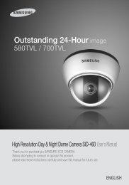
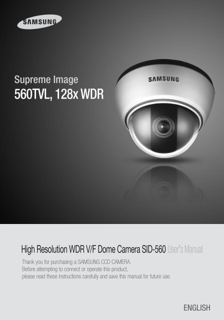
Before operating the camera, confirm the camera model and proper input powervoltage. In order to that you can understand this manual thoroughly, we'll introduce ourmodel description.n SID-560 SERIES• NTSC MODELSID-560(W)N• PAL MODELSID-560(W)Pn MODEL DESCRIPTION• SID-560(W)X _ _SIGNAL SYSTEMCAMERA COLOR• SIGNAL SYSTEMN → NTSC MODELP → PAL MODEL• CAMERA COLOR→ SILVER COLORW → IVORY COLORThe lightning flash with an arrowhead symbol, within an equilateral triangle isintended to alert the user to the presence of uninsulated “dangerous voltage”within the product's enclosure that may be of sufficient magnitude to constitutea risk of electric shock to persons.The exclamation point within an equilateral triangle is intended to alert the userto the presence of important operating and maintenance (servicing) instructionsin the literature accompanying the appliance.INFORMATION -This equipment has been tested and found to comply with limitsfor a Class A digital device, pursuant to part 15 of the FCC Rules. These limits aredesigned to provide reasonable protection against harmful interference when theequipment is operated in a commercial environment. This equipment generates,uses, and can radiate radio frequency energy and, if not installed and used inaccordance with the instruction manual, may cause harmful interference to radiocommunications.Operation of this equipment in a residential area is likely to cause harmfulinterference in which case the user will be required to correct the interference athis own expense.WARNING - Changes or modifications not expressly approved by the manufacturercould void the user’s authority to operate the equipment.WARNING - To prevent electric shock and risk of fire hazards:◆ Do NOT use power sources other than that specified.◆ Do NOT expose this appliance to rain or moisture.This installation should be made by a qualified service person andshould conform to all local codes.
OverviewInstallation❶ Pan Base : control panning angle of camera2 Rotate Base : control rotating angle of camera3 X3.6 Vari-focal Lens Module4 Rotate Base Holding Screw : fix rotated position5 Pan Base Holding Screws (Color : Silver) : fix panned position6 RS-485 Control Cable : The detailed description refers to p147 Power Input Jack 8 Video Output Jack9 Function Setup switch :Display the menu on the screen and move the cursor to four directions to confirmstatus or after changing a selected item.❿ Video Output Terminal to Monitor⓫ Shield Case ⓬ Dome CoverInstallationInstallation1) Separate the dome cover by counterclockwise rotation.2) Separate the shield case by pulling from the camerabody.[Figure-1]LatchLocking directionUnlocking direction(Counterclockwise)* To install the dome cover on the camera body, turn thelatches in locking direction as shown in the figure 1.Main Body(Camera)Shield CaseLocking direction(Clockwise)Dome coverNotes• The installation should be done by qualified service personnel or sysytem installers.• If the ceiling material is not strong enough to hold the installation screws, thecamera may fall off. Reinforce the ceiling as needed.When installing on a adapter plateAn arrow for installing directionsadapter plateM4 tappingscrew (provided)CAMERAUnlockingdirectionDome coverNotesLockingdirection1 Place the bracket provided on the installationsurface and fix it with the M4 tapping screws(provided).(Select either 85X85 or 83.5X46)2 When placing the camera body on the plate,insert the plate pin into the mounting hole onthe body as shown in figure-1 and fix it byturning clockwise.3 When placing the camera body on the plate,make sure the power and the BNC cablespass through their respective designatedholes.(When placing the cable through itsside, thread it through the hole at thebottom.)4 After installation and adjustment of thecamera are complete, secure the dome coverby turning it clockwise.Unlocking direction[Figure-1]Plate pinLockingdirection• Please locate an arrow on bracket for installing direction that you wish to observeArea and then fix it with the M4 tapping screws.COLOR DOME CAMERA10 User’s ManualCOLOR DOME CAMERA 11 User’s Manual
InstallationConnectionAdjust the panning and tilting, rotating while watching the monitorConnecting to MonitorConnect the VIDEO-OUT jack to the VIDEO-IN jack of monitor.145˚195˚73˚170˚Tilt BaseRotate Base<strong>CCTV</strong> CameraMonitorPan Base-170˚1) You can adjust camera to any direction by using Pan, Tilt, Rotate mechanism.• Pan Base moves by 170˚ to each side direction and 340˚ on the whole.• Tilt Base covers total 146˚ angle(73˚ to each side).• Angle range of Rotate Base is the same as that of Pan Base. But One side range is 195˚and another is 145˚2) Methods of adjustment• The case of wall installation1 After mounting the camera on a wall, adjusting the panning angle so that the camera canface the direction to monitor when tilting.2 And then adjust the tilting angle by rotating the tilt base.3 Loosen the rotate base hold screw and adjust rotate base for the best monitoring.4 Tighten the rotate base hold screw.• The case of ceiling installation1 After mounting the camera on a ceiling, adjusting the panning angle for better monitoringarea by rotating the pan base.2 And then adjust the tilting angle by rotating the tilt base.3 Loosen the rotate base hold screw and adjust rotate base for the best monitoring.4 Tighten the rotate base hold screw.• As the connecting method varies with the instruments, refer to the manual supplied with theinstrument.• If necessary, you can connect the monitor to the REMOTE jack on the back of your camera.• Only connect the cable when the power is turned off.• Set the 75Ω / Hi-Z selection switch as shown below if you have an intermediate device.Connecting to Power<strong>CCTV</strong> CameraIntermediate End monitorConnect the adaptor to the power input connector as shown in the figure below. Therecommended adaptor specification for SID-560N/SID-560P is DC 12V / 500mA.COLOR DOME CAMERA12 User’s ManualCOLOR DOME CAMERA 13 User’s Manual
ConnectionWhen the resistance value of copper wire is at [20˚C(68˚F)]Copper wire size (AWG) #24(0.22mm 2 ) #22(0.33mm 2 ) #20(0.52mm 2 ) #18(0.83mm 2 )Resistance (Ω/m) 0.078 0.050 0.030 0.018Voltage Drop (V/m) 0.028 0.018 0.011 0.006• As shown in the table above, voltage decreases as the wire gets longer. Therefore use ofan excessively long adaptor output line for connection to the camera may affect theperformance of the camera.*Standard voltage for camera operation : DC 12V ± 10%*There may be some deviation in voltage drop depending on the type of wire and the manufacturer.Notes• Be sure to connect power only after all the installation is complete.• Note that DC adaptor is not supplied with camera.• Ground should be connected to the GND terminal.RS-485 communication controlConnecting to RS-485 Control CableCONTROL CABLERED (TRX+)WHITE(TRX-)SPECRS-485+RS-485-Using a RS-485 communication, it will be able to control the OSD menu at the SAMSUNGTECHWIN System Controller or DVR.(1) The case which it controls from the PCUsing a RS-485 converter, It connects to RS-485 control cable outside camera and serialcableEX) SERIAL PORT OF THE PC(COM1) → SERIAL CABLE → RS-485 CONVERTER → RS-485 CONTROL CABLE(2) The case which it controls from the DVR or System ControllerIt connects the RS-485 control cable in the connection terminal of 485 control boards whichare connected with the DVR or System Controller.485 Control Board Connection Port RS-485 Control Port(+) CONNECTION TERMINAL RED (TRX+)(- ) CONNECTION TERMINAL WHITE (TRX-)* RS-485 Communication establishment initial valueItem Camera ID BAUD RATE UART MODE PET PKTInitial value 1 9600 8-NONE-1 ENABLEMenu ConfigurationLENSEXPOSUREWHITE BALANCEBACKLIGHT●DCSetup Menu●SHUTTER ●AGC ●SENS-UP●RETURN●ATW ●MANUAL ●AWC→SET●OUTDOOR ●INDOOR●OFF ●<strong>WDR</strong> ●BLC●HLCSSNR ●ON ●OFFDAY/NIGHT ●COLOR ●B/W ●AUTOIMAGE ADJUSTMENT(IMAGE ADJ.)SPECIALEXITNotes• When you construct external control systems for a camera control, please use to the SAMSUNGTECHWIN PROTOCOL or PELCO-D PROTOCOL.• When you connecting to RS-485 control cable, please peel off the outer skin inside the RS-485control cable.• In case of SCC-101 connection, change communication mode to 『8-E-1』 at 『Communicationconfiguration』menu. (For more information, refer to SCC-101 manual.)Operating Your Camera●V-REV ●H-REV ●D-ZOOM●SHARPNESS ●RETURN●CAMTITLE ●MOTION DET ●PRIVACY●DIS ●COMM ADJ ●LANGUAGE●RESET●RETURNCOLOR DOME CAMERA14 User’s ManualCOLOR DOME CAMERA 15 User’s Manual
Operating Your CameraMenu SetupUse the Function Setup switch on the main body of the camera.Function Setup switchLENSUsing this function, you can control screen brightness.1. When the SETUP menu screen is displayed, select ’LENS‘ by using the Function Setupswitch so that the arrow indicates ’LENS‘ .MAIN SETUP1.LENS DC2.EXPOSURE1. Press the Function Setup switch.• Main setup menu is displayed on the monitor screen.Select the function bymoving up or down directionof function setup switch.MAIN SETUP1.LENS DC2.EXPOSURE3.WHITE BAL ATW4.BACKLIGHT OFF5.SSNRON6.DAY/NIGHT AUTO7.IMAGE ADJ8.SPECIAL9.EXITChange the status bymoving right or left directionof function setup switch.DC : Select Auto Iris Lens• When DC is selected, you can control screenbrightness. The range of brightness control isbetween 1 and 70. Adjust the brightnessappropriately for optimal screen brightness.EXPOSUREMAIN SETUP1.LENS DC2.EXPOSURE3.WHITE BAL ATW2. Select a desired function using the Function Setup switch.• Place the cursor over a desired item.3. Set up a selected item by using the Function Setup switch.4. To finish the setting, select ‘EXIT’ and press the Function Setup switch.Notes• An item with the icon also has sub menus. To select a sub menu, select an item with the iconand press the Function Setup switch.• An item with the - - - icon is unavailable due to function settings.1. When the SETUP menu screen is displayed, select’EXPOSURE‘ by using the Function Setup switch so thatthe arrow indicates ’EXPOSURE‘.2. Select a desired mode using the Function Setup switch.SHUTTER : Because of using built--in dc lens, shutter speed is fixed at 1/60(PAL :1/50) basically.- A.FLK : Select this when you experience picture flicker, which can happen whenthere is a clash with the frequency of the installed lighting.COLOR DOME CAMERA16 User’s ManualCOLOR DOME CAMERA 17 User’s Manual
Operating Your CameraNotes• To produce better results with A.FLK, do not use it in conjunction with the <strong>WDR</strong>mode of the BACKLIGHT menu.AGC (AUTO GAIN CONTROL) :The higher the gain level, the brighter the screen - but the higher the noise.- OFF : Deactivates the AGC function.- LOW : Allows automatic gain control from 5.3dB to 30dB.- HIGH : Allows automatic gain control from 5.3dB to 42dB.SENS-UP :When it is night or dark, the camera automatically detects the light level andmaintains a clear picture if this mode is activated.- OFF : Deactivates the SENS-UP function.- AUTO : Activates the SENS-UP function.RETURN :Select this to save the changes in the EXPOSURE menu and return to the SETUP menu.Notes• If you press the Function Setup switch in ‘AUTO’ mode, You can adjust brightness byincreasing or decreasing the shutter speed. (x2 ~ x256)• Note that the higher the zoom level, the brighter the screen, but the more likely it isthat an after-image will appear.• Although Noise, Spots, and Whitish symptoms may occur in SENS-UP operationwhen the zoom level is increased, this is normal.White Balance (White Bal.)Use the White Balance function to adjust the screen color.1. When the SETUP menu screen is displayed, select ’White Bal.‘ by using the FunctionSetup switch so that the arrow indicates ’White Bal.‘ .2. Select a desired mode using the Function Setup switch.※ Select one of the following 5 modes, as appropriate for your purpose.ATW : Select this when the color temperature is between 1,800ºK and 10,500ºK.INDOOR : Select this when the color temperature is between 4,500ºK and 8,500ºK.OUTDOOR : Select this when the color temperature is between 1,800ºK and10,500ºK. (sodium light inclusion)AWC →SET : To find the optimal setting for the current luminance environment in this mode,set the point the camera towards a sheet of white paper and press theFunction Setup switch. If the environment changes, readjust it.MANUAL : Select this to fine-tune White Balancemanually. Set White Balance first by using theATW or AWC mode. After that switch toMANUAL mode, fine-tune the White Balanceand then press the Function Setup switch.NotesMAIN SETUP1.LENS DC2.EXPOSURE3.WHITE BAL ATW4.BACKLIGHT OFF• White Balance may not work properly under the following conditions. In this case select the AWCmode.1 When the color temperature of environment surrounding the subject is out of the control range(e.g. clear sky, or sunset)2 When the ambient illumination of the subject is dim.3 If the camera is directed towards a fluorescent light or is installed in a place where illuminationchanges dramatically, the White Balance operation may become unstable.COLOR DOME CAMERA18 User’s ManualCOLOR DOME CAMERA 19 User’s Manual
Operating Your CameraOperating Your CameraBACKLIGHTThis camera is designed so that it delivers a distinctive subject and background at thesame time, even when the subject is in backlight, unlike conventional cameras, byadopting a proprietary SV-IV DSP chip.1. When the SETUP menu screen is displayed,select ‘BACKLIGHT’ by using the FunctionSetup switch so that the arrow indicates‘BACKLIGHT‘.2. Select a desired mode using the FunctionSetup switch depending on the camerapurpose.BLC : Enables a user to directly select a desired area from apicture, and to view the area more clearly.• Select ‘BLC’ to adjust the area to be enhanced andenhancement level.<strong>WDR</strong> : When there are both bright and dark areas at thesame time, this mode makes both areas distinctive.MAIN SETUP1.LENS DC2.EXPOSURE3.WHITE BAL ATW4.BACKLIGHT OFF5.SSNR ONHLC(High Light Compensation) : lf there is a high light installed in a limitedenvironment such as an apartment parking garage or gas station entrance, removingthe high light makes it possible to view car license plates efficiently.- DAY : in normal daylight conditions, the HLC is not activated.- NIGHT : lf a high light that is larger than a certain size is present on the screen,remove the high light to see license plates clearly.- HLC : Enable a user to select a mask color of high light area from a picture.OFF : Not being used.3. Select a desired mode using the Function Setup switch and press the Function Setupswitch.<strong>WDR</strong>OFF• Select ‘<strong>WDR</strong>’ to adjust the <strong>WDR</strong> LIMIT and LEVEL.- LIMIT : Adjust the <strong>WDR</strong> sensitivity by selecting LOW,MIDDLE, or HIGH.- LEVEL : Adjust the <strong>WDR</strong> brightness by controlling thebar from 0 to 100.• The <strong>WDR</strong> compensates for backlight more effectively than previous models, byapplying an optimum fusion ratio when combining the high speed shutter used inbright areas and the low speed shutter used in dark areas.Notes• Since the following symptoms may occur according to the ambient illumination when<strong>WDR</strong> is selected, set it to OFF.❶ Color or screen changes unnaturally.2 Noise appears in the bright part of the screen.• Since the performance of the <strong>WDR</strong> function may be affected by the area of the bright partof the screen, optimize the installation angle for the best <strong>WDR</strong> performance.• If you increase LIMIT, the screen display may be distorted.• In a dark environment, the HLC is only activated when a high light that is larger than acertain area is present.• The HLC is not activated in light or overly dark conditions.COLOR DOME CAMERA20 User’s ManualCOLOR DOME CAMERA 21 User’s Manual
Operating Your CameraSSNRThis function reduces the background noise in a low luminance environment.1. When the SETUP menu screen is displayed, select ’SSNR‘ by using the FunctionSetup switch so that the arrow indicates ’SSNR‘.2. Select a desired mode using the Function Setup switch.OFF : Deactivates SSNR. Noise is not reduced.ON : Activates SSNR so that noise is reduced.3. Set the SSNR mode to ’ON‘ and press the FunctionSetup switch. Then you can adjust the noisereduction level.Notes• You cannot set the SSNR to ‘ON’ or ‘OFF’ when the AGC mode of the EXPOSUREmenu is ‘OFF’.• When adjusting the noise reduction level of the SSNR mode, remember that thehigher the level set, the more the noise level will be reduced but that after imagemay also occur.DAY/NIGHTMAIN SETUP1.LENS DC2.EXPOSURE3.WHITE BAL ATW4.BACKLIGHT OFF5.SSNRON6.DAY/NIGHT AUTOYou can display pictures in color or black and white.1. When the SETUP menu screen is displayed, select ‘DAY/NIGHT’ by using theFunction Setup switch so that the arrow indicates ’DAY/NIGHT‘.2. Select a desired mode using the Function Setup switch according to the picture displayyou want.COLOR : The picture is always displayed in color.B/W : The picture is always displayed in black and white.To turn on or off the burst signal on B/W mode,please press the Function Setup switch.AUTO : The mode is switched to ‘Color’ in a normalenvironment, but switches to ‘B/W’ mode whenambient illumination is low. To set up thesswitching time or speed for AUTO mode, pressthe Function Setup switch.- DWELL TIME : You can select the duration time aboutchanging the day/night mode.→ 5s, 7s, 10s, 15s, 20s, 30s, 40s, 60s- DURATION : You can select brightness of illuminationabout changing theday/night mode.Color → B/W B/W → ColorFast 2.5 lux 4 luxSlow 0.8 lux 6 lux* The brightness of illumination is changeable byinstalled environment.EXTERN : This mode allows you to apply a desired filter to external signals.NotesMAIN SETUP1.LENS DC2.EXPOSURE3.WHITE BAL ATW4.BACKLIGHT OFF5.SSNRON6.DAY/NIGHT AUTO7.IMAGE ADJ• You cannot control the DAY/NIGHT menu when AGC in the EXPOSURE menu is ‘OFF’.At this time, the exchange between DAY mode and NIGHT mode operates as like selecting ‘COLOR’mode.• The OSD key does not work for 3 seconds when switching to Color or B/W, to ensure stablecamera operation.• The camera may focus less well under infrared illumination than under normal illumination.COLOR DOME CAMERA22 User’s ManualCOLOR DOME CAMERA 23 User’s Manual