562 TRANSACTIONS OP THE A.S.M.E. OCTOBER, 1941F i q . 3 S c h e m a t ic A r r a n g e m e n to f E x p e r im e n t a l A p p a r a t u sF i g . 4 A ssem b l y o f E x p e r im e n t a l A p p a r a t u s a t G as-I n l e t E ndF iq . 5 A s s e m b ly o f E x p e r i.m e n t a l A p p a r a tc b a t G a s -O u t l e t E n d
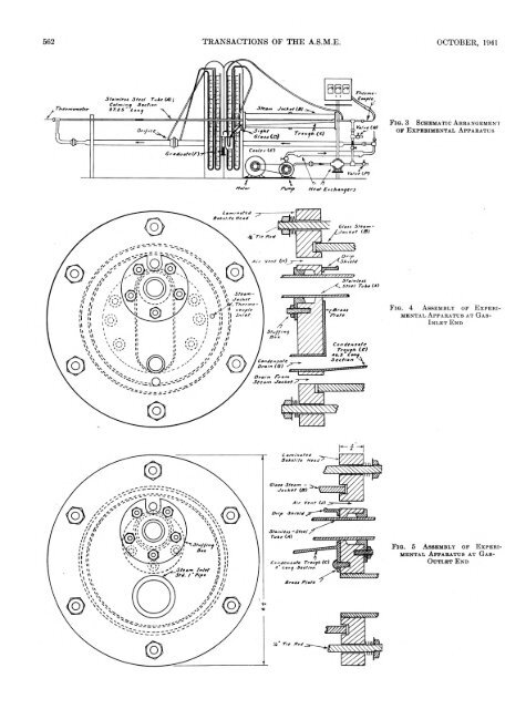
COLBURN, COGHLAN—HEAT TRANSFER TO HYDROGEN-NITROGEN MIXTURES INSIDE TUBES 563F i g . 6 L o n g i t u d i n a l - S e c t i o nV i e w o f O u t l e t F r o m T e s t S e c t i o n , S h o w i n g S c h e m a t i c A ss e m b l y o f T h e r m o c o u p l e U s e dt o M e a s u r e O u t l e t T e m p e r a t u r eboth gases and liquids, include the Prandtl number. For gasmixtures, however, one might question whether the proper valueto use is the Prandtl number of the mixture or some combinationof the Prandtl numbers of the pure components.If the Prandtl number of the gas mixture is the proper value touse in heat-transfer formulas, then data covering a range ofvalues of this number from 0.73 to 0.45 might make possible aselection of the best type of formula. Chilton (2) has shown aconvenient comparison of the exponential-type relation with thetheoretical relations of Prandtl (3) and of von Kdrmdn (4).These relations are different in the range of Prandtl numberscovered by these mixtures, and so the results should prove ofgreat interest in testing these equations.D e t a il s o f A p p a r a t u s U s e dThe apparatus chosen for this investigation was of the gas-intubestype, inasmuch as it was felt that the most reliable resultscould be obtained in such an apparatus. A stainless-steel tubewas used so that there would be no corrosion and change of surfaceconditions, and also because the low thermal conductivityof stainless steel would minimize heat conduction through theends of the appaj-atus. At the same time the thermal conductivityis sufficiently great to make the thermal resistance of the tubenegligible for the transfer of heat to the gas. The tube was steamjacketed,the outer cylinder being glass so that the type of condensationon the tube could be observed. The condensate fromthe tube was collected in a trough located inside the steam spaceand led outside the apparatus. The condensate on the glassjacket, resulting from radiation losses, was drained separatelyand discarded. This arrangement was made in the attem pt toobtain good heat balances. Atmospheric steam was supplied tothe jacket, and some steam was continuously vented at both endsof the jacket to insure that no air would collect. The steam-inletpipe to the jacket is 1 in. diam and is located below the trough.These conditions permit a very low steam velocity into the exchangerand at an elevation such that any moisture in the steamwould not be carried into the trough in which the condensatefrom the tube collects.TA B LE 1 D IM E N S IO N S OF T E S T SE C T IO NStainless-steel tubeInchesInside diam eter................................................................................ 0.50Outside diam eter............................................................................. 0.63Total length....................................................................................... 142.75H eated length ................................................................................... 48.75Length of calming section............................................................ 87.25Unheated length a t outlet end.................................................... 6.75Distance between pressure ta p s ................................................. 52.50The arrangement of the apparatus is shown in Fig. 3. A smallblower was used to recirculate the gas, and coolers were insertedbefore and after the blower to bring the gas to room temperatureat the entrance of the test apparatus. The rate of flow of the gaswas measured by an orifice meter constructed with throat taps,according to the specifications of the Fluid Meters Report.The metering tube was 2 in. diam, and orifices used were of 0.375,and 0.255 in. diam. These were calibrated on air, using a calibratedgas-meter prover, and the coefficient was found to be 0.61.Dimensions of the test section are given in Table 1.The glass steam jacket was supported by Iaminated-bakeliteflanges, shown in Figs. 4 and 5, at the ends of the heated section,drawn together by tie rods outside the glass jacket. Theseflanges were made tight to the stainless-steel tube by packingglands. Owing to the low thermal conductivity of these flanges,very little heat could be conducted to the tube beyond the insidesurfaces of the flanges.The heat, given up by the steam in heating the gas, was determinedby measuring the condensate collecting in the trough anddraining through the sight glass at constant level. This amountwas corrected for the small amount of liquid collecting on theflanges above the trough, and for the small heat loss from thesight glass; this correction was determined by blank runs when nogas was flowing, and was found to be 0.0258 lb per hr.T e m p e r a t u r e D e t e r m in a t io nThe temperatures were determined as follows: The inlet-gastemperature was measured by a calibrated thermometer at theentrance to the calming section. This temperature was adjustedby the coolers to be identical with the room temperature adjacentto the calming section, so that no increase or decrease in the temperatureof the gas would take place before it reached the heatedportion of the tube. The outlet temperature was measured witha special thermocouple, shown in Fig. 6, which was constructedto minimize radiation errors and to insure good mixing of the gasbefore the thermocouple. I t was made so that it could be slidout of the way when pressure drops were measured. The aluminumtube K acted as a radiation shield. The mixing device Lconsisted of two “doughnuts” and one disk of copper held inplace by being soldered to copper wires. This mixer was thenpainted with a thermosetting bakelite varnish and cured, in orderto minimize heat conduction from the tube. Laminated-bakelitespacers M kept the thermocouple centered. The steam temperaturewas also measured with a thermocouple in the jacket, andchecked against barometric pressure.Commercial hydrogen and nitrogen were used, and the compositionof the mixture was determined immediately following aseries of runs by means of a Bureau of Mines apparatus. Althougha special packing gland was built onto the blower, therewas a slight leak at that point, and a small amount of air wouldleak into the apparatus. This was determined by analyzing themixture for oxygen. This amount, less than 1 per cent, was calculatedas nitrogen. The gas pressure in the system was essentiallyatmospheric. Actually, enough gas to cause a slight pressurewas supplied to the system at the beginning of a run. Thispressure soon dropped until atmospheric pressure prevailed at thestuffing box of the blower.R e s u l t s o f E x p e r im e n t sThe principal results of this investigation are given in Table 2and in Figs. 7 to 12. The reliability of the data is measured bythe heat balances, the deviations from which are given by the
- Page 1 and 2: Transactionsof theHeat Transfer to
- Page 3: H eat T ran sfer to H ydrogen-N itr
- Page 7 and 8: COLBURN, COGHLAN—HEAT TRANSFER TO
- Page 9 and 10: Electric-Slip Couplings for UseW it
- Page 11 and 12: ANDRIOLA—ELECTRIC-SLIP COUPLINGS
- Page 13 and 14: ANDRIOLA—ELECTRIC-SLIP COUPLINGS
- Page 15 and 16: ANDRIOLA—ELECTRIC-SLIP COUPLINGS
- Page 17 and 18: ANDRIOLA—ELECTRIC-SLIP COUPLINGS
- Page 19 and 20: Flexible Couplings for Internal-C o
- Page 21 and 22: ORMONDROYD—FLEXIBLE COUPLINGS FOR
- Page 23 and 24: ORMONDROYD—FLEXIBLE COUPLINGS FOR
- Page 25 and 26: C om bustion Explosions in P ressur
- Page 27 and 28: CREECH—COMBUSTION EXPLOSIONS IN P
- Page 29 and 30: CREECH—COMBUSTION EXPLOSIONS IN P
- Page 31 and 32: M athem atics of Surge Vessels and
- Page 33 and 34: MASON, PHILBRICK—MATHEMATICS OF S
- Page 35 and 36: MASON, PHILBRICK—MATHEMATICS OF S
- Page 37 and 38: MASON, PHILBRICK—MATHEMATICS OF S
- Page 39 and 40: MASON, PHILBRICK—MATHEMATICS OF S
- Page 41 and 42: MASON, PHILBRICK—MATHEMATICS OF S
- Page 43 and 44: MASON, PHILBRICK—MATHEMATICS OF S
- Page 45 and 46: 604 TRANSACTIONS OF THE A.S.M.E. OC
- Page 47 and 48: 606 TRANSACTIONS OF THE A.S.M.E. OC
- Page 49 and 50: 608 TRANSACTIONS OF THE A.S.M.E. OC
- Page 51 and 52: 610 TRANSACTIONS OF THE A.S.M.E. OC
- Page 53 and 54: TRANSACTIONS OF THE A.S.M.E. OCTOBE
- Page 55 and 56:
614 TRANSACTIONS OF THE A.S.M.E. OC
- Page 58 and 59:
618 TRANSACTIONS OF THE A.S.M.E. OC
- Page 60 and 61:
620 TRANSACTIONS OF THE A.S.M.E. OC
- Page 62 and 63:
622 TRANSACTIONS OF THE A.S.M.E. OC
- Page 64 and 65:
624 TRANSACTIONS OF THE A.S.M.E. OC
- Page 66 and 67:
626 TRANSACTIONS OF TH E A.S.M.E. O
- Page 68 and 69:
628 TRANSACTIONS OF THE A.S.M.E. OC
- Page 70 and 71:
Flow P roperties of L ubricantsU nd
- Page 72 and 73:
NORTON, KNOTT, MUENGER—FLOW PROPE
- Page 74 and 75:
NORTON, KNOTT, MUENGER—FLOW PROPE
- Page 76 and 77:
NORTON, KNOTT, MUENGER—FLOW PROPE
- Page 78 and 79:
NORTON, KNOTT, MUENGER—FLOW PROPE
- Page 80 and 81:
NORTON, KNOTT, MUENGER—FLOW PROPE
- Page 82 and 83:
NORTON, KNOTT, MUENGER—FLOW PROPE
- Page 84 and 85:
646 TRANSACTIONS OF THE A.S.M.E. OC
- Page 86 and 87:
648 TRANSACTIONS OF THE A.S.M.E. OC
- Page 88 and 89:
650 TRANSACTIONS OF THE A.S.M.E. OC
- Page 90 and 91:
652 TRANSACTIONS OF THE A.S.M.E. OC
- Page 92 and 93:
A H igh-T em perature Bolting M ate
- Page 94 and 95:
WHEELER—A HIGH-TEMPERATURE BOLTIN
- Page 96 and 97:
WHEELER—A HIGH-TEM PERATURE BOLTI
- Page 98 and 99:
WHEELER—A HIGH-TEM PERATURE BOLTI
- Page 100 and 101:
WHEELER—A HIGH-TEMPERATURE BOLTIN
- Page 102 and 103:
WHEELER—A HIGH-TEMPERATURE BOLTIN
- Page 104 and 105:
W HEELER—A HIGH-TEMPERATURE BOLTI