
You also want an ePaper? Increase the reach of your titles
YUMPU automatically turns print PDFs into web optimized ePapers that Google loves.
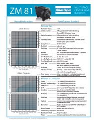
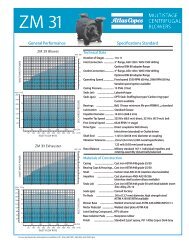
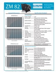
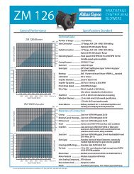
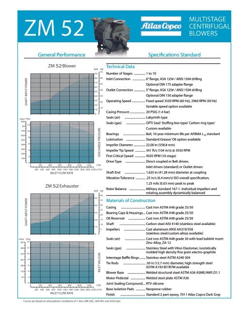
<strong>ZM</strong> 52MULTISTAGECENTRIFUGALBLOWERSGeneral PerformanceSpecifications StandardSHAFT INPUT POWERmbar PSIG9001280700 106008500400 63004200210000mbar inHg467 1440033326720013367SHAFT INPUT POWER1210864200<strong>ZM</strong> 52 Blower<strong>ZM</strong> 52 ExhausterBHP kW907080 60705060504040 3030202010100DISCHARGE PRESSURE200 400 600 800 1000 1200 CFM200 400 600 800 1000 1200 1400 1600 1800 2000 2200 m 3 /hrINLET FLOW RATEBHP kW40503540 3025302020 15101050INLET VACUUM200 400 600 800 1000 1200 CFM200 400 600 800 1000 1200 1400 1600 1800 2000 2200 m 3 /hrINLET FLOW RATETechnical DataNumber of Stages ............... 1 to 10Inlet Connection .................. 6” flange, ASA 125# / ANSI 150# drillingOptional DIN 175 adapter flangeOutlet Connection ................ 5” flange, ASA 125# / ANSI 150# drillingOptional DIN 150 adapter flangeOperating Speed .................. Fixed speed 3550 RPM (60 Hz), 2960 RPM (50 Hz)Variable speed option availableCasing Pressure ..................... 20 PSIG (1.4 bar)Seals (air) ............................ Labyrinth typeSeals (gas) .......................... OPTi Seal/ Stuffing box type/ Carbon ring type/Custom availableBearings .............................. Ball, 10-year minimum life per AFBMA L 10 standardLubrication .......................... Standard Grease/ Oil option availableImpeller Diameter ................ 22.00 in (558.8 mm)Impeller Tip Speed .............. 341 ft/s (104 m/s) @ 3550 RPMFirst Critical Speed .............. 4505 RPM (10-stage)Drive Type ........................... Direct coupled or Belt driven,Inlet driven (standard) or Outlet drivenShaft End ............................ 1.625 in (41.28 mm) diameter at couplingVibration Tolerance ............. .25 in/s (6.4 mm/s) ISO overall specification,1.25 mils (0.03 mm) peak to peakRotor Balance ...................... Military standard 167-1. Individual impellers androtating assembly dynamically balancedMaterials of ConstructionCasing ................................. Cast iron ASTM A48 grade 25/30Bearing Caps & Housings ... Cast iron ASTM A48 grade 25/30Oil Reservoir ....................... Cast iron ASTM A48 grade 25/30Shaft ................................... Carbon steel AISI 4140 (stainless steel available)Impellers ............................. Cast aluminum ANSI AA319/356(stainless steel/custom alloys available)Seals (air) ............................ Cast iron ASTM A48 grade 30 with lead babbitt insertZinc-Alloy, ZA-12Seals (gas) .......................... Stainless Steel with Viton Elastomer, isostaticallymolded high density fine grain electro-graphiteInterstage Baffle Rings ........ Stainless steel ASTM A240 304Tie Rods .............................. .50 in (12.7 mm) diameter, high strength steelASTM A193-B7/B7M availableBlower Base ........................ Welded structural steel ASTM A36 ASME/AWS D1.1Motor Pedestal .................... Welded steel plate ASTM A36Joint Sealing Compound .... RTV siliconeBase Isolation Pads ............. Neoprene rubberFinish .................................. Standard 2 part epoxy, 7011 <strong>Atlas</strong> <strong>Copco</strong> Dark GrayCurves are based on atmospheric conditions of 1 Atm, 68F/20C, 36% RH, and 3550 rpm
<strong>ZM</strong> 52 MULTISTAGE CENTRIFUGAL BLOWERInlet and Outlet Orientation OptionsThe orientation of the inlet and outlet is selectable from any of threedifferent positions, as viewed when facing the exterior of the part:POSITION2POSITION1*INLETPOSITIONS*Standard configuration.POSITION3POSITION2OUTLETPOSITIONSPOSITION1*POSITION3Weight and InertiaWeight* Wk 2Model lb kg lb-ft 2 kg-m 25201 530 240 6 0.275202 657 298 12 0.535203 780 354 19 0.785204 910 413 25 1.045205 1137 516 31 1.305206 1163 528 37 1.565207 1290 585 43 1.825208 1417 643 49 2.085209 1543 700 55 2.345210 1670 757 61 2.60*Approximate weight for blower only.† Inertia based on cast impellers.General ArrangementØ .94 (23.8)(4) HOLESØ6.00 (152.4)Ø11.00 (279.4)3/4-10 UNC TAP(8) HOLESØ5.00 (127.0)Ø8.50 (215.9) B.C.Ø10.00 (254.0)30.91(785.2)11.50(292.1)14.75(374.6)28.82(732.0)19.00(482.6)35.45(900.4)2.75 (69.8)Ø9.50 (241.3) B.C.3/4-10 UNCTAPISOLATION PADSF10.25(260.4)6" INLET 5" OUTLETLBA7.26(184.4)6.64(168.7)14.50(368.3)6.20(152.4)1.50(38.1)24.50(622.3)21.00(533.4)Dimensions*Model A B F † L †5201 4.63 (117) 8.50 (216) 47 (1194) 50 (1270)5202 7.88 (200) 11.75 (298) 56 (1422) 59 (1499)5203 11.13 (283) 15.00 (381) 56 (1422) 59 (1499)5204 14.38 (365) 18.25 (464) 66 (1676) 69 (1753)5205 17.63 (448) 21.50 (546) 66 (1676) 69 (1753)5206 20.88 (530) 24.75 (629) 77.5 (1969) 80.5 (2045)5207 24.13 (613) 28.00 (711) 77.5 (1969) 80.5 (2045)5208 27.38 (695) 31.25 (794) 77.5 (1969) 80.5 (2045)5209 30.63 (778) 34.50 (876) 88 (2235) 91 (2311)5210 33.88 (860) 37.75 (959) 88 (2235) 91 (2311)*Dimensions in inches and (millimeters) and are approximate. Do not usefor construction purposes.† Dimension may vary depending on motor frame size.8www.atlascopco.uswww.efficiencyblowers.comE-TS-<strong>ZM</strong>052-001, REV 00 11/28/2012