LE-8200 - TR instruments
LE-8200 - TR instruments
LE-8200 - TR instruments

Create successful ePaper yourself
Turn your PDF publications into a flip-book with our unique Google optimized e-Paper software.
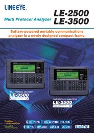
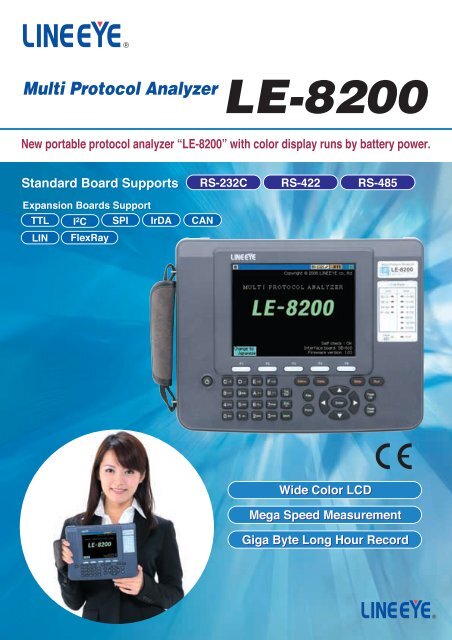
Multi Protocol Analyzer<strong>LE</strong>-<strong>8200</strong>New portable protocol analyzer Ò<strong>LE</strong>-<strong>8200</strong>Ó with color display runs by battery power.Standard Board SupportsExpansion Boards SupportTTLLINI 2 CFlexRaySPIIrDARS-232C RS-422 RS-485CANWide Color LCDMega Speed MeasurementGiga Byte Long Hour Record
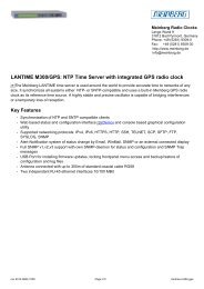
Multi Protocol AnalyzerBattery-powered PortableCommunications Analyzer<strong>LE</strong>-<strong>8200</strong>RoHS DirectiveCompatibleA product incorporatingfeatures for the protectionof the global environment,such as the elimination oftoxic substances, and apower-saving design.The <strong>LE</strong>-<strong>8200</strong> is the top-level model of battery-powered portable communications analyzers.The <strong>LE</strong>-<strong>8200</strong> has an enlarged display in response to an increasing demand without degrading the excellent portability of the <strong>LE</strong> Series.The <strong>LE</strong>-<strong>8200</strong> is ideal for development tests of communications systems, industrial equipment, a variety of in-vehicle networks,and after-sale services for products along with trouble analysis.A battery-powered model in B5 size, weighing 1.1 kg, and operating continuously for 4 hours.RS-422/RS-485 (RS-530) measurement portUsed for X.21, RS-449, and V.35 communications over dedicated cable (*1)with no extra attachments required.DC input connectorUsed to connect the AC adapter (provided) thatcovers a global range of power supply voltage.External signal terminalUsed for external signal voltage measurement input and external trigger I/O signals.RS-232C (V.24) measurement portUsed to connect the dedicated cable (*1) with DSUB 9 pins for measurement.Exchangeable measurement board5.7-inch TFT color displayProvided with a power-savingwhite <strong>LE</strong>D backlight.Hand strapPower supplyON/OFF switchAuto power-off is possible.Function keysUsed to make displayed code changes or screen mode changes.Special data items are expressed in individual signs.Menu keyUsed to beginoperations.Line State <strong>LE</strong>DContinuously displays the state ofcommunications line with a 2-color <strong>LE</strong>D.(Example of display signs)Start flagEnd flagShort frameBlock check OKBlock check NGParity errorFraming errorPE and FE simultaneous errorBreakIdle time (frame interval time)Time stamp (frame arrival time)Measurement start keyAutomatic repetitive measurement ispossible at specified times.In RS-232Ccommunications*1: An optional dedicated cable is required.Red: ON space stateGreen: OFF mark stateOFF: Not in use or not wired*2: The optional <strong>LE</strong>-PC800G PC Link software is required.*3: The CF card slot guarantees the operation of onlyLINEEYE's optional CF card.2
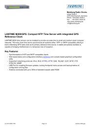
Powerfully backing up the measurement ofcommunications networks of ubiquitous society.5.7-inch Large-sized ColorTFT LCDThe large-sized LCD is an easy-to-understandcolor display showing a flow ofcommunications protocol and data transmittedor received, thus greatly improving theefficiency of measurement data analysis.Furthermore, the display of an English orJapanese guide accurately supports high-levelmeasurement over communications.[Example of Japanese display][Example of English display]Supports TTL, I 2 C, SPI, IrDA, CAN,LIN, and FlexRaySupports various types of communications protocolswidely used over RS-232C/422/485. Also supports newcommunications standards by exchanging themeasurement board.See pages 8 and 9 for details.Measurement Functions Developedin Response to CustomersÕ DemandsIncorporates improved measurement functions, such asthe comparison display of two divided areas, precise timestamp recording in 1-µs units, and improved triggeringwith the simultaneous detection of eight conditions.See pages 4 and 5 for details.AUX connectorUsed for printing out andfirmware updating.USB2.0 connectorPC linking is possible athigh-speed transmission. (*2)Long Recording Time ofCommunications DataIncorporates a 100-MB capture memory that is ideal forthe analysis of high-speed, large-volume communications.The use of the CF card enables the continuous recordingof communications data for as long as several days.See page 4 for details.Supports Logic Analyzer Analysisand Analog Waveform AnalysisRealizes precise timing analysis and waveformobservation easily with no general-purpose measuring<strong>instruments</strong> used.See page 5 for details.CF card slotThe CF card with a maximumcapacity of 16 gigabytes issupported. (*3)Measurement at Low toMega SpeedsUsing high-precision DPLL technology for open baudrate support, transmission and reception speeds can beseparately set to 4 effective digits for measurement tests.See page 4 for details.Measurement Linked with PCThe PC link function (*) , which realizes PC-linkedmeasurement, enables high-speed USB connections, thusperforming the remote monitoring of measuring objects athigh speed. *: The optional <strong>LE</strong>-PC800G PC Link software is required.See page 9 for details.Incorporating remote monitor, simulation, and BERT functionsto improve the efficiency of the development testing andtrouble analysis of RS-232C/RS-422/RS-485 communications.Multi Protocol Analyzer<strong>LE</strong>-<strong>8200</strong>3
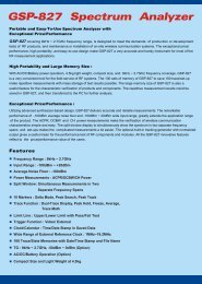
FunctionsThe monitor function exactly records and visualizes communications data.The line monitor function allows the recording of communications data and provides aneasy-to-understand large-sized display without affecting the communications lines.This function makes it possible to grasp the conditions of transmission and reception,thus greatly shortening the required time of troubleshooting. As a standard feature, the<strong>LE</strong>-<strong>8200</strong> supports a variety of communications standards, such as binary synchronouscommunications (BSC) for character-synchronous transmission, and high-level datalink control (HDLC) for bit-synchronous transmission as well as asynchronouscommunications that are widely used for PC peripheral and microcontrollerapplications. By adding an optional expansion kit, the <strong>LE</strong>-<strong>8200</strong> will support many morecommunications standards.BeforeconnectionAftermonitorcableconnection[Example of connection for online monitoring]Communications Monitor cableDTEnetworkSDDCERDSD RD[Example of display with line state] [Example of X.25 protocol translation] [Example of PPP translation]Display of Two Divided Areas for Ease of ComparisonNew FunctionFreely Set with Four Effective Digits for Transmission and ReceptionThe display of two divided areas isconvenient for the comparison ofnormal and abnormal communicationslog records. It is possible to scroll thetwo divided areas on the upper halfand lower half of the screen individuallyor simultaneously, which allows thecomparison of the two communicationsrecords efficiently.[Example of two divided areas]Using high-precision DPLLtechnology for open baud ratesupport, transmission and receptionspeeds can be separately set with 4effective digits to a baud rate rangebetween 50 bps and 4 Mbps. Therequired conditions of transmissionor reception data, such as the bitconfiguration, bit transfer sequence,polarity, and modulation format canbe freely selected to meet many testsituations.[Example of communications protocol settings]High-precision Time Stamp Recorded at 1-µs IntervalsNew FunctionLong Recording Time Allowing Rolling back to Points of Communications FailuresThe time stamp shows the transmission or reception time of the head data of eachcommunications frame. In addition to the conventional real-time time stamp, the <strong>LE</strong>-<strong>8200</strong>incorporates a high-precision time stamp that records the elapsed time of transmission orreception at minimal 1-µs intervals from the start of measurement. This function haswidened the range of applications from the narrowing down of data on a specified time-anddatebasis to the checking of delicate timing. Moreover, the <strong>LE</strong>-<strong>8200</strong> displays idle time, thusmaking it possible to check the response time and timeout of transmission or reception at aglance. In addition, it is possible to judge each frame in asynchronous communications byspecifying a non-communications period of 1 to 100 milliseconds or end data.[Example of time stamp]14 hrs 27 minutes on the 18th[Example of idle time]0.046 second24 minutes 53 seconds 180 millisecondsElapse of 5 seconds 398 milliseconds 614 microseconds2.78 seconds6 hours 36 minutes 12 secondsThe <strong>LE</strong>-<strong>8200</strong> has 100-MB capture memory that gains high-speed access to megaspeedcommunications, and is provided with ring and fixed buffer modes. The usercan select the ring buffer mode for endless recording or the fixed buffer mode to stoprecording automatically when the memory is full. Furthermore, the <strong>LE</strong>-<strong>8200</strong>incorporates an auto save function that makes it possible to save the monitoredcontent of captured memory on a high-capacity compact flash (CF) card in aspecified file size continuously. This is useful for identifying rare communicationsfailures of unknown causes.[Continuous recording time reference *1 ]Applicable transmission speed9600bps1MbpsMain memory onlyApproximately 6 hoursApproximately 220 seconds16-GB CF card *2Approximately 960 hoursApproximately 10 hours*1: In the case of full-duplex transmission of 1-kilobyte data at 1-millisecond intervals,both transmission and reception data will consume 4-byte memory for each capture.*2: With the optional CF-16GX used.Search FeatureThe <strong>LE</strong>-<strong>8200</strong> allows the scrolling or paging of measured data freely. This powerfulfeature makes it possible to search specific data items from a large volume ofmeasured data and transmission or reception frames along with time stamps within aspecified period, thus greatly increase the efficiency of offline analysis. The powerfulsearch feature allows you to locate specific data and perform counting.4
MULTI PROTOCOL ANALYZER<strong>LE</strong>-<strong>8200</strong>Supporting Logic Analyzer Analysis and Analog Waveform AnalysisNew FunctionThe logic analyzer, which digitally displays the waveformsof communications line timing, operates ata sampling rate up to as high as 40 MHz. Furthermore,this feature realizes the simultaneous displayof 12 lines by making use of the large-sized screen.Besides, the adoption of function keys ensures theoperation of the time cursor with ease. Furthermore,if the OP-SB85 optional expansion kit is used,measurement of analog voltage waveforms at amaximum rate of 40M samples per second will bepossible. Therefore, you will be able to realize detailedwaveform observation without carrying aheavy general-purpose measuring instrument whenyou are on a business trip. These functions help toidentify hardware problems. You can also use it foreducational purposes, comparing documents forcommunications protocol.[Example of Logic Analyzer Analysis][Example of Analog Waveform Analysis]Trigger Function with Detection Capability Reinforced TwiceFunctional EnhancementThe trigger function controls the operation of measurement when the function detects specificcommunications status. Conventional models have four combinations of trigger conditions and triggeractions. On the other hand, the <strong>LE</strong>-<strong>8200</strong> is provided with eight combinations for ease of makingsettings that are more flexible. This function not only enables the detection of eight types of conditionssimultaneously but also makes it possible to detect particular conditions in sequence. Complicatedcommunications events can be precisely grasped.Trigger 4[Contents of trigger settings]Trigger 0: External trigger output in case of errorgeneration.Trigger 1: Saves the data before and after idle time on theCF card when the idle time exceeds the setvalue.Trigger 2: Starts timer 0 when the specified signal line is 1.Trigger 3: Stops timer 0 when the specified signal line is 0.Trigger 4: Enables trigger 5 when start flags 01h, 02h, 03h,and F1h or 01h, 02h, 03h, and F3h are detectedin sequence in SD.Trigger 5: Stops measurement immediately when 58h, 59h,5Ah, arbitrary 2-byte data, and the end flag aredetected in sequence in RD.Trigger 6: Stops measurement when timer 0 coincides withthe set value.Trigger 5Voltage Measurement of Communications Line with EaseWith the feature of delay time measurement,a period of change of the communicationscontrol line from the present state to anothercan be measured at a 0.1-ms resolution.The feature is added with a function tomeasure the maximum, minimum, andpresent voltage amplitudes of SD, RD, D<strong>TR</strong>,and external EXT signals over RS-232C.This allows ease of the voltage amplitudemeasurement of wiring in connectors wherethe probes of testers cannot reach smoothly,thus contributing to the investigation ofcommunications trouble caused by aninsufficiency in the amplitudes of signalsresulting from a circuit voltage drop.New Function[Example of analog & delay time measurement]Graphic Display of Hourly Communications StatusThis statistical analysis feature is used tomeasure the volume of communications andthe number of occurrence times of specificcommunications status for a specified periodranging from 1 to 240 minutes with the resultsgraphically displayed. Condition 0 and condition1 of the trigger function can be specified astarget items. Therefore, it is possible to graspnot only the change of communications traffic(the rate of line usage) but also the number oftransmission and reception times of specificdata strings and the occurrence frequencytendency of errors on a time zone basis.Furthermore, the auto range display withincreased graphic resolution allows ease ofseeing slight changes.[Example of graphical display of statistical analysis]5
FunctionsSimulation function provides the actual operating environments.With the simulation feature, LINEEYE protocol analyzers act as the counterpart to the target device and performtransmission and reception tests according to protocol. Even in the early stages of development when matchingdevices are not available, it provides six types of simulation modes. Error handling process can be checked bysending data with parity errors. Margins can be evaluated by intentionally shifting communications speed. Forexample, test the 9600bps target device at 9840bps speed. In addition, data transmission can be linked with thechanges in the signal lines, and an automatic control of RS-485 transmission driver IC is supported.[Example of connection for simulation]Test dataMANUAL modeThe MANUAL mode allows you to send the dataregistered in transmission table which correspondsto the "0" to "F" keys. The data can be sent with onepress of a key. While checking replies from a unitunder development with the monitoring feature, youcan easily and simply test the communicationsprocess. You can also send fixed data by pressing akey combination of the SHIFT and "0" to "D" keys,as well as turn RTS/CTS and D<strong>TR</strong>/DCD signal lineson/off with the SHIFT and "E"/"F" key combinations.[Data table setup]PROGRAM modeBy creating a purpose-specific command program, the communications protocol can be flexibly simulatedalongside condition monitoring. The program is created using the menu selection, so it is easy to master.[PROGRAM mode setup]BUFFER mode[BUFFER mode setup]In the BUFFER mode, you can selectbetween transmission and reception, andsend transmitted or received data that hasbeen captured in the buffer using the unit'smonitoring capabilities, as simulation datawithout requiring further manipulation. Thismode is effective in conducting reproducibilitytests using the same data as that monitoredunder actual communications conditions.FLOW modeFlow control can be simulated on thetransmission and reception-lines using X-on/offflow control or the control line handshake. In thetransmission mode, up to 16 cycles of data fromtransmission start until a generated interruptrequest can be displayed. In the reception mode,you can set the number of received data cyclesuntil a transmission interrupt request isgenerated, as well as the time until thetransmission resume request is generated.ECHO modeIn the ECHO mode, LINEEYE protocolanalyzers internally return receiveddata. Buffer echo to send back databy a frame, character echo to sendback data by a character and loopback echo to return by the hardwarecan be selected. It is used to testdisplay terminals and communicationsterminals.POLLING modeThe POLLING mode simulates the slave andmaster units in multidrop (1:N connection)polling protocols. In the slave mode, the LINEEYE protocol analyzers check the number ofreceived frames that are assigned theiraddress and whether errors occur or not,replying with user-set data. In the mastermode, they send polling messages to 32 slaveunits, and check and display replies from eachslave.[FLOW mode setup][ECHO mode setup][POLLING mode setup]¥ Meaning027: Label20028: Wait new receiving frame029: Transmit data table 8030: If receiving ÒCR, LF, O, K, CR, LFÓ, jump to label 025031: Set register3 +1032: If value of register3 is equal to register0, jump to label 030033: Jump to label 020034: transmit ÒSX, 1, 2, 3, A, B, C, EXÓ[PROGRAM mode commands table]CommandSEND CHRSEND TBLSEND REGSEND BUFSEND KEYSEND DA + REGWAIT CHRWAIT FRM CLR/NOCLRWAIT <strong>TR</strong>GWAIT TMWAIT KEYWAIT LN =GOTO LIF CHRIF <strong>TR</strong>G LIF TM LIF CT LIF LN = LIF REG REG LIF TBL LIF DA +REG LCALL LRETSET REGSET LN =SET TMSET CTSET BZSET OUTSET DASET DV REGINT <strong>TR</strong>G0 LRETI LDISI <strong>TR</strong>G0STOPLLOperationData transmission up to 8 characters.Data transmission of the specified data table.Data transmission of the data table specified by a register value.Transmits data in the frame buffer.Transmits data in the transmission data table corresponding to keystroke.Transmits data of the data array specified by additional value of preset valueof the data array number and the value specified by register number.Waits for the particular character string of up to 8 characters to be received.Waits for a frame to be received.Waits for a specified trigger condition to be specified.Waits for a specified period of time.Waits until one of the keys from 0 to F is pressed.Waits until the logical values of the control lines meet with the setting.Jumps to a specified label number.Branches to a specified lable number if the particular character string is included in the frame buffer.Branches to a specified label number if the trigger conditions are satisfied.Branches to a specified label number if the timer exceeds the setting value.Branches to a specified label number if the counter exceeds the setting value.Branches to a specified label number if the logic values of control lines meet with the setting.Branches to a specified lable number if the inequality relation between registers is satisfied.Branches to a specified label number if it is satisfied with data oftable specified by the table number.Branches to a specified label number if data in the frame buffer is satisfied with data in the data array specified by the additionalvalue, which is the sum of the designated value of a data array number, and the value designated in the register number.Jumps to a subroutine marked with a specified label number.Returns from the subroutine.Sets a value to register, or increments or decrements the register.Sets a value of the control line.Sets a value to the timer, or controls the start, the stop or the restart of the program.Sets a value to the counter, or increments or resets the counter.Sets the buzzer.Outputs a pulse to the trigger out terminal.Sets data to the data array.Sets the specified number of characters on contents in register as a character string to the data array.Jumps to the subroutine marked by the specified label number when the condition of trigger 0 is satisfied.Returns from subroutine started by the INT command.Disables an interruption.Stops the running of simulation operation.Enters a label number in a range from 0 to 999 in decimal notation.6
MULTI PROTOCOL ANALYZER<strong>LE</strong>-<strong>8200</strong>Measure transmission quality of communications lines by a loop-back or interactive connection.BERT function enables you to evaluate parameters (bit errorcount, block error count) conforming to ITU-T G.821 Notification,[Example connection for BERT]¥ Loop-back test¥ Interactive testhence enabling error rate evaluation and fault point identification.Elaborate test patterns and functions such as bit error forcedTestpatternCommunicationsnetworkLoop-backpointTestpatternCommunicationsnetworkTestpatterninterrupt are comparable to dedicated equipment.Many of test patternsEvaluation is possible in ASYNC or SYNC mode, byspecifying measurement period or test pattern. Threepatterns are added for longer measurement period.Graphs for specified measurement periodRecords the results of more than one specifiedmeasurement period by using repeat mode. The movementof graph enables you to check the error rate easily.[Contents of BERT measurement][Example of BERT setting][Example of BERT measurement]Full of Convenient Functions for Efficient MeasurementAuto RUN / STOP FunctionFile Management FunctionBy making start and end timesettings, automatic measurementwill be possible for the specifiedperiod. This feature is useful forunmanned measurement withonly an analyzer left on site.The screen on the right-handside is set to make measurementfrom 5:00 a.m. to 7:30 a.m.automatically on a daily basis.[Example of auto RUN/STOP setting]The file management featuremakes it possible to save a numberof test conditions and measurementdata in PC-compatible format onthe optional high-capacity CF card.This functions supports file sortingand filtering, thus greatly improvingfile search performance. Moreover,the <strong>LE</strong>-<strong>8200</strong> is safely designed.Therefore, if an automatic backupis set, measurement data will besaved automatically on completionof measurement.[Example of file management]Monitor Condition Auto SettingThe communications conditions of lines, such as the communications speed andframing of the lines, can be automatically detected if relatively large volumes ofcommunications data with few errors flows in the lines. This is effective formonitoring lines of unknown communications conditions.* Accurate auto settings will not be possible for small volumes of communications data or data that contains many errors.File Printout Function Functional EnhancementThe continuous printing of measurement data as well as the printing of screen display ispossible in an appropriate format selected from a wide variety of formats according to thedisplay mode of the screen. Printing images of text files and bitmap files can be saved onthe CF card if the destination of output is specified as files, thus saving paper resourcesand making it possible to utilize data on personal computers at the same time.Firmware updatingThe latest firmware with additional functionsand improvements can be found on ourwebsite. Support to new communicationsstandards and new functions with no interfacechange will be available by simply updating thefirmware. When you download it to your PC,you can update the firmware over the providedserial cable.DownloadLatest firmwareInternet[Application image]Output fromthe AUX portDedicated printerA carrying bagis provided forease oftransportation.The printing imageis saved as fileCF cardText editor andpaint softwareon the PCThe <strong>LE</strong>-<strong>8200</strong> incorporatesa backlight, thus ensuringease of operation in placeswith insufficient illumination.7
Function Expansion KitsMeasurement targets expand widely with dedicated cables and interface expansion kits added.Cables and terminal block adapters ina wide variety are prepared according tothe connectors of the measurement targets.Differing communications standards are supportedby simply exchanging the measurement board.The line state indication sheet is exchangeableaccording to the measurement board.TTL/I 2 C/SPI Communications Expansion KitOP-SB85This expansion kit supports I 2 C clock synchronous communications and SPIcommunications used between LSI chips on printed circuit boards (PCB)besides HDLC communications and UART asynchronous communications at3- and 5-V TTL signal levels. The kit incorporates a high-speed analog signalmeasurement function operating at a maximum of 40M samples per second,which is ideal for the analog waveform analysis of communications signals.[Example of I 2 C monitor display]SDASCLLSISpecificationsMeasurement Interface TTL, I 2 C, SPI (connected with test clips)Input impedance 100K½High: 2.2 V min.Input level threshold Low: 0.9 V max.(Maximum input: (-1V ~ +7V)High: 3.0 V, 4.5 V, without pull-upOutput level voltageLow: 0.5 V max.SD (SDA/SDO), RD (SDI), RTS (SS), CTS, EXIN, TXC (SCL/SCK), RXC,Probe signal<strong>TR</strong>G.IN,<strong>TR</strong>G.OUT(Lead length: 170 mm)Expansion protocol I 2 C, SPI, Burst (*1)Communications test function Monitor/Simulation/BERT (*2)Speed (I 2 C test) 100Kbps, 400Kbps, 1MbpsSpeed (SPI test) 10 Mbps max.The signal voltages of 2 channels are measured and displayed in analog waveformAnalog waveform analysis Sampling: 1 KHz to 40MHz (in 15 steps), 4K pointsMeasurement range: ±6 V/±12 VCompositionDedicated expansion board, relay cable, high-speed TTL probe pod, 3-wire probe cable*1: Mode for sampling data at all clock edges. *2: No I 2 C, SPI, or Burst BERT testing supported.Expansion Kit for Infrared CommunicationsOP-SB85IRThis expansion kit is provided with a probe pod for monitoring IrDA (SIR, MIR, and FIR) andASK infrared communications. The kit has an IrDA monitor function that makes it possibleto change communications speed automatically according to the IrLAP protocol and allowsthe seamless monitoring of infrared data, the mode of which changes from SIR (9600 bps)to FIR (4 Mbps). The kit has two optical emission levels (high and low levels), either one ofwhich is selectable, and incorporates an analog waveform analysis function as well.[Example of IrDA monitor display]IRIRSpecificationsMeasurement InterfaceMeasurement signalExpansion protocolBaud rateCommunications test functionOutput emission levelAnalog waveform analysisCompositionInfrared rays Photodiode/<strong>LE</strong>D: HSDL-3602 or equivalentSD, RDIrDA1.1 (SIR/MIR/FIR), ASK2400bps, 9600bps, 19.2Kbps, 38.4Kbps, 57.6Kbps, 115.2Kbps, 576Kbps, 1.152Mbps,4MbpsAutomatically detects and follows IrLAP protocolMonitor/SimulationHigh/low InterchangeableThe signal voltages of 2 channels are measured and displayed in analog waveformSampling: 1 KHz to 40MHz (in 15 steps), 4K pointsMeasurement range: ±6 V/±12 VDedicated expansion board, relay cable, IrDA probe pod, 3-wire probe cableExpansion Kit for Current Loop CommunicationsOP-SB85CHigh-speed HDLC Communications FirmwareOP-FW12GThis expansion kit supports current loop communications. The kit incorporates acommunications circuit with photo-coupler insulation and constant-current powersupply of insulated type, thus realizing not only monitoring but also easycommunications testing with passive or active current loop devices.Transmission: Active deviceReception: Passive deviceOP-1CConstant currentsupplyCurrentdirection SO+VRSICurrentdirection RIROSpecificationsMeasurement Interface Current loop communications (4-pole terminal block)Measurement signal SD, RDBaud rate19.2 Kbps max. (*1)Communications test function Monitor/SimulationMonitor current level 10 to 60mAPassive type test, active type test, active currentSimulation modeof 20 mA/40mA (selectable with DIP switch)The signal voltages of 2 channels are measured and displayed in analog waveformAnalog waveform analysis Sampling: 1 KHz to 40MHz (in 15 steps)Measurement range: ±6 V/±12 VDedicated expansion board, relay cable, 3-wireCompositionprobe cable, current loop adapter (OP-1C) (*2)*1: The baud rate is restricted by the cable length and current value.*2: The OP-1C Current Loop Adapter is sold separately as well.The OP-SB85 or OP-SB85IR can be combined with the OP-1C to makean equivalent set.This expansion firmware increases the baud rates of bit synchronous communications (e.g.,HDLC/SDLC/X.25, and CC-Link communications) up to 12 Mbps. The firmware processesmain measurement items completely with a field programmable gate array (FPGA), thusprecisely capturing communications data along with time stamps in 1-µs units.SpecificationsMeasurement Interface RS-422/485 (RS-530 port) (*1)SDLC, HDLC, X.25 (NRZ/NRZI)ProtocolSynchronous clock extracted from transmission/reception dataHalf duplex: 115.2 Kbps to 12 MbpsBaud rateFull duplex: 115.2 Kbps to 6 MbpsError checkFCS error (CRC-ITU), abort, short frame6 digits (0 to 524287)Time stampResolution: 1 mS/100 µs/10 µs/1 µS (selectable)ID filterSpecified address frame (a 16-bit length, don't-care and bit mask feature available)Communications error, specified data string up toTrigger function8 characters (a don't-care and bit mask feature available)Simulation function Specified data string (16 kinds, up to 16K in total) can be transmitted by key operationsComposition Firmware CD, instruction manual*1: It is convenient if the <strong>LE</strong>-25TB terminal block for a DSUB 25-pin (optional) isprepared for the connection of the <strong>LE</strong>-<strong>8200</strong> with target models.8
MULTI PROTOCOL ANALYZER<strong>LE</strong>-<strong>8200</strong>High-capacity memory makes efficient improvements in the development of in-vehicle networks and data analyses.Expansion Kit for CAN/LIN Communications[Example of CAN/LIN monitor display]CANLINOP-SB87This expansion kit makes the measurement of up to 2 channels simultaneouslyby using Controller Area Network (CAN) communications (conforming toISO11898/ISO11519-2 standards) used widely in FA systems and in-vehiclecommunications, and Local Interconnect Network (LIN) communications data inflexible connection. External signals in four lines can be measured as digital oranalog signals simultaneously with the measurement of communications data.SpecificationsCAN: Conforming to ISO11898/ISO11519-2 standards (selectable with relay) (DSUB 9-pin connector x 2)Measurement InterfaceLIN: Conforming to ISO9141 (header 3-pin connector x 2)CAN: TJA1050/1054 or equivalentTransceiverNo. of measurement channelsExpansion protocolLIN: TJA1020 or equivalent2 channels in total with CAN, LIN, or CAN/LIN in combinationCAN, device network, LIN (Rev1.1, 1.2, 1.3, 2.0)Baud rateCAN: 1 Mbps max. LIN: 20 Kbps max.ID filter, time stamp (1 ms min.) recordableMonitor function CAN: Standard/Expansion format supported, and bit timing arbitrary settings possibleLIN: Arbitrary baud rate settings possibleConditions: Specified communications data string (8 characters max), specified remote frameTrigger function(CAN), frame error (LIN), timer and counter coincidence, external signal logicOperation: Measurement stop, saving in a memory card, timer control, counter control,specification data transmission, buzzer, validation of trigger conditionsPre-registered data is selected by key operation and transmitted (sweep transmission available)Simulation functionMaster and slave simulation (LIN only)Real-time display of 4-channel external signal state with <strong>LE</strong>D possibleExternal signal input Signal logic recordable in synchronization with dataContinuous measurement of signal voltage possible (Measurement range: ±15 V)Dedicated expansion board, line state indication sheet B, DB9 monitor cable x 2Composition3-wire probe cable x 2, 8-wire probe cableExpansion Kit for FlexRay CommunicationsOP-SB88The OP-SB88 is an expansion kit that allows the simultaneous monitoring of FlexRay communicationsdata on up to two channels in real time. The FlexRay is anticipated as a next-generation high-speed invehiclenetwork. The kit incorporates a monitor function that does not require complicated parametersettings and a simulation function with which the OP-SB88 works as a FlexRay communications nodeto transmit and receive data, thus powerfully supporting the initial development. The filter function andhigh-capacity memory greatly shorten the analysis time of trouble at the time of FlexRay systemintroduction. Furthermore, it incorporates a simultaneous measurement function for external signals,which makes it possible to investigate the relationship between the operation of peripheral devices andcommunications data.[Example of FlexRay monitor display]FlexRaySpecificationsExpansion protocolTransceiverNo. of measurement channelsBaud rateMonitor functionTime stampFilterTrigger functionSimulation functionExternal signal inputCompositionFlexRay V2.1AHeader 3 pin-connector x 2: RS-485 (MAX3088)DSUB 9-pin connector x 2: NXP TJA1080 (*1)Ch-A/Ch-B, 2 channels simultaneously10 Mbps, 5 Mbps, 2.5 MbpsFlexRay data recording in frame units and displaying in various modes availableMonitor starting with baud rate and simple parameter settings10 digits, resolution of 10 µs/1 µs (selectable)Reception channel, frame ID, frame type, cycleCommunications error, specified payload data string with up to 8 characters (a don't-care and bit mask feature available)Test transmission of pre-registered data possible Parameters required for communications already preset (*2) .Real-time display of 4-channel external signal state with <strong>LE</strong>D possibleSignal logic recordable in synchronization with dataContinuous measurement of signal voltage possible (Measurement range: ±15 V)Dedicated expansion board, firmware CD, line state indication sheet B, DB9 monitor cable x 23-wire probe cable x 2, 8-wire probe cable*1: The transceiver IC is selectable from the analyzer. Shipments, however, will be made with no TJA1080 units loaded until the stable supplyof TJA1080 units is ensured.*2: Parameters for the transmission and reception testing between the analyzer and Freescale's evaluation board or between two analyzers.Enables Simultaneous Control of Multiple Analyzers from PC with USB2.0 High Speed ConnectionPC Link Software<strong>LE</strong>-PC800GThe PC Link is software that provides an efficient measurement environment utilizingthe high-resolution screen and high-capacity HDD of a PC. The analyzer can beremotely controlled by the PC so that measurement data will be displayed on thescreen or continuously recorded on the HDD. The PC Link incorporates versatilefeatures (e.g., a search function that finds target data exactly, a TEXT-CSV conversionfunction that is useful for the generation of reports, and Japanese-English display).[Example of remote monitor screen][Example of key emulation screen]Measurement targetCommunications lineMeasurementdataMeasurement data*1PC installed with PC Linksoftware*2CF card*1: The PC Link software is not provided with a USBcable. Prepare a USB cable if you intend to useUSB connection. The <strong>LE</strong>2-8V AUX cable providedto the analyzer is available in the case of serialconnection.*2: An interface to read the CF card is required on thePC side.SpecificationsAnalyzer connection systemNo. of analyzers to be connectedKey emulationRemote monitorMeasurement condition settingMeasurement dataData displayWaveform displaySearch functionText-CSV conversion functionSystem requirementsCompositionUSB, serial, or LAN connections (*1)Multiple analyzers can be connected and controlled simultaneously. (No. of connectable analyzers depends on the performance of PC.)Presents the analyzer's display on the PC screen to enable remote control in a manner as if operatingthe analyzer. The analyzer screen can be saved in a bitmap file.Starts/stops measurement with analyzer and records data continuously on the HDD up to aspecified capacity (*2) .Recording capacity: Max. 16 GB Can be specified up to 2,000 files in the unit of 1/2/4/8 MBdata file.Measurement conditions and test data of the analyzer can be saved, edited, and input to or output from the HDD.A communication log file in <strong>LE</strong>-<strong>8200</strong> data format input through the remote monitor and CF card.Displays communications data accompanied by time data and line status. Character code (10 kinds) andcharacter size (small/medium/large) can be changed. Translates and displays SDLC, X.25, and LAPD protocols.Enlarges and reduces waveform display, measures time between cursors, and rearranges signals.Finds and displays the data that matches the search key and can perform counting.Search key: Specified data string of max. 8 characters (don't-care and bit mask settings can also be specified), idle timebeyond a specified duration, specific time stamp (don't-care settings can also be specified), error (parity,framing, BCC, break/abort, short frame: individual error type can be specified), trigger matching dataSpecified number of recorded files can be converted to text or CSV format all together.OS: Windows¨2000/XP/Vista¨(*3)CPU: Pentium¨1 GHz or faster RAM: 512 MB or more (recommended)HDD: 10 MB + free bytes on the communications log recording areaConnections port: serial, USB 2.0, or LAN portCD (Software), instruction manual, user registration card*1: The SI-60 LAN/RS-232C converter and <strong>LE</strong>2-8C connection cable are required.*2: If the communications measurement speed on the analyzer side is high, data transfer to the PC will not be made in time and record dataonto the HDD may be omitted.In the case of serial or LAN connection, the effective speed of the target measurement circuit on the analyzer side is a maximum of40 Kbps so that record data onto the HDD is not omitted.*3: The display will be in Japanese if the OS is a Japanese version of Windows¨ and will be in English if it is a non-Japanese version.9
Specification<strong>LE</strong>-<strong>8200</strong> SpecificationInterfaceExpansion measurement interface. (*1)Standard ProtocolOptional ProtocolSynchronous clockCapture memory (*3)Backup memoryMax. speedSpeed setting rangeExpansion speed (HDLC mode)Data formatData codeCharacter FramingParity bitMultiprocessor bitBit transmission orderPolarity inversionError checkOnline monitor functionIdle time displayTime stamp displayLine status displayAddress filterData display and operationsBit shift displayProtocol translation displayLine status <strong>LE</strong>DRS-232COther I/FInterval timerGeneral-purpose counterData counterTrigger functionTrigger conditionTrigger actionData search functionSearch conditionSearch actionMonitor conditions auto settingAuto run/stop functionAuto save functionFile sizeMax filesDelay time functionSignal voltage measuring functionStatistical analysis functionLogic analyzer functionSampling clockSampling memoryTrigger conditionTrigger positionZoom in/outOther functionsRS-232C (V. 24), RS-422/485 (RS-530)RS-422/485 terminal block [<strong>LE</strong>-25TB], X. 20/21 [<strong>LE</strong>-25Y15], RS-449 [<strong>LE</strong>-25Y37],V. 35 [<strong>LE</strong>-25M34], 3V/5V TTL/I 2 C/SPI [OP-SB85], Infrared communication IrDA/ASK [OP-SB85IR], Current loop [OP-SB85C], CAN/LIN [OP-SB87],FlexRay [OP-SB88]ASYNC (Asynchronous), ASYNC-PPP, Character synchronous SYNC/BSC, Bit synchronous HDLC/SDLC/X. 25I 2 C, SPI, BURST (*2) , IrDA(IrLAP), CC-LINK, CAN, Devicenet, LIN, FlexRayST1 (DTE transmission clock), ST2 (DCE transmission clock), RT (DCE reception clock), AR (The synchronous clock extracted from the edge of the transmission and reception data)Capacity : 100MB It is composed of DDR-SDRAM of which allows high-speed access .Two separated screens. Auto backup (*4) . Error erasure prevention. Choose ring buffer or fixed size buffer.Capacity:4MB It can be saved the measurement data and conditions by the built-in lithium battery for 10 years.Full duplex: 2.150Mbps / Half duplex: 4.000Mbps50bps to 4.000Mbps Freely set to four effective digits, separately for transmission and reception. (Margin of error: 0. 01% or less)115.2Kbps to 12Mbps [OP-FW12G]NRZ, NRZI, FM0, FM1, 4PPM, ASKASCII, EBCDIC, JIS7, JIS8, Baudot, Transcode, IPARS, EBCD, EBCDIK, HEXASYNC : data bit (5, 6, 7, 8) + parity bit (0, 1) + stop bit (1, 2)Character synchronous : data bit + parity bit (6 or 8bits in total) Bit synchronous : data bit (8bits)NONE, ODD, EVEN, MARK, SPACEMP (multiprocessor) bit is shown with a special mark.LSB first or MSB first (switchable)Normal, Invert (switchable)Parity (ODD, EVEN, MARK, SPACE), Framing, Break, Abort, Short frame, BCC (LRC, CRC-6, CRC-12, CRC-16, CRC-ITU-T, FCS-16, FCS-32). BCCpermeation mode.Communication log is recorded continuously and displayed in the LCD without affecting the communication lines.OFF (no record); Resolusion: 100ms, 10ms, 1ms; Max 999. 9 secOFF (no record); Date time stamp: unit selectable among "Day/Hr/Min", "Hr/Min/Sec" and "Min/Sec/10ms"; Elapsed time from the measurementstart: 100µsec/10µsec/1µsecRecords and displays the wave form of 7 signals (chosen from RS(RTS), CS(CTS), ER(D<strong>TR</strong>), DR(DSR), CD(DCD), CI(RI), <strong>TR</strong>GIN(external trigger input) along with the transmission/ reception data.Records only frames of the specified address. (only when HDLC/SDLC/X.25)Pause in capture, two seperated screens, scroll, paging, jump to the specified screen.Entire frame can be shifted to the right or left in 1 bit increments.SDLC (modulo 8/128), ITU-T X.25 (modulo 8/128), LAPD, PPP, BSC, IrLAP, I 2 CTwo color <strong>LE</strong>Ds of SD, RD, RS(RTS), CS(CTS), ER(D<strong>TR</strong>), DR(DSR), CD(DCD), CI(RI), ST1(TXC1), ST2(TXC2), RT(RXC).Logic ON (red) , logic OFF (green) , no connection NC (light off)Logic ON (red) , logic OFF or no connection NC (light off)4kinds; Max. count: 999999 (Resolution: 1ms ,10ms ,100ms)4kinds; Max. count: 999999For SD and RD (1 each): Max. count: 4294967295Up to 8 pairs of trigger condition and action can be specified. (sequential action, which validates another condition after one condition satisfied, is also possible.)Communication error (Parity, MP, framing, BCC, break, abort, short frame can be specified individually.), communication data string up to 8 characters (don'tcare and bit mask available), idle time more than the specified duration, match time/counter value, logic status of interface signal line and extarnal trigger inputStops measurement/test (offset can be set), validates trigger condition: controls timer (start/stop/restart), controls counter (count/clear), activates buzzer,saves monitor data on a memory card, sends the specified character string (during manual simulation), sends pulse to external signalRetrieves the data with specific condition from capture memory.Communication error (Parity, MP, framing, BCC, break, abort, short frame),communication data string up to 8 characters (don't care and bit mask available),idle time more than the specified duration, specified timestamp (don't care available), trigger matching data.Shows the match data at the top or enumeration display (selectable)Measurement conditions such as protocol, transmission speed, (max. 115.2Kbps), data code, synchronous character and BCC check can be set.Enables measurement to start and end at the specified time at the selected repeating cycle (monthly, daily, hourly).Automatically saves the monitored data in the capture memory and saves as communications log file in the CF card.BUF (capture memory size) , 1MB , 2MB , 4MB , 8MB, 16MB , 32MB , 64MB1024Measures and displays the interval of change in the interface signal line. (current/min/max/average, resolution: 0. 1ms)Measures and displays the value of voltage amplitude: SD, RD, ER(D<strong>TR</strong>), external signal EXIN. (current/min/max, range 15V resolution : 0.1V)Takes statistics and displays graphs of transmission/reception data count, number of frames, and satisfied trigger condition count.Measures the logical change of the interface signal in the sampling clock period, and displays its wave.1KHz to 40MHz (15 steps)Min 4,000Trigger conditions in the ONLINE monitor functions match. Logical status match between interface signal line and external signal.Before, center, afterx10, x5, x2, x1, x1/2, x1/4, x1/8, x1/16, x1/32, x1/64Time measurement by cursor, signal line exchange, signal status search10
MULTI PROTOCOL ANALYZER<strong>LE</strong>-<strong>8200</strong>Bit error rate testCommunication modeMeasuring speedMeasurement modeTest patternError bit insertionMeasurement rangeSimulation functionTransmit data entryError data entryLine control modeTransmit driver controlMANUAL mode (Manual test)FLOW mode (Flow control test)ECHO mode (Echo test)POLLING mode (Multi-polling test)BUFFER mode (Buffer transmission test)PROGRAM mode (Program simulation)File management functionFile typesFile controlsMemory cardPrintout functionLCDAUX(RS-232C) portUSB2.0 portPower supplyBattery operating time (*5)Battery charging timeAmbient temparaturesAmbient humidityStandardDimension (*6) , massAt DTE or DCE mode (It is possible to change the pin arrangement ), line quality measurement test such as error rates can be done by loop back test or interactive test.Synchronous (SYNC), Asynchronous (ASYNC)50bps~4. 000Mbps, freely set to four effective digitsContinuous measurememt, specifies the number of receiving bit, specifies the time to measure, repeatedly measurement at the unit of 1 - 14402 6 -1, 2 9 -1, 2 11 -1, 2 15 -1, 2 20 -1, 2 23 -1, MARK, SPACE, ALT, DBL-ALT, 3in24, 1in16, 1in8, 1in4Inserts 1-bit or 5-bit error in test pattern by key operation.It is able to measure the parameter of the ITU-T advice G.821.Effective received bit (0 to 9999999 to 9. 99E9), bit errors (0 to 9999999 to 9. 99E9), bit error rate(0 to 9. 99E-9 to 1),block errors (0 to 9999999 to 9. 99E9), block error rate (0 to 9. 99E-9 to 1), Savail(available measurement time: 0 to 9999999sec),loss count (synch loss: 0 to 9999), error duration (0 to 9999999sec), %EFS (normal operation rate: 0. 000 to 100. 000%)Enables transmission/reception test of any given data in DTE or DCE mode (selectable with pin assingnment).Can be registered in 16 types of transmission data tables (Total of 16 K data).A part of transmission data can be registerd as error data such as parity error.Auto (Controls transmission timing with RS(RTS), CS(CTS), ER(D<strong>TR</strong>), CD(DCD) signal lines automatically in 1 ms increments) or manual (key operation) can be selected.Auto control (Turns ON driver only before and after data transmission) or manual mode (link with ER(D<strong>TR</strong>), CD(DCD) key operation) can be selected duringsimulation of RS-485.Sends the data assinged to operation keys each time a key is pressed, while checking communications status on the display. Can be used together with the trigger function.Simulates the X-on /X-off control data and flow control procedures of RTS/CTS control line. (Sender and receiver selectable).Sends the received data frame by frame (buffer echo), by data (character echo) or by loop back.Simulates multi-polling communications procedures. (Sender and receiver selectable)Reproduces transmission of selected data (SD or RD) captured in memory by monitor function.Creates a simulation program (Max. type: 4, Max steps: 512) using the dedicated commands (36 types) to test the communication procedure.Measurement data and condition can be saved in the CF card. And the format of the data/condition can be used in the PC.Measurement data (.DT ), measurement condition (.SU), trigger save data (TG SAVEnn.DT), auto save data (#nnnnnnn.DT), auto back-updata(@AUTOBU0/1/2.DT)Normal file display, sort display, file display by specified type, save, load, delete, delete all, format512M byte to 16G byte CF card (only the LINEEYE guarantees to use).Measurement data can be printed in various formats.Text files can be saved in the CF card. Screen image can be printed and saved in the CF card.5.7 inch TFT color liquid crystal display. 320 x 240 dot. <strong>LE</strong>D back light can be adjusted.Mini DIN8 pin connector. Communication speed: 9600bps to 230.4Kbps (6 steps) Print out data, Can be used with PC [<strong>LE</strong>-PC800G], Can be used to upgrade the firmware.B-connector in device side. Transfer data in high-speed. Can be used with PC [<strong>LE</strong>-PC800G], Can be used to upgrade the firmware.Built-in nickel hydrogen battery or AC adapter DC9V, 2A(AC100 ~ 240V), 50/60Hz.About 4 hours Power saving mode: Auto back light off, Auto power off (It will not work while measuring.)About 2.5 hoursIn operation : 0 to 40 degrees, In storage : -10 to 50 degreesIn operation : 20~80%RH (No condensation), In storage : 10~85%RH (No condensation)CE(class A), EMC(EN61326-1 : 2006)240 (W) x 190 (D) x 48 (H) mm , about 1.1Kg*1 : To have the function, optional accessory described in "[ ]" is need. *2 : Mode in which all data is imported in synch with clock edge.*3 : Only 1M of capture memory will be backed up by the battery. Transmission/reception data, idle time, time stamp, line status consume 4 bytes of memory at each capture.*4 : This function automatically saves the measurement data in the CF card or back up memory, when the measurement end. *5 : Under the normal operation.*6 : Hand strap is not contained.Standard Set¥ Portable communication analyzer.................................... 1¥ DSUB 25-pin monitor cable (<strong>LE</strong>-25M1)............................ 1¥ DSUB 9-pin AUX cable (<strong>LE</strong>2-8V)..................................... 1¥ External signal input/output cable (<strong>LE</strong>-4TG).................... 1¥ Hand strap....................................................................... 1¥ Line state sheet............................................................... 1¥ AC adapter (3A-181WP09)............................................. 1¥ Carrying bag (<strong>LE</strong>B-01).................................................... 1¥ Utility CD......................................................................... 1¥ Instruction manual.......................................................... 1¥ Warranty.......................................................................... 1*Hand strap is already set in the analyzer.11
Options for <strong>LE</strong>-<strong>8200</strong>¥ Cables / terminal blocks / ConverterMonitor cable for DSUB 25-pin<strong>LE</strong>-25M1*Same as the cable packed with analyzer.Branch cable for monitoring communicationlines over general DSUB 25-pin.DB25(Male)1.5m 0.1mDB25(Male) DB25(Female)Monitor cable for DSUB 9-pin<strong>LE</strong>-259M1Branch cable for measuring RS-232C overDSUB 9-pin of PC, etc.DB25(Male)1.5m 0.2mDB9(Female) DB9(Male)Terminal block for DSUB 25-pin<strong>LE</strong>-25TBConverts analyzer's RS-485/422 port (DSUB 25-pin specification) to terminal block specification.DB25Terminal block1 12 23 325 25X.21 Monitor cable<strong>LE</strong>-25Y15Branch cable for measuring X.20/21 overDSUB 15-pin. (Shield type)1.2mRS-449 Monitor cable<strong>LE</strong>-25Y37Branch cable for measuring RS-449 overDSUB 37-pin. (Shield type)1.2mV.35 Monitor cable<strong>LE</strong>-25M34Branch cable for measuring V.35 over M34-pin.1.5mDB15(Male)DB37(Male)M34(Male)DB25(Male)DB15(Female)DB25(Male)DB37(Female)DB25(Male)M34(Female)RS-530 cable<strong>LE</strong>-25S530Shield cable for RS-530interface.1.5mDB9 monitor cable<strong>LE</strong>-009M1Monitor cable for measuringCAN and Flexray over DSUB9-pin.1.5m 0.1m3 Line probe cable<strong>LE</strong>-3LPProbe cable for measuring LINand FlexRay signal.*Same as the cable packed withOP-SB88/OP-SB87.External signal cable<strong>LE</strong>-4TGProbe cable for inputing/ outputingexternal signal.*Same as the the cable packed withanalyzer.DB25(Male)DB25(Male)DB9(Male)DB9(Male)DB9(Female)*Same as the cable packedwith OP-SB88/OP-SB87.AUX cable for DSUB 9-pin<strong>LE</strong>2-8VAUX cable for DPU-414<strong>LE</strong>2-8PAUX cable for DSUB 25-pin<strong>LE</strong>2-8CLAN-RS232C converterSI-60Cable for connection AUX (RS-232C)port of an analyzer with PC (DSUB 9-pin DTE specification).• Length:2.5m*Same as the the cable packed with analyzer.Cable for connection AUX (RS-232C) port of analyzer and serialport of DPU-414 (printer).• Length:1.5mCable for connecting DSUB 25-pinDTE external device (SI-60) withAUX (RS-232C) port of analyzer.• Length:1.5mConverter for connecting ananalyzer and a PC via LAN.¥Memory card16G byte CF cardCF-16GX16G byte compact flash card.¥Carrying bag*Same as the carring bagpacked with analyzer.Carrying bag<strong>LE</strong>B-01Bag with pockets for storingand carrying accessoriessuch as AC adapter, cables,etc.¥ AC Adapter Wide input AC adapter3A-181WP09Input: AC100-240V, 50/60HzOutput: DC9V, 2APlug: center*Same as the carring bagpacked with analyzer.¥Battery pack*Battery pack forreplacement.NiMH battery pack for replacementP-20S• Rating: 6V, 2100mAhCompact thermal PrinterCompact thermal printerDPU-414-31B-ECompact thermal printer setDPU-414-PAHandy thermal printer for on-siteprintout of measurements• Prints 40 digits per line in normal mode and 80 digits in reduced mode.• High-speed printing at 52.5 characters per second.• Incorporates eco-friendly NiMH battery.• Supports Centronics parallel and RS-232C ports.• Dimensions: 160(W)x 170(D)x 67(H)mm• Weight: Approx. 690g (including built-in NiMH battery)SAFETYWARNINGRoHS CompatibleBuilt-in battery, dedicated roll paper (x1) included.*AC adapter and cable are not prepared.Provide them separately.Includes printer (DPU-414-31B-E), rollpaper x1, AC adapter (PW-4007-JU1-E), and printer cable (<strong>LE</strong>2-8P).OptionsAC adapter for DPU-414PW-4007-JU1-EDedicated adapter for DPU-414-31B-EInput: AC100VOutput: DC6.5V, 2A(center )Roll paper TP-411LTP-411LThermal roll paper forDPU-414-31B-E. 10 rolls per carton.Width: 112mm Length per roll: Approx. 28mBattery pack for DPU-414BP-4005-ESame as NiMH battery built-inDPU-414-31B-E.4.8V, 1100mAhRead the instruction manual provided with the product before use and use theproduct as explained in that manual. Using the product in ways not guaranteed inthe manual, connecting it to systems outside of the specified ranges and remodelingcan all cause trouble and damage. LINE EYE CO. LTD. will assume no responsibilitywhatsoever for trouble or damage arising because of unauthorized ways of use.LINEEYE CO., LTD.Head Office/Sales OfficeMarufuku Bldg 5F, 39-1 Karahashi Nishihiragaki-cho, Minami-ku, Kyoto, 601-8468PHONE: 81-75-693-0161 FAX:81-75-693-0163MULTI PROTOCOL ANALYZER<strong>LE</strong>-3200SisterProductStandard model of multi protocol analyzer hasmega speed measurement, wide memorycapacity and program simulation functions.•1Mbps high speed measurement•3.6M capture memory•support 1G byte CF card•39x240x180mm, 950g• All brand names and product names mentioned in this catalog are trademarks or registered trademarksof their respective companies.• Specifications and designs of products listed in this catalog are as of September 2008, and are subject tochange without notice for improvement.• Colors of actual products may differ slightly from that listed due to printing condition.• This catalog may not be reprinted or duplicated, in part or in whole.©2008 by LINEEYE CO., LTD.* LINEEYE CO. LTD. is a venture company founded by electronicequipment development members of the former Sekisui Chemical Co.,Ltd. with investment from the Sekisui Venture Fund. The electronicequipment business of Sekisui Electronic Co. Ltd. was transferred toLINEEYE CO. LTD. in October 2000.QR-00337ER-00094Printed in JapanL-08901J/<strong>LE</strong> G