discovery hybrid rheometers temperature systems ... - TA Instruments
discovery hybrid rheometers temperature systems ... - TA Instruments
discovery hybrid rheometers temperature systems ... - TA Instruments

Create successful ePaper yourself
Turn your PDF publications into a flip-book with our unique Google optimized e-Paper software.
peltier plateTEMPERATURE SYSTEMSComplete Peltier Plate Temperature SystemsOver 20 years ago, <strong>TA</strong> <strong>Instruments</strong> first introduced Peltier Plate <strong>temperature</strong>control to <strong>rheometers</strong>. Since then, this core technology has beencontinuously developed and adapted to meet the expanding needs of ourcustomers. With superior technology designed into four convenient SmartSwap models, we offer the highest performing, most versatile, and bestaccessorized Peltier Plate Temperature Systems available.4
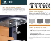
Standard Peltier PlateThe Standard Peltier Plate is the most common selection, offering an80 mm diameter hardened chrome surface to accommodate up to60 mm upper plates for maximum sensitivity.Stepped Peltier PlateThe Stepped Peltier Plate provides the convenience of interchangingplate diameters and surfaces up to 25 mm in diameter or for remotesample preparation. Stainless steel and titanium plates are availablein flat, sandblasted, and crosshatched finishes.Stepped Disposable Peltier PlateThe Stepped Disposable Peltier Plate is ideal for thermoset curingor other single-use applications and is compatible with standarddisposable plates.Dual Stage Peltier PlateThe new Dual Stage Peltier Plate is the perfect choice for applicationsrequiring sub-ambient <strong>temperature</strong> control. The unique designuses a stacked Peltier element approach, enabling fast and easy<strong>temperature</strong> control down to an unprecedented -45 °C, without theuse of expensive circulators.Peltier Plate5
peltier plateTECHNOLOGY80 mm Diameter Copper withHardened Chrome SurfacePeltier TechnologyStandard and Stepped Peltier Plates offer a <strong>temperature</strong> range of -40 °C*to 200 °C, heating rates up to 50 °C/min, and <strong>temperature</strong> accuracy of0.1 °C. Four Peltier heating elements are placed directly in contact with athin, 80 mm diameter, copper disc with an extremely rugged, hardenedchrome surface. A platinum resistance thermometer (PRT) is placed at theexact center, ensuring accurate <strong>temperature</strong> measurement and control.The unique design provides for rapid, precise, and uniform <strong>temperature</strong>control over the entire 80 mm diameter surface. This allows for accuratetesting with standard geometries up to 60 mm in diameter.* with appropriate counter coolingPeltier Heating ElementsPlatinum ResistanceThermometer (PRT)Heat Sink ConnectionsHeat Sink Fluid JacketSmart Swap BaseDual Stage Peltier Plate DesignThe new Dual Stage Peltier Plate uses a unique stacked Peltier elementdesign that offers a <strong>temperature</strong> range of -45 °C to 200 °C, with standardcounter-cooling options. It integrates a unique stacked Peltier elementconfiguration that provides enhanced low <strong>temperature</strong> responsivenessand continuous <strong>temperature</strong> control over the entire operating range witha single heat sink <strong>temperature</strong> of 2 °C. This eliminates the need to haveexpensive powerful circulators to obtain <strong>temperature</strong>s down to this range.48 mm Diameter Copper withHardened Chrome SurfaceUpper Peltier ElementPlatinum ResistanceThermometer (PRT)Upper Heat Sink JacketLower Peltier ElementsLower Heat Sink JacketSmart Swap Base6
Dual Stage Peltier Plate Cooling Test30Temperature (°C)20Unmatched cooling performance100Heat Sink = 2 ˚C-10-20-40 °C in 594 s-30-40-500 250.0 500.0 750.0 1000.0 1250.0 1500.0 1750.0 2000.0time (s)PerformancePeltier <strong>temperature</strong> control devices require that they be connected to aheat sink, typically a circulating fluid medium such as water. Most Peltier<strong>systems</strong> have a continuous <strong>temperature</strong> range of approximately 100 °Cfor a single heat sink <strong>temperature</strong>. The unique design of the Standardand Stepped Peltier Plate <strong>systems</strong> from <strong>TA</strong> <strong>Instruments</strong> extends thecontinuous range to 220 °C, as seen in data in the figure to the left. Thebenefit of this wide range is that it more than doubles the actual useable<strong>temperature</strong> range during any single test. The new Dual Stage Peltier Plateextends the low <strong>temperature</strong> limit and dramatically improves coolingperformance. The figure to the left shows that this device can reach-40 °C from room <strong>temperature</strong> in under 10 minutes with a heat sink setat 2 °C.Temperature (°C)250.0200.0150.0100.050.00Peltier Plate Temperature Steps over 220 °C RangeWidest continuous <strong>temperature</strong> rangeAdditional Temp RangeAvailable with <strong>TA</strong>Typical ContinuousTemp Range = 100 °C<strong>TA</strong> Peltier ContinuousTemp Range = 220 °CFeatures and Benefits• Unique Smart Swap technology• Wide Temperature Range: -45 °C to 200 °C• Widest Continuous Temperature Range• Accurate Temperature Control: ±0.1 °C• Hardened Chrome Surface• Standard, Stepped, and Dual Stage Models• Plates and Cones up to 60 mm in Diameter• Disposable Plates• Large Variety of Geometry Materials and Types• Fully Accessorized- Extremely Efficient Solvent Trap- Smooth, Crosshatched, and Sandblasted Covers- Purge Gas Cover- Insulating Thermal Cover- Camera Viewer Option- Immersion Cell-50.00 20.0 40.0 60.0 80.0 100.0 120.0time (min)Peltier Plate7
peltier plateGEOMETRIESSmart Swap Peltier Plate GeometriesAn extensive range of <strong>TA</strong> <strong>Instruments</strong> unique Smart Swap geometries (1) ,with automatic recognition are available for use with Peltier Plates. Conesand plates come standard in a variety of sizes, cone angles and materialtypes. Custom geometries of non-standard sizes, materials, and surfacefinishes (such as sandblasted or Teflon ® coated) are available uponrequest.(1) Patent # 6,952,950Standard Geometry DimensionsPeltier Plate geometries are available in 8 mm, 20 mm, 25 mm, 40 mm, 50 mm, and60 mm diameters. Upper Cone geometries are readily available in 0.5°, 1°, 2°, and4° cone angles. Non-standard diameters and cone angles are availableupon special request. By changing diameter and cone angle, themeasurable range of stress and strain or shear rate can be varied tocapture the widest range of material properties.Smooth Sandblasted CrosshatchedMaterials of Construction and SurfacesPeltier Plate geometries come standard in the following materials:• Stainless Steel: Rugged, very good chemical resistance for highly basicor acidic materials• Stainless Steel with Composite Heat Break: Same properties as stainlesssteel with added benefit of composite heat break, which insulates uppergeometry when controlling <strong>temperature</strong>s away from ambient• Hard Anodized Aluminum: Excellent thermal conductivity, low mass, fairchemical resistance• Titanium: Low mass, excellent chemical resistanceGeometries are available in multiple surface finishes, including smooth,sandblasted, and crosshatched.8
Peltier Plate Standard Geometry TypesPeltier Cone and Peltier Plate geometries are available in three basic types.They include geometries without solvent trap, geometries with insulatingcomposite heat break, and geometries with solvent trap. Heat breakgeometries are available in stainless steel only. Solvent trap geometriesare designed for use with the solvent trap system discussed separately. Thefigure below shows a comparison of stainless steel 40 mm geometry types.No Solvent Trap With Solvent Trap With Solvent Trap andComposite heat breakYield Stress Measurements on Toothpaste1.0E7Eliminating Wall Slip on Toothpastewith Crosshatched PlatesWall slip phenomena can have large effects on steady shear rheological1.0E61.0E5τ y=18 Paτ y=105 Pameasurements. To mitigate such issues, a roughened surface finish istypically used. The figure to the right shows the steady state flow testingresults on toothpaste with smooth and crosshatched plate geometries. Withthis type of material, standard smooth surface plates slip at the interfaceViscosity (Pa.s)100001000and lead to a false measured yield stress on the order of about 18 Pa.However, with crosshatched geometries, slip is eliminated and an accurate100.0yield stress of 105 Pa, which is more than 5 times higher, is measured.10.0Smooth plateCrosshatched plate1.01.0 10.0 100 1000Shear Stress (Pa)Peltier Plate9
peltier plateACCESSORIESWater at 40 ˚C with and without Solvent TrapPeltier Solvent Trap and Evaporation BlockerThe Solvent Trap cover and Solvent Trap geometry work in concert tocreate a thermally stable vapor barrier, virtually eliminating any solventloss during the experiment as shown in data for water at 40 ˚C to the right.The geometry includes a well that contains very low viscosity oil, or eventhe volatile solvent present in the sample. The Solvent Trap cover includes ablade that is placed into the solvent contained in the well without touchingany other part of the upper geometry. The Solvent Trap sits directly on topof the Peltier Plate surface and an insulating, centering ring insures perfectplacement for quick and easy sample loading. The solvent trap is alsoavailable in an insulated model. See Insulating Thermal Covers sectionfor details.Viscosity (Pa.s)1.0E-39.0E-48.0E-47.0E-46.0E-45.0E-44.0E-43.0E-42.0E-41.0E-4With Solvent TrapNo Solvent Trap00 20.0 40.0 60.0 80.0 100.0 120.0time (min)Solvent Trap GeometrySolvent in WellSolvent Trap CoverCentering RingPeltier PlateSample10
Purge Gas CoverThe Purge Gas Environmental Cover is a hard-anodized aluminum two-piece split cover with 6 mm diameter compression fittings. Aninsulating location ring insures precise and easy location of the cover. This cover is ideal for purging the sample area with nitrogen toprevent condensation during experiments performed below room <strong>temperature</strong> or with a humidified purge to keep a sample from drying.Insulating Thermal CoversThermal Insulation Covers are constructed of an anodized Aluminum core surrounded by an insulating exterior. The aluminum coreconducts heat to the upper geometry, providing uniform <strong>temperature</strong> throughout the sample. The cover is available in standard and solventtrap models. The standard cover accommodates up to 25 mm plates and can be used with all Peltier plate models. It is recommended foruse over a <strong>temperature</strong> range of -10 °C to 90 °C, with samples not susceptible to drying such as oils, caulk, epoxy, and asphalt binder. TheInsulated Solvent Trap Cover is compatible with the Standard Peltier Plate and geometries up to 60 mm in diameter. It is recommended fortesting of low viscosity materials over the same <strong>temperature</strong> range above and offers the added benefit of evaporation prevention. Heatbreak geometries are recommended for use with both covers.Peltier Immersion RingThe Peltier Plate Immersion Ring allows samples to be measured while fully immersed in a fluid. The immersion ring is compatible with allPeltier Plate models and is easily attached to the top of the Peltier Plate. A rubber ring provides the fluid seal. This option is ideal for studyingthe properties of hydrogels.Peltier Plate CoversA variety of Peltier Plate Covers are available for applications that can harm the chromium surface of the plate or for samples that exhibit slipduring testing. They are available in stainless steel, hard-anodized aluminum and titanium. Crosshatched and sandblasted Peltier coversare used to eliminate sample slippage effects. Covers are compatible with solvent trap.Peltier Plate Camera ViewerThe camera viewer is used in conjunction with streaming video and image capture software. Real-time images can be displayed in thesoftware and an image can be stored with each data point for subsequent viewing during data analysis. The camera viewer is perfectfor long experiments with unattended operation for visual inspections of data integrity.Peltier Plate11
upper heated plateTEMPERATURE SYSTEMUpper Heated Plate For Peltier Plate (UHP)The UHP is a <strong>temperature</strong> option designed for use with Peltierplates to eliminate vertical <strong>temperature</strong> gradients in samples.These thermal gradients can become significant above50 °C and lead to errors in absolute rheological data. The UHP isthe most advanced non-contact heating system available, usingpatented heat spreader technology (1) to deliver maximum heattransfer efficiency and patented active <strong>temperature</strong> control (2) fordirect measurement and control of the upper plate <strong>temperature</strong>. TheUHP has a maximum operating <strong>temperature</strong> of 150 °C and the lower<strong>temperature</strong> can be extended using liquid or gas cooling options.(Note: To extend the upper heated <strong>temperature</strong> range to 200 °C, seeelectrically heated plates option).Cooling &Purge InletsBand HeaterGeometry Heat SpreaderSampleATC SensorCooling ChannelUHP Heat SpreaderATC Control Point(1) Patent # 7,168,299(2) Patent # 6,931,915Peltier PlateTechnologyThe UHP sets a new standard in non-contact heating with patentedtechnologies that deliver the most accurate and reliable <strong>temperature</strong>control. A cylindrical heat transfer unit, with an integrated electric heaterand a liquid/gas cooling channel, surrounds the cylindrical heat spreadergeometry. These two components are in very close proximity, but donot contact, enabling efficient heat transfer and unimpeded torquemeasurement. Unlike competitive designs, the heat transfer unit and thegeometry heat spreader remain in constant spatial relation to one anotherregardless of the test gap, keeping heat transfer uniform at all times. Aunique calibration permits the system to match upper and lower plate<strong>temperature</strong>s at all heating rates, ensuring uniform sample heating onboth sides, virtually eliminating the need for thermal equilibrium time andenabling true <strong>temperature</strong> ramp experiments. Conventional, non-contactupper heaters require an offset calibration between the directly measuredheater <strong>temperature</strong> and the indirectly calibrated plate <strong>temperature</strong>.Patented Active Temperature Control (ATC) eliminates the need for aheater-to-plate offset table by directly measuring the upper plate<strong>temperature</strong> at all times. See ATC technology section for more details.12
KnobSecondary CoilATC SensorLower PlateMicro PCBPrimary CoilGeometry Heat SpreaderATC Sensing & Control PointUpper PlateSampleFeatures and Benefits• Unique Smart Swap technology• Wide <strong>temperature</strong> range: -30 °C* to 150 °C• Eliminates vertical <strong>temperature</strong> gradients• Patented heat spreader technology for optimum heat transfer• Substantially reduces thermal equilibrium time• Compatible with all Peltier Plate models• Patented Active Temperature Control** for significant <strong>temperature</strong>control advantages:--Only active <strong>temperature</strong> measurement and control of non-contactheating system available--Temperature known rather than inferred--No need for offset calibrations and tables--True <strong>temperature</strong> ramp capability up to 15 °C per minute--Faster <strong>temperature</strong> response compared to traditional non-contact<strong>systems</strong>• Includes sample trimming and plate removal tools• Gas purge port and environment cover• Disposable Plate system available for reactive <strong>systems</strong>• Compatible with Peltier liquid cooling, circulator, or gas coolingoptions*With appropriate cooling device**Not available with disposable platesActive Temperature Control Technology (ATC)Patented Active Temperature Control (ATC) provides non-contact <strong>temperature</strong> sensing for active measurement and control of the upper testing surface. A Platinum Resistance Thermometer (PRT) is housed withinthe special ATC draw rod. This PRT is positioned in intimate contact with the center of the upper measurement surface. The <strong>temperature</strong> signal is transmitted to a micro PCB in the knob, from which the <strong>temperature</strong>reading is transmitted through a non-contact mechanism to the rheometer head assembly. This <strong>temperature</strong> reading enables direct control of the actual upper plate <strong>temperature</strong>. Because the upper plate<strong>temperature</strong> is measured and controlled directly, the system has many advantages over traditional <strong>systems</strong>. The advantages of ATC include: more responsive <strong>temperature</strong> control, no vertical <strong>temperature</strong> gradients,and no need for inferring actual <strong>temperature</strong> from complex calibration procedures and offset tables. Together with the PRT in the lower plate, real-time control of both plates allows <strong>temperature</strong> to be changed atboth surfaces at the same rate for true <strong>temperature</strong> ramp profiles.NOTE: Active Temperature Control (ATC) is available for Upper Heated Plate (UHP) and Electrically Heated Plate (EHP) <strong>temperature</strong> <strong>systems</strong>.Upper Heated Plate13
UHP and ATCTEMPERATURE PERFORMANCESilicone Oil Viscosity Standard Response toTemperature changes in UHP10.00Material response exactly follows<strong>temperature</strong> profile110.0100.0UHP and ATC Temperature PerformanceThe true test of any rheometer <strong>temperature</strong> control system is to comparesample response to the reported system <strong>temperature</strong>. This evaluation isespecially important for a combined lower Peltier device with intimatecontact heating and an upper non-contact heating device. In this situation,the top plate heats more slowly than the bottom plate. Because the topand bottom plates heat at different rates, the sample <strong>temperature</strong> differsgreatly from the reported system <strong>temperature</strong>. In competitive <strong>systems</strong>,the sample response lags the <strong>temperature</strong> profile, requiring the user todetermine system-based thermal equilibration times and program longdelays. This issue is eliminated with <strong>TA</strong>’s unique UHP and ATC technologies,by continuously controlling and matching the upper and lower plate<strong>temperature</strong>s. This accurate response is demonstrated in the followingfigures with simple oscillation time sweep measurements.The Silicone Oil Viscosity Standard in the top figure shows that the complexviscosity response exactly follows the reported <strong>temperature</strong> profile, provingthat there is no lag between set-point and real sample <strong>temperature</strong>. Asimilar test is shown for a sample of Asphalt binder which, according tofederal standards, cannot be tested until <strong>temperature</strong> is fully equilibratedto within 0.1 °C of the set point. The asphalt data show that as soon asthe <strong>temperature</strong> is within 0.1 °C, the viscosity of the asphalt binder is fullyequilibrated and no change is seen in the viscosity even after 20 additionalminutes.By matching upper and lower <strong>temperature</strong> and heating rates, and activelycontrolling the upper plate with patented technology, <strong>TA</strong> provides the mostadvanced and accurate non-contact heating technology.|η*| (Pa.s)Temperature (˚C)1.0000.100090.080.070.060.050.040.060.0 65.0 70.0 75.0 80.0 85.0 90.0 95.0 100.0 105.07.6 min84.9 ˚Ctime (min)Asphalt Binder Response to Temperature Change in UHP90.080.070.060.050.01.000E61.000E5100001000Temperature (˚C)|η*| (Pa.s)30.07.6 min19.17 Pa.s17.8 min19.30 Pa.s27.7 min19.27 Pa.s100.020.010.000 5.0 10.0 15.0 20.0 25.0 30.0time (min)14
Advantage of UHP with Lower Peltier1.00E61.00E5Sample in Oven (ETC)Sample on Lower Peltier OnlySample with Peltier and UHPPlastisol Sample Evaluation with Upper HeatedPlateA plastisol is a mixture of resin and plasticizer that can be molded, cast,or formed into a continuous film by applying heat. Plastisols are used inapplications such as screen-printing on fabrics and ink printing, where thematerial is hardened at moderately low <strong>temperature</strong>s. The graph shows thevalue of the Upper Heated Plate (UHP) for eliminating sample <strong>temperature</strong>gradients. An oscillatory time sweep was conducted on a plastisolusing three <strong>temperature</strong> system configurations, including a combinedconvection-radiation oven, ETC, a lower Peltier Plate only, and a lowerPeltier Plate with UHP. The figure shows when the sample is surroundedby heat from the top and bottom, as in the ETC and UHP, the hardening<strong>temperature</strong>, observed as a sharp increase in G’, occurs at approximately60 °C. However, when heating the sample using only the lower Peltier Plate,the sample <strong>temperature</strong> lags behind the heating profile due to the verticalgradient, making the hardening point appear to be approximately 70 °C.G’ (Pa)1.00E41.00E3100.010.00Results in Ovenand with Peltierwith UHP AgreeTemperature (˚C)Peltier withoutUpper Heater. SampleTemperature lagsdelaying reaction.1.00020.0 30.0 40.0 50.0 60.0 70.0 80.0 90.0 100.0Temperature Response Improvement with ATC230.0ATC Performance Advantage220.0Set PointActive Temperature Control (ATC) is patented technology that enablesactive measurement and control of non-contact upper heating <strong>systems</strong>.The benefit of this technology is that it provides optimized <strong>temperature</strong>control when compared to traditional passive non-contact heating<strong>systems</strong> that require offset calibrations. The improved responsiveness ofATC is demonstrated on a polymer melt and shown in the figure to theright. A <strong>temperature</strong> step was performed on the Electrically Heated Plates(EHP) from 180 °C to 220 °C with and without ATC. The data with ATC exhibitTemperature (˚C)210.0200.0190.0With ATCsystem canheat fasterTemperatureResponsewithout ATCa faster heating rate as observed by the steeper slope, as well as a morerapid arrival to the final <strong>temperature</strong> of 220 °C.180.0170.00 100.00 200.00 300.00 400.00 500.00 600.00time (s)Upper Heated Plate15
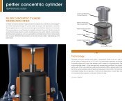
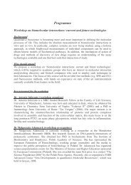
peltier concentric cylinderTEMPERATURE SYSTEMPeltier Concentric CylinderTemperature SystemThe Peltier Concentric Cylinder Temperature System combines theconvenience of Smart Swap and Peltier heating technology witha wide variety of cup and rotor geometries. Concentric Cylindergeometries are commonly used for testing low viscosity fluids,dispersions or any liquids that are pourable into a cup. Examples ofmaterials suitable for Concentric Cylinder include low concentrationpolymer solutions, solvents, oils, drilling mud, paint, varnish, inkjet ink,ceramic slurries, pharmaceutical suspensions such as cough medicineand baby formula, foams, food products such as juices, thickeners,dairy products such as milk and sour cream, salad dressings, andpasta sauce.Lower Cup GeometryContains SamplePlatinum ResistanceThermometer (PRT)Peltier Heating ElementsHeat Sink Fluid JacketHeat Sink ConnectionsSmart Swap BaseTechnologyThe Peltier Concentric Cylinder system offers a <strong>temperature</strong> range of-20 °C to 150 °C, with a maximum heating rate up to 13 °C/min. FourPeltier heating elements are placed in intimate contact with a lower cupgeometry held in place by an insulated jacket. The unique patenteddesign (1) of the lower geometry provides fast and efficient heat transfer upthe walls of the cup. A platinum resistance thermometer (PRT) is placedclose to the top of the cup ensuring accurate <strong>temperature</strong> measurementand control. The maximum controllable heating rate will depend on heatsink fluid <strong>temperature</strong>, circulator flow rate and cooling/heating capacity,and viscosity of heat sink fluid.(1) Patent # 6,588,25416
Cup and Rotor GeometeriesThe standard Peltier Concentric Cylinder geometries include a cup radius of 15 mm, configured with either a Recessed End or DIN Rotor.Both rotors have a radius of 14 mm and height of 42 mm. The double gap concentric cylinder has an additional shearing surface oversingle gap providing lower stress and higher sensitivity for extremely low viscosity solutions.Special Cups and RotorsSpecialty geometries include various vanes, helical, and starch pasting impeller rotors, as well as large diameter and grooved cups. Thesespecial concentric cylinder geometries are very valuable for characterizing dispersions with limited stability, preventing error from slip atthe material/geometry interface, and for bulk materials with larger particulates. Vane geometries are available in both a 14 mm and7.5 mm radius. The large diameter cup has a radius of 22 mm. The helical and impeller rotor and cup keep a sample mixed or particlessuspended during shearing.Double GapRotor & CupDIN Rotor &Standard CupFeatures and Benefits• Unique Smart Swap technology• Wide <strong>temperature</strong> range: -20 ˚C to 150 ˚C• Peltier <strong>temperature</strong> control for fast heating and cooling• Popular DIN standard, Recessed End and Double Gap Options• Geometries available in Stainless Steel and Hard Anodized Aluminum• Wide variety of cup diameters• Impeller and Vane geometries for preventing settling and slipping, and handling of large particles• Pressure Cell• Torsion Immersion• Special geometries available upon requestStarch PastingImpeller & CupHelical Rotor & CupVane Rotor &Grooved CupConcentric Cylinder Cup and Rotor Compatibility ChartCup/Rotor DIN Recessed Starch Vane Wide Gap Double HelicalEnd Impeller Vane Gap RotorStandard (rad= 15 mm)Large Diameter (rad= 22 mm)Starch (rad= 18.5 mm)GroovedDouble GapHelical (rad= 17 mm)Concentric Cylinder17
concentric cylinderACCESSORIES AND APPLICATIONSGeneric Container HolderThe Generic Container Holder is a Smart Swap option that can hold anycontainer with an outer diameter of up to 80 mm for characterizing materialswith rotors. This allows for quick off-the-shelf evaluation of materials, suchas paints and varnishes, creams, pasta sauce, etc., without creating largeshearing from sample loading. It also is an excellent platform for beakersor jacketed beakers.Flow Curve on Xanthan GumConcentric Cylinder geometries are useful for gathering viscosity flow curveinformation over a wide range of shear rates. An example is shown in thefigure for a Xanthan Gum solution. Five decades of viscosity are easilyobtained over six decades of shear rate. This system is also a powerfulalternative to parallel plate or cone and plate geometries for materialswith limited stability or prone to edge failure or rapid solvent evaporation.Xanthan Gum Solution in Concentric Cylinder100001001000Viscosity (Pa.s)100.010.010.0Shear Stress (Pa)1.00.100.0101.00.0010 0.010 0.10 1.0 10.0 100 1000shear rate (1/s)18
Concentric Cylinder Solvent Trap CoverA Solvent Trap is available for the Peltier Concentric Cylinder. It includes abase reservoir and a two-piece cover that is mounted to the shaft of therotor. The Solvent Trap provides a vapor barrier to seal the environmentinside the cup and prevents solvent evaporation.Two-Piece CoverBase ReservoirCupRotorFluid in ReservoirSampleCharacterization of Foam with Vane RotorThe figures below show an example of the time and frequency dependent response of a foam shaving cream characterized using a standard cup and vane geometry. The structure of shaving foam has alimited lifetime, or limited stability. The vane geometry minimizes shearing stress that occurs during loading in the gap with standard rotor, keeping the delicate foam structure intact for testing. A wide rangeof structural information can be captured very quickly using multiwave characterization on the DHR. The figure to the left shows a decay in storage modulus G’ as the structure of the foam breaks down withincreasing time. Using the multiwave, the data are simultaneously collected over a wide range of frequencies. The data can be plotted as frequency sweeps at increasing time, as shown on the right. Thesedata show the time dependent viscoelastic response of the shaving foam.Multiwave time sweepFrequency Sweeps on Foam at Different Time Intervals450.01 min20 min40 min60 minG’ (Pa)10 210 3 10 -1 10 0 10 1400.0350.0300.0G’ (Pa)250.0200.0150.0100.050.000f = 0.1 Hzf = 0.2 Hzf = 0.4 Hzf = 0.8 Hzf = 1.6 Hzf = 3.2 Hzf = 6.4 Hzf = 10 Hz0 10.0 20.0 30.0 40.0 50.0 60.0 70.0time (min)f (Hz)Concentric Cylinder19
concentric cylinderACCESSORIESTorsion Immersion CellThe Torsion Immersion Cell allows rectangular bar-shaped samples to beclamped and characterized while immersed in a <strong>temperature</strong> controlledfluid. The resulting change in mechanical properties, caused by swellingor plasticizing, can be analyzed in oscillatory experiments. This optionprovides a way to better understand materials under real-world conditions,such as body implants in saline or rubber seals in contact with oils andsolvents.Rheology of Pasta During CookingThe Torsion Immersion Cell can be used for various food applicationssuch as cooking of pasta. In this example, a piece of fettuccini pasta wastested using an oscillatory time sweep test at a frequency of 6.28 rad/s and<strong>temperature</strong> of 22 °C. Data were collected on the dry sample for 2.5 min toestablish a baseline storage modulus G’. Water was added after 2.5 minand the effect of the moisture is seen immediately as a decrease in the G’.At 5 min. G’ was monitored as <strong>temperature</strong> was ramped to 95 °C and heldisothermally. As the pasta cooks the modulus drops about three decadesand then levels out when cooking is complete.Rheology of Pasta During Cooking1.0E10Addition of water100.0Isotherm withwater at 22 ˚C90.01.0E9Isothermwith waterat 95 ˚C80.0G’ (Pa)1.0E81.0E7Temperatureramp to 95 ˚C70.060.050.0Temperature (˚C)1.0E640.030.01.0E520.00 10.0 20.0 30.0 40.0 50.0 60.0time (min)20
DHR Building Materials CellThe Building Materials Cell is a specially designed, abrasion-resistant anddurable concentric cylinder cup and rotor for testing samples with largeparticles such as concrete slurries and mixes. The paddle type rotor, slottedcage, and the large diameter cup promote adequate sample mixing whilepreventing sample slip at both the cup and rotor surfaces. The removableslotted cage permits easy sample cleaning after the test while theconcentric cylinder Peltier jacket provides accurate <strong>temperature</strong> control.Together with the existing array of specialty rotors and cups, the newBuilding Materials Cell provides the ultimate flexibility for testing a diverserange of samples with large particles including construction materials andfood products.The data below follows the structural recovery of a concrete mixture testedat 25 °C using the Building Materials Cell. The concrete sample was initiallysubject to large deformation to mimic processing conditions encounteredduring pumping. A subsequent small strain fast oscillation test simulatedthe development of the sample’s moduli following flow cessation. Theresults reveal a rapid increase in the material’s storage modulus within 10minutes, before ultimately reaching a plateau value.Paddle RotorStorage modulus G’ (Pa) Loss modulus G” (Pa)Concrete Recovery Following Pumping10 6 10 410 610 310 210 610 110 610 010 610 610 6 0 10 20 30 40 50 6010 -410 -210 -3Oscillation strain γ (%)Slotted CageLarge Diameter CupTime t (min)Concentric Cylinder21
pressure cellACCESSORYPressure Cell AccessoryThe Pressure Cell is a sealed vessel that can be pressurized up to 138bar (2,000 psi), over a <strong>temperature</strong> range of -10 °C to 150 °C. It can beused either in self-pressurizing mode, in which the pressure is producedby the volatility of the sample or by externally applying the pressurization,typically with a high pressure tank of air or nitrogen gas. Comes standardwith 26 mm conical rotor and optional vane rotor is available. All necessaryplumbing and gauges are included as a manifold assembly. The PressureCell is ideal for studying the effect of pressure on rheological properties, aswell as studying the materials that volatilize under atmospheric pressure.Outer MagnetSST ShaftLower Sapphire BearingPressure InletInternal Pressure GaugeStress Head ConnectionUpper Sapphire BearingInner MagnetPressure Relief ValueRubber SealCopper HeatTransfer SheathHollow Titanium BobSampleTechnologyThe pressure cell accessory is used with the Peltier Concentric Cylinderjacket. The sealed and pressurized volume is contained within a stainlesssteel cup to withstand high pressures and is surrounded by a coppersheath for optimal heat transfer. Also connected to the cup are thepressure inlet, internal pressure gauge, and pressure relief valve. An outermagnet assembly is attached to the rheometer drive shaft and housesstrong rare earth magnets. The rotor assembly houses the inner magnetwhich couples to, and is levitated by, the outer magnet assembly anddrives the hollow titanium cylindrical rotor. The rotor shaft is made fromlow friction Titanium nitride-coated stainless steel and is supported aboveand below by precision sapphire bearings. This innovative high-poweredmagnetic coupling and low-friction bearing design allows for both steadyshear and dynamic measurements.22
Pressure Cell RotorsThe Pressure Cell Accessory is compatible with any of three rotor designs.The standard rotor is the Conical Rotor, which is ideal for the quantitativemeasurement of liquids. Suspensions and slurries may be more well-suitedto testing using the Starch Rotor, which prevents settling, or the Vane Rotorthat is tolerant to larger particles and inhibits slip.Conical Rotor Starch Rotor Vane RotorEffect of Pressure on Viscosity of Motor Oil1.0Viscosity (Pa.s)P = Atmospheric, η = 0.31 Pa.sP = 1000 psi, η = 0.37 Pa.sP = 2000 psi, η = 0.44 Pa.sEffect of Pressure on Motor OilTo understand the ability of motor oil to provide necessary lubricationunder different environmental conditions, it is critical to know its viscosityover a range of <strong>temperature</strong>s and pressures. The figure to the left showsresults of steady state flow tests conducted on automotive motor oil. The<strong>temperature</strong> was held constant at 20 °C and tests were run at atmosphericpressure, 1,000 psi (69 bar), and 2,000 psi (138 bar) of pressure. The resultsshow that the pressure acts to increase internal friction, as observed by theincrease in viscosity.0.101.0 10.0 100 1000Shear Rate (1/s)Pressure Cell23
electrorheologyACCESSORYElectrorheology Accessory (ER)Electrorheological, or “ER”, fluids are suspensions of extremely fine nonconductingparticles in an electrically insulating fluid. These materialsshow dramatic and reversible rheological changes when the electricfield is applied. The Discovery Hybrid Rheometer ER accessory providesthe ability to characterize ER fluids up to 4,000 volts using either parallelplate or concentric cylinder geometries. The accessory is available for allDHR models and compatible <strong>temperature</strong> <strong>systems</strong> include the popularPeltier Plate (-40 °C to 200 °C) and Peltier Concentric Cylinder (-20 °C to150 °C). A custom waveform and function generator enables the user toprogram a wide range of voltage profiles directly in TRIOS Software. VoltageProfiles include: constant voltage, step voltage, ramp voltage, sine wavevoltage function, triangle wave voltage function, and wave functions withDC offsets. There are no limitations to the type or rheological experimentsthat can be performed with this accessory. A protective polycarbonateshield with trigger interlocks is also included with the accessory to providesafety from electrical shocks.Insulation BlockHigh Voltage Cablefrom TREK AmplifierMounting RingInsulating BrushGeometry InsulatorVoltage BrushInsulated GeometryPeltier PlatePeltier PlateGrounding WireFeatures and Benefits• Smart Swap technology• Easy installation and removal• Compatible with Peltier Plate and Peltier Concentric Cylinder• 25 mm and 40 mm diameter plates with ceramic insulation• 28 mm diameter DIN concentric cylinder rotor• Wide voltage range: 4000 VDC, 4000 VAC (8000 V peak to peak)• Compatible <strong>temperature</strong> <strong>systems</strong>--Peltier Plate: -40 °C to 200 °C--Peltier Concentric Cylinder: -20 °C to 150 °C• Fully programmable from TRIOS Software• Flexible voltage profile programing including:--constant voltage--step voltage, ramp voltage--sine wave voltage function--triangle wave voltage function--wave functions with DC offsets24
DC Voltage Response of a Starch in Oil Suspension200.0Step Voltage on Starch Suspension underSteady ShearA 10% starch solution in silicon oil demonstrates dramatic and reversiblechanges in structure under the application of high voltage. The figureshows time dependent viscosity with varying DC voltage, from 500 to 4000V, applied for 100 s. The underlying rheological test is a constant rate at1 s -1 , which minimizes the disturbance to the structuring process. When anViscosity (Pa.s)175.0150.0125.0100.075.0500 VDC1000 VDC2000 VDC3000 VDC4000 VDCelectrical field is applied, polarization of the starch particles in the nonconductingsilicone oil leads to stringing of the starch particles, which align50.0between the electrode plates. This orientation is responsible for the strongviscosity increase. The time to align the particles depends on the viscosity25.0of the suspending fluid and the strength of the electrical field. Becauseunder the applied shear rate, deformation of the structuring process isnot completely eliminated, a maximum viscosity is observed when the00 25.0 50.0 75.0 100.0 125.0 150.0 175.0Step time (s)dynamic equilibrium between forming and breaking of strings of alignedparticles is achieved.AC Voltage Response of a Starch in Oil SuspensionSinusoidal Voltage Oscillation under100.04000.0Steady Shear90.03000.0Electrorheological materials demonstrate interesting responses to ACvoltage profiles. The figure to the right shows the viscosity response at aconstant shear rate when an AC voltage with a peak maximum of 4000 Vand a frequency of 0.01 Hz is applied to a starch in oil suspension. Underthis applied electrical profile, it can be seen that the viscosity changes withtwice the frequency of the voltage, or put another way, is in phase with theabsolute value of the voltage. This behavior occurs because the viscosityis independent of the sign of the voltage. When the electrical field has zerovoltage, the viscosity has the lowest value.Viscosity (Pa.s)80.070.060.050.040.030.020.02000.01000.00-1000.0-2000.0ER Voltage (V)10.0-3000.00-4000.00 25.0 50.0 75.0 100.0 125.0 150.0Step time (s)Electrorheologysection title 25
26electrically heated plateTEMPERATURE SYSTEMElectrically Heated Plate (EHP)Temperature SystemThe EHP provides active heating and cooling of parallel plateand cone and plate geometries. With standard and disposable<strong>systems</strong> it’s ideal for rheological characterization of polymer meltsand thermosetting materials up to a maximum <strong>temperature</strong>of 400 °C. The optional Gas Cooling Accessory extends theminimum <strong>temperature</strong> to -70 °C. Standard features include25 mm diameter parallel plate geometry, environmental cover,and heated purge gas. An optional clear cover is available forsample viewing and for use with the Camera Viewer option. TheEHP offers Active Temperature Control (ATC) making it the onlyEHP system capable of direct <strong>temperature</strong> control of the upperand lower plates (See ATC Section for more details on this excitingtechnology). The Upper EHP can be used with lower Peltier Platesfor <strong>temperature</strong> control to 200 °C and as <strong>temperature</strong> control to150 °C for UV curing options.Purge Gas DuctUpper FixtureCooling DuctPurge Gas CoverSampleLower FixtureCooling DuctLower FixtureSmart SwapConnectorTechnologyUpper FixtureHeating ElementGeometry HeatSpreaderUpper TemperatureSensorLower PRTLower FixtureHeating ElementThe EHP lower assembly incorporates a cartridge-heater andcooling channel directly below the lower plate. A PlatinumResistance Thermometer (PRT) is positioned at the center and is incontact with the opposite face of the lower plate, providing intimatemeasurement and control of the sample <strong>temperature</strong>. In theupper assembly, a cylindrical heat transfer unit, with an integratedelectric heater and a liquid/gas cooling channel, surrounds thecylindrical heat spreader geometry. These two components arein very close proximity, but do not contact, enabling efficient heattransfer and unimpeded torque measurement. Unlike competitivedesigns, the heat transfer unit and the geometry heat spreaderremain in constant spatial relation to one another regardless ofthe test gap, keeping heat transfer uniform at all times. A uniquecalibration matches upper and lower plate <strong>temperature</strong>s at allheating rates, ensuring uniform sample heating at both sides– virtually eliminating the need for thermal equilibrium timeand enabling true <strong>temperature</strong> ramp programming. PatentedActive Temperature Control (ATC) eliminates the need for upperheater offset calibrations by providing actual measurement andcontrol of the upper plate <strong>temperature</strong>. See ATC technologysection for more details. A heated purge and cover create anoxygen-free environment around the sample to inhibit sampledegradation.
EHP Disposable PlatesFeatures and Benefits• Unique Smart Swap technology• ATC with patented Non-Contact Upper Temperature Sensor• Patented Smart Swap geometries• Maximum <strong>temperature</strong> of 400 °C• Optional low <strong>temperature</strong> cooling to -70 °C• Maximum heating rate of up to 30 °C/min• Controllable heating rates of 10 °C/min• Environmental cover and heated purge gas• Modeled for optimum heat transfer with minimum sample thermalequilibration time• Heat transfer to sample independent of gap setting• Sample trimming and plate removal tools• Disposable Plate System• Optional glass cover for sample viewing and for use with camera• Ideal for QC testing or R&D• Upper heater compatible with all Peltier Plate <strong>systems</strong> andUV Curing accessoriesControlling Polymer Degradation During TestingControlling Polymer Degradation DuringTestingViscoelastic properties of polymer melts can be affected by thermal andoxidative degradation at elevated <strong>temperature</strong>s. It is important to measurerheological properties in the absence of degradation, as well as evaluatingthe effectiveness of stabilizing additives such as antioxidants. This figureshows how effectively the EHP controls the environment for commercialpolystyrene melt during a 10-hour time sweep experiment at 200 °C. Thestorage modulus, G’, can be seen to be very stable during the early stagesof the test when the sample is purged with nitrogen. The data demonstratethe environment in the EHP is virtually oxygen-free. After about 4 hours, theinert gas is shut off and the effect of presence of oxygen on the viscoelasticresponse is seen immediately. The polystyrene degrades as evidenced bythe sharp decrease in G’.G’ (Pa)30000Nitrogen Purge OnNitrogen Purge Off2750025000225002000017500150000 100.0 200.0 300.0 400.0 500.0 600.0time (min)Electrically Heated Plate27
ETC ovenENVIRONMEN<strong>TA</strong>L TEST CHAMBEREnvironmental Test Chamber (ETC)The ETC is a high <strong>temperature</strong> Smart Swap accessory thatemploys a combination of radiant and convective heating andhas a <strong>temperature</strong> range of -160 °C to 600 °C with heating ratesup to 60 °C/min. This <strong>hybrid</strong> <strong>temperature</strong> control design providesfast response and <strong>temperature</strong> stability over a continuousrange of 760 °C. The ETC is a very popular option for polymerapplications and can be used with parallel plate, cone andplate, disposable plate, rectangular torsion clamps for solids,and the SER2 for extensional viscosity measurements. Typicalmaterials that can be tested include thermoplastics, thermosets,elastomers, caulks and adhesives, solid polymers, asphalt binder,and oils and greases.28
Oven ThermocouplePurge RingUpper GeometryHandlePlate PRTOven ClaspCeramic InsulationLower GeometryMounting BracketHeating ElementsCameraCeramic InsulationSecondary IlluminationFeatures and Benefits• Unique Smart Swap technology• No extra electronic boxes• Combined convection and radiant heating design• Wide <strong>temperature</strong> range: -160 °C to 600 °C• Maximum heating rate of 60 °C/min• Liquid nitrogen option connects directly to bulk source• Wide variety of stainless steel plates, cones, crosshatched, anddisposable geometries• Optional built-in camera viewer• Melt rings for thermoplastic pellet samples• Die punch for molded plaques• Sample cleaning and trimming tools• Extensional rheology measurements with SER2 UniversalTesting PlatformETC TechnologyThe Smart Swap ETC is a “clam-shell” design. Each half of the oven contains an electric radiant heating element surrounded by a ceramic insulation block. Air or nitrogen gas isintroduced through a purge ring with the gas flow directed over the heated coils, providing heat transfer by convection. For subambient testing, both gas and liquid nitrogen are fedthrough the purge ring. Liquid nitrogen usage is kept to a minimum by switching from gas to liquid nitrogen only when cooling is required. Temperature sensors are used both in the ovenand below the lower plates for <strong>temperature</strong> measurement and control. The ETC also features a camera viewer option installed through the chamber’s right-side ceramic block. The cameraoption features multiple light sources, remote focusing, and can be used over the entire <strong>temperature</strong> range. Used in conjunction with the streaming video and image capture software,real-time images can be displayed in the software and an image is stored with each data point for subsequent viewing. The ETC camera viewer is an ideal tool for data validation.ETC Oven29
ETCGEOMETRIESETC Geometry Accessory KitsThe ETC features five standard geometry accessory kits configured for thermoplastics and rubber, thermosetting and other curing <strong>systems</strong>, solid polymers, pressure-sensitive adhesives,asphalt binder, and extensional viscosity with the SER2 Universal Testing Platform. In addition, a wide variety of stainless steel geometries of various diameters and cone angles, and awide variety of disposable plates are available to fully accessorize the <strong>temperature</strong> system. The kits feature patented Smart Swap geometries that are automatically recognized andconfigured for use.Parallel PlateDisposable PlateTorsion RectangularTorsion CylindricalSER2 Extensional30
Air Chiller System (ACS-3)The new Air Chiller System, ACS-3, is a unique gas flow cooling system that enables <strong>temperature</strong> control of the Environmental Test Chamber to <strong>temperature</strong>s as low as -85 °C. Equippedwith a three-stage cascading compressor design, the ACS-3 allows for low <strong>temperature</strong> environmental control without the use of liquid nitrogen, instead utilizing compressed air (7 bar, 200L/min) as the cooling medium. The ACS-3 can help eliminate or reduce liquid nitrogen usage and associated hazards from any laboratory and offers an incredible return on investment.1Features and Benefits• Safe: eliminates the need for liquid nitrogen or other refrigeratedgases• Convenient: never change, refill, or order another tank of liquidnitrogen. The ACS-3 is ready to run whenever you are.• Small: occupies less space than equivalent liquid nitrogencooling <strong>systems</strong>.• Quiet: operating noise level of 55 dB• Affordable: provides considerable cost savings over recurringgas deliveries.Cooling Rate (˚C/min)2345678910-100 -90 -80 -70 -60 -50 -40 -30 -20 -10 0Temperature (˚C)ABS/PC Blend Temperature Ramp10 1010.00Low Temperature Polymer TransitionsPolymers are often blended to produce a desirable combination10 9of toughness, modulus, and processing characteristics. One suchcombination is a blend of polycarbonate (PC) with acrylonitrilebutadiene styrene (ABS). The ACS-3 provides a sufficient rangeof <strong>temperature</strong> control to characterize the multiple low and high<strong>temperature</strong> transitions of this multi-component sample. The datain the figure were collected during a <strong>temperature</strong> ramp with aG’ (Pa) G” (Pa)10 810 71.0010 -1tan (δ)rectangular specimen in torsion.10 610 5 -80 -40 0 40 80 120 16010 -2Temperature (˚C)ETC Oven31
ETC and EHPPOLYMER APPLICATIONSThemoplastic Polymer Rheology UsingPolystyrene Frequency Sweeps from 160 ˚C to 220 ˚CParallel Plate1.0E6Extended Frequency Range with TTS1.0E6Parallel Plate geometries are most popular for testing of thermoplasticReference Temperature = 210 ˚Cpolymer melts. An example of polystyrene characterized over a <strong>temperature</strong>1.0E51.0E5range of 160 °C to 220 °C is shown in the figure to the right. Frequency sweepswere run at multiple <strong>temperature</strong>s over an experimental range of 0.06 to 628rad/s. The magnitude of the viscoelastic properties, storage modulus (G’)1000010000and loss modulus (G”), for the individual sweeps can be seen to decreasewith increasing <strong>temperature</strong> over this frequency range. Since polymermelts are viscoelastic, their mechanical response will be time dependent,G’ (Pa)10001000G” (Pa)so low frequency corresponds to long time behavior. Time TemperatureSuperposition (TTS) is used to widen the range of data to higher and lowerfrequencies and generate a Master curve at a reference <strong>temperature</strong>pertinent to the application. The polymer’s molecular structure dictates the100.0ExperimentalFrequency Range100.0magnitude and shape of the G’ and G” curves.10.010.00.010 0.10 1.00 10.0 100.0 1000 10000 1.0E5ω (rad/s)Themoset Cure Using Disposable Plate KitChanges in the viscoelastic properties of reactive <strong>systems</strong> provide valuableinformation about their processing and end-use properties. Often thesematerials can start in the form of a low viscosity liquid, a paste, or evena powder, and after reacting end as a high modulus solid. If the materialhardens and adheres to the testing surface, low-cost disposable parallelplates are required for testing. The figure to the right shows the complexviscosity from a typical oscillatory <strong>temperature</strong> ramp and hold curing testconducted on a B-stage prepreg using 25 mm diameter disposable plates.The resin is impregnated on a woven glass matrix, which becomes part ofthe permanent high strength composite structure once the resin is cured.Upon heating, the resin softens until reaching a minimum viscosity, whichis a very important processing parameter. If the viscosity is too high or toolow, the resin will not flow or coat the matrix uniformly leaving voids, creatingflaws in the composite. Eventually the viscosity starts building and the curingreaction takes off dramatically. The <strong>temperature</strong> is held constant at theprocessing <strong>temperature</strong> and the viscosity is monitored until the viscosityreaches a plateau indicating the completion of the reaction.|η*| (Pa.s)1.0E71.0E61.0E5B-Stage Prepreg Temperature Ramp and Hold CureTemperatureRamp StepSofteningMinimumViscosityIsothermal Step200.0175.0150.0125.0100.01000025.00 20.0 40.0 60.0 80.0 100.0 120.0time (min)CuringReactionFinal Cure75.050.0Temperatrure (˚C)32
ABS Oscillation Temperature Ramp in Torsion RectangularSolid Polymer Rheology Using TorsionRectangular ClampsThe ETC oven has the ability to characterize the viscoelastic properties ofrectangular solid samples up to 5 mm thick, 13 mm wide, and 50 mm long.The figure to the right shows an example of an oscillatory <strong>temperature</strong> scanon a solid ABS specimen run at 3 °C/min from -160 °C to 200 °C. The ABS isa copolymer that exhibits two glass transition <strong>temperature</strong>s: one at -81 °Cassociated with the Butadiene and one at 114 °C associated with Styrene.Transitions, or relaxations of molecular segments, are observed as stepchanges in the storage modulus (G’) and as peaks in the loss modulus (G”)and damping (tanδ). The magnitude and shape of these parameters willdepend on chemical composition as well as physical characteristics (suchas crystallinity, orientation, fillers, and degree of cross-linking).G’ (Pa)1.0E101.0E91.0E81.0E71.0E61.0E5ButadieneTg = -81.2 ˚CFrequency: 6.28 rad/sRamp Rate: 3 ˚C/minStyreneTg = 114 ˚C10.001.0000.10000.010001.000E-3-200.0 -150.0 -100.0 -50.0 0 50.0 100.0 150.0 200.0Temperature (˚C)tan(delta)1.0E101.0E91.0E81.0E71.0E61.0E5G”(Pa)SER2 compared to shear viscosity dataExtensional Viscosity measurements with theSER2 attachmentThe ETC is designed to accommodate the SER2 (Sentmanat Extension1.0E6LDPE 1810HT=150 ˚CRheometer) for extensional viscosity measurements of polymer melts. In thefigure to the right, data are plotted for extensional viscosity measurementsof standard LDPE 1810H at 150 ˚C at extensional rates from 0.02 to 3 s -1 usingthe SER2. These results are compared to three times the corresponding lowshear rate viscosity, which agrees well with the zero rate extensional viscosityprior to the onset of extensional thickening at different extension rates. Inaddition to extensional viscosity, the SER2 can also be used for solids tensiletesting, tear testing, peel testing, friction testing, as well as high-rate fracturetesting.Viscosity η E(Pa.s)1.0E5100003x shear viscosityElongation rate (s -1 )0.020.10.31.03.010000.01 0.1 1 10 100 1000time (s)EHP and ETC Polymer Applications33
dielectric measurementACCESSORYBNC Connectionsto LCR MeterWire to Upper PlateDielectric AccessoryThe Dielectric Accessory, available for all DHR models, extendsmaterial characterization capabilities by providing an additionaltechnique similar to dynamic mechanical. In dielectric analysis,an oscillation electrical field (AC Field) is used as opposed tomechanical force (stress) and the oscillating strain is a storedcharge (Q) in the sample. The technique measures the degreeto which the sample is storing a charge (capacitance) or passinga charge (conductance) through its bulk. The DHR provides aflexible platform for easy test setup and calibration, and dataaccuracy through standard features such as the EnvironmentalTest Chamber, axial force control, and gap <strong>temperature</strong>compensation routines. Dielectric analysis is a very powerfultechnique for characterizing polar materials such as PVC, PVDF,PMMA, and PVA, for phase separating <strong>systems</strong>, and for monitoringcuring kinetics of materials such as epoxy and urethane <strong>systems</strong>.Dielectric analysis extends the measurable frequency range overtraditional dynamic mechanical analysis which is typically limitedto 100 Hz.Ground Geometry withCeramic InsulationSmart SwapConnectionWire to Lower PlateBNC Connectionsto LCR MeterTechnologyDielectricAccessoryMountThe Dielectric accessory consists of a special set of 25 mm parallelplates that are fitted with wiring and hardware for interfacing witha dielectric LCR meter (Agilent Model E4980A LCR) that imposes asignal at a certain voltage and frequency/ies. The voltage rangeavailable is between 0.005 to 20 V with a frequency range of 20Hz to 2 MHz. The Environmental Test Chamber (see page 24)provides <strong>temperature</strong> control at a range of -160 °C to 350 °C. Theaccessory allows for the simultaneous collection of rheologicaland dielectric information, or dielectric measurements can berun independently.34Features and Benefits• Smart Swap technology• 25 mm diameter plates with ceramic insulation• Disposable plates for curing system• Stand-alone dielectric measurements• Combined rheological and dielectric measurements• Fully programmable from TRIOS Software• Time-Temperature Superposition• Master curve generation• Wide dielectric frequency range: 20 Hz to 2 MHz• Easy installation and removal• Compatible with ETC over a <strong>temperature</strong> range of-160 °C to 350 °C• USB Interface
Phase Separation in Cosmetic CreamsTemperature stability of materials such as food and cosmeticsis very important for product performance in storage andtransportation. Rheological testing is widely used for stabilityevaluations; however, the ability to simultaneously measuredielectric properties can provide more valuable insight forcomplex formulations. An example is shown in the figure to theright for two water-based cosmetic creams tested by cooling from25 °C down to -30 °C. In comparing only storage modulus, G’,data of the two materials, the POND’S ® cream shows little increasefollowed by a three decade jump at -18 °C, but NIVEA creamexhibits a more continuous change in the modulus over the entire<strong>temperature</strong> range. One may conclude from the mechanicalresponse alone that the large jump in G’ of POND’S at -18 °Cis associated with instability. However, having the simultaneousmeasurement of the loss permittivity, ε”, provides informationrelating to the change in ion mobility; primarily of the water phasein these samples. In the ε” the NIVEA shows a two decade jumpcompared to very little change in the ε” of the POND’S. The largeincrease in ε” is due to increased ion mobility in the material as thewater separates. In the final analysis, phase separation occurs inthe NIVEA, not the POND’S. During the cooling process, as phaseseparation gradually occurs, the water phase grows changingthe morphology. As the morphology gradually changes, so toodoes the G’. The large change in G’ of the POND’S is the result ofa transition of a more stable and uniform morphology.Simultaneous Dielectric and Rheology of Hand Creams on FreezingStorage modulus (Pa)10 810 710 610 510 410 3 -40 -30 -20 -10 0 10 20 3010 -130.0ε’Temperature (˚C)POND’S creamNIVEA creamCooling rate: 3 ˚C/minMechanical Frequency: 1 HzDielectric Frequency: 200 HzDielectric Temperature Ramp on PMMA10 710 610 510 410 310 210 110 00.1750.15Loss permittivity ε” (pF/m)Dielectric Temperature Rampat Multiple FrequenciesThe figure to the right shows a <strong>temperature</strong> ramp on a Poly(methyl methacralyte), PMMA, sample at four different dielectricfrequencies ranging from 1,000 Hz to 1,000,000 Hz. It can beseen here that the magnitude of ε’ decreases with increasingfrequency through the transition region and the peak of theStorage permittivity ε’ (pF/m)15.00-15.01000 Hz10000 Hz100000 Hz1000000 Hztan δ0.1250.10.0750.05tan (δ)transition in tan d moves to higher <strong>temperature</strong>s with increasing0.025frequency.-30.0025 50 75 100 125 150 175 200 225Temperature (˚C)section Dielectric title 35
interfacial rheologyACCESSORIESInterfacial AccessoriesRheometers are typically used for measuring bulk or threedimensionalproperties of materials. In many materials, suchas pharmaceuticals, foods, personal care products andcoatings, there is a two-dimensional liquid/liquid or gas/liquid interface with distinct rheological properties. Only <strong>TA</strong><strong>Instruments</strong> offers three separate devices for the most flexibilityand widest range of quantitative measurements for thestudy of interfacial rheology. The options include a patentedDouble Wall Ring (DWR) system for quantitative viscosity andviscoelastic information over the widest measurement ranges, aDouble Wall Du Noüy Ring (DDR) for samples available inlimited volumes, and a traditional Bicone for interfacial viscositymeasurements.Interfacial Viscosity (Pa.s.m)10 010 -110 -210 -310 -410 -510 -6BiconeMolecules/nm 2water0.360.91.441.83.67.2Double Wall Du NoüyRing (DDR)surface loading10 -7 10 -4 10 -3 10 -2 10 -1 10 0 10 1 10 2 10 3.Shear rate γ (1/s)36ApplicationIn this series of tests, the surfactant SPAN65 was spread evenlyat the water-air interface using a solution of SPAN in chloroform.After the evaporation of the chloroform, the SPAN65 filmdeposited on the water was measured using the Double WallRing Interfacial accessory. Different loadings of surfactant weretested from 0 (just water, no surfactant layer) to 7.2 moleculesper nm 2 . Continuous shear experiments were conducted andthe interfacial viscosity was measured as a function of shearrate and interfacial concentration. As expected, the surfactantlayer shows significant shear thinning. At high rates, thesub-phase contributions dominate for the loadings less than1.8 molecules/nm 2 . Sub-phase correction becomes importantbelow an interfacial viscosity of 10 -5 Pa.s.m and the well-definedgeometry of the DWR makes these quantitative sub-phasecorrections possible. At higher interfacial viscosities, sub-phasecontributions are negligible and the correction is unnecessary.
TechnologyIn all <strong>TA</strong> <strong>Instruments</strong> interfacial rheology <strong>systems</strong>, the sample is contained in a Delrin® trough complete with fluid level monitoring windows and injection ports. The measuring rings of theDouble Wall Ring (DWR) and Double Wall Du Noüy Ring (DDR) geometries are made of platinum-iridium. These materials are selected for their inert chemistry and ease of cleaning. <strong>TA</strong><strong>Instruments</strong> is the only supplier offering patented double wall geometry configurations that provide interfacial shear planes on both sides of the geometry surface for higher sensitivity tothe monolayer viscoelastic response.Only the DWR is capable of truly quantitative viscoelastic parameters because the interface is “pinned” to the diamond-shaped cross-section of the geometry ring. This patented ultra-lowinertia ring (1) has a diameter of 60 mm and was designed for ease-of-use and maximum sensitivity. Surface viscosity measurements can be conducted on surface viscosities as low as 10 -5Pa.s.m without complicated sub-phase corrections. And, oscillation measurements are possible over the widest frequency range of any interfacial system.The du Noüy ring geometry of the DDR is an industry standard device used for surface tension measurements. The round cross-section allows for meniscus formation between the interfaceand geometry, creating a slight error in the absolute data. With a much smaller diameter of 20 mm, this system is ideal for testing interfacial properties of samples that are available invery limited quantities, such as biological or pharmaceutical materials.The Bicone is a double conical stainless steel geometry with a sharp edge that reproducibly pins the interface. Because of the large drag created by the surface of the cone submergedwithin the sub-phase, large corrections are required to obtain quantitative parameters. The geometry’s large moment of inertia limits measurement capability to interfacial viscosity insteady shear mode, precluding valuable measurements of quiescent structure and elasticity.(1) Patent # 7,926,326Pt-Ir RingInterfacePt-Ir RingInterfaceBiconeInterfaceInterfacial ShearDiamond-Shaped RingInterfacial ShearRound RingInterfacial ShearDouble Wall Ring (DWR) Cross-SectionDouble Wall Du Noüy Ring (DDR) Cross-SectionBicone Cross-SectionInterfacial37
small angle light scatteringACCESSORYUpper AssemblyMountingSmall Angle Light Scattering (SALS)The Small Angle Light Scattering (SALS) System is an option forsimultaneously obtaining rheological and structural information,such as particle size, shape, orientation and spatial distribution.It is available for the DHR-3 and DHR-2 Rheometers. The optionincorporates <strong>TA</strong> <strong>Instruments</strong>’ Smart Swap technology, bringinga new level of speed and simplicity for making simultaneousrheology and SALS measurements. The system can be installed,aligned, and ready for measurements in as little as five minutes.It features patented Peltier Plate <strong>temperature</strong> control (1) and thescattering angle (θ) range over which measurements can be madeis ~ 6° to 26.8°. The scattering vector range (q) is 1.38 μm -1 to 6.11μm -1 and the length scale range is about 1.0 μm to ~ 4.6 μm.Quartz PlatePeltier PlateCamera ChipPinholeLensesSapphire WindowLaserSmart Swap BaseTechnologyThe SALS accessory consists of upper and lower assemblies andquartz plate geometry. The lower assembly includes an integratedClass 2 laser (with 0.95 mW diode and wavelength λ = 635 nm)situated below a patented (1) Peltier Plate with a 5 mm diameterquartz window. The Peltier Plate surface is stainless steel with a<strong>temperature</strong> range of 5 °C to 95 °C. The upper assembly consistsof a set of lenses and a camera. The scattered light is focusedthrough a lens pair mounted within a height-adjustable cap tofocus at varying sample depths. The light is then focused througha second lens and sent through an adjustable polarizer for bothpolarized and depolarized measurements. Finally, the scatteringis collected through a pinhole and recorded by the camera. Theupper geometry is a 50 mm diameter, 2 mm thick optical quartzdisk. To comply with the single-point correction for the parallelplates, the laser is set at 0.76 times the plate radius which is 19 mmfrom the axis of rotation of the plate. This arrangement keeps theSALS system compact, while allowing for quick and reproduciblepositioning and focusing. A set of neutral density filters is availableas an option to reduce laser intensity.(1) Patent # 7,500,38538
Features and Benefits• Smart Swap technology• q vector range ~1.38 μm -1 to 6.11μm -1• Objects length scale range ~ 1 μm to 4.6 μm• Scattering angle ~ 6° to 26.8°• Wavelength 635 nm• Compact upper assembly requiring minimal adjustment• Smart Swap lower assembly with factory aligned laser• Class 2 laser - No safety issues• Adjustable laser intensity with optional neutral density filters• Variable depth focus to adjust for different geometry gaps• Adjustable polarizer for scattering in parallel or perpendicularto the incident light• Image focused directly onto camera chip – Does not requirescreen or darkened room• Quantitative measurements possible by calibration withmonodisperse Polystryrene beads.• Optional Analysis Software• Patented Peltier Plate <strong>temperature</strong> controlScattering Images Captured with Rheometry DataShear-Induced Phase Separationof Micellar Solutions70Self-assembled surfactant micelles show a variety of shear-605040induced microstructural transformations that are important formaterial formulation and function for a wide array of applications.Simultaneous measurements of rheology and surfactantShear Stress (Pa)3020Flow direction10 s -120 s -1 30 s -1microstructure, using SALS under shear, provides a valuable toolin examining shear-induced transitions in such fluids. The data inthe figure show scattering images captured synchronously withrheometry data on a surfactant system. At low shear rates belowthe stress plateau, no measurable scattering is obtained from10the sample, suggesting no large-scale structuring of the fluid.50 s -1 100 s -1 200 s -1However, in the stress plateau, a strong anisotropic scattering10 100pattern develops with increasing shear rate. This “butterfly” patternShear Rate (s -1 )results from phase separation, where the interface between thetwo phases generates a strong scattering contrast.Small Angle Light Scattering39
UV curingACCESSORIESUV Curing AccessoriesUV-curable materials are widely used for coatings, adhesives,and inks. When these materials are exposed to UV radiation,a fast cross-linking reaction occurs, typically within less thana second to a few minutes. Two Smart Swap accessories forrheological characterization of these materials are available forthe DHR-3 and DHR-2 <strong>rheometers</strong>. One accessory uses a lightguide and reflecting mirror assembly to transfer UV radiation froma high-pressure mercury light source. The second accessory usesself-contained light emitting diodes (LED) arrays to deliver lightto the sample. Accessories include 20 mm quartz plate, UV lightshield, and nitrogen purge cover. Optional <strong>temperature</strong> controlto a maximum of 150 °C is available using the Electrically HeatedPlates (EHP) option. Disposable plates are available for hard UVcoatings, which cannot be removed from the plates once cured.20 mm Diameter Quartz PlateCoverMirrorCollimatorSmart Swap BaseLight Guide SocketUV Light Guide Accessory TechnologyThe UV Light Guide accessory includes a lower Smart Swapassembly with quartz plate, light source mount, collimator, 5mm diameter light guide, and UV mercury lamp source (ExfoOmnicure S2000). It provides a broad wavelength spectrum from250 nm to 600 nm, with a primary peak at 365 nm. The maximumoutput intensity is greater than 300 mW/cm 2 . External filter holderand filters are available for the light source.Features and Benefits• Smart Swap technology• Convenient compact• Collimated light and mirror assembly insure uniform irradianceacross plate diameter• Maximum intensity at plate 300 mW/cm 2• Broad range spectrum with main peak at 365 nm• One system with specific wavelengths accessible throughfiltering options• Cover with nitrogen purge ports• Optional disposable acrylic plates• Optional <strong>temperature</strong> control to 150 ˚C• Software programmable trigger time and intensity40
Purge Gas PortCoverSmart Swap BaseUV LED Accessory Technology20 mm DiameterQuartz PlateWater JacketFeatures and Benefits• Smart Swap technology• New technology replaces mercury bulb <strong>systems</strong>• 365 nm wavelength with peak intensity of 150 mW/cm 2• 455 nm wavelength with peak intensity of 350 mW/cm 2• No intensity degradation over time• Even intensity across plate diameter, LED positioned directlybelow plate• Compact and fully integrated design including power, intensitysettings and trigger• Cover with Nitrogen purge ports• Optional disposable Acrylic plates• Optional <strong>temperature</strong> control to 150 ˚CThe UV LED accessories use arrays of light emitting diodes that provide single peak wavelength light sources.The LED array is mounted on a PCB and is fixed to a water jacket that cools the LED’s during use. Like the UVlight guide system, LED’s are pre-aligned to insure uniform irradiance across the surface of the plate. Thereare two LED accessories available at wavelengths of 365 nm and 455 nm. The maximum output UV intensityis 150 mW/cm 2 and 350 mW/cm 2 , respectively. They are fully integrated with the rheometer through a SmartSwap option. Trigger time and intensity are conveniently programmed through the software.|G*| (Pa)1.0E71.0E61.0E5100001000100050mW/cm 2100mW/cm 2150mW/cm 220Effect of UV Curing Intensity40G’(Pa)1.000E5100001000100.028.000 29.000 30.000 31.000 32.000 33.000 34.000 35.00060time (s)time(s)80IncreasingIntensity1001000E5100001000100.0G”(Pa)120.0UV Accessory ApplicationThese accessories allow the study of UV curing reactions bymonitoring the elastic (G’) and viscous (G”) moduli. The exampleon the left shows results of a pressure sensitive adhesive, (PSA),characterized with the UV Light Guide Accessory. The PSA washeld at an isothermal <strong>temperature</strong> of 25 °C and the curingprofile was measured at radiation intensities from 50 mW/cm²to 150 mW/cm². The sample is measured for 30 seconds beforethe light is turned on. The data show faster reaction kineticswith increasing intensity, as evidenced by the shorter time forcrossover of G’ and G”. Similar results can be obtained withcontrolled <strong>temperature</strong>, where the reaction is seen to occur morequickly at higher <strong>temperature</strong>s. The curing reaction happens inless than two seconds. The fast data acquisition of the DiscoveryHybrid Rheometers (up to 50 pts/sec) enables clear identificationof the liquid to solid transition. Note that changing the intensityand <strong>temperature</strong> by small amounts shifts the crossover pointby a fraction of a second. This information is important forunderstanding adhesive control parameters for high-speed UVcuring processes, as well as for understanding differences ininitiators when formulating materials.UV Curing41
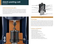
starch pasting cellACCESSORYLocking CoverWater InStarch Pasting Cell (SPC)The Starch Pasting Cell (SPC) provides a more accurate andpowerful tool to characterize the gelatinization of raw andmodified starch products, as well as the properties of the starchgels. It can also be used for characterizing many other highlyunstable materials. It uses an innovative impeller design formixing, reduction of water loss, and control of sedimentationduring testing. The actual sample <strong>temperature</strong> is measured andcontrolled in a <strong>temperature</strong> chamber with heating/cooling ratesup to 30 °C/min.ImpellerCooling Water ChannelTemperature SensorHeater ElementCupWater OutSmart Swap BaseTechnologyThe SPC consists of the cell jacket, an impeller, and aluminumcup with locking cover. The cell jacket houses a heating coil andliquid cooling channel, which surrounds the Aluminum cup forfast heating and cooling. A Platinum Resistance Thermometer(PRT) is located in intimate contact with the bottom of the cup forprecise and accurate sample <strong>temperature</strong> control. The impelleris designed with blades at the bottom for sample mixing. Solventloss is minimized via a conical ring at the top of the rotor, whichacts to condense water (or other solvents) that vaporizes duringheating, and return it to the bulk sample.Features and Benefits• Smart Swap technology• Heating/Cooling rates up 30 °C/min• Higher accuracy for greater reproducibility• Robust Cup and Impeller• Impeller keeps unstable particles suspended inliquid phase during measurements• Impeller design minimizes loss of water or other solvents• Sample <strong>temperature</strong> measured directly• All rheometer test modes available for advancedmeasurements on gelled starches and other materials• Optional conical rotor for traditional rheological measurements42
Gelatinization of Starch ProductsStarch is not only a food product; functionally modified starchesare widely used in the industry including adhesives, paper,coatings, wood, packaging, pharmaceutical, and manyothers. When starch is heated above a critical <strong>temperature</strong>,the starch granules undergo an irreversible process, known asgelatinization. The properties of the starch gels depend on theorigin of the raw starch (crop, potatoes, etc.), the environmentalconditions (seasons) or the modification. The viscosity curve,referred to as pasting curve, produced by heating and coolingstarches generally has a similar characteristic shape. The figureto the right shows two scans each of both a Dent Corn and WaxyMaize starch. The benefit of the DHR starch cell design can easilybe observed in the unprecedented reproducibility of the pastingcurves for these two starch products.Viscosity (Pa.s)Two Scans each of Dent Corn and Waxy Maize Starch2.0100.090.01.580.070.01.060.050.00.5Dent Corn Starch40.0Waxy Maize Starch030.00 250.0 500.0 750.0 1000 1250 1500 1750 2000 2250time (s)Temperature (˚C)Advanced Starch RheologyIn addition to measuring the characteristic pasting curve ofDent Corn Starch Gelatinizationstarch products, the starch cell brings new testing capabilitiesfor measuring properties of the starch gels. The figure to theright shows additional data obtained on Dent Corn starchusing an oscillation test to monitor the gelation process of thestarch under negligible shearing. In this test, the sample issheared while ramping <strong>temperature</strong> to keep starch particlessuspended. At 75 °C, when the viscosity is high enough to inhibitparticle settling, the steady shear was stopped and testing wascontinued at a small oscillating stress. The figure shows storagemodulus, G’, and the loss modulus, G”. which provide extremelysensitive information about the structural characteristics of theDynamic moduli (Pa)7550250G’ [Pa]G” [Pa]Temperature1251007550Temperature (˚C)starch gelation and final gel. This enables the development ofvaluable structure-property relationships. The ability to makethese sensitive measurements is not possible on traditional starchcharacterization instrumentation.-2525200 400 600 800 1000 1200 1400time (s)Starch Pasting Cell43
tribo-rheometryACCESSORYTribologyTribology is defined as the study of interacting surfaces undergoingrelative motion. The new Tribo-Rheometry Accessory, availablefor all DHR models, enables the capability to make coefficientof friction measurements between two solid surfaces under dryor lubricated conditions. The unique self-aligning design ensuresuniform solid-solid contact and axial force distribution under allconditions. A modular set of standard and novel geometries offersa choice of different contact profiles and direct simulation ofend-use conditions. Accurate and precise control of axial force,rotational speed, and <strong>temperature</strong> inherent to <strong>TA</strong> Instrument<strong>rheometers</strong> provides for the best and widest range of frictionmeasurements.Features and Benefits• Compatible with Stepped Disposable Peltier Plate andEnvironmental Test chamber• Characterize materials wear and coefficient of friction underdry or lubricated conditions• Unique self-aligning design for best solid-solid contact• Modular set of geometries offers choice of contact profiles• Interchangeable parts for customized substrates• Automatic software calculation of relevant friction parameters• Easy installation and removalThe advanced TRIOS software offers easy setup and control oftribo-rheometry tests and contains a complete set of variablesrequired for data analysis including the coefficient of friction(μ), load force (F L), friction force (F F) and Gumbel number (Gu).These may be used to construct Stribeck curves, static frictionmeasurements, or explore specific combinations of <strong>temperature</strong>,contact force, and motion.44
Ring on PlateBall on three platesBall on Three BallsThree Balls on PlateThe accompanying figure shows the coefficient of friction profiles of twocommercially available toothpastes tested between textured PMMA plates(acting as tooth substitutes) using the ring on plate configuration. Thewhitening toothpaste, with abrasive particles, has higher friction at lowspeeds, but the gel toothpaste’s friction profile shows a rapid increaseat higher speeds. This behavior can be explained by comparing the flowcurves of the two toothpastes – although both materials are shear thinning,the viscosity of whitening toothpaste decreases more rapidly than thegel toothpaste. This results in increased hydrodynamic drag and greaterfriction at higher rotation speeds.The Tribo-Rheometry Accessory is compatible with both the SteppedDisposable Peltier Plate and the Environmental Test Chamber (ETC) foraccurate and stable <strong>temperature</strong> control for all test geometries. The choiceof four standard geometries – Ring on Plate, Ball on Three Plates, ThreeBalls on Plate, and Ball on Three Balls – meets the diverse requirements1.11.0Gel ToothpasteWhitening Toothpaste10 410 3of tribology applications and offers a variety of contact profiles. The ringon plate geometry may also be configured as a partitioned ring, whichpermits the replenishment of lubricant between the two solid surfaces.The accessory’s versatile configurations and easily interchangeablesubstrates are ideal for studying the effect of friction and long-term wear onmaterials ranging from automotive components and greases, lubricationin prosthetic devices, and the performance of personal care creams andCoefficient of Friction0.90.80.70.60.510 210 1Viscosity (Pa.s)lotions.0.40.310 00 10 -2 10 -1 10 0 10 1Velocity (rad/s)Tribology45
NOTESPOND’S ® is a trademark of Conopco, Inc.NIVEA is a trademark of Beiersdorf AG.Teflon ® and Delrin ® are trademarks of E.I. du Pont de Nemours and Company.Swap Smart and <strong>TA</strong> <strong>Instruments</strong> ® are trademarks of <strong>TA</strong> <strong>Instruments</strong>.
New Castle, DE USALindon, UT USAHüllhorst, GermanyShanghai, ChinaBeijing, ChinaTokyo, JapanSeoul, South KoreaTaipei, TaiwanBangalore, IndiaSydney, AustraliaGuangzhou, ChinaHong KongEschborn, GermanyWetzlar, GermanyBrussels, BelgiumEtten-Leur, NetherlandsParis, FranceElstree, United KingdomBarcelona, SpainMilano, ItalyWarsaw, PolandPrague, Czech RepublicSollentuna, SwedenHelsinki, FinlandCopenhagen, DenmarkChicago, IL USASão Paulo, BrazilMexico City, MexicoMontreal, Canada
tainstruments.com© 2014 <strong>TA</strong> <strong>Instruments</strong>. All rights reserved. L50016.001