Specification - Watts Fluid Air
Specification - Watts Fluid Air
Specification - Watts Fluid Air

Create successful ePaper yourself
Turn your PDF publications into a flip-book with our unique Google optimized e-Paper software.
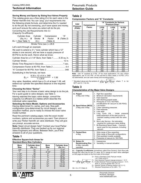
Catalog MRO-6WATechnical InformationSaving Money and Space by Sizing Your Valves ProperlyThis catalog gives you a flow rating (Cv) for each valve in theParker Hannifin line. You can “plug” your requirements intothe following simple formula, and determine the Cv neededto do the job. By not oversizing, you’ll save space and money,and you’ll ensure the valve you select will do the job.Converting the Job Requirements Into Cv(Capacity Co-efficient).Cylinder Area Cylinder Compression “A”(Sq. In.) X Stroke X Factor X (Table 2)Cv = (See Table 1) (In.) (Table 2)Stroke Time (sec.) x 28.8Let’s work through an example:We want to extend a 3 1 / 4" bore cylinder which has a 12"stroke in one second, and we have a supply pressure of80 PSI to do the work. Here’s what we know:Cylinder Area for a 3-1/4" Bore, from Table 1.........8.30 sq. in.Cylinder Stroke................................................................ 12 in.Stroke Time Required in Seconds...................................1 sec.Compression Factor at 80 PSI, from Table 2....................... 6.4“A” Constant for 80 PSI, from Table 2................................ .048Substituting in the formula, we have:8.30 x 12 x 6.4 x .048Cv == 1.061 x 28.8Any valve, therefore, which has a Cv of at least 1.06, willextend our cylinder the specified distance in the requiredtime.Choosing the Valve “Series”Your next step is to choose a basic valve design to do the job.For a quick guide to valve designs, see Table 3.Having selected the basic valve design, consult theCapacity Co-efficient (Cv) tables which describe theindividual valve capacities.Selecting the Valve Model, Options and AccessoriesHaving determined Cv, series, port size, flow-pathconfiguration (pre-determined by circuit design), andactuation method, you’re ready to choose the exact valvemodel number.Read the pertinent catalog pages; note the exact modelnumbers, options and accessories you want. Then phone orwrite your Parker Hannifin air valve distributor. They will giveyou prompt, accurate service.Note: Need circuit design help? Contact your local ParkerHannifin distributor. They are backed up by our regionalSales Engineers and offices. Between them, you’ll findanswers to all of your questions.Table 1Effective Square-Inch Areas forStandard-Bore-Size CylindersBoreSizeCylinder Area(Sq. In.)BoreSizeCylinder Area(Sq. In.)3/4" .44 4" 12.571" .79 4-1/2" 15.901-1/8" .99 5" 19.641-1/4" 1.23 6" 28.271-1/2" 1.77 7" 38.481-3/4" 2.41 8" 50.272" 3.14 10" 78.542-1/2" 4.91 12" 113.103-1/4" 8.30 14" 153.943-5/8" 10.32Pneumatic ProductsSelection GuideTable 2Compression Factors and “A” ConstantsInletPressure(PSIG)CompressionFactor“A” Constants for VariousPressure Drop*2 PSIrP5 PSIrP10 PSIrP10 1.6 .152 .103 —20 2.3 .126 .084 .06530 3.0 .111 .073 .05540 3.7 .100 .065 .04850 4.4 .091 .059 .04460 5.1 .085 .055 .04070 5.7 .079 .051 .03780 6.4 .075 .048 .03590 7.1 .071 .046 .033100 7.8 .068 .044 .032110 8.5 .065 .042 .030120 9.2 .063 .040 .029130 9.9 .061 .039 .028140 10.6 .058 .037 .027150 11.2 .057 .036 .026160 11.9 .055 .035 .025170 12.6 .053 .034 .024180 13.3 .052 .033 .024190 14.0 .051 .032 .023200 14.7 .050 .032 .023Note: Use “A” constant at 5 PSI rP for most applications. On very criticalapplications, use “A” at 2 PSI rP. You will find in many cases, a 10 PSI rP isnot detrimental, and can save money and mounting space.1 GT* Tabulated values are the solution of where T is for22.48 (P 1– P 2) P68°F and G =1 for <strong>Air</strong>.2Table 3Characteristics of the Major Valve DesignsA. Poppet 1. High flow capacities3-Way and 4-Way 2. Minimum lubrication requirements3 . Fast response4 . Self-cleaning poppet seats5 . Pressures of 15 to 150 PSIG(modifications for vacuum to 250 PSIG)B. Spool Valves (WCS) 1. Low friction3-Way and 4-Way 2. Lower operating pressures3 . Fast response4 . Less wear5 . Long Cycle Life - Under pressure,radial expansion of the seal occurs tomaintain sealing contact with the valvebore6. Non-Lube Service - No lubricationrequired for continuous valve shifting7. Bi-Directional Spool Seals - Commonspool used for any pressure, includingvacuumC. Packed Bore 1. Wide range of flow capacities4-Way. Wide range of flow-path configurations3 . Pilot-operated models available4 . Pressures of vacuum to 150 PSIGD. Rotary Or 1. InexpensiveReciprocating Disc 2. Versatility in manual actuation4-Way, manuallyoperatedCv – Capacity Co-efficients (sometimes called Flow Factors). Each flow paththrough the valve has its own Cv value. All Cv ratings for each valve catalogedon this page are listed on the front side of this sheet.Q = Flow in Standard Cubic Feet per minute(14.7 PSIA at 60°F)Cv =Q GT P 1= Inlet Absolute Pressure (gauge pressure + 14.7)22.48 (P 1– P 2) PP 2= Outlet Absolute Pressure (gauge pressure + 14.7)2Note: P 2must be greater than .53 x P 1G = Specific Gravity of flowing medium (<strong>Air</strong>, G =1)T = Absolute Temperature of <strong>Air</strong> (460 + °F.)Cv = Q x “A” (Table 2)Pneumatic DivisionRichland, Michiganwww.wattsfluidair.com