OM163 DMS3040-80-120 MANUAL.qxd - Paso Sound Products
OM163 DMS3040-80-120 MANUAL.qxd - Paso Sound Products
OM163 DMS3040-80-120 MANUAL.qxd - Paso Sound Products
Create successful ePaper yourself
Turn your PDF publications into a flip-book with our unique Google optimized e-Paper software.
PROFESSIONAL AUDIO & SOUND®Series DMSIntegrated AmplifiersManualOM 163Installation Manualand Operating InstructionsDIGITAL MUSIC SERIES7 Channel - 3 Zone - Dual VOX -Dual Mute - MOH - Vox Relay -Module Port - Phone InterfaceDMS 3040 - 40 Watt RMSDMS 30<strong>80</strong> - <strong>80</strong> Watt RMSDMS 3<strong>120</strong> - <strong>120</strong> Watt RMSIMPORTANT NOTE: THIS OPERATING <strong>MANUAL</strong> IS PROVIDED AS AN INSTALLATION ANDAS AN OPERATING AID. PASO SOUND PRODUCTS, INC. DOES NOT ASSUME ANYRESPONSIBILITY AS TO ITS ACCURACY AND SHALL NOT BE LIABLE IN TORT OR CON-TRACT FOR ANY DIRECT CONSEQUENTIAL OR INCIDENTAL LOSS OR DAMAGE ARISINGFROM THE INSTALLATION, USE OR INABILITY TO USE THIS PRODUCT.TMDIGITAL MUSIC SERIESDigital Music AmplifiersTMCAUTION !TO REDUCE THE RISK OF FIRE OR ELECTRICSHOCK DO NOT EXPOSE THIS APPLIANCE TOWATER, RAIN OR MOISTURELISTEDCOMMERCIALAUDIOEQUIPMENT30TJInnovation through technology since 1931© copyright <strong>Paso</strong> <strong>Sound</strong> <strong>Products</strong>, Inc. 2003 Specifications are subject to change without noticeREV. 1.5
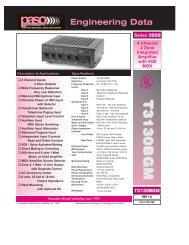
PROFESSIONAL AUDIO & SOUND®TMDIGITAL MUSIC AMPLIFIERSDIGITAL MUSIC SERIESDESCRIPTION AND APPLICATIONS❑ High Performance - High Reliability Design❑ Wide Frequency Response - Very Low Distortion❑ 7 Channel Inputs - 3 Zone Outputs❑ 5 Balanced Microphone Inputs❑ Phantom Power on all MIC Inputs❑ MIC 4/AUX 1 and MIC 5/AUX 2 InputsWith Stereo Summing❑ AUX1 and AUX2 Inputs Attenuator❑ 600 ohm Transformer BalancedTelephone Paging Input❑ MIX Buss and 600 ohm Line Output❑ Independent Input Controls❑ Rear Panel Port: Accepts Standard Module❑ Independent Module Level Control❑ AUX1 and Master Remote Volume Controls❑ External EQ Link❑ Tone by-pass and EQ Link switches❑ Pre-EQ Subwoofer Output❑ Post-EQ Subwoofer Output❑ Addressable Dual VOX BussVoice Activated Muting❑ VOX Variable Time Delay Function❑ Addressable Dual MUTE Buss❑ Direct Muting and Unmuting❑ 600 ohm and 8 ohm 1 WattMusic on Hold Amplifier❑ MOH Amplifier Source Selector❑ Zone 2 and 3, 1 Watt - 8 ohm Outputwith Separate Control❑ NO/NC VOX Operated Relay❑ 24 V DC 250 mA Regulated Power Supply Output❑ 8 ohm, 25 Volt & 70 Volt Output❑ Optional 19” Rack Mounting with Kit❑ Low profile - 2-Unit of Vertical Rack space❑ UL 6500 Listed (US - CANADA)UNPACKINGImmediately upon receipt of the amplifier, inspect the unitand shipping container for indications of improper handlingor in transit damage. The equipment was carefully inspectedand tested before leaving the factory. Notify theTransportation Company immediately if any damage isfound. ONLY THE CONSIGNEE CAN FILE A CLAIM WITHTHE CARRIER FOR DAMAGE DURING SHIPMENT. Besure to save the carton and packing material as evidence ofdamage for the shipper inspection. DO NOT SHIP the unitback to the factory unless authorized by the factory.IN TRANSIT DAMAGES ARE NOT COVERED BY THEPASO WARRANTY.Power Output:<strong>DMS3040</strong>DMS30<strong>80</strong>DMS3<strong>120</strong>Distortion:Frequency Response:Inputs:Input 1Input 2Input 3Input 4Input 5Input 6Input 7Sensitivity & Z:Input 1Input 2Input 3Input 4Input 5Input 6Input 7AUX 1 InputAttenuator:AUX 2 InputAttenuator:Phantom Power:Hum & Noise:Telephone Paging Input:Accessory Port:EQ LINK:Line Outputs:Inputs/Outputs:Subwoofer Outputs:Subwoofer Output Level:Music on Hold Output:Zone 2 Output:Zone 3 Output:Main Output Impedance:Controls:Front Panel:Rear Panel:Bass and Treble Controls:Tone By-Pass:Remote Volume Controls:MOH Source Selection:Zone 2/3 Source Selection:DUAL VOX:VOX BUSS 1:VOX BUSS 2:MUTE BUSS 1:MUTE BUSS 2:MUTE 2 DELAY:Unmuting:Power Supply Output:Auto VOX Relay:Rack Mounting:Internal Cooling Fan:Power Requirement:Power Consumption:AC Accessory Outlet:Terminations:Housing Finish:Output Power Indicator:Dimensions:Net Weight:<strong>DMS3040</strong>DMS30<strong>80</strong>DMS3<strong>120</strong>SPECIFICATIONS40 Watt RMS<strong>80</strong> Watt RMS<strong>120</strong> Watt RMSLess than 0.5% THD20 - 20,000 Hz ± 1 dbMicrophone 1 BalancedMicrophone 2 BalancedMicrophone 3 BalancedMicrophone 4 Balanced - AUX 1 (Stereo Summing)Microphone 5 Balanced - AUX 2 (Stereo Summing)Telephone Interface - Transformer BalancedModule PortMic 1 = 1.5 Mv - 250 ohmMic 2 = 1.5 Mv - 250 ohmMic 3 = 1.5 Mv - 250 ohmMic 4 = 1.5 Mv - 250 ohm - AUX 1 = 100 Mv - 47KohmMic 5 = 1.5 Mv - 250 ohm - AUX 2 = 100 Mv - 47KohmTel=100 Mv - 600 ohm - Transformer BalancedModule= 1 V - 47K ohmVariable (rear panel control)Variable (rear panel control)All Microphone Inputs by internal jumper (18 V)Mic -70 db, Aux -75 db600 ohm Transformer balancedAccepts Standard ModulePreamp out, Power Amp in with EQ Link SwitchLine Out 600 ohm - 1.5 V loadedMIX BUSSPre-EQ and Post-EQ Outputs1 Volt600 ohm-1 Volt Transformer Balanced1 Watt-8 ohm with Control1 Watt-8 ohm with Control8 ohm, 25 Volt and 70 Volt lineInput 1 Level, Input 2 Level, Input 3 Level, Input 4Level, Input 5 Level, Module Level, Bass and TreblePHONE Level - AUX 1 Attenuator - AUX 2 Attenuator- MOH/ZONE 1 Level Control - ZONE 2 Level Control- VOX 1/VOX 2 Sensitivity - MUTE 2 Delay± 10 dB at 100 Hz and 10 KHzOn - Off Switch (rear panel)AUX 1 Input Level and Master Volume (10 K)AUX 1 - AUX 2 - MODULE by internal jumperAUX 1 - AUX 2 - MODULE by internal jumperVoice Activated MutingAvailable on all 7 Inputs by internal jumpersAvailable on all 7 Inputs by internal jumpersAvailable on all 7 Inputs by internal jumpersAvailable on all 7 Inputs by internal jumpersAdjustable from 3 Sec to 30 Sec (rear panel control)MUTES/UNMUTES MIC 1 only24 V DC - 250 mA RegulatedNO/NC Contacts - VOX activated - Contacts Rating =30 VDC - 7 AOptional Model 27/3501 - 19” Rack Kit3” Thermally Controlled - Model DMS3<strong>120</strong> only117 Volt, 50-60 Hz<strong>DMS3040</strong> = AC = 630 VA - DMS30<strong>80</strong> = 750 VA -DMS3<strong>120</strong> = 850VA Max.500 W Max. UnswitchedScrew Terminals, RCA JacksBlackMulti-color LED (front panel)19” W., 12” D., 4” H. with feet (482X305X102 mm) 3.5”H (89 mm). less feet16 Lbs (8 Kg)19 Lbs (8.5 Kg)22 Lbs (11 Kg)PAGE 2 © copyright <strong>Paso</strong> <strong>Sound</strong> <strong>Products</strong>, Inc. 2002 Specifications are subject to change without notice <strong>DMS3040</strong>/30<strong>80</strong>/3<strong>120</strong>
TMPROFESSIONAL AUDIO & SOUNDPROFESSIONAL AUDIO & SOUND®TMDIGITAL MUSIC AMPLIFIERSDIGITAL MUSIC SERIESIMPORTANT SAFETY INSTRUCTIONSREAD BEFORE OPERATINGBEFORE OPERATING THE AMPLIFIER, BE SURE YOUFULLY UNDERSTAND ALL INSTRUCTIONS AND FEA-TURES OF THE UNIT.1) Read these instructions carefully.2) Keep these instructions.3) Heed all Warnings.4) Follow all instructions.5) DO NOT use this apparatus near water.6) Clean ONLY with a damp cloth.7) DO NOT block any of the ventilation openings.Install in accordance with the instructions provided.8) DO NOT install near any heat sources such asradiators, stoves, or other apparatus (including amplifiers)that produce heat.9) DO NOT mount amplifier into a container or aclosed unventilated closet while operating.10) DO NOT place any object or accessory equipmentsuch as Tuners, Mixers, Cassette Decks, etc. on top ofthe amplifier. Obstructing or closing the cabinet ventilationopenings may cause overheating.11) DO NOT defeat the safety purpose of the polarizedor grounding type plug. A polarized plug has twoblades with one wider than the other. A grounding typeplug has two blades and a third grounding prong. Thewide blade and or the third prong is provided for yoursafety. When the provided plug does not fit into yourREAD BEFORE OPERATINGoutlet, consult an electrician for replacement of theobsolete outlet.12) Use only the attachments and accessories specifiedin this manual.13) If a cart is used, use caution when moving thecart/apparatus combination to avoid injury from tipover.14) Unplug this apparatus during lighting storms orwhen unused for long periods of time.15) Refer all servicing to qualified service personnel.Servicing is required when the apparatus has beendamaged in any way, such as power supply cord orplug is damaged, liquid has been spilled or objectshave fallen into the apparatus, the apparatus has beenexposed to rain or moisture, does not operate normally,or has been dropped.16) DO NOT replace fuses unless power cord isremoved from the AC wall outlet.17) DO NOT install accessories unless the powercord is removed from the AC wall outlet.TO REDUCE THE RISK OF FIRE ORELECTRIC SHOCK DO NOT EXPOSETHIS APPLIANCE TO WATER, RAIN ORMOISTURERACK MOUNTINGA) Procure the optional accessory Rack Mount Kit Model 27/3501.B) Turn amplifier up side down and remove the four rubber feet by unscrewing the four holding screws.C) Remove two screws on each side of the amplifier holding the amplifier cover.D) Install the rack kit brackets by using the self-tapping screws provided.Fig. 3 - Rack Kit MountingDMSDIGITAL MUSIC SERIESDIGITAL MUSIC AMPLIFIEROUTPUT LEVELPEAKPOWER0 10 0 10 0 10 0 10 0 10 0 10-10 +10 -10 +10OINPUT 1 INPUT 2 INPUT 3 INPUT 4/AUX 1 INPUT 5/AUX 2 MODULEBASS TREBLE<strong>DMS3040</strong>/30<strong>80</strong>/3<strong>120</strong>SPECIFICATIONS ARE SUBJECT TO CHANGE WITHOUT NOTICEPAGE 3
PROFESSIONAL AUDIO & SOUND®TMDIGITAL MUSIC AMPLIFIERSDIGITAL MUSIC SERIESFig. 4 - FRONT PANEL CONTROLS10TMDMSDIGITAL MUSIC SERIESDIGITAL MUSIC AMPLIFIERPROFESSIONAL AUDIO & SOUNDOUTPUT LEVELPOWER0 10 0 10 0 10 0 10 0 10 0 10-10 +10 -10 +10OINPUT 1 INPUT 2 INPUT 3 INPUT 4/AUX 1 INPUT 5/AUX 2 MODULEBASS TREBLE1 2 3 4 5 6 7 8 91) INPUT 1 Volume Control6) Input Module Level Control2) INPUT 2 Volume Control7) BASS Control3) INPUT 3 Volume Control8) TREBLE Control4) INPUT 4/AUX 1 Volume Control9) On-Off Power Switch5) INPUT 5/AUX 2 Volume Control10) Output Level MeterPEAKPAGE 4 SPECIFICATIONS ARE SUBJECT TO CHANGE WITHOUT NOTICE <strong>DMS3040</strong>/30<strong>80</strong>/3<strong>120</strong>
PROFESSIONAL AUDIO & SOUNDCAUTION !®TMDIGITAL MUSIC AMPLIFIERSREMOVAL OF THE AMPLIFIER COVER PRESENTS AN ELECTRICAL SHOCK HAZARDALWAYS REMOVE THE POWER CORD FROM THE AC WALL OUTLETTHE FOLLOWING INSTRUCTIONS REQUIRE THE REMOVAL OF THE AMPLIFIER PROTECTIVE COVER AND AREPROVIDED FOR USE BY QUALIFIED PERSONNEL ONLY.TO AVOID THE RISK OF ELECTRICAL SHOCK DO NOT PERFORM ANY INSTALLATION OR SERVICING UNLESS YOUARE QUALIFIED TO DO SO. REFER INSTALLATION OR SERVICING TO QUALIFIED PERSONNEL.FUNCTION SWITCHES AND JUMPERS DEFAULT SETTING TABLEJUMPER AND JUMPER FUNCTION FACTORY FACTORYSWITCH ID NO. REFERENCE DESCRIPTION SETTING SETTINGMAIN PCB JUMPERSSW201 INPUT 1 - PHANTOM POWER ON - OFF OFFSW202 INPUT 2 - PHANTOM POWER ON - OFF OFFSW203 INPUT 3 - PHANTOM POWER ON - OFF OFFSW204 INPUT 4 - PHANTOM POWER ON - OFF OFFSW205 INPUT 1 (MIC 1) - UNMUTE ON - OFF OFFSW206 VOX RELAY - MUTE 1 - MUTE 2 M1SW207 INPUT 5 - PHANTOM POWER ON - OFF OFFSW210 INPUT 2 - VOX 1 - VOX 2 - OFF OFFSW211 INPUT 3 - VOX 1 - VOX 2 - OFF OFFSW212 INPUT 4 - VOX 1 - VOX 2 - OFF OFFSW213 INPUT 5 - VOX 1 - VOX 2 - OFF OFFSW214 TEL IN - VOX 1 - VOX 2 - OFF V1SW215 INPUT 1 - VOX 1 - VOX 2 - OFF V1SW216 TEL IN - MUTE 1 - MUTE 2 - OFF OFFSW217 INPUT 4/AUX 1 - MUTE 1 - MUTE 2 - OFF M1SW218 INPUT 3 - MUTE 1 - MUTE 2 - OFF OFFSW219 INPUT 2 - MUTE 1 - MUTE 2 - OFF OFFSW220 INPUT 1 - MUTE 1 - MUTE 2 - OFF OFFSW221 MODULE - VOX 1 - VOX 2 - OFF OFFSW222 MODULE - MUTE 1 - MUTE 2 - OFF OFFSW223 INPUT 5/AUX 2 - MUTE 1 - MUTE 2 - OFF M1SW227 CHIME TRIGGER - MUTE 1 - MUTE 2 M1SWITCHESSW208 INPUT 5 - MIC 5 OR AUX 2 SWITCH AUX 2SW209 MODULE IN SOURCE - AUX 1 OR AUX 2 SWITCH AUX 1SW228 INPUT 4 - MIC 4 OR AUX 1 SWITCH AUX 1SW229 INPUT 5 - MIC 5 OR AUX 2 SWITCH AUX 2MOH BOARD JUMPERSSW701 ZONE 2 INPUT SOURCE - AUX 1 - AUX 2 - MODULE AUX 1SW702 ZONE 1 INPUT SOURCE - AUX 1 - AUX 2 - MODULE AUX 1REAR PANEL SWITCHESSW301 TONE BYPASS Defeats Front Panel Bass & Treble SWITCH OFFSW302 EQ LINK Inserts External EQ between SWITCH OUTPreamp out and Power Amp InputDIGITAL MUSIC SERIES<strong>DMS3040</strong>/30<strong>80</strong>/3<strong>120</strong>SPECIFICATIONS ARE SUBJECT TO CHANGE WITHOUT NOTICEPAGE 7
PROFESSIONAL AUDIO & SOUND®TMDIGITAL MUSIC AMPLIFIERSDIGITAL MUSIC SERIESFUNCTION SWITCHES AND JUMPERSUNDERSTANDING THE INPUT FUNCTIONSDUAL VOX AND DUAL MUTE - The Amplifier provides two independentVOX (V1 & V2) and two MUTE (M1 & M2) SYSTEMSFUNCTION SOCKETS - EACH INPUT IS PROVIDED WITH AVOX (V1 & V2) AND A MUTE (M1 & M2) SOCKET.INPUTS VOX AND MUTE FUNCTION - All Inputs including theModule provide 2 - VOX SEND and 2 MUTE RECEIVE functions.The VOX and MUTE functions are SWITCHED-ON, on each Input,by Internal Jumpers provided for each Input. Two VOX BUSSSEND (V1 & V2) and two MUTE BUSS RECEIVE (M1 & M2) canbe independently or simultaneously SWITCHED-ON to suit theapplication requirement.SETTING THE VOX AND MUTE JUMPERSJUMPER SETTINGS - The VOX and MUTE Functions areSWITCHED-ON or OFF by setting the JUMPERS on the VOX (A)and MUTE (B) SOCKET. See Fig. 8A.The SOCKETS are located on the Main PCB inside the Amplifieras shown on the SWITCHES and JUMPERS LOCATION DIA-GRAM in this Manual. Each Socket is identified by an ID NUMBERand the FUNCTION and DEFAULT settings are listed on theFUNCTION SWITCHES and JUMPERS DEFAULT SETTINGTABLE in this Manual.TO SET: Lift the Jumper and reset as required. making sure thatthe JUMPER is properly positioned over the two shorting pins.VOX SENDSOURCE INANYINPUTV1V2AUDIO OUTTO VOX BUSS 1TO VOX BUSS 2The VOX JUMPER has three positions:The MUTE JUMPER has three positions:SOCKETID NO.OFFV 1VOX JUMPERSSOCKETSW215JUMPERMUTE JUMPERSSOCKETSW220OFF JUMPERM 1OFF, V1 and V2OFF, M1 and M2JUMPERMUTE RECEIVEDMS AnyinputM1M2FROM MUTE BUSS 1FROM MUTE BUSS 2Fig. 8 - Any Input VOX and MUTE FunctionsThe figure below shows how the VOX 1 Logic Switch and theMUTE 2 Logic Switch are SWITCHED-ON by moving the Jumpersfrom the OFF position to the V 1 and M 2 position. When the Inputis activated by a Source signal the corresponding VOX Signal issent to the V1 BUSS. When the VOX 2 is activated by another Inputthe MUTE Signal is present on the MUTE 2 BUSS and it willMUTE this InputVOX SENDSOURCE INMUTE RECEIVEANYINPUTDMS Anyinput 02V1V2M1 OFFXM2OFFJUMPERAUDIO OUTXSW215 VOX 2 BUSS OFFSW220JUMPERVOX 2 BUSS ONJUMPERMUTE 1 BUSS OFFMUTE 2 BUSS ONFig. 8B - Any Input VOX 1 and MUTE 2 ActivatedV 2Vox Mute SocketAM 2BFig. 8A - VOX and MUTE SocketsSETTING MORE THAN ONE FUNCTIONMore than one JUMPER may be used on a VOX SOCKET asshown below. In this example both the VOX 1 and VOX 2 functionsare SWITCHED -ON when the Input is activated. For this purposeadditional JUMPERS are packed with each Amplifier.OFFVOX 1 BUSS ONV 1 JUMPERVOX SOCKETV 2 JUMPERVox Socket 01VOX 2 BUSS ONAMore than one JUMPER may be used on a MUTE SOCKET asshown below. In this example both the MUTE 1 and MUTE 2 functionswill MUTE this INPUT when either VOX 1 or VOX 2 are activatedby other INPUTS.OFFM 1MUTE SOCKETM 2Mute Socket 01JUMPERJUMPERBMUTE 1 BUSS ONMUTE 2 BUSS ONNOTE: BE SURE NOT TO SET BOTH THE VOX AND CORRE-SPONDING MUTE ON THE SAME INPUT OR THE INPUT WILLMUTE ITSELF WHEN ACTIVATED.EXAMPLE: INPUT 1 - V 1 and M 1 BOTH ON.PAGE 8 SPECIFICATIONS ARE SUBJECT TO CHANGE WITHOUT NOTICE <strong>DMS3040</strong>/30<strong>80</strong>/3<strong>120</strong>
PROFESSIONAL AUDIO & SOUND®TMDIGITAL MUSIC AMPLIFIERSDIGITAL MUSIC SERIESFUNCTION SETTINGS EXAMPLESVOX SENDMIC INVOX SENDMUSICINMUTE RECEIVEINPUT 1INPUT 4AUX 1Input 1-4 - V1 - 01V1V2V1V2OFF VOX 1 BUSS ONJUMPERMIC OUTXSW215 VOX 2 BUSS OFFWHEN MIC 1 ISACTIVATED THE VOX 1BUSS IS SWITCHED-ONSW220AND THE SIGNALOFF JUMPERPRESENT ON THEMUTE 1 BUSS OFFM1MUTE 1 BUSS WILLXMUTE INPUT 4/AUX 1XM2MUTE 2 BUSS OFFMUTE RECEIVEWHEN MIC 1 IS ACTIVATEDTHE VOX 1 BUSS ISSWITCHED-ON AND THESIGNAL PRESENT ON THEMUTE 1 BUSS WILL MUTE THEMUSIC FROM INPUT 4/AUX 1MIC INWHEN MIC 1 ISACTIVATED THE VOX 1BUSS AND THE VOX 2BUSS ARE SWITCHED-ON AND THE SIGNALSPRESENT ON THE MUTE1 & 2 BUSS WILL MUTETHE INPUT 4/AUX 1 ANDINPUT 5/AUX 2JUKEBOXINWHEN INPUT 4AUX 1 ISACTIVATED THE VOX 2BUSS IS SWITCHED-ONAND THE SIGNAL PRESENTON THE MUTE 2 BUSS WILLMUTE THE MUSIC FROMINPUT 5/AUX 2MUTE-2DELAY3 to 30 Sec31MUSICININPUT 5/AUX 2 ISMUTED BY BOTH INPUT4/AUX 1 AND INPUT 1WHEN ACTIVATED.EXAMPLE 9VOX - MUTE JUMPERS SETTINGOFF JUMPERVOX 1 BUSS OFFXXSW212 VOX 2 BUSS OFFMUSIC OUTM1 OFF MUTE 1 BUSS ONJUMPERXM2SW217EXAMPLE 9BJUMPERMUTE 2 BUSS OFFVOX - MUTE JUMPERS SETTINGINPUT 1INPUT 4AUX 1INPUT 5AUX 2V1V2V1V2V1V2M2Input 1-4 -5 - 03OFF VOX 1 BUSS ONJUMPERMIC OUTSW215SW220OFF JUMPERMUTE 1 BUSS OFFM1XXM2MUTE 2 BUSS OFFOFFVOX 1 BUSS OFFXJUMPERSW212 VOX 2 BUSS ONJUKEBOX OUTSW217OFFMUTE 1 BUSS ONM1 JUMPERXM2 XOFF JUMPER VOX 1 BUSS OFFXXVOX 2 BUSS OFFSW213MUSIC OUTSW223M1OFF MUTE 1 BUSS ONJUMPERJUMPERXVOX 2 BUSS OFFJUMPERMUTE 2 BUSS OFFMUTE 2 BUSS ONVOX 1 BUSS MUTE 1 BUSSVOX 2 BUSS MUTE 2 BUSSVOX 1 BUSS MUTE 1 BUSSVOX 2 BUSS MUTE 2 BUSSVOX SENDMIC INWHEN MIC1 ISACTIVATED THE VOX 1BUSS AND THE VOX 2BUSS ARE SWITCHED-ON AND THE SIGNALSPRESENT ON THEMUTE 1 & 2 BUSS WILLMUTE THE TEL INPUTAND INPUT 4/AUX 1VOX SENDTEL INWHEN THE TELINPUT IS ACTIVATEDTHE VOX 1 BUSS ISSWITCHED-ON ANDTHE SIGNALPRESENT ON THEMUTE 1 BUSS WILLMUTE INPUT 4/AUX 1VOX SENDMUSICINWHEN MIC1 OR TEL AREACTIVATED THE VOX 1BUSS IS SWITCHED-ONAND THE SIGNAL PRESENTON THE MUTE 1 BUSS WILLMUTE THE MUSIC FROMINPUT 4/AUX 1MUTE RECEIVEINPUT 1INPUT 4AUX 1Input 1-4 -Tel - 01V1V2MUTE RECEIVETEL INPUTMUTE RECEIVEEXAMPLE 9AVOX - MUTE JUMPERS SETTINGV1V2V1V2OFF JUMPERVOX 1 BUSS OFFXXSW212 VOX 2 BUSS OFFMUSIC OUTM1 OFFM2OFFMIC OUTOFF JUMPERM1XM2XM2OFFOFFM1XXJUMPERJUMPERSW215 VOX 2 BUSS ONSW220JUMPERPHONE OUTSW217VOX 1 BUSS ONMUTE 1 BUSS OFFMUTE 2 BUSS OFFXSW214 VOX 2 BUSS OFFSW216JUMPERJUMPEREXAMPLESJUMPERVOX 1 BUSS ONMUTE 1 BUSS OFFMUTE 2 BUSS ONMUTE 1 BUSS ONMUTE 2 BUSS OFFVOX 1 BUSS MUTE 1 BUSSVOX 2 BUSS MUTE 2 BUSSEXAMPLE 9 - INPUT 1 (MIC 1) mutes INPUT 4/AUX 1. When theMicrophone is activated the Music on AUX 1 is muted.EXAMPLE 9A - INPUT 1 (MIC 1) and TEL IN (Phone Paging) bothmute INPUT 4/AUX 1. When the Microphone or the Phone Pagingare activated the Music on AUX 1 is muted. The Microphone has priorityover the Phone Paging. When MIC 1 is activated both the PhonePaging and the Music on AUX 1 are muted.EXAMPLE 9B - INPUT 1 (MIC 1) mutes INPUT 4/AUX 1 and INPUT5/AUX 2. INPUT 4 (Jukebox) mutes INPUT 5 (Sat. Rcvr). When theJukebox is turned-On the Background Music on AUX 2 is muted.MUTE 2 DELAY (Reference 31) Control is provided. The MicrophonePaging has priority over the Background Music and the Jukebox.<strong>DMS3040</strong>/30<strong>80</strong>/3<strong>120</strong>SPECIFICATIONS ARE SUBJECT TO CHANGE WITHOUT NOTICEPAGE 9
PROFESSIONAL AUDIO & SOUND®TMDIGITAL MUSIC AMPLIFIERSDIGITAL MUSIC SERIESINPUT 1 SETTING AS A MICROPHONE INPUTMICROPHONE TYPEThe Microphone Input accepts Low Impedance (250-600 ohm)Dynamic Microphones. The Microphone may be a balanced outputtype (three wire) or an unbalanced output type (two wire).INSTALLATION AND WIRINGCAUTION: TO PREVENT POSSIBLE DAMAGE TO SPEAKERS OR THE AMPLIFIERALL INPUT CONNECTIONS MUST BE MADE WITH THE AMPLIFIER POWER OFF.PASO MICROPHONESAll PASO low impedance Microphones have a balanced output forbest performance. Connect the RED lead to terminal HOT, theWHITE lead to terminal COM and the SHIELD to terminal G.INPUT 1THREE LEADS BALANCED MICROPHONE WIRINGVOX - MUTE JUMPERS SETTINGVOX SENDMIC INInput 1 - V1 - 01MUTE RECEIVEV1V2OFFAUDIO OUTM1 OFFXXM2SW215JUMPERJUMPERSW220JUMPERVOX 1 BUSSACTIVATEDXVOX 2 BUSS OFF= JUMPERMUTE 1 BUSS OFFMUTE 2 BUSS OFFThe microphone leads color refers to <strong>Paso</strong> Microphones only.When using other brand refer to instructions packed with thatunit.SHIELDMICWHITELo ZREDVOX SENDMICLo ZMIC INInput 1 - V1 - 01MUTE RECEIVEINPUT 1INPUT 1 - Default Jumper SettingsThe Diagram at Left shows theDefault Settings for INPUT 1.VOX 1 is SWITCHED ONVOX 2 is SWITCHED OFFMUTE 1 is SWITCHED OFFMUTE 2 is SWITCHED OFFWhen the INPUT 1 (MIC 1) isactivated the VOX 1 BUSS is ONand it will MUTE any Input with theMUTE 1 Setting SWITCHED ON.INPUT 1 (MIC)G COM HOT250ohm 1.5mVBALANCEDINPUT 2 (MIC)G COM HOTFig. 10 - Balanced Microphone Input 1 WiringTWO LEADS UNBALANCED MICROPHONE WIRINGVOX - MUTE JUMPERS SETTINGV1V2OFFSW215JUMPERJUMPERAUDIO OUTSHIELDVOX 1 BUSSACTIVATEDXVOX 2 BUSS OFF= JUMPERSW220M1 OFF JUMPERMUTE 1 BUSS OFFXXM2MUTE 2 BUSS OFFHOT LEADINPUT 3 (MIC)G COM HOTNOTE: To change theINPUT Default Settingsrefer to the appropriatesection in this Manual3<strong>120</strong> Micbal 01INPUT 1 - Default Jumper SettingsThe Diagram at Left shows theDefault Settings for INPUT 1.VOX 1 is SWITCHED ONVOX 2 is SWITCHED OFFMUTE 1 is SWITCHED OFFMUTE 2 is SWITCHED OFFWhen the INPUT 1 (MIC 1) isactivated the VOX 1 BUSS is ONand it will MUTE any Input with theMUTE 1 Setting SWITCHED ON.INPUT 1 (MIC)G COM HOT250ohm 1.5mVBALANCEDINPUT 2 (MIC)G COM HOTFig. 10A - Unbalanced Microphone Input 1 WiringINPUT 3 (MIC)G COM HOTNOTE: To change theINPUT Default Settingsrefer to the appropriatesection in this Manual3<strong>120</strong> Micunbal 01WIRINGMICROPHONE INPUTAttach the microphone leads to the terminalstrip as per diagrams at left.DO NOT GROUND THE MICROPHONECABLE SHIELD TO THE CHASSIS OFTHE AMPLIFIERBALANCED MICROPHONEIMPORTANT NOTE: The use of anunbalanced Microphone (two leads) isnot recommended. For best results in aPA Application always use aUnidirectional Dynamic, LowImpedance, Balanced Microphone(three leads).UNBALANCED MICROPHONEAttach the Microphone leads to the terminalstrip as per diagram in Fig 8A. Thecable length should not exceed: 15 Ft.(4.5 m).CABLECABLE LENGTH - If the distancebetween the Microphone and theAmplifier Input is greater than 15 ft (4.5m) a Balanced Microphone must beused. Use a two conductor shielded wireand connect Microphone to Amplifier asper Diagram in Fig. 10.MICROPHONE CABLE ROUTING - TheMicrophone Cable should be carefullyrouted. Improper Cable routing willcause spurious oscillations, regenerativenoises, hum, etc. that may permanentlydamage the Amplifier.• Do not route cable next to powerlines.• Do not route cable near or overFluorescent Fixtures.• Do not route cable next toSpeaker Wires.• Do not install cable inside PowerLine Conduits.• Avoid the use of staples that maypenetrate the cable.PAGE 10 SPECIFICATIONS ARE SUBJECT TO CHANGE WITHOUT NOTICE <strong>DMS3040</strong>/30<strong>80</strong>/3<strong>120</strong>
PROFESSIONAL AUDIO & SOUND®TMDIGITAL MUSIC AMPLIFIERSDIGITAL MUSIC SERIESINPUT 1 - USING A DESK BASE MICROPHONEINSTALLATION AND WIRINGUSING A PUSH-TO-TALK DESK BASE MICROPHONEMicrophone paging and precedence over AUX 1 or AUX 2 channelsmay be accomplished by using a Desk Base or a GooseneckMicrophone. Wire the Microphone output leads to the MIC input terminalsas per Fig. 11A.MUTING: The Amplifier is equipped with two independent MutingCircuits:• Direct Muting by shorting the MUTE Terminals• Automatic Muting with VOX - Voice Activated MutingFor additional information on the Muting operation referto the Muting Functions section of this Manual.CAUTION: TO PREVENT POSSIBLE DAMAGE TO SPEAKERSOR THE AMPLIFIER ALL INPUT CONNECTIONS MUST BEMADE WITH THE AMPLIFIER POWER OFF.WIRINGWire the Desk Base Microphone leads to the MicrophoneInput terminal strip as per diagram in Fig 11A. CheckMicrophone instructions and connect HOT LEAD (B) toTerminal HOT, COMMON LEAD (A) to Terminal COM andSHIELD LEAD to Terminal G. Connect Muting Switch toTerminals MUTE 1 or MUTE 2 and G as shown.DO NOT GROUND THE MICROPHONE CABLE SHIELDTO THE CHASSIS OF THE AMPLIFIERb50sidePush to Talk KeyFig. 11 - Desk Base MicrophoneMUTING - PRIORITY SETTINGSDirect Muting is provided by the Desk Base Muting Switch wired asper diagram in Fig. 11A. If Auto-Mute (VOX) is desired follow instructionsbelow. The Desk Base Muting Switch can be omitted.MUTING INPUT 4/AUX 1 (MUSIC INPUT)To mute Input 4/AUX 1 (Music Input) when Paging from MIC 1, set INPUT4/AUX 1 MUTE 1 JUMPER to ON Position. Each time MIC 1 is activatedthe Program on Input 4/AUX 1 is automatically muted by the VOX.DESK BASE/GOOSENECK MICROPHONE WITH MUTING SWITCHVOX - MUTE JUMPERS SETTINGVOX SENDPush to Talk KeyMIC ININPUT 1V1V2OFFSW215JUMPERAUDIO OUTVOX 1 BUSSACTIVATEDXVOX 2 BUSS OFF= JUMPERMASTERREMOTEVOLUMEG M2 M1 RVC RVCGROUNDMUTE 2MUTE 1INPUT 1 - Default Jumper SettingsThe Diagram at Left shows theDefault Settings for INPUT 1.VOX 1 is SWITCHED ONVOX 2 is SWITCHED OFFMUTE 1 is SWITCHED OFFMUTE 2 is SWITCHED OFFWhen the INPUT 1 (MIC 1) isactivated the VOX 1 BUSS is ONand it will MUTE any Input with theMUTE 1 Setting SWITCHED ON.MUTE RECEIVEM1 OFFXXM2SW220JUMPERMUTE 1 BUSS OFFMUTE 2 BUSS OFFINPUT 1 (MIC)G COM HOT250ohm 1.5mVBALANCEDINPUT 2 (MIC)G COM HOTINPUT 3 (MIC)G COM HOTConnect Desk Base or GooseneckMicrophone as per diagram below.Connect Muting Switch to MUTE 1or MUTE 2 and G Terminals.If using the VOX system themuting switch is unnecessary.MICLo ZMUTING SWITCHSHIELDABNOTE: To change theINPUT Default Settingsrefer to the appropriatesection in this Manual3<strong>120</strong> Micbase 01<strong>DMS3040</strong>/30<strong>80</strong>/3<strong>120</strong>Fig. 11A - Input 1 and Muting TerminalsSPECIFICATIONS ARE SUBJECT TO CHANGE WITHOUT NOTICEPAGE 11
PROFESSIONAL AUDIO & SOUNDCAUTION ! REMOVAL OF THE AMPLIFIER COVER PRESENTS AN ELECTRICAL SHOCK HAZARDALWAYS REMOVE THE POWER CORD FROM THE AC WALL OUTLETTHE FOLLOWING INSTRUCTIONS REQUIRE THE REMOVAL OF THE AMPLIFIER PROTECTIVE COVER AND AREPROVIDED FOR USE BY QUALIFIED PERSONNEL ONLY.TO AVOID THE RISK OF ELECTRICAL SHOCK DO NOT PERFORM ANY INSTALLATION OR SERVICING UNLESS YOUARE QUALIFIED TO DO SO. REFER INSTALLATION OR SERVICING TO QUALIFIED PERSONNEL.INPUT CONNECTIONS®TMDIGITAL MUSIC AMPLIFIERSDIGITAL MUSIC SERIESCONDENSER AND ELECTRET MICROPHONESCONDENSER AND ELECTRET TYPE MICROPHONESCondenser and Electret Microphones require a DC OperatingVoltage. The Amplifier provides this operating voltage or PhantomPower selectively on Inputs.1-2-3-4-5.Prior to selecting the Condenser or Electret Microphone be surethat the Operating Voltage and Output Impedance of the devicematch the Input characteristics of the Amplifier listed below.Phantom PowerInput Impedance= 18 Volt DC= 250 to 600 ohmACCESS TO PHANTOM POWER SELECTORS1) Remove Power Cord from AC Outlet.2) Remove the three screws on each side of the Amplifier.3) Lift Cover and carefully slide Cover out towards the rear.4) Jumpers are located on the Main Printed Circuit Board.CONFIGURATION TABLESPHANTOM POWER SELECTORSPHANTOM POWER SELECTOR JUMPERBy following the Main Printed Board Layout locate the SelectorJumpers with the ID No. as indicated on the Table below.Reset the Phantom Power Jumpers for INPUT 1 - 2 or 3 to the ONposition as desired. Lift the Mini Jumper out of the socket pins andre-position to the ON position. Make sure the Jumper is lined upwith the socket pins.INPUT 4 and 5 CONFIGURED AS MIC INPUTSIf INPUT 4 and INPUT5 need to be configured as MicrophoneInputs, reset the Phantom Power Jumpers as well as theSwitches provided for the two Inputs as indicated in the Tablebelow.WIRINGCONDENSER/ELECTRET MICROPHONECarefully follow the wiring instruction packed with the Microphoneused. Attach the microphone leads to the terminal strip as per diagramper Fig. below.DO NOT GROUND THE MICROPHONE CABLE SHIELD TO THECHASSIS OF THE AMPLIFIERBALANCED CONDENSER/ELECTRET MICROPHONE WIRINGMIC INPUTS PHANTOM POWER JUMPER SETTINGWHEN USING ELECTRET MICROPHONESINPUT 1 On JUMPER OFFSW201INPUT 2 On JUMPER OFFSW202INPUT 3 On JUMPER OFFSW203INPUT 4 On JUMPER OFF (When set as MIC 4)SW204INPUT 5 On JUMPER OFF (When set as MIC 5)SW207MICLo ZSHIELDINPUT 4 - 5 SWITCH SETTINGS WHENCONFIGURING AS MICROPHONE INPUTINPUT 1 (MIC)G COM HOTHOT LEADHOT LEADInput Switch No. SettingINPUT 4 SW228 MIC 4INPUT 5 SW208 MIC 5INPUT 5 SW229 MIC 5-0 +18V +18V250ohm 1.5mVBALANCEDINPUT 2 (MIC)G COM HOTINPUT 3 (MIC)G COM HOTInputINPUT 4 - 5 DEFAULTSWITCH SETTINGSSwitch No. SettingINPUT 4 SW228 AUX 1INPUT 5 SW208 AUX 2INPUT 5 SW229 AUX 2INPUT 1- 2 - 3 - 4 - 5 DEFAULTJUMPER SETTINGSInput Jumper No. SettingINPUT 1 SW201 OFFINPUT 2 SW202 OFFINPUT 3 SW203 OFFINPUT 4 SW204 OFFINPUT 5 SW207 OFF3<strong>120</strong> Micbal ElectretFig. 12 - Balanced Condenser/Electret Microphone Wiring - Configuration TablesPAGE 12 SPECIFICATIONS ARE SUBJECT TO CHANGE WITHOUT NOTICE <strong>DMS3040</strong>/30<strong>80</strong>/3<strong>120</strong>
DIGITAL MUSIC SERIESTMDIGITAL MUSIC AMPLIFIER0 10 0 10 0 10 0 10 0 10 0 10-10 +10 -10 +10INPUT 1 INPUT 2 INPUT 3 INPUT 4/AUX 1 INPUT 5/AUX 2 MODULEBASS TREBLEPROFESSIONAL AUDIO & SOUNDOUTPUT LEVELPEAKPOWEROPROFESSIONAL AUDIO & SOUND®TMDIGITAL MUSIC AMPLIFIERSDIGITAL MUSIC SERIESINSTALLATION AND WIRINGPAGING FROM THE TELEPHONE SYSTEMCAUTION: TO PREVENT POSSIBLE DAMAGE TO SPEAKERS OR THE AMPLIFIER ALL INPUT CONNECTIONS MUST BE MADEWITH THE AMPLIFIER OFF (POWER OFF).DMSTELDMS AmplifierKSUKey Service UnitTelephonetelpaginFig. 13 - Connecting to the Telephone Paging KSUWIRING - The Amplifier is interface ready for the Telephoneline in applications requiring paging from the telephone system.The Telephone line Paging Output (Tip and Ring) canbe directly connected to the TEL input and to the HOT andCOM as shown in the wiring diagram Fig. 12A.CABLE - Use a two conductor twisted wire.NOTE: The Telephone Paging Input is a TransformerBalanced 600 ohm input.DO NOT GROUND THE TIP OR RING WIRE TO THECHASSIS OF THE AMPLIFIEROUTPUT LEVEL CONTROL - Use TEL OUTPUT LEVELControl located on the Rear panel. After wiring adjust controlfor the desired output level.VOICE ACTIVATED MUTING (VOX) - Muting of the AUX 1channel (music muting) during Paging is automatic via theVoice Activated Muting System. No contact closure for theMuting Circuit is required from the Telephone system. Foradditional information on the Muting operation refer to theMuting Functions section of this Manual.PHONE PAGING PRIORITY OVER MICROPHONES -Priority over any Microphone Input may be accomplished bysetting the MIC Inputs MUTE Jumpers.TELEPHONE SYSTEM PAGING WIRINGBALANCED TELEPHONE PAGING WIRINGVOX SENDTEL INVOX - MUTE JUMPERS SETTINGTEL INPUTV1V2OFFSW214JUMPERJUMPERPAGING OUTVOX 1 BUSSACTIVATEDXVOX 2 BUSS OFF= JUMPERTEL INPUT - Default Jumper SettingsThe Diagram at Left shows theDefault Settings for TEL INPUT.VOX 1 is SWITCHED ONVOX 2 is SWITCHED OFFMUTE 1 is SWITCHED OFFMUTE 2 is SWITCHED OFFWhen the TEL INPUT (PHONE) isactivated the VOX 1 BUSS is ONand it will MUTE any Input with theMUTE 1 Setting SWITCHED ON.MUTE RECEIVESW216M1 OFF JUMPERMUTE 1 BUSS OFFXM2XMUTE 2 BUSS OFFTelephone SystemPaging OutputRINGTIPTELG COM HOT600 ohm 100 mVBALANCEDNOTE: To change theINPUT Default Settingsrefer to the appropriatesection in this Manual3<strong>120</strong> Telpaging 01Fig. 13A - Balanced Telephone Input Wiring<strong>DMS3040</strong>/30<strong>80</strong>/3<strong>120</strong>SPECIFICATIONS ARE SUBJECT TO CHANGE WITHOUT NOTICEPAGE 13
PROFESSIONAL AUDIO & SOUND®TMDIGITAL MUSIC AMPLIFIERSDIGITAL MUSIC SERIESINSTALLATION AND WIRINGAUX 1ATTENUATOR3<strong>120</strong> Aux1 01DEFAULT JUMPERS AND SWITCH SETTINGSW212 = OFFSW217 = M 1SW228 = AUX 1MUSICINAUX 1 - MIC 4 SWITCHSW228AUX 1 MIC 418 19LSETTING INPUT 4 AS AUX 1INPUT - 4 (AUX1)47 kohm 100 mVRINPUT 4AUX 1Input 1-4 - V1 - 01INPUT-5(AUX2)47kohm 100mVL(AUX2)ATTENUATORRV1V2M2INPUT 5MIC-AUX2BY INTERNALSWITCHMUSIC OUTPUTOFF JUMPERVOX 1 BUSS OFFXXVOX 2 BUSS OFFSW212MUSIC OUTM1 OFFXSW217JUMPERRWHEN MIC 1 ISACTIVATED THE VOX 1BUSS IS SWITCHED-ONAND THE SIGNALPRESENT ON THEMUTE 1 BUSS WILLMUTE THE MUSICFROM INPUT 4/AUX 1SATELLITE RECEIVERCDMUTE 1 BUSS ONMUTE 2 BUSS OFFAM/FM TUNERCD PLAYERTAPE DECKFig. 14 - Rear Panel AUX 1 Input DiagramINPUT - 4 (AUX1)47 kohm 100 mVAUX 1LATTENUATOR3<strong>120</strong> Stereo Summ18 19Fig. 14A - Stereo Summing and AUX 1 Input AttenuatorRLpasoTRACK 01INPUT 4/AUX 1 DEFAULT SETTINGJUMPERS/SWITCH NO. FACTORY SETTINGSW212 - VOX JUMPER= OFFSW217 - MUTE JUMPER = M 1SW228 - AUX1-MIC4 SWITCH = AUX 1AUX 1INPUT 4 SET AS AUX 1 (Reference. 19)The AUX 1 input is provided for high level program source.The output from a Satellite Receiver, Tuner, Tape CassetteDeck, CD Player or other high level program source maybe directly connected to this input.AUX 1 SENSITIVITY ATTENUATOR (Reference. 18)The AUX 1 Input is equipped with a Sensitivity Attenuatorthat allows the interface of the Input with Devices having awide range of Output Levels.TYPICAL OUTPUT LEVEL OF MUSIC DEVICES:Satellite Receivers = 1 to 5 VoltDigital Tuners/Receivers = 100 to 300 MvCD Players/Changers = 2 to 3 VoltTape Decks= 500 to 700 MvBy adjusting the Input Sensitivity to the level that matchesthe device used the correct interface with the Amplifier isachieved resulting in lower overall distortion and better frequencyresponse characteristics.SETTING THE AUX 1 INPUT ATTENUATORConnect a Music Source to the Amplifier.Turn Attenuator (rear panel) fully counterclockwise.Turn INPUT 4 Front Panel Control to midway.Switch Amplifier and Music Source ON.Turn Attenuator Control (rear panel) until desired OutputLevel is achieved.Adjust INPUT 4 Front Panel Level Control Up-Down asdesired.STEREO SUMMINGMost Music Source Devices provide a Stereo Output.Accordingly the Amplifier is equipped with two Jacks for theAUX 1 Input (L and R). The two Inputs are internallybuffered and electronically mixed to Mono. This systemensures that the Music Device is properly loaded and thatthe Stereo Signals are correctly summed (L+R) to Monowithout distortion.CABLETo connect the music source devices to the AUX 1 Inputuse two single conductor shielded audio cable terminatedin a single prong phono plug on both ends.AUX 1 INPUT MUTINGMUTING - WHEN MIC 1 OR THE TEL IN ARE ACTI-VATED THE VOX 1 BUSS IS SWITCHED-ON ANDTHE SIGNAL PRESENT ON THE MUTE 1 BUSSWILL MUTE THE MUSIC FROM AUX 1.PAGE 14 SPECIFICATIONS ARE SUBJECT TO CHANGE WITHOUT NOTICE <strong>DMS3040</strong>/30<strong>80</strong>/3<strong>120</strong>
PROFESSIONAL AUDIO & SOUND®TMDIGITAL MUSIC AMPLIFIERSDIGITAL MUSIC SERIESINSTALLATION AND WIRINGAUX 1ATTENUATOR3<strong>120</strong> Aux2 01DEFAULT JUMPERS AND SWITCH SETTINGSW213 = OFFSW223 = M 1SW208 = AUX 2SW229 = AUX 2INPUT - 4 (AUX1)47 kohm 100 mVMUSICINAUX 2 - MIC 5 SWITCHSW208 and SW229AUX 2 MIC 5SET TO AUX 2LSETTING INPUT 5 AS AUX 220RRINPUT 5AUX 2Input 1-4 - V1 - 0121V1V2M2INPUT 5MIC-AUX2BY INTERNALSWITCHMUSIC OUTPUTOFF JUMPERVOX 1 BUSS OFFXXVOX 2 BUSS OFFSW213MUSIC OUTM1 OFFINPUT 5 (AUX 2)47 Kohm 100 mVL (AUX 2)ATTENUATORXSW223JUMPERRWHEN MIC 1 ISACTIVATED THE VOX 1BUSS IS SWITCHED-ONAND THE SIGNALPRESENT ON THEMUTE 1 BUSS WILLMUTE THE MUSICFROM INPUT 5/AUX 2MUTE 1 BUSS ONMUTE 2 BUSS OFFSATELLITE RECEIVERCDAM/FM TUNERCD PLAYERTAPE DECKFig. 15 - Rear Panel AUX 2 Input Diagram20R213<strong>120</strong> Stereo Summ 01INPUT 5 (AUX 2)47 Kohm 100 mVL (AUX 2)ATTENUATORINPUT 5MIC-AUX2Fig. 15A - Stereo Summing and AUX 2 Input AttenuatorLpasoTRACK 01INPUT 5/AUX 2 DEFAULT SETTINGJUMPERS/SWITCH NO. FACTORY SETTINGSW213 - VOX JUMPER= OFFSW223 - MUTE JUMPER = M 1SW208 - AUX 2-MIC 5 SWITCH = AUX 2SW229 - AUX 2-MIC 5 SWITCH = AUX 2AUX 2INPUT 5 SET AS AUX 2 (Reference. 20)The AUX 2 input is provided for high level program source.The output from a Jukebox, Tuner, Tape Cassette Deck,CD Player or other high level program source may bedirectly connected to this input.AUX 2 SENSITIVITY ATTENUATOR (Reference. 21)The AUX 2 Input is equipped with a Sensitivity Attenuatorthat allows the interface of the Input with Devices having awide range of Output Levels.TYPICAL OUTPUT LEVEL OF MUSIC DEVICES:Satellite Receivers = 1 to 5 VoltDigital Tuners/Receivers = 100 to 300 MvCD Players/Changers = 2 to 3 VoltTape Decks= 500 to 700 MvBy adjusting the Input Sensitivity to the level that matchesthe device used the correct interface with the Amplifier isachieved resulting in lower overall distortion and better frequencyresponse characteristics.SETTING THE AUX 2 INPUT ATTENUATORConnect a Music Source to the Amplifier.Turn Attenuator (rear panel) fully counterclockwise.Turn INPUT 5 Front Panel Control to midway.Switch Amplifier and Music Source ON.Turn Attenuator Control (rear panel) until desired OutputLevel is achieved.Adjust INPUT 5 Front Panel Level Control Up-Down asdesired.STEREO SUMMINGMost Music Source Devices provide a Stereo Output.Accordingly the Amplifier is equipped with two Jacks for theAUX 1 Input (L and R). The two Inputs are internallybuffered and electronically mixed to Mono. This systemensures that the Music Device is properly loaded and thatthe Stereo Signals are correctly summed (L+R) to Monowithout distortion.CABLETo connect the music source devices to the AUX 1 Inputuse two single conductor shielded audio cable terminatedin a single prong phono plug on both ends.AUX 2 INPUT MUTINGMUTING - WHEN MIC 1 OR THE TEL IN ARE ACTI-VATED THE VOX 1 BUSS IS SWITCHED-ON ANDTHE SIGNAL PRESENT ON THE MUTE 1 BUSSWILL MUTE THE MUSIC FROM AUX 2.<strong>DMS3040</strong>/30<strong>80</strong>/3<strong>120</strong>SPECIFICATIONS ARE SUBJECT TO CHANGE WITHOUT NOTICEPAGE 15
PROFESSIONAL AUDIO & SOUND®TMDIGITAL MUSIC AMPLIFIERSDIGITAL MUSIC SERIESADDRESSABLE DUAL VOX SYSTEMINSTALLATION AND WIRINGVOX - VOICE ACTIVATED MUTINGDUAL VOX - VOICE ACTIVATED MUTING - The Amplifieris equipped with a DUAL noiseless, fast acting Logic VOXSwitching System. When any of the INPUTS are activatedand a Signal is present on a given INPUT and either VOX 1or VOX 2 or BOTH are Switched-ON (using internalJumpers) then the MUTE 1 or MUTE 2 BUSS or BOTH areACTIVE. If any of the INPUTS have the MUTE 1 or MUTE2 Switched-ON (by Internal Jumpers) then the INPUT (orINPUTS) will be MUTED according to the Jumpers Setting.Once the SIGNAL-ON on the ACTIVE INPUT is terminatedthe normal functions are automatically restored on all mutedinputs.ACCESS TO VOX AND MUTE JUMPERSREFER TO JUMPERS AND SWITCHES INTERNALACCESS.CAUTION: PRIOR TO PERFORMING THE ABOVE OPER-ATION BE SURE TO FOLLOW THE SAFETY NOTESREFERRING TO THE REMOVAL OF THE AMPLIFIERCOVER.VOX SENSITIVITY CONTROLSVOX 1 AND VOX 2 SENSITIVITY CONTROLSThe VOX 1 and VOX 2 Sensitivity Controls set the sensitivitylevel at which point the VOX 1 and VOX 2 are respectivelyengaged during INPUT ACTIVATION. The VOX SensitivityControls are located on the Amplifier Rear Panel.VOX 1 SENSITIVITY CONTROL = Reference 33VOX 2 SENSITIVITY CONTROL = Reference 32VOX SENSITIVITY CONTROLSVOX-1 VOX-2 MUTE-2SENS SENS DELAY33DMS3<strong>120</strong> Vox Sens 013231Fig. 16 - Rear Panel VOX 1 and VOX 2 Sensitivity Controland MUTE 2 Delay ControlVOX SENSITIVITY ADJUSTMENTVOX SENSITIVITY ADJUSTMENT1) Turn all Front Panel Input Level Controls to 0.2) Turn VOX Sensitivity Control counterclockwise until itstops.3) Connect a Signal Source (Microphone, Telephone orMusic) to the respective Input Terminals (For connectiondetails refer to the appropriate section in this Manual).4) While talking from a Paging Source (Microphone orTelephone) or Playing Music rotate the INPUT LEVEL CON-TROLS (Front Panel) until the desired output level isachieved.5) While talking from a Paging Source (Microphone orTelephone) or Playing Music, turn the Sensitivity Control(VOX 1 or VOX 2) slowly clockwise until the Muting (MUTE1 or MUTE 2) is activated.VOX JUMPERS DEFAULT SETTING TABLEJUMPER JUMPER FUNCTION FACTORY FACTORYID NO. REFERENCE DESCRIPTION SETTING SETTINGMAIN PCB JUMPERSSW210 INPUT 2 - VOX1 - VOX2 - OFF OFFSW211 INPUT 3 - VOX1 - VOX2 - OFF OFFSW212 INPUT 4 - VOX1 - VOX2 - OFF OFFSW213 INPUT 5 - VOX1 - VOX2 - OFF OFFSW214 TEL IN - VOX1 - VOX2 - OFF V1SW215 INPUT 1 - VOX1 - VOX2 - OFF V1SW221 MODULE - VOX1 - VOX2 - OFF OFFPAGE 16 SPECIFICATIONS ARE SUBJECT TO CHANGE WITHOUT NOTICE <strong>DMS3040</strong>/30<strong>80</strong>/3<strong>120</strong>
PROFESSIONAL AUDIO & SOUND®TMDIGITAL MUSIC AMPLIFIERSDIGITAL MUSIC SERIESINSTALLATION AND WIRINGADDRESSABLE DUAL MUTING SYSTEMDUAL MUTING SYSTEM - The Amplifier is equipped with a DUALnoiseless, fast acting Logic MUTING Switching System. When anyof the INPUTS are activated and a Signal is present on a givenINPUT and either VOX 1 or VOX 2 or BOTH are Switched-ON(using internal Jumpers) then the MUTE 1 or MUTE 2 BUSS orBOTH are ACTIVE. If any of the INPUTS have the MUTE 1 orMUTE 2 Switched-ON (by Internal Jumpers) then the INPUT (orINPUTS) will be MUTED according to the Jumpers Setting. Oncethe SIGNAL-ON on the ACTIVE INPUT is terminated the normalfunctions are automatically restored on all muted inputs.ACCESS TO MUTE JUMPERSREFER TO JUMPERS AND SWITCHES INTERNAL ACCESS.CAUTION: PRIOR TO PERFORMING THE ABOVE OPERATIONBE SURE TO FOLLOW THE SAFETY NOTES REFERRING TOTHE REMOVAL OF THE AMPLIFIER COVER.MUTING TIMING - The MUTING is preset for -60 db Attenuation.When MUTE 1 or 2 are activated the MUTE BUSS is instantaneouslySwitched-ON. When the Muting is deactivated the programsource is gradually restored.MUTE 1 (M1) = TIMING PRESET 2-3 SECONDSMUTE 2 (M2) = TIMING ADJUSTABLE 3-30 SECONDSMUTE 2 DELAY = USE REAR PANEL CONTROL Reference 31DIRECT MUTINGDIRECT MUTING - Direct Muting may be accomplished by shortingthe MUTE 1 and MUTE 2 Terminals to the G Terminal throughan external switch. Each time the Muting Switch is closed the correspondingMUTE BUSS is activated.MUTE-2DELAY31WIRINGMASTERREMOTEVOLUMEG M2 M1 RVC RVCGROUND3<strong>120</strong> M1 - M2 01Fig. 17 - Direct Muting Terminals and DiagramMUTE 210MUTING SWITCH M 2 MUTING SWITCH M 1MUTE 2 DELAY - The M 2 Delay can be adjusted by using theMUTE 2 DELAY CONTROL on the rear panel (reference 31).MUTE 1SignalLevelMUTE 1Terminalsshorted2-3sec.ProgramgraduallyrestoredSignalLevelMUTE 2TerminalsshortedAdjustablefrom3 to 30secondsProgramgraduallyrestoredProgramAttenuation60 dBDMS mutfunct 01Mute terminalsopenedtimeProgramAttenuation60 dBDMS mutfunct 02Mute terminalsopenedtimeFig. 17B - M 1 Function Timing DiagramFig. 17C - M 2 Function Timing DiagramMUTE JUMPERS DEFAULT SETTING TABLEJUMPER JUMPER FUNCTION FACTORY FACTORYID NO. REFERENCE DESCRIPTION SETTING SETTINGMAIN PCB JUMPERSSW206 VOX RELAY - MUTE 1 - MUTE 2 M1SW216 TEL IN - MUTE 1 - MUTE 2 - OFF OFFSW217 INPUT 4/AUX 1 - MUTE 1 - MUTE 2 - OFF M1SW218 INPUT 3 - MUTE 1 - MUTE 2 - OFF OFFSW219 INPUT 2 - MUTE 1 - MUTE 2 - OFF OFFSW220 INPUT 1 - MUTE 1 - MUTE 2 - OFF OFFSW222 MODULE - MUTE 1 - MUTE 2 - OFF OFFSW223 INPUT 5/AUX 2 - MUTE 1 - MUTE 2 - OFF M1SW227 CHIME TRIGGER - MUTE 1 - MUTE 2 M1<strong>DMS3040</strong>/30<strong>80</strong>/3<strong>120</strong>SPECIFICATIONS ARE SUBJECT TO CHANGE WITHOUT NOTICEPAGE 17
PROFESSIONAL AUDIO & SOUND®TMDIGITAL MUSIC AMPLIFIERSDIGITAL MUSIC SERIESCAUTION !INSTALLATION AND WIRINGREMOVAL OF THE AMPLIFIER COVER PRESENTS AN ELECTRICAL SHOCK HAZARDALWAYS REMOVE THE POWER CORD FROM THE AC WALL OUTLETTHE FOLLOWING INSTRUCTIONS REQUIRE THE REMOVAL OF THE AMPLIFIER PROTECTIVE COVER AND ARE PROVIDEDFOR USE BY QUALIFIED PERSONNEL ONLY. TO AVOID THE RISK OF ELECTRICAL SHOCK DO NOT PERFORM ANY INSTALLA-TION OR SERVICING UNLESS YOU ARE QUALIFIED TO DO SO.INPUT 1 (MIC 1) UNMUTING FUNCTIONDIRECT UNMUTINGWIRINGMICROPHONE WITH UNMUTING ZONE SWITCHINPUT 1 (MIC 1) UNMUTING FUNCTIONThe Input 1 (MIC 1) can be preset to be normally MUTED (INPUTOFF) when the JUMPER SW205 - MIC 1 UNMUTE - IS SET TOTHE ON POSITION. The MIC 1 is SWITCHED-ON when theUNMUTE and G Terminals are shorted by a Switch ContactClosure. This function allows for a multi zone installation using twoor more Amplifiers and a single Microphone and Zone Switches.When the Jumper SW205 is set to the ON Position the MicrophoneInput is OFF and it is turned ON when the UNMUTE and the G terminalsare closed by a switch.JUMPER NO. FUNCTION POSITION SETSW205 MIC 1 Muted ON9MASTERREMOTEVOLUMEMIC1 G M2 M1 RVC RVCUNMUTEGROUNDMUTE 2MUTE 1Connect Paging Microphoneas per diagram below(reference 30). Connect ZoneUnmuting Switch to UNMUTE(reference 9) and G Terminals.The VOX (if ON) feature willautomatically mute the Music30INPUT 1 (MIC)G COM HOT250ohm 1.5mVBALANCEDINPUT 2 (MIC)G COM HOTIf the Jumper requires resetting follow the instruction below.ACCESS TO UNMUTING JUMPER1) Remove Power Cord from AC Outlet.2) Remove the three screws on each side of the Amplifiersecuring the Top Cover to the Chassis.3) Lift Cover and carefully and slide Cover out towards the rear.4) On the Main Amplifier Printed Board locate the SW205 -MIC 1 UNMUTE Jumper Set.5) Set Jumper to the ON position.UNMUTE - VOX AND MUTE JUMPERSETTINGS ON AMPLIFIERS 1 & 2ZONE UNMUTING SWITCHMICLo ZSHIELD3<strong>120</strong> Unmute 01Fig. 18 - Microphone and Zone Unmuting DiagramA2 - ZONEPAGING SELECTORS12BA = CommonB = HotINPUT 1MIC 1OFFV1JUMPERV2SW215VOX 1 ONMIC 1UNMUTEOn JUMPER OFFSW205INPUT 4AUX 1OFFM1JUMPERM2SW217MUTE 1 ON3<strong>120</strong> Unmute Jump SetTO AMP 1SPST ZONESWITCHESZONE 1ZONE 2TO AMP 2Fig. 18A - 2 - Zone System Jumper SettingsThe Fig. at right shows a typical 2 Zone SwitchingPanel. Use SPST Momentary Contact Switches. Seecomplete 2 - Zone Wiring Diagram provided in thisManual.TO MIC INPUT3<strong>120</strong> 2 Zone Diagram 01PAGING MICROPHONEFig. 18B - 2 - Zone Switching PanelPAGE 18 SPECIFICATIONS ARE SUBJECT TO CHANGE WITHOUT NOTICE <strong>DMS3040</strong>/30<strong>80</strong>/3<strong>120</strong>
INSTALLATION AND WIRING2 ZONE PAGING AND MUSIC WIRING DIAGRAMMUSIC SOURCE LINEATTENTION: AFIN DE REDUIRE LE RISQUED'INCENDIE REMPLACER SEUL PAR UNZONE 1 ZONE 2FUSIBLE DE MEME TYPE.ZONE 10 600 0 8 0 8ZONE 2LEVELLEVEL LISTEDCOMMERCIALAUDIOEQUIPMENTC US 30TJPREOUTSUB OUTPRE EQMIXBUSSINPUT-4(AUX1)47kohm 100mVINPUT-5(AUX2)47kohm 100mV(AUX1) (AUX2)ATTENUATOR ATTENUATOR117V 500W MAXUNSWITCHEDMOH OUT 1 WATT 1 WATTBALANCEDDMS3<strong>120</strong>ATTENTION: POUR REDUIRLES RISQUES D' INCENDIEPROFESSIONAL AUDIO & SOUNDCAUTION: TO REDUCE THE RISK OF FIRE OR OU DE CHOC ELECTRIQUE, NE PAS EXPOSER A LA PLUIESHOCK DO NOT EXPOSE THIS APPLIANCE TODIGITAL MUSIC AMPLIFIEROU L' HUMIDITE, NE PAS ENLEVER LE COUVERCLE. AUCUNRAIN OR MOISTURE. DO NOT REMOVE COVER. REGLAGE A L' INTERIEUR. POUR REPARATION CONSULTER POWER RATING<strong>120</strong> W RMSTHERE ARE NO USER SERVICEABLE PARTS UNE PERSONNE QUALIFIEESUPPLY VOLTAGE117V 60 HZINSIDE. REFER SERVICING TO QUALIFIEDPOWER CONSUMPTION850 VASERVICE PERSONNEL.COM 8 25V 70VGROUNDVOX-1 VOX-2 MUTE-2SENS SENS DELAYIN OUTEQ LINKTELG COM HOTRMUSIC OUTPUTSATELLITE RECEIVER117V 60HZ LINE FUSE250ohm 1.5mV600 ohm 100mV5A 250VSPEAKER OUTPUT SER. NO.BALANCEDHOTCOMMONGROUND (SHIELD)PAGING MICROPHONEPaging Microphone can beUnswitched and always ONMICROPHONE WIRE2 Conductor Shielded2 ZONE PAGINGSELECTORS1ZONE 12ZONE 2OPERATION - A 2 - Zone Paging Wiring Diagram Application is provided. The Paging Microphone is connected in parallel to all the Microphone Inputs. TwoIndependent SPST Switches are provided for the Paging Zone Selection. MUSIC - The MUSIC SOURCE (Satellite Receiver) is cascade connected to thetwo Amplifiers. ZONE PAGING - When one or more Zone Switches are activated the UNMUTE Function OPENS the Microphone Channel on the Amplifierselected and the MICROPHONE is active for the PAGING. Simultaneously the MUSIC is MUTED ONLY ON THE ZONE (OR ZONES) SELECTED.Independent MUSIC SOURCE may be provided to each of the Amplifiers if required. MOH - MUSIC ON HOLD is available from each of the Amplifiers used.The MOH source maybe selected from either the AUX 1, AUX 2 or the MODULE Input and is immune to Paging or the MUTE/UNMUTE Function.LUNMUTEGROUNDMUTE 2MUTE 1CAUTION: TO REDUCE THERISK OF FIRE, REPLACEONLY WITH SAME TYPEFUSE.MASTER24V DCREMOTEVOX RELAY 250 mAVOLUMENC C NO + - MIC1 G M2 M1 RVC RVCEQ LINKCAUTIONRISK OF ELECTRIC SHOCKDO NOT OPENWARNING: THIS APPLIANCEMUST BE EARTHEDINPUT 1 (MIC)INPUT 2 (MIC)INPUT 3 (MIC)POWERINSUB OUTPOST EQINPUT 4 (MIC)LINE OUT600INPUT 4REMOTEVOLUMEON OFFTONEBYPASSAUX247Kohm 100 mVINPUT5 (MIC-AUX2)G COM HOT G COM HOT G COM HOT G COM HOT RVC RVC G COM HOTINPUT 5MIC-AUX 2BY INTERNALSWITCHTEL OUTPUTLEVELPORT ACCEPTSSTANDARDMODULECAUTION: REMOVEPOWER CORD FROMAC OUTLET PRIOR TOINSTALLING MODULE117V 500W MAXUNSWITCHED117V 60HZLINE FUSE5A 250VATTENTION: AFIN DE REDUIRE LE RISQUED'INCENDIE REMPLACER SEUL PAR UNZONE 1 ZONE 2FUSIBLE DE MEME TYPE.ZONE 10 600 0 8 0 8ZONE 2LEVELLEVEL MOH OUT 1 WATT 1 WATTBALANCEDDMS3<strong>120</strong>ATTENTION: POUR REDUIRLES RISQUES D' INCENDIEPROFESSIONAL AUDIO & SOUNDCAUTION: TO REDUCE THE RISK OF FIRE OR OU DE CHOC ELECTRIQUE, NE PAS EXPOSER A LA PLUIESHOCK DO NOT EXPOSE THIS APPLIANCE TODIGITAL MUSIC AMPLIFIEROU L' HUMIDITE, NE PAS ENLEVER LE COUVERCLE. AUCUNRAIN OR MOISTURE. DO NOT REMOVE COVER. REGLAGE A L' INTERIEUR. POUR REPARATION CONSULTER POWER RATING<strong>120</strong> W RMSTHERE ARE NO USER SERVICEABLE PARTS UNE PERSONNE QUALIFIEESUPPLY VOLTAGE117V 60 HZINSIDE. REFER SERVICING TO QUALIFIEDPOWER CONSUMPTION850 VASERVICE PERSONNEL.COM 8 25V 70VGROUNDVOX-1 VOX-2 MUTE-2SENS SENS DELAYSPEAKER OUTPUTSER. NO.LISTEDCOMMERCIALAUDIOEQUIPMENTC US 30TJIN OUTEQ LINKPREOUTINPUT-4(AUX1)47kohm 100mV(AUX1) (AUX2)ATTENUATOR ATTENUATORTELG COM HOTRLPROFESSIONAL AUDIO & SOUND®TMDIGITAL MUSIC AMPLIFIERSDIGITAL MUSIC SERIESFig. 19 - 2 Zone Paging and Music SystemUNMUTEGROUNDZONE 1MUSIC SOURCE LINE25V/70V Speaker 25V/70V Speaker 25V/70V SpeakerUNMUTEUNMUTEGROUNDMUTE 2MUTE 1CAUTION: TO REDUCE THERISK OF FIRE, REPLACEONLY WITH SAME TYPEFUSE.ZONE 225V/70V Speaker 25V/70V Speaker 25V/70V SpeakerMASTER24V DCREMOTEVOX RELAY 250 mAVOLUMENC C NO + - MIC1 G M2 M1 RVC RVCCAUTIONRISK OF ELECTRIC SHOCKDO NOT OPENWARNING: THIS APPLIANCEMUST BE EARTHEDINPUT 1 (MIC)INPUT 2 (MIC)GROUNDEQ LINKINPUT 3 (MIC)POWERIN250ohm 1.5mVBALANCEDSUB OUTPRE EQSUB OUTPOST EQINPUT 4 (MIC)MIXBUSSLINE OUT600INPUT 4REMOTEVOLUMEON OFFTONEBYPASSAUX247Kohm 100 mVINPUT5 (MIC-AUX2)G COM HOT G COM HOT G COM HOT G COM HOT RVC RVC G COM HOT600 ohm 100mVINPUT-5(AUX2)47kohm 100mVINPUT 5MIC-AUX 2BY INTERNALSWITCHTEL OUTPUTLEVELPORT ACCEPTSSTANDARDMODULECAUTION: REMOVEPOWER CORD FROMAC OUTLET PRIOR TOINSTALLING MODULE3<strong>120</strong> 2 Zone DiagramVOX 1 ONOFFV1V2INPUT 1MIC 1JUMPERSW215SPSTSWITCHESJUMPERS SETTINGON AMPLIFIERS 1 & 2OnMIC 1UNMUTEMUTE 1 ONJUMPERSW205OFFOFFM1M2INPUT 4AUX 1JUMPERSW217<strong>DMS3040</strong>/30<strong>80</strong>/3<strong>120</strong>SPECIFICATIONS ARE SUBJECT TO CHANGE WITHOUT NOTICEPAGE 19
PROFESSIONAL AUDIO & SOUND®TMDIGITAL MUSIC AMPLIFIERSDIGITAL MUSIC SERIESINSTALLATION AND WIRINGIN12EQ LINKEQ LINKOUT13PREOUTPOWERINEXTERNAL EQUALIZER LINKEXTERNAL EQUALIZERTo Input of EqualizerTo Output of Equalizerpaso3<strong>120</strong> EQlink17ON OFFTONEBYPASSFig. 20 - Rear Panel External Equalizer Link DiagramSET EQ LINK SWITCH TO INSET TONE BY PASS SWITCH TO ONCONNECTING TO AN EXTERNAL EQUALIZERThe Amplifier is equipped with an External Equalizer Linkto allows the use of an External Equalizer for applicationsrequiring Frequency Selective Acoustic Correction. TheAmplifier is furnished with the two jacks of the Link bridgedby a SELECTOR SWITCH. When the EQ LINK Switch(REFERENCE 12) is the IN position the internalPreamplifier to Amplifier Link (Reference 13) is brokenallowing the insertion of an External Equalizer.INSTALLATION TIPS1) Use high quality, short length audio cables and positionthe Equalizer in close proximity to the Amplifier. Avoidmounting the EQ on top of the Amplifier unless is Rackmounted.2) Be sure that the Amplifier input controls and the EQ levelcontrol are set at zero prior to turning the system On.3) The Amplifier TONE BY PASS SWITCH (Reference 17)should be set to ON ( linear response position).4) Carefully adjust the EQ Level Control to avoid distortioncaused by excessive signal boost.5) Follow the instructions supplied with the Equalizer.WIRINGTo connect to an External Equalizer use two (2) single conductorshielded audio cables terminated in a single prongphono plug on both ends.MIX BUSS BRIDGING1515MIX BUSS BRIDGINGBRIDGING TWO AMPLIFIERSThe MIX BUSS (Reference 15)allows two Amplifiers to be bridgedand share all inputs.AMPLIFIER AMIXBUSSMIXBUSSAMPLIFIER BAll signal sources connected to allthe inputs are common to the outputof both amplifiers. Muting and levelcontrols operate in exactly the sameway as if only one amplifier wasused.ONLINE OUT6003<strong>120</strong> MixbussONLINE OUT600Fig. 20B - Rear Panel Mix Buss Bridging DiagramWIRINGCABLETo bridge two amplifiers or to connectto an external Mixer use a singleconductor shielded audio cableterminated in a single prong phonoplug on both ends.PAGE 20 SPECIFICATIONS ARE SUBJECT TO CHANGE WITHOUT NOTICE <strong>DMS3040</strong>/30<strong>80</strong>/3<strong>120</strong>
PROFESSIONAL AUDIO & SOUND®TMDIGITAL MUSIC AMPLIFIERSDIGITAL MUSIC SERIESINSTALLATION AND WIRINGMASTER REMOTE VOLUMEINPUT 4 (AUX 1) REMOTE VOLUME11MASTERREMOTEVOLUMERVC RVC26INPUT 4REMOTEVOLUMERVC RVCMASTERREMOTE VOLUMECONTROL 10 K ohmPOTENTIOMETERINPUT 4 (AUX 1)REMOTE VOLUMECONTROL 10 K ohmPOTENTIOMETER3<strong>120</strong> Remote Volume<strong>Paso</strong> RemoteVolume ControlRVC10WFig. 21 - Master Remote Volume Control DiagramFig. 21B - Input 4 Remote Volume Control DiagramREMOTE VOLUME CONTROLSThe Amplifier features two independent Remote Volume Control Capability: The INPUT 4 (AUX 1) Remote Volume (Reference 26) andthe MASTER REMOTE VOLUME CONTROL (Reference 11). A 10 K ohm Potentiometer is required for either control. Mount the 10 KPot on a suitable Wall Plate or any other convenient surface and connect to the Amplifier RVC Terminals as shown in the Diagram. The<strong>Paso</strong> Model RVC10W Decora Style Remote Volume Control may be used.INPUT 4 (AUX 1) OPERATIONWhen connected the Remote Volume adjusts the INPUT 4 (AUX 1) Level only. Usually this input is utilized for the Music Source (SatelliteReceiver, CD Player, etc.).MASTER VOLUME OPERATIONThe Control is a Master Volume and controls all the Inputs of the Amplifier with the exception of the MOH and ZONE 1 and ZONE 2Outputs.CABLETo connect the Remote Control to the Amplifier use a two conductor wire not less than AWG 24. While the Remote Volume System usesDC rather than audio caution should be exercised in the layout of the wire. Always avoid routing next to power lines. If the total wire resistanceexceeds 3 K ohm the Volume may not go down to zero.REMOTE VOLUME CONTROL - OPTIONAL ACCESSORYMODEL RVC10W REMOTE VOLUME CONTROLRemote Volume Control Potentiometer. SingleGang Decora Style Plate.SPECIFICATIONSControl: 10 K ohm High Quality Control.Connection: 6” Two Wire, color coded (Black andRed) Pigtails stripped and tinned. Color Finish:White. Dimensions: Front Plate = 4.5” High, 2.75”Wide. Depth: 0.5”. Mounting Hardware: Supplied.Fig. 21C - RVC10W Front View<strong>DMS3040</strong>/30<strong>80</strong>/3<strong>120</strong>Fig. 21D - RVC10W Rear ViewSPECIFICATIONS ARE SUBJECT TO CHANGE WITHOUT NOTICEPAGE 21
PROFESSIONAL AUDIO & SOUND®TMDIGITAL MUSIC AMPLIFIERSDIGITAL MUSIC SERIESINSTALLATION AND WIRINGINSTALLING A MODULE22RVC CLISTEDCOMMERCIALAUDIOEQUIPMENTUS 30TJEQ LINKPREOUTSUB OUTPRE EQMIXBUSSINPUT-4(AUX1)47kohm 100mV(AUX1)ATTENUATORINPUT-5(AUX2)47kohm 100mVL(AUX2)ATTENUATORWARNING: THIS APPLIANCEMUST BE EARTHEDINPUT 2 (MIC)G COM HOTINEQ LINKOUTINPUT 3 (MIC)G COM HOTPOWERINSUB OUTPOST EQINPUT 4 (MIC)GLINE OUT600INPUT 4REMOTEVOLUMECOM HOT RVC RVCON OFFTONEBYPASSAUX247Kohm 100 mVINPUT5 (MIC-AUX2)G COM HOTTELG COM HOTRINPUT 5MIC-AUX 2BY INTERNALSWITCHTEL OUTPUTLEVEL250ohm 1.5mVBALANCED600 ohm 100mVInsert into Module ConnectorGoldContactConnectorTopCable fromAmplifierPORT ACCEPTSSTANDARDMODULEPrinted BoardCopper SideCAUTION: REMOVEPOWER CORD FROMAC OUTLET PRIOR TOINSTALLING MODULESideViewFrontView3<strong>120</strong> Module InstallModule BottomModule GoldContactsFig. 22 - Rear Panel Module Installation DiagramMODULE INSTALLATIONMODULE TYPEThe Amplifier accepts Audio Modules having a 6 Contact PCB Derivation. Module mounting panel should be 3” H., 1-3/8”W. (78 X 35 mm).INSTALLATIONCAUTION: REMOVE POWER CORD FROM AC OUTLET PRIOR TO INSTALLING A MODULE. BE SURE THAT THEMODULE OUTPUT LEVEL CONTROL IS SET AT “0” PRIOR TO THE INSTALLATION.1) Locate Rear Panel Module Port (Reference 22) and unscrew the two crosshead screws holding the cover and set aside.2) Reach inside the Amplifier and gently pull-out the Module Blue Ribbon Connector. If the Connector is tied to the chassisremove the Amplifier Top Cover and with a cutter cut the Nylon Tie holding the connector.NOTE: BE CAREFUL NOT TO CUT THE CONNECTOR WIRE HARNESS.3) Pull-out the blue-ribbon connector through the port opening (do not pull-out wire harness excessively).4) By keeping the connector gold contacts on the left insert the Module PCB contacts into the socket.5) Push Module through port opening and secure to rear panel by using the two screws removed with the Module cover.PAGE 22 SPECIFICATIONS ARE SUBJECT TO CHANGE WITHOUT NOTICE <strong>DMS3040</strong>/30<strong>80</strong>/3<strong>120</strong>
PROFESSIONAL AUDIO & SOUND®TMDIGITAL MUSIC AMPLIFIERSDIGITAL MUSIC SERIESMODULE CONNECTOR DIAGRAMINSTALLATION AND WIRINGConnectorTop654321MODULE CONNECTORGoldContact654321Cable fromAmplifierPCBCONNECTORCN2016534321Connector Contacts6 = + 24V DC5 = Module Input4 = Module Output3 = Ground2 = Mute Buss 11 = Mute Buss 2FrontViewSideViewTOMODULE3<strong>120</strong> Module SchemFig. 23 - Module Connector Contacts DiagramMODULE CONNECTOR DIAGRAM - The above Diagram indicates the function of each of the six contacts of the ModuleConnector. The Module Blue Ribbon Connector is attached to a wire harness and left floating beyond the Module PortCover. The Wire Harness Amplifier End is attached to Connector No. CN201 and plugged into the mating connector on theMain Printed Circuit Board.MODULE DEFAULT SETTINGSConnectorTop654321FrontViewMODULE CONNECTORGoldContact3<strong>120</strong> Module FunctionsSideView654321Cable fromAmplifierConnector Contacts6 = + 24V DC5 = Module Input4 = Module Output3 = Ground2 = Mute Buss 11 = Mute Buss 2PCBCONNECTORCN201TOMODULE6534321VOX SENDMODULE OUTPUTMODULE VOX - MUTEJUMPERS AND INPUT SOURCESWITCH DEFAULT SETTINGV1V2OFF JUMPERVOX 1 BUSS OFFXXSW221 VOX 2 BUSS OFFMODULE INPUTAUX 1 AUX 2AUX 1 - AUX 2 SWITCHSW209 AUX 1 SOURCEAUX 2 SOURCEOFF JUMPERMUTE 1 BUSS OFFM1XXM2MUTE 2 BUSS OFFSW222MUTE RECEIVEFig. 23A - Module VOX - MUTE - INPUT SOURCE Default SettingsMODULE FUNCTIONS - The Module Port accepts a standardaudio Module. When a Module is utilized several functionscan be activated by the Jumpers and Switch providedfor this Input.VOX SEND - The SW221 Jumpers Set activates the VOX 1- VOX 2 SEND or both. When a Signal is present at theModule Output (Contact 4) then the VOX BUSS selected willbe active.MUTE RECEIVE - The SW222 Jumpers Set activates theMUTE 1 - MUTE 2 RECEIVE or both. When a Signal is presentat the MUTE BUSS 1 or MUTE BUSS 2 the MODULEwill be MUTED accordingly.INPUT SOURCE - The SW209 Switch selectes the InputSource for the Module either AUX 1 or AUX 2. The Signalpresent at either Input will be sent to the MODULE INPUT(Contact 5).By selecting the proper Setting several functions can bederived from the Module.<strong>DMS3040</strong>/30<strong>80</strong>/3<strong>120</strong>SPECIFICATIONS ARE SUBJECT TO CHANGE WITHOUT NOTICEPAGE 23
PROFESSIONAL AUDIO & SOUND®TMDIGITAL MUSIC AMPLIFIERSDIGITAL MUSIC SERIESINSTALLATION AND WIRING2345 6MOH - ZONE 1 INPUT SOURCEDEFAULT JUMPER SETTINGMODULEAUX 1AUX 2CAUTION: TO REDUCE THERISK OF FIRE, REPLACEONLY WITH SAME TYPEFUSE.ZONE 1LEVELZONE 1 ZONE 20 600 0 8 0 8ZONE 2LEVELJUMPERSW702117V 500W MAXUNSWITCHED117V 60HZDMS3<strong>120</strong> MOH 01MOH OUTBALANCED1 WATT 1 WATTCAUTION: TO REDUCE THE RISK OF FIRE ORSHOCK DO NOT EXPOSE THIS APPLIANCE TORAIN OR MOISTURE. DO NOT REMOVE COVER.THERE ARE NO USER SERVICEABLE PARTSINSIDE. REFER SERVICING TO QUALIFIEDSERVICE PERSONNEL.COM 8 25V 70VGROUNDLINE FUSE5A 250VSPEAKER OUTPUTCLASS 2 WIRING ACCEPTABLESER. NO.DIGITAL MUSIC AMPLIFIERPOWER RATINGSUPPLY VOLTAGEPOWER CONSUMPTIONVOX-1SENSPROFESSIONAL AUDIO & SOUNDZONE 2 INPUT SOURCEDEFAULT JUMPER SETTINGMODULEAUX 1JUMPERSW701AUX 2Fig. 24 - Rear Panel View - ZONE 1 - ZONE 2 - MOH Outputs - Source Selectors and ControlsZONE 1 MOH AND 8 OHM OUTPUTSZONE 1 OUTPUTSThe DMS Amplifier is equipped with two 1 Watt, 8 ohm Amplifiersand a separate 600 ohm MUSIC ON HOLD AMPLIFIER.600 Ohm MOH - The MOH Output provides a 600 ohm, 1 VoltTransformer Balanced Output (Reference 3).1 WATT, 8 Ohm - Simultaneously a Second Zone 8 ohm, 1 WattOutput may be utilized to drive up to 4 Speakers (Reference 4).OUTPUT LEVEL CONTROL - A Level Control for both the 600ohm Output and the 1 Watt Output is provided (Reference 2)MOH AND 8 Ohm AMPLIFIER INPUT SOURCE SELECTIONThe program source for the Input of the 600 ohm MOH Output andthe 8 ohm Output can be selected from either AUX 1 - AUX 2 orthe MODULE source. Set the Jumpers Set No. SW 702 to desiredposition. Default setting is AUX 1.ZONE 2 OUTPUT1 WATT, 8 Ohm - A Second Zone 8 ohm, 1 Watt Output may beutilized to drive up to 4 Speakers (Reference 5).OUTPUT LEVEL CONTROL - A Level Control for the 1 WattOutput is provided (Reference 6)ZONE 2 - 8 Ohm AMPLIFIER INPUT SOURCE SELECTIONThe program source for the Input the 8 ohm Output can be selectedfrom either AUX 1 - AUX 2 or the MODULE source. Set theJumpers Set No. SW 701 to desired position. Default setting isAUX 1.MOH - ZONE1 & 2 AMPLIFIER FUNCTIONSMOH AMPLIFIERa) The MOH Amplifier can receive programs from AUX1 - AUX 2 and the MODULE.b) Selection of the input source is by Internal Jumper.c) The ZONE 1 independent 600 Ohm and 8 OhmOutputs may be used simultaneously.d) The MOH 600 ohm Output is Transformer Balanced.e) The Rear Panel ZONE 1 Level Control operates boththe 600 Ohm and 8 Ohm Outputs simultaneously.MOH AND ZONE 1-2 OPERATION ISSUES1) Paging from the Microphone Inputs or the TelephoneInput does not effect the MOH/ZONE 1-2 Amplifier.2) Position of the INPUTS Level Control does not affect theMOH/ZONE 1-2 Amplifier Output Level.3) Position of the AUX 1 and AUX 2 ATTENUATOR does notaffect the MOH/ZONE 1-2 Amplifier Output Level.4) Muting activation of M1 or M2 Buss (from Microphones orTelephone) does not effect the Output of the MOH/ZONE 1-2 Amplifier except if the INPUT SOURCE is set to MODULEand the Module Output is Muted. See Module Settings.PAGE 24 SPECIFICATIONS ARE SUBJECT TO CHANGE WITHOUT NOTICE <strong>DMS3040</strong>/30<strong>80</strong>/3<strong>120</strong>
PROFESSIONAL AUDIO & SOUND®TMDIGITAL MUSIC AMPLIFIERSDIGITAL MUSIC SERIESMOH CONNECTIONSINSTALLATION AND WIRINGTelephoneMOHInput600Ohm600 ohm MOH SystemAWG 18 TWISTED PAIR34Telephone SystemKSU2CAUTION: TO REDUCE THERISK OF FIRE, REPLACEONLY WITH SAME TYPEFUSE.ZONE 1LEVELZONE 1 ZONE 20 600 0 8 0 8ZONE 2LEVELMOH - ZONE 1INPUT SOURCEDEFAULT JUMPERSETTING117V 500W MAXUNSWITCHEDGROUNDMOH OUTBALANCED1 WATT 1 WATTCOM 8 25V 70VDIGITAL MUSIC AMPLIFIERPOWER RATINGSUPPLY VOLTAGEPOWER CONSUMPTIONVOX-1SENSPROFESSIONAL AUDIO & SOUNDMODULEAUX 1JUMPERAUX 2117V 60HZLINE FUSE5A 250VSPEAKER OUTPUTCLASS 2 WIRING ACCEPTABLESER. NO.SW7023<strong>120</strong> MOH Zone 1MOH OTPUT LEVEL CONTROL<strong>DMS3040</strong>/30<strong>80</strong>/3<strong>120</strong>Fig. 25 - Rear Panel MOH Connection DiagramMUSIC ON HOLD AMPLIFIERMOH AMPLIFIERAn independent 600 ohm, 1 Volt Output, Transformer BalancedMUSIC-ON-HOLD Amplifier is provided. The Input SOURCE of theMOH Amplifier can be selected from either the AUX 1 - AUX 2 or MOD-ULE.MOH - 600 OHM SYSTEMMost Phone systems operate on a 600 ohm Input Impedance, if theImpedance required is 600 ohm connect the Amplifier to the PhoneSystem MOH by using the diagram above (Reference 3).MOH - 8 OHM, 1 WATT SYSTEMSome older Key Phone systems require a 1 watt Power Output havingan Output Impedance of 8 ohm to drive the Music on Hold feature. Ifthe Impedance required is 8 ohm connect the Phone system MOH tothe 8 ohm, 1 Watt MOH Output of the Amplifier (Reference 4).CABLEUse a cable consisting of a twisted pair of at least AWG 18. Use carein extending the cable and avoid routing near power lines, fluorescentlights and other systems that may generate a disturbing electric field.SOURCE SELECTORSelect the Input Source desired by following the instructions at right.CAUTION: REMOVAL OF THE COVER PRESENTS AN ELECTRI-CAL SHOCK HAZARD !SPECIFICATIONS ARE SUBJECT TO CHANGE WITHOUT NOTICELEVEL CONTROLAfter the wiring is completed adjust the MOH/ZONE 1Amplifier Level Control on the rear panel to the desired outputlevel (Reference 2).MOH/ZONE 1 AMPLIFIER SOURCE SELECTORMOH/ZONE 1 SOURCE SELECTORThe Source for the MOH/ZONE 1 Amplifier can be selectedfrom either the AUX 1 - AUX 2 or MODULE by setting theJUMPER SET No. SW702 provided for this purpose. DefaultSetting for this Jumper Set is AUX 1. To change the setting dothe following:ACCESS TO THE MOH/ZONE 1 INPUT SOURCE SETTING1) Remove Power Cord from AC Outlet.2) Remove the three screws on each side of the amplifierholding the amplifier cover.3) Lift Cover and locate the Jumpers Set No SW702 on theMOH Amplifier Board (see Function Switches JumpersLocation Diagram).4) Set Jumper as required (AUX 1 - AUX 2 or MODULE)5) Replace protective cover.PAGE 25
PROFESSIONAL AUDIO & SOUND®TMDIGITAL MUSIC AMPLIFIERSDIGITAL MUSIC SERIESINSTALLATION AND WIRINGUSING SPEAKERS FOR ZONE 1 - ZONE 21/4W8OHM1/4W8OHM4 Speaker System Max. Power Output= 1/4W Each 1/4W1/4WAWG 18TWISTED PAIRZONE 1AWG 18TWISTED PAIRZONE 28OHM8OHM8OHM8OHMUp to Four 8 ohm Speakers maybe ConnectedUp to Four 8 ohm Speakers maybe Connected8OHM8OHM1/4W1/4W2 4 561/4W1/4WMOH - ZONE 1INPUT SOURCEDEFAULT JUMPERSETTINGMODULEAUX 1JUMPERSW702AUX 2CAUTION: TO REDUCE THERISK OF FIRE, REPLACEONLY WITH SAME TYPEFUSE.117V 500W MAXUNSWITCHED117V 60HZLINE FUSE5A 250VZONE 1LEVELGROUND0 600ZONE 1MOH OUTBALANCEDZONE 20 8 0 81 WATT 1 WATTCOM 8 25V 70VSPEAKER OUTPUTCLASS 2 WIRING ACCEPTABLEZONE 2LEVELPROFESSIONAL AUDIO & SOUNDDIGITAL MUSIC AMPLIFIERPOWER RATINGSUPPLY VOLTAGEPOWER CONSUMPTIONVOX-1SENSSER. NO.ZONE 2INPUT SOURCEDEFAULT JUMPERSETTINGMODULEAUX 1JUMPERSW701AUX 23<strong>120</strong> Zone 1&2ZONE 1 OUTPUT LEVEL CONTROLZONE 2 OUTPUT LEVEL CONTROLFig. 26 - Rear Panel Zone 1 and 2 Speaker Connection DiagramZONE 1 AND 2 OPERATIONZONE 1 AND 2 OPERATIONThe Amplifier is equipped with two independent 1 Watt, 8ohm Outputs designated ZONE 1 (Reference 4) and ZONE2 (Reference 5). The Outputs may be utilized to power up to4 speakers in various combinations as described in the diagramson the next page. This feature will provide a SEC-OND and THIRD ZONE (in addition to the main output) withup to 1 Watt of output power and will amplify only theSource from either AUX 1 - AUX 2 or MODULE (see inputsource selection) and will not be affected by the Paging(from MIC or TEL), VOX or MUTING.It can be used in any area (up to 1 Watt) where only aProgram Source is desired uninterrupted by Paging.CABLEUse an AWG 18 jacketed, twisted pair cable.ZONE 1 AND 2 SETTINGSINPUT SOURCE SELECTORIndependent JUMPER SETS for ZONE 1 (SW702) andZONE 2 (SW701) are available to select the Input Sourcefor the two 1 Watt Amplifiers.DUAL PROGRAM SOURCE CAPABILITYIf desired separate program Sources may be used forZONE 1 and ZONE 2.EXAMPLE: Use the program source from AUX 1 for ZONE2 and the program source from AUX 2 for ZONE 2.Select the Input Source desired by following the instructionsin the MOH Amplifier Source Selection section.LEVEL CONTROLAfter the wiring is completed adjust the ZONE 1 (Reference2) and ZONE 2 (Reference 6) Level Controls on the rearpanel to the desired output level.PAGE 26 SPECIFICATIONS ARE SUBJECT TO CHANGE WITHOUT NOTICE <strong>DMS3040</strong>/30<strong>80</strong>/3<strong>120</strong>
+PROFESSIONAL AUDIO & SOUND®TMDIGITAL MUSIC AMPLIFIERSDIGITAL MUSIC SERIESINSTALLATION AND WIRINGZONE 1 - ZONE 2 CONNECTING SPEAKERSMax. Power Output1 WattZONE 1LEVELZone 1 Zone 28 Ohm 8 Ohm-+ZONE 1 ZONE 20 600 0 8 0 8 ZONE 2LEVEL-USING A SINGLE 8 OHM SPEAKER WIRINGUSING A SINGLE 8 OHM SPEAKER PER ZONEA single 8 ohm Speaker may be used connected to theZONE 1 and ZONE 2 1 Watt Output. In this configuration upto 1 Watt of Power will be available on each Speaker.Independent Level Controls are provided.MOH OUTBALANCED1 WATT 1 WATT3<strong>120</strong> MOHspk01Fig 27 - Using one 8 ohm SpeakerZONE 1LEVEL½ WWhen using two4 Ohm Speakersthe maximumOutput Power toeach Speaker is½ Watt3<strong>120</strong> Mohspk02-Zone 1 Zone 24 ohm 4 ohm8 Ohm½ W¼ W¼ W-- -MOH OUTBALANCED 1 WATT 1 WATT When using two 8 OhmSpeakers the maximumOutput Power to eachSpeaker is ¼ WattZONE 1 ZONE 20 600 0 8 0 8 ZONE 2LEVEL+++8 Ohm+USING TWO 4 OR 8 OHM SPEAKERS WIRINGUSING TWO 4 OR 8 OHM SPEAKERSThe Figure at left shows:ZONE 1 with two 4 ohm speakers connected in series, eachspeaker provides ½ Watt power output (1 Watt Total).ZONE 2 with two 8 ohm speakers connected in series, eachspeaker provides ¼ Watt power output (½ Watt Total).Independent Level Controls are provided.Fig 27A - Using two 4 or 8 ohm SpeakersMaximum OutputPower to each Zone 1Speaker is¼ Watt 8 ohm 8 ohm¼ W¼ W-+-+¼ W-Zone 28 ohm 8 ohm+-+¼ WUSING FOUR 8 OHM SPEAKERS WIRING¼ W-8 ohm+-8 ohm+¼ W¼ W-8 ohm+-8 ohm+¼ WUSING FOUR 8 OHM SPEAKERS PER ZONEFour 8 ohm Speakers are used and connected to the 1 WattOutput. In this configuration up to 1/4 Watt of Power will beavailable on each Speaker (1 Watt Total).ZONE 1LEVELZONE 1 ZONE 20 600 0 8 0 8 ZONE 2LEVELIndependent Level Controls are provided.3<strong>120</strong> Mohspk03MOH OUTBALANCED1 WATT 1 WATT<strong>DMS3040</strong>/30<strong>80</strong>/3<strong>120</strong>Fig 27B - Using four 8 ohm SpeakersSPECIFICATIONS ARE SUBJECT TO CHANGE WITHOUT NOTICEPAGE 27
PROFESSIONAL AUDIO & SOUND®TMDIGITAL MUSIC AMPLIFIERSDIGITAL MUSIC SERIESINSTALLATION AND WIRINGREGULATED AUXILIARY POWER SUPPLY3<strong>120</strong> Power Supply OutputVOX RELAY824V DC250 mAUNMUTEGROUNDMUTE 2MUTE 1NC C NO + - MIC1 G M2 M1 RVCMASTERREMOTEVOLUMERVC C24 VOLT POWER SUPPLYPOWER SUPPLYThe Amplifier provides a 24 Volt - 250 mA DC RegulatedAuxiliary Power Supply Output (Reference 8).CABLETo connect the Power Supply Output to accessories use atwo conductor wire not less than AWG 18. This minimumwire gauge is necessary to minimize potential VoltageDrops in long wire connection applications. For wire resistancerefer to Table below.Fig. 28 - 24 Volt Power Supply Output DiagramWIREAWGWIRE GAUGE - RESISTANCE TABLERESISTANCE INOHMS per 1000 Ft.16 4.01618 6.38520 10.1522 16.1424 25.6726 40.81NOTE:When calculating the Wire Resistance for each runusing a two conductor Wire the wire Resistanceshould be doubled.EXAMPLE: The Total Resistance of a 1000 Ft. runof a AWG 24 two conductor Wire is:25.67 X 2= 51.34 OhmVOX RELAYVOX RELAY FUNCTIONSVOX NOT ACTIVATEDMUTE 1 BUSS ONM1JUMPERM2MUTE 2 BUSS OFFSW206D211Q237SWITCHSET SW206 DEFAULT SETTINGXVOX RELAY+ RL201COMNONCAVOX RELAYThe Amplifier provides a VOX RELAY (Reference 7) with asingle pole dual throw set of contacts. Figure A at leftshows the contacts when the Relay is not activated. FigureB shows the contacts when the Relay is activated.VOX ACTIVATEDMUTE 1 BUSS ONM1JUMPERM2MUTE 2 BUSS OFFSW2067XQ237D211VOX RELAY+ RL201COMNONCBThe Relay can be configured to activate when either VOX1 (M1) or VOX 2 (M2) or both (VOX 1 and VOX 2) are activated.The VOX RELAY will remain engaged for as long as theVOX is active.SWITCHSET SW206 - The SW206 is defaulted to M1.When VOX 1 is activated the Relay is switched ON. Thefactory setting can be changed to set the Relay to activatewith either VOX 1 - VOX 2 or both.VOX RELAY24V DC250 mAUNMUTEGROUNDMUTE 2MUTE 1NC C NO + - MIC1 G M2 M1 RVCMASTERREMOTEVOLUMERVC CBoth Jumpers (M1 - M2) may be installed.RELAY CONTACTS RATING3<strong>120</strong> Vox relay 017 AMPERE AT 30 VDC MAXIMUM RATING.Fig. 28A - VOX Relay Output TerminalsPAGE 28 SPECIFICATIONS ARE SUBJECT TO CHANGE WITHOUT NOTICE <strong>DMS3040</strong>/30<strong>80</strong>/3<strong>120</strong>
PROFESSIONAL AUDIO & SOUND®TMDIGITAL MUSIC AMPLIFIERSDIGITAL MUSIC SERIESINSTALLATION AND WIRINGINSTALLING AND USING A BOSE® EQUALIZER MODULECAUTION: PRIOR TO INSTALLING THE BOSE® MODULE IN THE AMPLIFIER FOLLOW THE INSTRUCTIONS SUPPLIED WITHTHE MODULE AND THEN READ THE INSTRUCTIONS IN THIS <strong>MANUAL</strong>’S “INSTALLING A MODULE” SECTIONMETHOD 1EqualizeMusic OnlyWARNING: THIS APPLIANCEMUST BE EARTHEDINPUT 2 (MIC)G COM HOTINLISTEDCOMMERCIALAUDIOEQUIPMENT30TJ USEQ LINKEQ LINKOUTINPUT 3 (MIC)G COM HOTBOSE MODULE METHOD 01SET TONE BYPASSSWITCH TO ONPREOUTPOWERINSUB OUTPRE EQSUB OUTPOST EQINPUT 4 (MIC)G250ohm 1.5mVBALANCEDMIXBUSSLINE OUT600COM HOT RVC RVCONTONEBYPASSINPUT 4 AUX2REMOTE 47Kohm 100 mVVOLUME INPUT5 (MIC-AUX2)INPUT-4(AUX1) INPUT-5(AUX2)47kohm 100mV 47kohm 100mVL(AUX1)(AUX2)ATTENUATORATTENUATORROFFINPUT 5MIC-AUX2BY INTERNALSWITCHG COM HOTConnect to INPUT 4/AUX 1MUSIC OUTPUTSATELLITE RECEIVERCD PLAYERTELG COM HOT600 ohm 100mVTRACK 01TEL OUTPUTLEVELFig. 26 - Method 1 Module Wiring DiagramFig. 26B - Method 2 Module Wiring DiagramBOSE® is a Registered Trademark of BOSE CorporationEQOUTConnect toModuleEQ OUTAUDIOLIN R102 EQ. MODULEConnect MusicSource Outputto Module EQ INMETHOD 1EQUALIZING THE PROGRAM ONLYBY USING THIS METHOD THEMUSIC PROGRAM ONLY IS EQUAL-IZED BY THE MODULE.BE SURE THAT THE TONE BYPASSSWITCH IS IN THE ON POSITION1) Connect the Output of the PRO-GRAM SOURCE unit to the ModuleIN Jack.2) Connect the EQ. OUT Jack of theModule to INPUT 4/AUX 1 of theAmplifier.LEVEL CONTROLS - Adjust INPUT4/AUX 1 Front Panel Control to 1o'clock. Turn Rear Panel ATTENUA-TOR Control slowly clockwise until thedesired Output Level is achieved Afterabove adjustments are completed usethe INPUT 4/AUX 1 Front PanelControl to increase or decrease theMusic Level as desired.METHOD 2USING THE EQ LINKBY USING THIS METHOD ALL THEAMPLIFIER INPUTS ARE EQUAL-IZED BY THE MODULE.BE SURE THAT THE TONE BYPASSSWITCH IS IN THE ON POSITION1) Connect the Output of the PRO-GRAM SOURCE unit to the INPUT 4(or INPUT 2) L and R Jacks.2) Connect the EQ. OUT Jack of theModule to the POWER IN Jack of theAmplifier.3) Connect the EQ. IN Jack of theModule to the PREAMP. OUT Jack ofthe Amplifier.4) Set EQ LINK Switch on theAmplifier to IN.LEVEL CONTROLS - Adjust INPUT4/AUX 1 Front Panel Control to 1o'clock. Turn Rear Panel ATTENUA-TOR Control slowly clockwise until thedesired Output Level is achieved Afterabove adjustments are completed usethe INPUT 4/AUX 1 Front PanelControl to increase or decrease theMusic Level as desired.<strong>DMS3040</strong>/30<strong>80</strong>/3<strong>120</strong>SPECIFICATIONS ARE SUBJECT TO CHANGE WITHOUT NOTICEPAGE 29
8888PROFESSIONAL AUDIO & SOUND®TMDIGITAL MUSIC AMPLIFIERSDIGITAL MUSIC SERIESRESTAURANT/DINER WITH MUSIC AND JUKEBOX - APP. DATA 121INPUT 5 (AUX 2) SETTINGSINPUT 4 (AUX 1) SETTINGSMUTE JUMPERSVOX JUMPERSOFF JUMPERAUX 2 - MIC 5 SWITCHMUTE JUMPERSVOX JUMPERSOFFV1V2 JUMPER VOX 2 ONSW212AUX 1 - MIC 4 SWITCHOFFZONE 1 MOH SETTINGOFFMUTE 1 ONMUTE 2 ONJUMPERM1M2VOX 1 OFFMUTE 1 ON1/4W1/4WVOX 2 OFFV1V2AUX 2 MIC 5JUMPERJUMPERM1M2AUX 1 MIC 4OHMOHMOPTIONAL MUSICONLY ZONEZONE 2AUX 2AUX 1MODSW223SW213SW208 and SW229SW217SW228JUMPERSATELLITE RECEIVERSW702JUKEBOXAUTOMATICALLYMUTES THEMUSIC SOURCEWHEN SWITCHEDONTelephoneOHMOHMUp to Four 8 ohmSpeakers may beconnectedZONE 2 SOURCE SETTINGMUSIC ON HOLDRECEIVES MUSICONLY - NO PAGINGNO JUKEBOX1/4WMUSICSOURCER L600 ohm MOH SystemJUKEBOXMUTE-2DELAY3 to 30 Sec1/4WZONE 2LEVELAUX 2AUX 1MODRLMUTE 2 DELAY CONTROLADJUSTS JUKEBOX MUTINGTIME OVER MUSIC SOURCEINPUTMOHInput600OhmZONE 2 LEVEL CONTROLADJUSTS OUTPUTLEVEL OF ZONE 2SPEAKERSJUMPERTelephone SystemKSUSW701MUSIC ON HOLD OUTPUTINPUT-5(AUX2)47kohm 100mVINPUT-4(AUX1)47kohm 100mVMIXBUSSSUB OUTPRE EQPREOUTMUTE 1MUTE 2GROUNDUNMUTE24V DC250 mAVOX RELAYLLISTEDCOMMERCIALAUDIOEQUIPMENTC US 30TJMASTERREMOTEVOLUMERVCNC C NO + - MIC1 G M2 M1 RVCATTENTION: AFIN DE REDUIRE LE RISQUED'INCENDIE REMPLACER SEUL PAR UNZONE 1 ZONE 2FUSIBLE DE MEME TYPE.ZONE 10 600 0 8 0 8ZONE 2LEVEL LEVELCAUTION: TO REDUCE THERISK OF FIRE, REPLACEONLY WITH SAME TYPEFUSE.(AUX1) (AUX2)ATTENUATOR ATTENUATOREQ LINKRPORT ACCEPTSSTANDARDMODULEON OFFIN OUTINPUT 5MIC-AUX2BY INTERNALSWITCHTONEBYPASSLINE OUT600SUB OUTPOST EQPOWEREQ LINKDMS3<strong>120</strong>INCAUTIONRISK OF ELECTRIC SHOCKDO NOT OPENPROFESSIONAL AUDIO & SOUNDDIGITAL MUSIC AMPLIFIERWARNING: THIS APPLIANCEMUST BE EARTHED<strong>120</strong> W RMS117V 60 HZ850 VATELAUX247Kohm 100 mVINPUT5 (MIC-AUX2)INPUT 4REMOTEVOLUMEPOWER RATINGSUPPLY VOLTAGEPOWER CONSUMPTIONINPUT 4 (MIC)INPUT 3 (MIC)INPUT 2 (MIC)INPUT 1 (MIC)1 WATT 1 WATTATTENTION: POUR REDUIRLES RISQUES D' INCENDIEOU DE CHOC ELECTRIQUE, NE PAS EXPOSER A LA PLUIEOU L' HUMIDITE, NE PAS ENLEVER LE COUVERCLE. AUCUNREGLAGE A L' INTERIEUR. POUR REPARATION CONSULTERUNE PERSONNE QUALIFIEECOM 8 25V 70VMOH OUTBALANCEDCAUTION: TO REDUCE THE RISK OF FIRE ORSHOCK DO NOT EXPOSE THIS APPLIANCE TORAIN OR MOISTURE. DO NOT REMOVE COVER.THERE ARE NO USER SERVICEABLE PARTSINSIDE. REFER SERVICING TO QUALIFIEDSERVICE PERSONNEL.GROUND117V 500W MAXUNSWITCHEDCAUTION: REMOVEPOWER CORD FROMAC OUTLET PRIOR TOINSTALLING MODULETEL OUTPUTLEVELG COM HOTG COM HOT G COM HOT G COM HOT G COM HOT RVC RVC G COM HOTVOX-1 VOX-2 MUTE-2SENS SENS DELAYSPEAKER OUTPUT600 ohm 100mV250ohm 1.5mVBALANCEDSER. NO.LINE FUSE5A 250V117V 60HZDMS3<strong>120</strong>rearDMS AP121Phone PagingPHONE HASPRIORITY OVERMUSICAND JUKEBOXPAGING MICROPHONETEL INPUT SETTINGSINPUT 4REMOTEVOLUMEMICROPHONE HASPRIORITY OVERMUSIC SOURCEAND JUKEBOXVOX JUMPERSINPUT 1 (MIC 1) SETTINGSOFFV1V2JUKEBOXREMOTEVOLUMEPush to Talk KeyVOX JUMPERS25V/70V Speaker 25V/70V Speaker 25V/70V SpeakerVOX 1 ONVOX 2 ONJUMPERJUMPERSW214MICLO Zb50sideTIPOPTIONALPASO RVC10WVOX 1 ONVOX 2 ONJUMPERJUMPERSW215OFFV1V2DMS JUKEBOX APP 121KSURINGSHIELDAPPLICATIONThis Note illustrates a typical installation in aRestaurant/Diner/Lounge using Background Music and a Jukebox.The Background Music can be automatically interrupted when theJukebox is activated. The Background Music is then automaticallyrestored once the Jukebox stops playing. This built-in feature of theDMS Amplifier eliminates the need of any external device.PAGING MICROPHONEPRIORITY PAGING MICROPHONE - A Low Impedance DynamicMicrophone can be connected to the Amplifier INPUT 1. TheMicrophone Input can be set to provide Priority Paging over boththe Music Program and the Jukebox if activated. Optionally Pagingmay be generated from the Phone system if desired.PAGING FROM THE PHONE SYSTEMPRIORITY PAGING FROM THE PHONE SYSTEM - Paging maybe generated from a Phone System by using the TEL INPUT of theAmplifier. The TEL INPUT can be set to provide Priority Pagingover both the Music Program and the Jukebox if activated. The TELINPUT provides a 600 ohm Transformer balanced Phone interface.MUTE 2 DELAYThe Jukebox Configuration utilizes the VOX/MUTE 2 Buss. In orderto prevent the premature JUKEBOX/MUSIC SOURCE switching(the Music Source cuts-in while the Jukebox is active) a MUTE 2DELAY TRIMMER is available on the Rear panel to increase theMUTE 2 DELAY as necessary. The MUTE 2 DELAY can be adjustedfrom 3 to 30 Seconds.EXAMPLE: If the Jukebox is playing and the Tune has a long pauseor the long pause while the Jukebox is cycling between CD’s it ispossible that the Music Source (Background Music) may cut-incausing annoying and unwanted chatter while the Jukebox is stillactive. To prevent this problem the MUTE 2 TIME DELAY should beadjusted accordingly.JUKEBOX REMOTE VOLUME CONTROLA Jukebox Remote Volume Control may be provided to adjust theOutput Level independently from the Background Music Source.The Jukebox Music Level should be set in accordance to the ambientnoise which may change during peak business hours. The AUX1 Input (used for the Jukebox) is equipped with a Remote VolumeControl Feature. Use the optional PASO Model RVC10W (10K)Volume Control mounted on a single gang plate.MUSIC ON HOLDThe Zone 1 Amplifier provides a separate 600 ohm TransformerBalanced Music on Hold Output for the Telephone system. If theZone 1 Input Selector Switch is set to Input 3, the MOH Outputreceives only the PROGRAM from the the MUSIC SOURCE withoutPaging or the Jukebox interruptions.ZONE 1 & 2 ONE WATT - 8 OHM OUTPUTThe ZONE 1 and ZONE 2 Outputs may be used to cover smallarea with MUSIC ONLY without interruption from the Microphoneor Phone Paging or the music from the Jukebox. The ProgramSource for both 1 Watt Amplifiers may be independently selectedthrough Internal Jumpers (see Diagram). Output Level may be alsoindependently adjusted by the separate Level Controls.ZONE 1 AND 2 SPEAKERSThe Wiring Diagram shows the connection of up to 4 (8 ohm)Speakers for the Zone 1 & 2 - 1 Watt Amplifier. When 4 Speakersare used each Speaker Output will be a 1/4 Watt.INPUT JUMPERS - SWITCHES SETTINGThe Diagram indicates the various Input Settings for this application.Some settings may be already “Defaulted” when the Amplifieris shipped and do not need re-setting.PAGE 30 SPECIFICATIONS ARE SUBJECT TO CHANGE WITHOUT NOTICE <strong>DMS3040</strong>/30<strong>80</strong>/3<strong>120</strong>
8888PROFESSIONAL AUDIO & SOUND®TMDIGITAL MUSIC AMPLIFIERSDIGITAL MUSIC SERIESAUTO SERVICE STATION C - STORE - APP. DATA 123INPUT 5 (AUX 2) SETTINGSINPUT 4 (AUX 1) SETTINGSCEILING SPEAKERS MOUNTED INSIDE C-STORE RECEIVE MUSIC ONLY - NO MESSAGES OR PAGINGMUTE JUMPERSVOX JUMPERSOFF JUMPERAUX 2 - MIC 5 SWITCHMUTE JUMPERSVOX JUMPERSOFFV1V2 JUMPER VOX 2 ONSW212AUX 1 - MIC 4 SWITCHOFFOFFMUTE 1 ONMUTE 2 ONM1M2VOX 1 OFFMUTE 1 ONM1M2AUX 1 MIC 4VOX 2 OFFV1V2AUX 2 MIC 5CEILING SPEAKERS MOUNTED INSIDE C-STOREThe Amplifier provides two independent 1 Watt-8 Ohm Outputs.Up to 4-8 ohm Speakers may be connected to each Output.The use of both Outputs is optional follow theindividual requirement.1/4WZONE 1 MOH SETTING1/4W1/4WSW223SW213SW208 and SW229SW217SW228OHMOHMOPTIONAL MUSICONLY ZONEZONE 2AUX 2AUX 1MODMESSAGES MUTEMUSIC AT THE PUMPSSATELLITE RECEIVER1/4W8OHM1/4WSW7028OHMTelephoneOHM8OHMOHMUp to Four 8 ohmSpeakers may beconnected8AWG 18TWISTED PAIROPTIONAL MUSICONLY ZONE1/4WZONE 1JUMPERJUMPERJUMPEROHMJUMPERMESSAGE REPEATERZONE 2 SOURCE SETTINGZONE 1LEVELMUSIC ON HOLDRECEIVES MUSICONLY - NO PAGINGNO MESSAGE REPEATER1/4WMUSICSOURCER LMUTE-2DELAY3 to 30 Sec1/4WZONE 2LEVELAUX 2AUX 1MOD600 ohm MOH SystemRLMUTE 2 DELAY CONTROLADJUSTS MESSAGEREPEATER MUTING TIMEOVER SATELLITERECEIVERMOHInput600OhmZONE 2 LEVEL CONTROLADJUSTS OUTPUTLEVEL OF ZONE 2SPEAKERSJUMPERTelephone SystemKSUSW701MUSIC ON HOLD OUTPUTINPUT-5(AUX2)47kohm 100mVINPUT-4(AUX1)47kohm 100mVMIXBUSSSUB OUTPRE EQPREOUTMUTE 1MUTE 2GROUNDUNMUTE24V DC250 mAVOX RELAYLLISTEDCOMMERCIALAUDIOEQUIPMENTC US 30TJMASTERREMOTEVOLUMERVCNC C NO + - MIC1 G M2 M1 RVCATTENTION: AFIN DE REDUIRE LE RISQUED'INCENDIE REMPLACER SEUL PAR UNZONE 1 ZONE 2FUSIBLE DE MEME TYPE.ZONE 10 600 0 8 0 8ZONE 2LEVEL LEVELCAUTION: TO REDUCE THERISK OF FIRE, REPLACEONLY WITH SAME TYPEFUSE.(AUX1) (AUX2)ATTENUATOR ATTENUATOREQ LINKRPORT ACCEPTSSTANDARDMODULEON OFFIN OUTINPUT 5MIC-AUX2BY INTERNALSWITCHTONEBYPASSLINE OUT600SUB OUTPOST EQPOWEREQ LINKDMS3<strong>120</strong>INCAUTIONRISK OF ELECTRIC SHOCKDO NOT OPENPROFESSIONAL AUDIO & SOUNDDIGITAL MUSIC AMPLIFIERWARNING: THIS APPLIANCEMUST BE EARTHED<strong>120</strong> W RMS117V 60 HZ850 VATELAUX247Kohm 100 mVINPUT5 (MIC-AUX2)INPUT 4REMOTEVOLUMEPOWER RATINGSUPPLY VOLTAGEPOWER CONSUMPTIONINPUT 4 (MIC)INPUT 3 (MIC)INPUT 2 (MIC)INPUT 1 (MIC)1 WATT 1 WATTATTENTION: POUR REDUIRLES RISQUES D' INCENDIEOU DE CHOC ELECTRIQUE, NE PAS EXPOSER A LA PLUIEOU L' HUMIDITE, NE PAS ENLEVER LE COUVERCLE. AUCUNREGLAGE A L' INTERIEUR. POUR REPARATION CONSULTERUNE PERSONNE QUALIFIEECOM 8 25V 70VMOH OUTBALANCEDCAUTION: TO REDUCE THE RISK OF FIRE ORSHOCK DO NOT EXPOSE THIS APPLIANCE TORAIN OR MOISTURE. DO NOT REMOVE COVER.THERE ARE NO USER SERVICEABLE PARTSINSIDE. REFER SERVICING TO QUALIFIEDSERVICE PERSONNEL.GROUND117V 500W MAXUNSWITCHEDCAUTION: REMOVEPOWER CORD FROMAC OUTLET PRIOR TOINSTALLING MODULETEL OUTPUTLEVELG COM HOTG COM HOT G COM HOT G COM HOT G COM HOT RVC RVC G COM HOTVOX-1 VOX-2 MUTE-2SENS SENS DELAYSPEAKER OUTPUT600 ohm 100mV250ohm 1.5mVBALANCEDSER. NO.LINE FUSE5A 250V117V 60HZDMS3<strong>120</strong>rearPhone PagingPHONE HASPRIORITY OVERMUSICAND MESSAGEREPEATERINPUT 4REMOTEVOLUMEPAGING MICROPHONETEL INPUT SETTINGSVOX JUMPERSMICROPHONE HASPRIORITY OVERSATELLITE RECEIVERAND MESSAGEREPEATERMESSAGEREPEATERREMOTEVOLUMEPush to Talk Key25V/70V Speaker 25V/70V Speaker 25V/70V SpeakerVOX 1 ONVOX 2 ONJUMPERJUMPERSW214OFFV1V2MICLO ZINPUT 1 (MIC 1) SETTINGSb50sideTIPOPTIONALPASO RVC10WVOX JUMPERSKSUGAS PUMP SPEAKERS - MUSIC/MESSAGES AND PAGINGDMS C-STORE APP 123RINGSHIELDVOX 1 ONVOX 2 ONJUMPERJUMPERSW215OFFV1V2PASOC55DMSTW - WhiteWaterproof SpeakerPASO MODEL B500X MICROPHONEAPPLICATIONThis Note illustrates a typical Auto Service StationC-Store application. The size of the ServiceStation and the number of Gas Pump Islands tocover will determine the amount of outdoorWaterproof Speakers required and the PowerOutput of the Amplifier.GAS PUMP OUTDOOR SPEAKERS40 WATT SYSTEM EXAMPLE - The PASO ModelC55DMST Waterproof Music Speaker is recommended.Typically each Speaker should be tappedat 5 Watt. In this configuration up to 8 Speakermay be used with the Model <strong>DMS3040</strong> 40 WattAmplifier for distribution of Music and Messagesat the Gas Pumps.For larger systems use a higher power Amplifierand the additional quantity of speakers required.C _ STORE INDOOR SPEAKERSThe Amplifier is equipped with two independent 1Watt , 8 ohm Amplifiers = ZONE 1 and ZONE 2.C-STORE - Up to 4+4 Ceiling Speakers may beutilized indoors in the Store area, Rest Rooms orother area such as a separate concession. By utilizingthe separate (2) 1 Watt Amplifiers as a firstand second zone, only the Music program will bedistributed inside the Store. This avoids the continuousand annoying repeating of the messagesin the indoor areas. The output level may beadjusted by the 1st and 2nd Zone Level Control.ZONE 1 - ZONE 2 PROGRAM SOURCE SELEC-TORThe program Source for each Zone Output maybe selected by setting the Zone 1 and 2 JumperSet to either AUX 1 - AUX 2 or Module Source.MUSIC ON HOLDThe Zone 1 Amplifier provides a separate 600ohm Transformer Balanced Music on Hold Outputfor the Telephone system. If the Zone 1 InputSelect Jumper Set is set to AUX 1, the MOHOutput receives the Music from the SatelliteReceiver without Paging or Messages interruptions.PAGING MICROPHONEPRIORITY PAGING MICROPHONE - A LowImpedance Dynamic Microphone can be connectedto the Amplifier INPUT 1. The Microphone canbe set to provide Priority Paging over both theMusic Program and the Message Repeater.Optionally Paging may be generated from thePhone system if desired. The TEL INPUT providesa 600 ohm Transformer balanced Phone interface.MESSAGE REPEATERThe Message Repeater provides pre-recordedMessages at the Gas Pumps Only. Each time amessage is initiated by the Repeater (AUX 1) theMusic (AUX 2) is automatically muted for the durationof the message.REPEATER REMOTE VOLUMEA Master Remote Volume Control PASO ModelRVC10W may be provided to adjust the OutputLevel of the Message Repeater in accordance tothe outdoors noise.<strong>DMS3040</strong>/30<strong>80</strong>/3<strong>120</strong>SPECIFICATIONS ARE SUBJECT TO CHANGE WITHOUT NOTICEPAGE 31
PROFESSIONAL AUDIO & SOUND®TMDIGITAL MUSIC AMPLIFIERSDIGITAL MUSIC SERIESCUSTOMER SERVICEREPAIR SERVICEREPLACEMENT PARTSPlease provide complete information when you request replacementparts from either the Factory or a <strong>Paso</strong> AuthorizedDistributor. Be certain to include the Part Number andDescription as it appears on the parts list, the Model Number ofthe unit and if possible the Serial Number and the date of purchaseof the unit. Replacement parts inventory is maintainedspecifically to repair <strong>Paso</strong> products. Part sales for other reasonsor applications will be declined.ORDERING FROM THE FACTORYPrint all information on a purchase order form and mail to:PASO SOUND PRODUCTS, INC.4750 Goer Drive - Building FCHARLESTON, SC 29406Be sure to include the following:- <strong>Paso</strong> part number- Part description- Quantity required- Model number of the unit- Serial number of the unit- Your payment or your authorization for COD shipment for partsnot covered by the Warranty or if your company has a currentaccount with the factoryRETAIN ORIGINAL IN WARRANTY PARTS UNTIL YOURECEIVE REPLACEMENTS. PARTS THAT SHOULD BERETURNED TO THE FACTORY WILL BE LISTED ON YOURPACKING SLIP.For your convenience replacement parts are also availablethrough <strong>Paso</strong> Authorized Distributors and Dealers nation wide.Obtain a location list directly from the Factory or your regional<strong>Paso</strong> Representative.TECHNICAL CONSULTATION- Need help with your installation ?- Need help with the operation of the unit ?- Need help with a repair ?REPAIR SERVICERepair service for out of warranty <strong>Paso</strong> products may beobtained form your local <strong>Paso</strong> distributor or any other qualifiedrepair station.In warranty repairs must be returned to the Factory.Prior authorization must be obtained from the Factory.<strong>Products</strong> received without authorization will be refused by ourReceiving Dept..IN WARRANTY REPAIR SERVICECall or write the Factory to obtain an authorization to returnthe product for repairs.Pack the equipment in the original carton or in a strong cartonwith at least THREE INCHES of resilient packing material on allsides, top and bottom. Seal the carton with reinforced tape andmark it FRAGILE on at least two sides. Remember, the Carrierwill not accept liability for shipping damages if the unit is improperlypacked.EQUIPMENT RECEIVED IN DAMAGED CONDITION DUE TOPOOR PACKING WILL BE REFUSED AND THE WARRANTYCOVERAGE IS AUTOMATICALLY VOIDED.The <strong>Paso</strong> <strong>Sound</strong> Limited Warranty provides:The examination of the returned product must disclose in ourjudgement, a manufacturing defect. The warranty does notextend to any product that has been subject to misuse, neglect,accident, improper installation or where the serial number of theproduct has been removed or defaced.Ship via insured prepaid United Parcel Service or Parcel Post to:PASO SOUND PRODUCTS, INC.4750 Goer Drive - Building FCHARLESTON, SC 29406Attn. SERVICE DEPARTMENTThe equipment will be returned freight prepaid after repairs.Call or write for assistance. You will find our Technical Dept..eager to help or assist you with any technical problem you mayhave encountered except “`Customizing'' for a unique application.The effectiveness of our consultation service depends onthe accuracy of the information you furnish.Be sure to tell us:- The Model and Serial number of the unit- The date of purchase- An exact description of the difficulty- All you have done in attempting to correct the problemCall our toll-free phone number:1-<strong>80</strong>0 231 3034Printed in USA Manual OM 163Be sure to include the following:- Your name and address- Date of purchase and copy of invoice- A brief description of the difficulty- A return address shipping label-OUT OF WARRANTY REPAIR SERVICEFollow return instructions as per in warranty repair service. Priorto performing all necessary repairs, you will be advised of thecharges and at that time a written authorization by you will berequired including authorization to return the equipment COD forthe service and shipping charges. This will avoid unnecessarydelays in returning the equipment to you.PAGE BACK


