4-20mA DISSOLVED OXYGEN SENSOR CARE AND ... - Sensorex
4-20mA DISSOLVED OXYGEN SENSOR CARE AND ... - Sensorex
4-20mA DISSOLVED OXYGEN SENSOR CARE AND ... - Sensorex

Create successful ePaper yourself
Turn your PDF publications into a flip-book with our unique Google optimized e-Paper software.
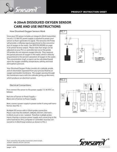
PRODUCT INSTRUCTION SHEET4-<strong>20mA</strong> <strong>DISSOLVED</strong> <strong>OXYGEN</strong> <strong>SENSOR</strong><strong>CARE</strong> <strong>AND</strong> USE INSTRUCTIONSHow Dissolved Oxygen Sensors WorkSince your DO sensor includes an integral 4-<strong>20mA</strong> transmittercircuit, a 12-36V DC power supply is required to power yoursensor so that it generates its signal. The <strong>Sensorex</strong> DO Probewill provide a milliamp signal proportional to the concentrationof oxygen in the water. See SPECIFICATIONS on page4, for preset factory output. Please note that range can beadjusted via your PLC or controller, but not at the probe.DO probes do not measure oxygen directly. They measurethe partial pressure of oxygen in the water, which is directlyproportional to the percent saturation of oxygen in the water.The concentration (mg/L or ppm) can be calculated basedupon the oxygen solubility, temperature, salinity, and totalatmospheric pressure.FIG. 1Your Dissolved Oxygen Probe consists of a cathode, anode,and an electrolyte separated from your process fluid by anoxygen permeable membrane. The oxygen passing throughthe membrane reacts with the cathode, giving up electrons,which produces an electrical current.FIG. 2Electrical ConnectionsFirst connect the sensor to the power supply (12-36 VDC) asfollows:Red wire of Sensor to Power Supply +Black wire of Sensor to Power Supply -Next, connect power supply to power outlet if using wall transformer.(See FIG. 1)Multiple DO sensor with 4-<strong>20mA</strong> probe connectionPlease note that the DO6241, D06242, DO7241, DO7242’s4-<strong>20mA</strong> circuit is non- isolated. Therefore multiple probeinputs sharing a common power supply and connecting to thesame load device (PLC,computer or controller) must be connectedto 4-<strong>20mA</strong> loop isolators as shown in FIG. 2Parts covered by this product instruction sheet include:DO6241, DO6242, DO7241, DO7242page 1 of 4FORM: 4-20DOInstruct [REV:Oct2005]©2005 <strong>SENSOR</strong>EX CORPORATION
PRODUCT INSTRUCTION SHEETGetting Your DO Sensor Ready to Use FIG. 3Remove clear wire and label from vent hole on top of DO sensoras shown in FIG 3. Discard these parts after removing.CalibrationThe simplest method to calibrate your DO sensor is in air, sinceair is saturated with oxygen. You may also bubble oxygen orair into a bucket or beaker. The sensor is pre-calibrated at thefactory (see Specifcations Section for calibration range). If youprefer a 2-point calibration, a saturated solution of sodiumsulfite (Na2SO3) is suggested. 17g Sodium sulfite in 125mLDI water is more than enough. Sodium sulfite will not reacha true zero ouput but it should reach less than 4.75mA (seeSpecifications Section for range).Labelcovering wireMembrane Types<strong>Sensorex</strong> offers two types of membrane materials for DO sensors,either PTFE or HDPE. Teflon offers excellent durabilityand moderate speed of response. HDPE offers fast responsebut less mechanical strength. The PTFE membrane also hasless membrane permeability error with temperature as comparedto HDPE. Spare membranes are available in 5 or 25counts or in DOKIT-Teflon or DOKIT-HDPE.FIG. 4Mounting Your DO SensorSubmersion mounting of the sensor is recommended. Toprevent air bubbles from becoming trapped on the membraneand producing falsely high DO readings, it is recommendedthat the sensor be mounted with the membrane pointingslightly upward (not horizontal) as shown in FIG. 4.Bubbles riseup and are nottrapped undermembraneParts covered by this product instruction sheet include:DO6241, DO6242, DO7241, DO7242Parts covered by this product instruction sheet include:DO6242T, DO6242H, DO7242T, DO7242Hpage 2 of 4FORM: 4-20DOInstruct [REV:Oct2005]©2005 <strong>SENSOR</strong>EX CORPORATION
PRODUCT INSTRUCTION SHEETSensor Re-ConditioningFIG. 5 FIG. 61. Unscrew the lower body from the upper body(FIG.5)NOTE: Industrial Dissolved Oxygen Sensors from <strong>Sensorex</strong> contain precisionmachined and molded parts. The top and bottom caps have beencustom fitted at the factory. They must be “matched” with each other toensure proper tensioning of the membrane. The bottom caps are NOTinterchangeable with other top caps.2. Safely dispose of the electrolyte that is a special reagentgrade Sodium Chloride solution (salt water) as shown inFIG. 6.3. Using the Membrane Tool, unscrew the Membrane Lockin the lower body as shown in FIG. 74. Remove and dispose of the membrane and itsO-Ring as show in FIG 8.FIG. 7FIG. 85. Using a toothbrush, dish washing powder, and cleanwater, clean the cathode, anode, and plastic betweenthem. Rinse all components thoroughly. Household Ammoniamay be used to clean the silver anode overnightIf Ammonium Hydroxide is used, expose it for no morethan 3 minutes (it is very strong). See FIG. 9.6. Install a new O-Ring into the lower body membrane cavity,then a new membrane into the lower body. Using theMembrane Tool, screw the Membrane Lock on top of themembrane as shown in FIG. 10.7.Inspect the membrane for wrinkles--replace if it iswrinkled.membranetensionermembranemembraneo-ringFIG. 9 FIG. 10discardmembranediscardo-ring8 .Pour some water into the lower body and look for leakagearound the membrane--replace it if there is leakage. Ifno leakage, dispose of the water.yellowshrink =4-<strong>20mA</strong>9. Fill the lower body to its rim with fresh Electrolyte asshown in FIG. 11.10. Inspect the large O-Ring between the upper and lowerbody. Replace it if it appears deteriorated.See FIG. 12.11. Screw the lower body onto the upper body. ExcessElectrolyte will squirt out of a small pressure balance holeatop the upper body. If no electrolyte squirts out, clearthe hole of its blockage before installing the lower body.anodecathodebrushmembranetensionermembranemembraneo-ringParts covered by this product instruction sheet include:DO6242T, DO6242H, DO7242T, DO7242Hpage 3 of 4FORM: 4-20DOInstruct [REV:Oct2005]©2005 <strong>SENSOR</strong>EX CORPORATION
PRODUCT SPECIFICATION SHEETSensor StorageIf long-term storage of probes is required, empty electrolyteout of probe leaving only a little solution on themembrane to keep it wet. Leaving a full volume of electrolytein DO probe long-term without use will depletethe probes’ anode. See section “RE-CONDITIONING YOUR<strong>DISSOLVED</strong> <strong>OXYGEN</strong> PROBE” for steps on how to openand close probe housing.FIG. 11 FIG. 12REINSTALL -RING OON TOP OF BODYIN GROOVETURN COUNTER CLOCKWISEALL TO INSTSPECIFICATIONSOutput at 100% saturation (DO6241, DO7241)PTFE membrane15-20 mAHDPE membrane15-20 mAOutput at 100% saturation (DO6242, DO7242)PTFE membrane7-10 mAHDPE membrane7-10 mA11751 Markon Dr.Garden Grove, CA 92841 USAOutput at 0% saturationPTFE membraneHDPE membraneTemperature RangeMaxMinAccuracyResponse TimePTFE membraneWater Flow RateHDPE membraneWetted MaterialsBodyMembrane4.75 +/- 0.25mA4.75 +/- 0.25mA50 deg C0 deg C+/- 2% when measuringtemp equal cal temp.6 minutes to reach90% of final reading5 minutes to reach 95% offinal readingMin 2 inch/second acrossmembrane.DelrinTeflon or HDPETel: 714-895-4344Fax: 714-894-4839E-mail: info@sensorex.comwww.sensorex.comParts covered by this product instruction sheet include:DO6241, DO6242, DO7241, DO7242page 4 of 4WiringDO6242, DO7242Power Supply RequirementTeflon and Delrin are registered trademarks of E.I. DuPont.mA output/power supplyconnection: +Red, -Black12-24V DC, 50mAFORM: 4-20DOInstruct [REV:Oct2005]©2005 <strong>SENSOR</strong>EX CORPORATION