TECHNICAL & SERVICE MANUAL Ceiling Cassettes ... - Engvent.ru
TECHNICAL & SERVICE MANUAL Ceiling Cassettes ... - Engvent.ru
TECHNICAL & SERVICE MANUAL Ceiling Cassettes ... - Engvent.ru

Create successful ePaper yourself
Turn your PDF publications into a flip-book with our unique Google optimized e-Paper software.
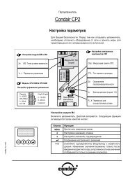
NOT AVAILABLE˚CAMPMAMPMSTAND BYDEFROSTCHECKCENTRALLY CONTROLLEDON OFFCLOCKERROR CODE1Hr.NOT AVAILABLE˚CFILTERCHECK MODETEST RUNFUNCTIONSPLIT-TYPE AIR CONDITIONERSNo.OC297<strong>TECHNICAL</strong> & <strong>SERVICE</strong> <strong>MANUAL</strong>Series PLAIndoor unit[Model names]PLA-RP3AAPLA-RP4AAPLA-RP5AAPLA-RP6AA<strong>Ceiling</strong> <strong>Cassettes</strong> R410A[Service Ref.]PLA-RP3AA.UKPLA-RP4AA.UKPLA-RP5AA.UKPLA-RP6AA.UK• Refer to the OCT04 as for controlrelation.This manual does not coveroutdoor units.When serving them, please refer tothe service manual No.OC294 andthis manual in a set.CONTENTSINDOOR UNITCHECK TEST RUNMODEL SELECT1. SAFETY PRECAUTION·······························22. PART NAMES AND FUNCTIONS ···············43. SPECIFICATIONS ········································74. DATA···························································115. OUTLINES AND DIMENSIONS ·················236. WIRING DIAGRAM ····································247. REFRIGERANT SYSTEM DIAGRAM···········258. TROUBLESHOOTING ·······························269. DISASSEMBLY PROCEDURE ··················3710. PARTS LIST ···············································4011. OPTIONAL PARTS·····································46ON/OFF TEMP˚CTEMP.ON/OFFWIRELESS REMOTECONTROLLERWIRED REMOTECONTROLLER
1 SAFETY PRECAUTIONCAUTIONS RELATED TO NEW REFRIGERANTUse new refrigerant pipes.In case of using the existing pipes for R22, be careful withthe followings.· For RP4, 5 and 6, be sure to perform replacement operationbefore test <strong>ru</strong>n.· Change flare nut to the one provided with this product.Use a newly flared pipe.· Avoid using thin pipes.Make sure that the inside and outside of refrigerantpiping is clean and it has no contaminationsuch as sulfur hazardous for use, oxides, dirt,shaving particles, etc.In addition, use pipes with specified thickness.Contamination inside refrigerant piping can cause deteriorationof refrigerant oil etc.Store the piping to be used during installationindoors and keep both ends of the piping sealeduntil just before brazing. (Leave elbow joints, etc.in their packaging.)If dirt, dust or moisture enter into refrigerant cycle, that cancause deterioration of refrigerant oil or malfunction of compressor.Use ester oil, ether oil or alkylbenzene oil (smallamount) as the refrigerant oil applied to flaresand flange connections.If large amount of mineral oil enter, that can cause deteriorationof refrigerant oil etc.Charge refrigerant from liquid phase of gascylinder.If the refrigerant is charged from gas phase, compositionchange may occur in refrigerant and the efficiency will belowered.Do not use refrigerant other than R410A.If other refrigerant (R22 etc.) is used, chlorine in refrigerantcan cause deterioration of refrigerant oil etc.Use a vacuum pump with a reverse flow checkvalve.Vacuum pump oil may flow back into refrigerant cycle andthat can cause deterioration of refrigerant oil etc.Use the following tools specifically designed fo<strong>ru</strong>se with R410A refrigerant.The following tools are necessary to use R410A refrigerant.Tools (for R410A)Gauge manifold Flare toolCharge hoseSize adjustment gaugeGas leak detector Vacuum pump adaptorTorque wrenchElectronic refrigerantcharging scaleKeep the tools with care.If dirt, dust or moisture enter into refrigerant cycle, that cancause deterioration of refrigerant oil or malfunction of compressor.Do not use a charging cylinder.If a charging cylinder is used, the composition of refrigerantwill change and the efficiency will be lowered.Ventilate the room if refrigerant leaks duringoperation. If refrigerant comes into contact witha flame, poisonous gases will be released.[1] Cautions for service(1) Perform service after collecting the refrigerant left in unit completely.(2) Do not release refrigerant in the air.(3) After completing service, charge the cycle with specified amount of refrigerant.(4) When performing service, install a filter drier simultaneously.Be sure to use a filter drier for new refrigerant.[2] Additional refrigerant chargeWhen charging directly from cylinder· Check that cylinder for R410A on the market is syphon type.· Charging should be performed with the cylinder of syphon stood vertically. (Refrigerant is charged from liquid phase.)2
UnitGravimeter[3] Service toolsUse the below service tools as exclusive tools for R410A refrigerant.No.Specifications1 Gauge manifold ·Only for R410A·Use the existing fitting specifications. (UNF1/2)·Use high-tension side pressure of 5.3MPa·G or over.2 Charge hose ·Only for R410A·Use pressure performance of 5.09MPa·G or over.3 Electronic scale4 Gas leak detector ·Use the detector for R134a, R407C or R410A.5 Adaptor for reverse flow check ·Attach on vacuum pump.6 Refrigerant charge base7 Refrigerant cylinder ·Only for R410A Top of cylinder (Pink)Cylinder with syphon8 Refrigerant recovery equipment3
2PART NAMES AND FUNCTIONS● Indoor (Main) UnitPLA-RP3AA.UK, PLA-RP4AA.UK, PLA-RP5AA.UK, PLA-RP6AA.UKHorizontal Air OutletSets airflow of horizontal automaticallyduring cooling or dehumidifying.FilterRemoves dust and pollutantsfrom intake airGrilleAuto Air Swing VaneDisperses airflow up anddown and adjusts the angleof airflow direction.● Wired remote controllerAir IntakeIntakes air from room.On the controls are set, the same operation mode can be repeated by simply pressing the ON/OFF button.PLA-RP3AA.UK, PLA-RP4AA.UK, PLA-RP5AA.UK, PLA-RP6AA.UK● Operation buttonsTEMP. ADJUSTMENT buttonThis sets the room temperature. Thetemperature setting can be performedin 1: unitsSetting rangeCooling 19: to 30:Heating 17: to 28:TIME SETTING buttonThis sets the current time, start timeand stop time.FAN SPEED buttonThis sets the ventilation fan speed.ON/OFF buttonTIMER buttonThis switches between continuousoperation and the timer operation.OPERATION SWITCH buttonPress this button to switch the cooling,electronic dry (dehumidify), automaticand heating modes.STAND BYDEFROSTPAR-20MAACHECKCENTRALLY CONTROLLEDON OFF˚CTEMP.TIMER SETCLOCKERROR CODE1Hr.˚CFILTERCHECK MODETEST RUNNOT AVAILABLE FUNCTIONON/OFFFILTERCHECK TESTThis switches between the operationand stop modes each time it is pressed.The lamp on this button lights duringoperation.AIR DIRECTION buttonThis adjusts the vertical angle of theventilation.FILTER buttonThis resets the filter service indicationdisplayLOUVER buttonThis switch the horizontal fan motionON and OFF.(Not available for this model.)VENTILATION buttonThis sets the ventilation fan speed.CHECK-TEST RUN buttonOnly press this button to perform aninspection check or test operation.Do not use it for normal operation.4
● DisplayCENTRALLYCONTROLLED displayThis indicates when the unit is controlledby optional features such ascentral control type remote controller.TIMER displayThis indicates when the continuousoperation and time operation modesare set.It also display the time for the timeroperation at the same time as whenit is set.CLOCK displayThe current time , start time and stoptime can be displayed in ten secondintervals by pressing the time switchbutton. The start time or stop time isalways displayed during the timeroperation.AIR DIRECTION displayThis displays the air direction.In this display example on the bottomleft, a condition where all displaylamps light is shown for explanationpurposes although this differsfrom actual operation.AIR SPEED displayThe selected fan speed is displayed.ROOM TEMPERATURE displayOPERATION MODE displayThis indicates the operation mode.STAND BYDEFROSTCHECKCENTRALLY CONTROLLEDON OFF˚CTEMP.CLOCKERROR CODE1Hr.˚CFILTERCHECK MODETEST RUNNOT AVAILABLE FUNCTIONON/OFFThe temperature of the suction airis displayed during operation. Thedisplay range is 8°C to 39°C. Thedisplay flashes 8°C when the actualtemperature is less than 8°C andflashes 39°C when the actual temperatureis greater than 39°C.STANDBY displayFILTERCHECK TESTOperation lampThe [STANDBY] symbol is only displayedfrom the time the heatingoperation starts unit the heated airbegins to blow.PAR-20MAATIMER SETThis lamp lights during operation,goes off when the unit stops andflashes when a malfunction occurs.DEFROST displayThis indicates when the defrost operationis performed.CHECK MODETEST RUNdisplayThis display lights in the check modeor when a test operation is performed.FILTER displayCHECK displayThis indicates when a malfunctionhas occurred in the unit which shouldbe checked.SET TEMPERATURE displayThis displays the selected settingtemperature.POWER displayThis lamp lights when electricity issupplied to the unit.This lamp lights when the filter needto be cleaned.Caution● Only the Power display lights when the unit is stopped and power supplied to the unit.● When the central control remote control unit, which is sold separately, is used the ON-OFF button, operation switch buttonand TEMP. adjustment button do not operate.● “NOT AVAILABLE” is displayed when the Air speed button are pressed.This indicates that this room unit is not equippedwith the fan direction adjustment function and the louver function.● When power is turned ON for the first time, it is normal that “H0” is displayed on the room temperature indication (For max.2minutes). Please wait until this “H0” indication disappear then start the operation.5
● Wireless remote controllerPLA-RP3AA.UK, PLA-RP4AA.UK, PLA-RP5AA.UK, PLA-RP6AA.UKCHECK TEST RUN displayCHECK&TEST RUN display indicates thatthe unit is being checked or test-<strong>ru</strong>n.MODEL SELECT displayBlinks when model is selected.displayLights up while transmission to the indoo<strong>ru</strong>nit is mode using switches.displaySET TEMP. display indicates desired temperatureset.displayOPERATION MODE displayOperation mode display indicates which operationmode is in effect.displayThe vertical direction of air flow is indicated.displayFAN SPEED display indicates which fanspeed has been selected.ON/OFF buttonThe unit is turned ON and OFF alternatelyeach time the button is pressed.FAN SPEED SELECT buttonUsed to change the fan speed.MODE SELECT buttonUsed to switch the operation mode betweencooling, drying, blowing, heating and automode.w In case the outdoor unit is cool only type,the heating mode is not available.CHECK-TEST RUN buttonOnly press this button to perform an inspectioncheck or test operation.Do not use it for normal operation.VANE CONTROL buttonUsed to change the air flow direction.ON/OFF TEMPMODECHECKCHECK TEST RUNMODEL SELECT ˚CAMPMAMPMNOT AVAILABLEFAN AUTO STOPVANE AUTO STARTLOUVER hTEST RUNminSET RESET CLOCKCLOCK displayDisplays the current time.TIMER displayDisplays when in timer operation or whensetting timer.“ ” “ ” displayDisplays the order of timer operation.“ ” “ ” displayDisplays whether timer is on or off.buttonSET TEMPERATURE button sets any desiredroom temperature.TIMER CONTROL buttonsAUTO STOP (OFF timer): when this switchis set, the air conditioner will be automaticallystopped at the preset time.AUTO START (ON timer): when this switchis set, the air conditioner will be automaticallystarted at the preset time.h and min buttonsButtons used to set the “hour and minute” ofthe current time and timer settings.LOUVER buttonThis switch the horizontal fan motion ONand OFF.(Not available for this model.)CLOCK buttonRESET buttonSET button6
3SPECIFICATIONSService Ref.ItemFunctionCapacityBtu/hWTotal inputkWService Ref.Power supply (phase, cycle,voltage)InputRunning currentkWAStarting current AExternal finish (Panel)Heat exchangerFan (drive) o No.FanFan motor outputkWAirflow (Lo-Mi2-Mi1-Hi) K / min (CFM)External static pressure Pa (mmAq)Booster heaterkWOperation control & ThermostatSound level (Lo-Mi2-Mi1-Hi)dBUnit drain pipe I.D.mm (in.)Wmm (in.)DimensionsDmm (in.)Hmm (in.)Weightkg (lbs.)Service Ref.Power supply (phase, cycle, voltage)Running currentAExternal finishRefrigerant controlCompressorModelMotor outputkWStarter typeProtection devicesHeat exchangerFan (drive) o No.Fan Fan motor output kWAirflowK/ min (CFM)Crankcase heaterWDefrost methodSound levelCoolingdBHeatingdBWmm (in.)DimensionsDmm (in.)Hmm (in.)Weightkg (lbs.)RefrigerantChargekg (lbs.)Oil (Model)LPipe size O.D.Liquid mm (in.)Gasmm (in.)Connection methodIndoor sideOutdoor sideBetween the indoor & Height differenceoutdoor units Piping lengthIndoor unitOutdoor unitRefrigerant pipingPLA-RP3AA.UKCoolingHeating24,200 27,3007,100 (3,300~8,100) 8,000 (3,500~10,200)1.97 2.34PLA-RP3AA.UKSingle phase, 50Hz, 220-230-240V0.16 0.160.79 0.791.0 1.0Munsell 0.70Y 8.59/0.97Plate fin coilTurbo fan (direct) o10.07015-16-18-20 (530-565-635-705)0 (direct blow)—Remote controller & built-in28-30-32-3432 (1-1/4)UNIT : 840 (33-1/16) PANEL : 950 (37-3/8)UNIT : 840 (33-1/16) PANEL : 950 (37-3/8)UNIT : 258 (10-1/2) PANEL : 30 (1-3/16)UNIT : 24 (53) PANEL: 5 (11)PUHZ-RP3VHASingle phase, 50Hz, 220-230-240V8.04 9.74Munsell 3Y 7.8/1.1Linear expansion valveHermeticTNB220FMBH1.6Line startHP switch, Discharge thermo.Plate fin coilPropeller (direct) o10.06055 (1,940)—Reverse cycle4748950 (37-3/8)330+30 (13+1-3/16)943 (37-1/8)75 (165)R410A3.5 (7.7)0.87 (NEO22)9.52 (3/8)15.88 (5/8)FlaredFlaredMax. 30mMax. 50mNOTE: 1. Rating conditions (ISO T1)Cooling Indoor : D.B. 27: (80˚F) W.B. 19: (66˚F) Outdoor : D.B. 35: (95˚F) W.B. 24: (75˚F)Heating Indoor : D.B. 20: (68˚F) Outdoor : D.B. 7: (45˚F) W.B. 6: (43˚F)Refrigerant piping length (one way) : 5m (16ft.)2. Guaranteed operating range3. Above data based on indicated voltageIndoor OutdoorIndoor unit Single phase 230V 50HzUpper limitOutdoor unitD.B. 35˚C, W.B. 22.5˚CSingle phase 230V 50HzD.B. 46˚CCoolingLower limit D.B. 19˚C, W.B. 15˚C D.B. -5˚CHeatingUpper limit D.B. 28˚C D.B. 21˚C, W.B. 15˚CLower limit D.B. 17˚C D.B. -11˚C, W.B. -12˚C7
ItemFunctionCapacityTotal inputIndoor unitOutdoor unitRefrigerant pipingService Ref.Btu/hWkWService Ref.Power supply (phase, cycle,voltage)InputRunning currentkWAStarting current AExternal finish (Panel)Heat exchangerFan (drive) o No.FanFan motor outputkWAirflow (Lo-Mi2-Mi1-Hi) K / min (CFM)External static pressure Pa (mmAq)Booster heaterkWOperation control & ThermostatSound level (Lo-Mi2-Mi1-Hi)dBUnit drain pipe I.D.mm (in.)Wmm (in.)DimensionsDmm (in.)Hmm (in.)Weightkg (lbs.)Service Ref.Power supply (phase, cycle, voltage)Running currentAExternal finishRefrigerant controlCompressorModelMotor outputkWStarter typeProtection devicesHeat exchangerFan (drive) o No.Fan Fan motor output kWAirflowK / min (CFM)Crankcase heaterWDefrost methodSound levelCoolingdBHeatingdBWmm (in.)DimensionsDmm (in.)Hmm (in.)Weightkg (lbs.)RefrigerantChargekg (lbs.)Oil (Model)LPipe size O.D.Liquid mm (in.)Gasmm (in.)Connection methodIndoor sideOutdoor sideBetween the indoor & Height differenceoutdoor units Piping lengthIndoor OutdoorCoolingUpper limit D.B. 35˚C, W.B. 22.5˚C D.B. 46˚CLower limit D.B. 19˚C, W.B. 15˚C D.B. -5˚CHeatingUpper limit D.B. 28˚C D.B. 21˚C, W.B. 15˚CLower limit D.B. 17˚C D.B. -11˚C, W.B. -12˚CPLA-RP4AA.UKCooling Heating34,100 38,20010,000 (5,000~11,400) 11,200 (5,600~14,000)3.03 3.39PLA-RP4AA.UKSingle phase, 50Hz, 220-230-240V0.25 0.251.25 1.252.0 2.0Munsell 0.70Y 8.59/0.97Plate fin coilTurbo fan (direct) o10.12020-23-26-28 (705-810-920-990)0 (direct blow)—Remote controller & built-in33-36-39-4132 (1-1/4)UNIT : 840 (33-1/16) PANEL : 950 (37-3/8)UNIT : 840 (33-1/16) PANEL : 950 (37-3/8)UNIT : 298 (11-3/4) PANEL : 30 (1-3/16)UNIT : 30 (66) PANEL : 5 (11)PUHZ-RP4VHASingle phase, 50Hz, 220-230-240V12.33 13.94Munsell 3Y 7.8/1.1Linear expansion valveHermeticANV33FDAMT1.9Line startHP switch, LP switch, Discharge thermo.Plate fin coilPropeller (direct) o20.060+0.060100 (3,530)—Reverse cycle4951950 (37-3/8)330+30 (13+1-3/16)1,350 (53-1/8)121 (267)R410A5.5 (12.1)1.4 (MEL56)9.52 (3/8)15.88 (5/8)FlaredFlaredMax. 30mMax. 75mNOTE: 1. Rating conditions (ISO T1)Cooling Indoor : D.B. 27: (80˚F) W.B. 19: (66˚F) Outdoor : D.B. 35: (95˚F) W.B. 24: (75˚F)Heating Indoor : D.B. 20: (68˚F) Outdoor : D.B. 7: (45˚F) W.B. 6: (43˚F)Refrigerant piping length (one way) : 5m (16ft.)2. Guaranteed operating range 3. Above data based on indicated voltageIndoor unitOutdoor unitSingle phase 230V 50HzSingle phase 230V 50Hz8
ItemService Ref.FunctionCapacityBtu/hWTotal inputkWService Ref.Power supply (phase, cycle,voltage)InputRunning currentkWAStarting current AExternal finish (Panel)Heat exchangerFan (drive) o No.FanFan motor outputkWAirflow (Lo-Mi2-Mi1-Hi) K / min (CFM)External static pressure Pa (mmAq)Booster heaterkWOperation control & ThermostatSound level (Lo-Mi2-Mi1-Hi)dBUnit drain pipe I.D.mm (in.)Wmm (in.)DimensionsDmm (in.)Hmm (in.)Weightkg (lbs.)Service Ref.Power supply (phase, cycle, voltage)Running currentAExternal finishRefrigerant controlCompressorModelMotor outputkWStarter typeProtection devicesHeat exchangerFan (drive) o No.Fan Fan motor output kWAirflowK / min (CFM)Crankcase heaterWDefrost methodSound levelCoolingdBHeatingdBWmm (in.)DimensionsDmm (in.)Hmm (in.)Weightkg (lbs.)RefrigerantChargekg (lbs.)Oil (Model)LPipe size O.D.Liquid mm (in.)Gasmm (in.)Connection methodIndoor sideOutdoor sideBetween the indoor & Height differenceoutdoor units Piping lengthIndoor unitOutdoor unitRefrigerant pipingPLA-RP5AA.UKCooling Heating42,700 47,80012,500 (6,000~14,000) 14,000 (6,000~16,000)3.89 4.27PLA-RP5AA.UKSingle phase, 50Hz, 220-230-240V0.33 0.331.64 1.642.0 2.0Munsell 0.70Y 8.59/0.97Plate fin coilTurbo fan (direct) o10.12022-25-28-30 (775-880-990-1,060)0 (direct blow)—Remote controller & built-in37-40-43-4532 (1-1/4)UNIT : 840 (33-1/16) PANEL : 950 (37-3/8)UNIT : 840 (33-1/16) PANEL : 950 (37-3/8)UNIT : 298 (11-3/4) PANEL : 30 (1-3/16)UNIT : 32 (71) PANEL : 5 (11)PUHZ-RP5VHASingle phase, 50Hz, 220-230-240V15.80 17.50Munsell 3Y 7.8/1.1Linear expansion valveHermeticANV33FDAMT2.4Line startHP switch, LP switch, Discharge thermo.Plate fin coilPropeller (direct) o20.060+0.060100 (3,530)—Reverse cycle5052950 (37-3/8)330+30 (13+1-3/16)1,350 (53-1/8)121 (267)R410A5.5 (12.1)1.4 (MEL56)9.52 (3/8)15.88 (5/8)FlaredFlaredMax. 30mMax. 75mNOTE: 1. Rating conditions (ISO T1)Cooling : Indoor: D.B. 27: (80˚F) W.B. 19: (66˚F) Outdoor: D.B. 35: (95˚F) W.B. 24: (75˚F)Heating : Indoor: D.B. 20: (68˚F) Outdoor: D.B. 7: (45˚F) W.B. 6: (43˚F)Refrigerant piping length (one way) : 5m (16ft.)2. Guaranteed operating range3. Above data based on indicated voltageIndoor unit Single phase 230V 50HzIndoor OutdoorOutdoor unit Single phase 230V 50HzUpper limit D.B. 35:, W.B. 22.5: D.B. 46:CoolingLower limit D.B. 19 :, W.B. 15: D.B. -5:HeatingUpper limit D.B. 28: D.B. 21:, W.B. 15:Lower limit D.B. 17: D.B. -11:, W.B. -12:9
ItemFunctionCapacityIndoor unitOutdoor unitRefrigerant pipingService Ref.Btu/hWkWTotal inputService Ref.Power supply (phase, cycle,voltage)InputkWRunning current AStarting current AExternal finish (Panel)Heat exchangerFan (drive) o No.FanFan motor outputkWAirflow (Lo-Mi2-Mi1-Hi) K / min (CFM)External static pressure Pa (mmAq)Booster heaterkWOperation control & ThermostatSound level (Lo-Mi2-Mi1-Hi)dBUnit drain pipe I.D.mm (in.)Wmm (in.)DimensionsDmm (in.)Hmm (in.)Weightkg (lbs.)Service Ref.Power supply (phase, cycle, voltage)Running currentAExternal finishRefrigerant controlCompressorModelMotor outputkWStarter typeProtection devicesHeat exchangerFan (drive) o No.Fan Fan motor output kWAirflowK / min (CFM)Crankcase heaterWDefrost methodSound levelCoolingdBHeatingdBWmm (in.)DimensionsDmm (in.)Hmm (in.)Weightkg (lbs.)RefrigerantChargekg (lbs.)Oil (Model)LPipe size O.D.Liquid mm (in.)Gasmm (in.)Connection methodIndoor sideOutdoor sideBetween the indoor & Height differenceoutdoor units Piping lengthPLA-RP6AA.UKCooling Heating47,800 54,60014,000 (6,200~15,300) 16,000 (6,200~18,000)4.99 4.91PLA-RP6AA.UKSingle phase, 50Hz, 220-230-240V0.33 0.331.64 1.642.0 2.0Munsell 0.70Y 8.59/0.97Plate fin coilTurbo fan (direct) o10.12022-25-28-30 (775-880-990-1,060)0 (direct blow)—Remote controller & built-in37-40-43-4532 (1-1/4)UNIT : 840 (33-1/16) PANEL : 950 (37-3/8)UNIT : 840 (33-1/16) PANEL : 950 (37-3/8)UNIT : 298 (11-3/4) PANEL : 30 (1-3/16)UNIT : 32 (71) PANEL : 5 (11)PUHZ-RP6VHASingle phase, 50Hz, 220-230-240V20.73 20.37Munsell 3Y 7.8/1.1Linear expansion valveHermeticANV33FDAMT2.9Line startHP switch, LP switch, Discharge thermo.Plate fin coilPropeller (direct) o20.060+0.060100 (3,530)—Reverse cycle5052950 (37-3/8)330+30 (13+1-3/16)1,350 (53-1/8)121 (267)R410A5.5 (12.1)1.4 (MEL56)9.52 (3/8)15.88 (5/8)FlaredFlaredMax. 30mMax. 75mNOTE: 1. Rating conditions (ISO T1)Cooling : Indoor: D.B. 27: (80˚F) W.B. 19: (66˚F) Outdoor: D.B. 35: (95˚F) W.B. 24: (75˚F)Heating : Indoor: D.B. 20: (68˚F) Outdoor: D.B. 7: (45˚F) W.B. 6: (43˚F)Refrigerant piping length (one way) : 5m (16ft.)2. Guaranteed operating range3. Above data based on indicated voltageIndoor unit Single phase 230V 50HzIndoor OutdoorOutdoor unit Single phase 230V 50HzUpper limit D.B. 35:, W.B. 22.5: D.B. 46:CoolingLower limit D.B. 19 :, W.B. 15: D.B. -5:HeatingUpper limit D.B. 28: D.B. 21 :, W.B. 15:Lower limit D.B. 17: D.B. -11:, W.B. -12:10
11DATA44-1. PERFORMANCE DATA4-1-1. COOLING CAPACITY (1)PLA-RP3AA.UK / PUHZ-RP3VHA(230V)NOTE: CA: Capacity (W) SHC: Sensible heat capacity (W)P.C.: Power consumption (kW)SHF: Sensible heat factor20202022222224242424262626262727272728282828303030303232323234343434161820161820161820221618202216182022161820221618202216182022161820227,0297,5268,0947,0297,5268,0947,0297,5268,0948,6277,0297,5268,0948,6277,0297,5268,0948,6277,0297,5268,0948,6277,0297,5268,0948,6277,0297,5268,0948,6277,0297,5268,0948,6274,4993,9143,2385,0614,5163,8855,6235,1184,5333,7966,1865,7205,1804,4866,4676,0215,5044,8316,7486,3225,8285,1767,0296,9246,4755,8667,0297,5267,1236,5567,0297,5267,7707,2460.640.520.400.720.600.480.800.680.560.440.880.760.640.520.920.800.680.560.960.840.720.601.000.920.800.681.001.000.880.761.001.000.960.841.581.611.651.581.611.651.581.611.651.691.581.611.651.691.581.611.651.691.581.611.651.691.581.611.651.691.581.611.651.691.581.611.651.696,8167,3137,9176,8167,3137,9176,8167,3137,9178,4496,8167,3137,9178,4496,8167,3137,9178,4496,8167,3137,9178,4496,8167,3137,9178,4496,8167,3137,9178,4496,8167,3137,9178,4494,3623,8033,1674,9084,3883,8005,4534,9734,4333,7185,9985,5585,0674,3936,2715,8505,3834,7316,5436,1435,7005,0696,8166,7286,3335,7456,8167,3136,9676,4216,8167,3137,6007,0970.640.520.400.720.600.480.800.680.560.440.880.760.640.520.920.800.680.560.960.840.720.601.000.920.800.681.001.000.880.761.001.000.960.841.661.691.731.661.691.731.661.691.731.791.661.691.731.791.661.691.731.791.661.691.731.791.661.691.731.791.661.691.731.791.661.691.731.796,6037,0657,7046,6037,0657,7046,6037,0657,7048,2366,6037,0657,7048,2366,6037,0657,7048,2366,6037,0657,7048,2366,6037,0657,7048,2366,6037,0657,7048,2366,6037,0657,7048,2364,2263,6743,0814,7544,2393,6985,2824,8044,3143,6245,8115,3694,9304,2836,0755,6525,2384,6126,3395,9345,5474,9426,6036,4996,1635,6006,6037,0656,7796,2596,6037,0657,3956,9180.640.520.400.720.600.480.800.680.560.440.880.760.640.520.920.800.680.560.960.840.720.601.000.920.800.681.001.000.880.761.001.000.960.841.761.811.851.761.811.851.761.811.851.911.761.811.851.911.761.811.851.911.761.811.851.911.761.811.851.911.761.811.851.911.761.811.851.91CAIndoorintake airD.B.(˚C)Indoorintake airW.B.(˚C)20 25 30Outdoor intale air D.B.(˚C)SHC SHF P.C. CA SHC SHF P.C. CA SHC SHF P.C.
12COOLING CAPACITY (2)PLA-RP3AA.UK / PUHZ-RP3VHA(230V)NOTE: CA: Capacity (W) SHC: Sensible heat capacity (W)P.C.: Power consumption (kW)SHF: Sensible heat factor20202022222224242424262626262727272728282828303030303232323234343434161820161820161820221618202216182022161820221618202216182022161820226,3196,8167,3846,3196,8167,3846,3196,8167,3847,9526,3196,8167,3847,9526,3196,8167,3847,9526,3196,8167,3847,9526,3196,8167,3847,9526,3196,8167,3847,9526,3196,8167,3847,9524,0443,5442,9544,5504,0903,5445,0554,6354,1353,4995,5615,1804,7264,1355,8135,4535,0214,4536,0665,7255,3164,7716,3196,2715,9075,4076,3196,8166,4986,0446,3196,8167,0896,6800.640.520.400.720.600.480.800.680.560.440.880.760.640.520.920.800.680.560.960.840.720.601.000.920.800.681.001.000.880.761.001.000.960.841.891.941.991.891.941.991.891.941.992.031.891.941.992.031.891.941.992.031.891.941.992.031.891.941.992.031.891.941.992.031.891.941.992.036,0356,6037,1006,0356,6037,1006,0356,6037,1007,6686,0356,6037,1007,6686,0356,6037,1007,6686,0356,6037,1007,6686,0356,6037,1007,6686,0356,6037,1007,6686,0356,6037,1007,6683,8623,4342,8404,3453,9623,4084,8284,4903,9763,3745,3115,0184,5443,9875,5525,2824,8284,2945,7945,5475,1124,6016,0356,0755,6805,2146,0356,6036,2485,8286,0356,6036,8166,4410.640.520.400.720.600.480.800.680.560.440.880.760.640.520.920.800.680.560.960.840.720.601.000.920.800.681.001.000.880.761.001.000.960.842.032.092.132.032.092.132.032.092.132.192.032.092.132.192.032.092.132.192.032.092.132.192.032.092.132.192.032.092.132.192.032.092.132.195,7516,1776,6745,7516,1776,6745,7516,1776,6747,2425,7516,1776,6747,2425,7516,1776,6747,2425,7516,1776,6747,2425,7516,1776,6747,2425,7516,1776,6747,2425,7516,1776,6747,2423,6813,2122,6704,1413,7063,2044,6014,2003,7373,1865,0614,6954,2713,7665,2914,9424,5384,0565,5215,1894,8054,3455,7515,6835,3394,9255,7516,1775,8735,5045,7516,1776,4076,0830.640.520.400.720.600.480.800.680.560.440.880.760.640.520.920.800.680.560.960.840.720.601.000.920.800.681.001.000.880.761.001.000.960.842.202.252.292.202.252.292.202.252.292.322.202.252.292.322.202.252.292.322.202.252.292.322.202.252.292.322.202.252.292.322.202.252.292.32CAIndoorintake airD.B.(˚C)Indoorintake airW.B.(˚C)35 40 45Outdoor intale air D.B.(˚C)SHC SHF P.C. CA SHC SHF P.C. CA SHC SHF P.C.
13COOLING CAPACITY (3)PLA-RP4AA.UK / PUHZ-RP4VHA(230V)NOTE: CA: Capacity (W) SHC: Sensible heat capacity (W)P.C.: Power consumption (kW)SHF: Sensible heat factor20202022222224242424262626262727272728282828303030303232323234343434161820161820161820221618202216182022161820221618202216182022161820229,90010,60011,4009,90010,60011,4009,90010,60011,40012,1509,90010,60011,40012,1509,90010,60011,40012,1509,90010,60011,40012,1509,90010,60011,40012,1509,90010,60011,40012,1509,90010,60011,40012,1506,4355,6184,6747,2276,4665,5868,0197,3146,4985,4688,8118,1627,4106,4409,2078,5867,8666,9269,6039,0108,3227,4129,9009,8589,2348,3849,90010,60010,1469,3569,90010,60011,05810,3280.650.530.410.730.610.490.810.690.570.450.890.770.650.530.930.810.690.570.970.850.730.611.000.930.810.691.001.000.890.771.001.000.970.852.422.472.552.422.472.552.422.472.552.612.422.472.552.612.422.472.552.612.422.472.552.612.422.472.552.612.422.472.552.612.422.472.552.619,60010,30011,1509,60010,30011,1509,60010,30011,15011,9009,60010,30011,15011,9009,60010,30011,15011,9009,60010,30011,15011,9009,60010,30011,15011,9009,60010,30011,15011,9009,60010,30011,15011,9006,2405,4594,5727,0086,2835,4647,7767,1076,3565,3558,5447,9317,2486,3078,9288,3437,6946,7839,3128,7558,1407,2599,6009,5799,0328,2119,60010,3009,9249,1639,60010,30010,81610,1150.650.530.410.730.610.490.810.690.570.450.890.770.650.530.930.810.690.570.970.850.730.611.000.930.810.691.001.000.890.771.001.000.970.852.562.612.672.562.612.672.562.612.672.762.562.612.672.762.562.612.672.762.562.612.672.762.562.612.672.762.562.612.672.762.562.612.672.769,3009,95010,8509,3009,95010,8509,3009,95010,85011,6009,3009,95010,85011,6009,3009,95010,85011,6009,3009,95010,85011,6009,3009,95010,85011,6009,3009,95010,85011,6009,3009,95010,85011,6006,0455,2744,4496,7896,0705,3177,5336,8666,1855,2208,2777,6627,0536,1488,6498,0607,4876,6129,0218,4587,9217,0769,3009,2548,7898,0049,3009,9509,6578,9329,3009,95010,5259,8600.650.530.410.730.610.490.810.690.570.450.890.770.650.530.930.810.690.570.970.850.730.611.000.930.810.691.001.000.890.771.001.000.970.852.712.792.852.712.792.852.712.792.852.942.712.792.852.942.712.792.852.942.712.792.852.942.712.792.852.942.712.792.852.942.712.792.852.94CAIndoorintake airD.B.(˚C)Indoorintake airW.B.(˚C)20 25 30Outdoor intale air D.B.(˚C)SHC SHF P.C. CA SHC SHF P.C. CA SHC SHF P.C.
14COOLING CAPACITY (4)PLA-RP4AA.UK / PUHZ-RP4VHA(230V)NOTE: CA: Capacity (W) SHC: Sensible heat capacity (W)P.C.: Power consumption (kW)SHF: Sensible heat factor20202022222224242424262626262727272728282828303030303232323234343434161820161820161820221618202216182022161820221618202216182022161820228,9009,60010,4008,9009,60010,4008,9009,60010,40011,2008,9009,60010,40011,2008,9009,60010,40011,2008,9009,60010,40011,2008,9009,60010,40011,2008,9009,60010,40011,2008,9009,60010,40011,2005,7855,0884,2646,4975,8565,0967,2096,6245,9285,0407,9217,3926,7605,9368,2777,7767,1766,3848,6338,1607,5926,8328,9008,9288,4247,7288,9009,6009,2568,6248,9009,60010,0889,5200.650.530.410.730.610.490.810.690.570.450.890.770.650.530.930.810.690.570.970.850.730.611.000.930.810.691.001.000.890.771.001.000.970.852.912.983.062.912.983.062.912.983.063.122.912.983.063.122.912.983.063.122.912.983.063.122.912.983.063.122.912.983.063.122.912.983.063.128,5009,30010,0008,5009,30010,0008,5009,30010,00010,8008,5009,30010,00010,8008,5009,30010,00010,8008,5009,30010,00010,8008,5009,30010,00010,8008,5009,30010,00010,8008,5009,30010,00010,8005,5254,9294,1006,2055,6734,9006,8856,4175,7004,8607,5657,1616,5005,7247,9057,5336,9006,1568,2457,9057,3006,5888,5008,6498,1007,4528,5009,3008,9008,3168,5009,3009,7009,1800.650.530.410.730.610.490.810.690.570.450.890.770.650.530.930.810.690.570.970.850.730.611.000.930.810.691.001.000.890.771.001.000.970.853.123.213.273.123.213.273.123.213.273.363.123.213.273.363.123.213.273.363.123.213.273.363.123.213.273.363.123.213.273.363.123.213.273.368,1008,7009,4008,1008,7009,4008,1008,7009,40010,2008,1008,7009,40010,2008,1008,7009,40010,2008,1008,7009,40010,2008,1008,7009,40010,2008,1008,7009,40010,2008,1008,7009,40010,2005,2654,6113,8545,9135,3074,6066,5616,0035,3584,5907,2096,6996,1105,4067,5337,0476,4865,8147,8577,3956,8626,2228,1008,0917,6147,0388,1008,7008,3667,8548,1008,7009,1188,6700.650.530.410.730.610.490.810.690.570.450.890.770.650.530.930.810.690.570.970.850.730.611.000.930.810.691.001.000.890.771.001.000.970.853.383.453.513.383.453.513.383.453.513.583.383.453.513.583.383.453.513.583.383.453.513.583.383.453.513.583.383.453.513.583.383.453.513.58CAIndoorintake airD.B.(˚C)Indoorintake airW.B.(˚C)35 40 45Outdoor intale air D.B.(˚C)SHC SHF P.C. CA SHC SHF P.C. CA SHC SHF P.C.
15COOLING CAPACITY (5)PLA-RP5AA.UK / PUHZ-RP5VHA(230V)NOTE: CA: Capacity (W) SHC: Sensible heat capacity (W)P.C.: Power consumption (kW)SHF: Sensible heat factor202020222222242424242626262627272727282828283030303032323232343434341618201618201618202216182022161820221618202216182022161820221618202212,37513,25014,25012,37513,25014,25012,37513,25014,25015,18812,37513,25014,25015,18812,37513,25014,25015,18812,37513,25014,25015,18812,37513,25014,25015,18812,37513,25014,25015,18812,37513,25014,25015,1887,9206,8905,7008,9107,9506,8409,9009,0107,9806,68310,89010,0709,1207,89811,38510,6009,6908,50511,88011,13010,2609,11312,37512,19011,40010,32812,37513,25012,54011,54312,37513,25013,68012,7580.640.520.400.720.600.480.800.680.560.440.880.760.640.520.920.800.680.560.960.840.720.601.000.920.800.681.001.000.880.761.001.000.960.843.113.173.273.113.173.273.113.173.273.353.113.173.273.353.113.173.273.353.113.173.273.353.113.173.273.353.113.173.273.353.113.173.273.3512,00012,87513,93812,00012,87513,93812,00012,87513,93814,87512,00012,87513,93814,87512,00012,87513,93814,87512,00012,87513,93814,87512,00012,87513,93814,87512,00012,87513,93814,87512,00012,87513,93814,8757,6806,6955,5758,6407,7256,6909,6008,7557,8056,54510,5609,7858,9207,73511,04010,3009,4788,33011,52010,81510,0358,92512,00011,84511,15010,11512,00012,87512,26511,30512,00012,87513,38012,4950.640.520.400.720.600.480.800.680.560.440.880.760.640.520.920.800.680.560.960.840.720.601.000.920.800.681.001.000.880.761.001.000.960.843.293.353.423.293.353.423.293.353.423.543.293.353.423.543.293.353.423.543.293.353.423.543.293.353.423.543.293.353.423.543.293.353.423.5411,62512,43813,56311,62512,43813,56311,62512,43813,56314,50011,62512,43813,56314,50011,62512,43813,56314,50011,62512,43813,56314,50011,62512,43813,56314,50011,62512,43813,56314,50011,62512,43813,56314,5007,4406,4685,4258,3707,4636,5109,3008,4587,5956,38010,2309,4538,6807,54010,6959,9509,2238,12011,16010,4489,7658,70011,62511,44310,8509,86011,62512,43811,93511,02011,62512,43813,02012,1800.640.520.400.720.600.480.800.680.560.440.880.760.640.520.920.800.680.560.960.840.720.601.000.920.800.681.001.000.880.761.001.000.960.843.483.583.663.483.583.663.483.583.663.773.483.583.663.773.483.583.663.773.483.583.663.773.483.583.663.773.483.583.663.773.483.583.663.77CAIndoorintake airD.B.(˚C)Indoorintake airW.B.(˚C)20 25 30Outdoor intale air D.B.(˚C)SHC SHF P.C. CA SHC SHF P.C. CA SHC SHF P.C.
16COOLING CAPACITY (6)PLA-RP5AA.UK / PUHZ-RP5VHA(230V)NOTE: CA: Capacity (W) SHC: Sensible heat capacity (W)P.C.: Power consumption (kW)SHF: Sensible heat factor202020222222242424242626262627272727282828283030303032323232343434341618201618201618202216182022161820221618202216182022161820221618202211,12512,00013,00011,12512,00013,00011,12512,00013,00014,00011,12512,00013,00014,00011,12512,00013,00014,00011,12512,00013,00014,00011,12512,00013,00014,00011,12512,00013,00014,00011,12512,00013,00014,0007,1206,2405,2008,0107,2006,2408,9008,1607,2806,1609,7909,1208,3207,28010,2359,6008,8407,84010,68010,0809,3608,40011,12511,04010,4009,52011,12512,00011,44010,64011,12512,00012,48011,7600.640.520.400.720.600.480.800.680.560.440.880.760.640.520.920.800.680.560.960.840.720.601.000.920.800.681.001.000.880.761.001.000.960.843.733.833.933.733.833.933.733.833.934.013.733.833.934.013.733.833.934.013.733.833.934.013.733.833.934.013.733.833.934.013.733.833.934.0110,62511,62512,50010,62511,62512,50010,62511,62512,50013,50010,62511,62512,50013,50010,62511,62512,50013,50010,62511,62512,50013,50010,62511,62512,50013,50010,62511,62512,50013,50010,62511,62512,50013,5006,8006,0455,0007,6506,9756,0008,5007,9057,0005,9409,3508,8358,0007,0209,7759,3008,5007,56010,2009,7659,0008,10010,62510,69510,0009,18010,62511,62511,00010,26010,62511,62512,00011,3400.640.520.400.720.600.480.800.680.560.440.880.760.640.520.920.800.680.560.960.840.720.601.000.920.800.681.001.000.880.761.001.000.960.844.014.124.204.014.124.204.014.124.204.324.014.124.204.324.014.124.204.324.014.124.204.324.014.124.204.324.014.124.204.324.014.124.204.3210,12510,87511,75010,12510,87511,75010,12510,87511,75012,75010,12510,87511,75012,75010,12510,87511,75012,75010,12510,87511,75012,75010,12510,87511,75012,75010,12510,87511,75012,75010,12510,87511,75012,7506,4805,6554,7007,2906,5255,6408,1007,3956,5805,6108,9108,2657,5206,6309,3158,7007,9907,1409,7209,1358,4607,65010,12510,0059,4008,67010,12510,87510,3409,69010,12510,87511,28010,7100.640.520.400.720.600.480.800.680.560.440.880.760.640.520.920.800.680.560.960.840.720.601.000.920.800.681.001.000.880.761.001.000.960.844.344.434.514.344.434.514.344.434.514.594.344.434.514.594.344.434.514.594.344.434.514.594.344.434.514.594.344.434.514.594.344.434.514.59CAIndoorintake airD.B.(˚C)Indoorintake airW.B.(˚C)35 40 45Outdoor intale air D.B.(˚C)SHC SHF P.C. CA SHC SHF P.C. CA SHC SHF P.C.
17COOLING CAPACITY (7)PLA-RP6AA.UK / PUHZ-RP6VHA(230V)NOTE: CA: Capacity (W) SHC: Sensible heat capacity (W)P.C.: Power consumption (kW)SHF: Sensible heat factor202020222222242424242626262627272727282828283030303032323232343434341618201618201618202216182022161820221618202216182022161820221618202213,86014,84015,96013,86014,84015,96013,86014,84015,96017,01013,86014,84015,96017,01013,86014,84015,96017,01013,86014,84015,96017,01013,86014,84015,96017,01013,86014,84015,96017,01013,86014,84015,96017,0108,4557,2725,9059,5638,4597,18210,6729,6468,4596,97411,78110,8339,7368,33512,33511,42710,3749,01512,89012,02011,0129,69613,86013,20812,28911,05713,86014,39513,56612,41713,86014,84014,84313,7780.610.490.370.690.570.450.770.650.530.410.850.730.610.490.890.770.650.530.930.810.690.571.000.890.770.651.000.970.850.731.001.000.930.813.994.074.193.994.074.193.994.074.194.293.994.074.194.293.994.074.194.293.994.074.194.293.994.074.194.293.994.074.194.293.994.074.194.2913,44014,42015,61013,44014,42015,61013,44014,42015,61016,66013,44014,42015,61016,66013,44014,42015,61016,66013,44014,42015,61016,66013,44014,42015,61016,66013,44014,42015,61016,66013,44014,42015,61016,6608,1987,0665,7769,2748,2197,02510,3499,3738,2736,83111,42410,5279,5228,16311,96211,10310,1478,83012,49911,68010,7719,49613,44012,83412,02010,82913,44013,98713,26912,16213,44014,42014,51713,4950.610.490.370.690.570.450.770.650.530.410.850.730.610.490.890.770.650.530.930.810.690.571.000.890.770.651.000.970.850.731.001.000.930.814.224.294.394.224.294.394.224.294.394.544.224.294.394.544.224.294.394.544.224.294.394.544.224.294.394.544.224.294.394.544.224.294.394.5413,02013,93015,19013,02013,93015,19013,02013,93015,19016,24013,02013,93015,19016,24013,02013,93015,19016,24013,02013,93015,19016,24013,02013,93015,19016,24013,02013,93015,19016,24013,02013,93015,19016,2407,9426,8265,6208,9847,9406,83610,0259,0558,0516,65811,06710,1699,2667,95811,58810,7269,8748,60712,10911,28310,4819,25713,02012,39811,69610,55613,02013,51212,91211,85513,02013,93014,12713,1540.610.490.370.690.570.450.770.650.530.410.850.730.610.490.890.770.650.530.930.810.690.571.000.890.770.651.000.970.850.731.001.000.930.814.474.594.694.474.594.694.474.594.694.844.474.594.694.844.474.594.694.844.474.594.694.844.474.594.694.844.474.594.694.844.474.594.694.84CAIndoorintake airD.B.(˚C)Indoorintake airW.B.(˚C)20 25 30Outdoor intale air D.B.(˚C)SHC SHF P.C. CA SHC SHF P.C. CA SHC SHF P.C.
18COOLING CAPACITY (8)PLA-RP6AA.UK / PUHZ-RP6VHA(230V)NOTE: CA: Capacity (W) SHC: Sensible heat capacity (W)P.C.: Power consumption (kW)SHF: Sensible heat factor202020222222242424242626262627272727282828283030303032323232343434341618201618201618202216182022161820221618202216182022161820221618202212,46013,44014,56012,46013,44014,56012,46013,44014,56015,68012,46013,44014,56015,68012,46013,44014,56015,68012,46013,44014,56015,68012,46013,44014,56015,68012,46013,44014,56015,68012,46013,44014,56015,6807,6016,5865,3878,5977,6616,5529,5948,7367,7176,42910,5919,8118,8827,68311,08910,3499,4648,31011,58810,88610,0468,93812,46011,96211,21110,19212,46013,03712,37611,44612,46013,44013,54112,7010.610.490.370.690.570.450.770.650.530.410.850.730.610.490.890.770.650.530.930.810.690.571.000.890.770.651.000.970.850.731.001.000.930.814.794.925.044.794.925.044.794.925.045.144.794.925.045.144.794.925.045.144.794.925.045.144.794.925.045.144.794.925.045.144.794.925.045.1411,90013,02014,00011,90013,02014,00011,90013,02014,00015,12011,90013,02014,00015,12011,90013,02014,00015,12011,90013,02014,00015,12011,90013,02014,00015,12011,90013,02014,00015,12011,90013,02014,00015,1207,2596,3805,1808,2117,4216,3009,1638,4637,4206,19910,1159,5058,5407,40910,59110,0259,1008,01411,06710,5469,6608,61811,90011,58810,7809,82811,90012,62911,90011,03811,90013,02013,02012,2470.610.490.370.690.570.450.770.650.530.410.850.730.610.490.890.770.650.530.930.810.690.571.000.890.770.651.000.970.850.731.001.000.930.815.145.295.395.145.295.395.145.295.395.545.145.295.395.545.145.295.395.545.145.295.395.545.145.295.395.545.145.295.395.545.145.295.395.5411,34012,18013,16011,34012,18013,16011,34012,18013,16014,28011,34012,18013,16014,28011,34012,18013,16014,28011,34012,18013,16014,28011,34012,18013,16014,28011,34012,18013,16014,28011,34012,18013,16014,2806,9175,9684,8697,8256,9435,9228,7327,9176,9755,8559,6398,8918,0286,99710,0939,3798,5547,56810,5469,8669,0808,14011,34010,84010,1339,28211,34011,81511,18610,42411,34012,18012,23911,5670.610.490.370.690.570.450.770.650.530.410.850.730.610.490.890.770.650.530.930.810.690.571.000.890.770.651.000.970.850.731.001.000.930.815.565.695.795.565.695.795.565.695.795.895.565.695.795.895.565.695.795.895.565.695.795.895.565.695.795.895.565.695.795.895.565.695.795.89CAIndoorintake airD.B.(˚C)Indoorintake airW.B.(˚C)35 40 45Outdoor intale air D.B.(˚C)SHC SHF P.C. CA SHC SHF P.C. CA SHC SHF P.C.
4-1-2. HEATING CAPACITYPUHZ-RP3VHA, PUHZ-RP4VHA, PUHZ-RP5VHA, PUHZ-RP6VHA(230V)IndoorOutdoor intake air W.B. (:)Service Ref. intake are -10 -5 0 5 10 15D.B. (˚C) CA P.C. CA P.C. CA P.C. CA P.C. CA P.C. CA P.C.15 5,080 1.38 5,520 1.52 6,160 1.76 8,080 2.11 9,120 2.34 10,160 2.53PLA-RP3AA.UK 20 4,880 1.50 5,280 1.64 5,840 1.90 7,800 2.27 8,800 2.53 9,800 2.7125 4,720 1.59 5,120 1.78 5,600 2.06 7,360 2.41 8,480 2.70 9,440 2.9115 7,112 2.00 7,728 2.20 8,624 2.54 11,312 3.05 12,768 3.39 14,224 3.66PLA-RP4AA.UK 20 6,832 2.17 7,392 2.37 8,176 2.75 10,920 3.29 12,320 3.66 13,720 3.9325 6,608 2.31 7,168 2.58 7,840 2.98 10,304 3.49 11,872 3.92 13,216 4.2215 8,890 2.52 9,660 2.78 10,780 3.20 14,140 3.84 15,960 4.27 17,780 4.61PLA-RP5AA.UK 20 8,540 2.73 9,240 2.99 10,220 3.46 13,650 4.14 15,400 4.61 17,150 4.9525 8,260 2.90 8,960 3.25 9,800 3.76 12,880 4.40 14,840 4.93 16,520 5.3215 10,160 2.90 11,040 3.19 12,320 3.68 16,160 4.42 18,240 4.91 20,320 5.30PLA-RP6AA.UK 20 9,760 3.14 10,560 3.44 11,680 3.98 15,600 4.76 17,600 5.30 19,600 5.7025 9,440 3.34 10,240 3.73 11,200 4.32 14,720 5.06 16,960 5.67 18,880 6.11NOTE: CA: Capacity (W) P.C.: Power consumption (kW)4-1-3. Correction factorsCooling capacity correction factorsRefrigerant piping length (one way)Service Ref.5m 10m 15m 20m 25m 30m 35m 40m 45m 50m 55m 60m 65m 70m 75m 80mPLA-RP3AA.UK 1.00 0.989 0.978 0.967 0.956 0.947 0.938 0.930 0.913 0.905PLA-RP4AA.UK1.000.9850.9710.9580.9430.9310.9190.9080.8980.8870.8760.8650.8550.8470.8380.829PLA-RP5AA.UK1.000.9820.9630.9470.9300.9140.9000.8850.8710.8580.8450.8340.8230.8120.8020.792PLA-RP6AA.UK1.000.9760.9530.9320.9120.8930.8760.8580.8420.8280.8130.8000.7880.7760.7640.753Heating capacity correction factorsRefrigerant piping length (one way)Service Ref.5m 10m 15m 20m 25m 30m 35m 40m 45m 50m 55m 60m 65m 70m 75m 80mPLA-RP3AA.UK 1.00 0.997 0.994 0.991 0.988 0.985 0.982 0.979 0.976 0.973PLA-RP4AA.UK1.000.9970.9940.9910.9880.9850.9820.9790.9760.9730.9700.9670.9640.9610.9580.955PLA-RP5AA.UK1.000.9970.9940.9910.9880.9850.9820.9790.9760.9730.9700.9670.9640.9610.9580.955PLA-RP6AA.UK1.000.9970.9940.9910.9880.9850.9820.9790.9760.9730.9700.9670.9640.9610.9580.95519
4-2. PERFORMANCE CURVECooling performance curve(50Hz)Heating performance curve(50Hz)1.41.4Correcting the capacity line influenced by frostingNot correcting the capacity line influenced by frostingCAPACITY (RATIO)1.21.00.822201816INDOORW.B.(°C)CAPACITY (RATIO)1.21.00.8In some cases, heating operationcannot be conducted with the maximumfrequency in the area below the slanting line.15 INDOOR2025 D.B.(°C)0.60.4TOTAL INPUT (RATIO)1.21.00.80.622201816INDOORW.B.(°C)TOTAL INPUT (RATIO)1.41.21.00.80.6In some cases, heating operationcannot be conducted with the maximumfrequency in the area above the slanting line.25 INDOOR20 D.B.(°C)150.4-501020 30 40 46OUTDOOR D.B.(°C)0.4-12 -10 -5 0 5 10 15OUTDOOR W.B.(°C)20
4-3. STANDARD OPERATION DATAHeat pump typeService Ref.PLA-RP3AA.UK PLA-RP4AA.UK PLA-RP5AA.UK PLA-RP6AA.UKModeTotalElectrical circuitCapacityInputIndoor unitService Ref.Phase,HzVoltsInputCurrentOutdoor unit Service Ref.WkWVkWACooling Heating Cooling Heating Cooling7,100 8,000 10,000 11,200 12,5001.97 2.34 3.03 3.39 3.89Heating Cooling Heating14,000 14,000 16,0004.27 4.99 4.91PLA-RP3AA.UK PLA-RP4AA.UK PLA-RP5AA.UK PLA-RP6AA.UK1 , 501 , 501 , 501 , 502302302302300.160.250.330.330.791.251.641.64PUHZ-RP3VHA PUHZ-RP4VHA PUHZ-RP5VHA PUHZ-RP6VHAPhase , Hz1 , 501 , 501 , 501 , 50VoltsV230230230230Refrigerant circuitCurrentDischarge pressureSuction pressureDischarge temperatureCondensing temperatureSuction temperatureAMpa(kgf/F)Mpa(kgf/F)°C°C°C8.042.68(27.31)0.94(9.6)70.045.69.79.742.87(29.3)0.73(7.4)73.748.41.012.332.63(26.8)0.92(9.4)70.044.911.413.942.80(28.6)0.72(7.3)76.447.63.015.802.72(27.7)0.89(9.1)69.745.97.617.502.77(28.3)0.71(7.2)76.847.01.420.732.86(29.2)0.80(8.2)78.947.98.020.373.03(30.9)0.69(7.0)83.050.60.9Ref. pipe lengthm55555555Indoor sideIntake air temperatureDischarge air temperatureD.B.W.B.D.B.°C°C°C271914.2201541.6271914.0201541.6271912.2201545.5271911.2201549.5OutdoorsideIntake air temperatureD.B.W.B.°C°C352476352476352476352476SHF0.74—0.75—0.74—0.71—BF0.18—0.15—0.06—0.06—The unit of pressure has been changed to Mpa based on international SI system.The conversion factor is : 1(Mpa)=10.2(kgf/f)4-4. OUTLET AIR SPEED AND COVERAGE RANGEPLA-RP3AA.UK PLA-RP4AA.UK PLA-RP5AA.UK PLA-RP6AA.UKAir flowAir speedCoverage rangem 3 /min.m/sec.m204.05.7284.97.4306.68.9306.68.9w The air coverage range is the value up to the position where the air speed is 0.25m/sec.When air is blown out horizontally from the unit at the Hi notch position.The coverage range should be used only as a general guideline since it varies according to the size of the room and thefurniture inside the room.21
4-5. NOISE CRITERION CURVESPLA-RP3AA.UKNOTCH SPL(dB) LINEHi 34Mi1 32Mi2 30Lo 28PLA-RP4AA.UKNOTCH SPL(dB) LINEHi 41Mi1 39Mi2 36Lo 339090OCTAVE BAND SOUND PRESSURE LEVEL, dB re 0.002 MICRO BAR807060504030NC-70NC-60NC-50NC-40NC-30OCTAVE BAND SOUND PRESSURE LEVEL, dB re 0.002 MICRO BAR807060504030NC-70NC-60NC-50NC-40NC-302010APPROXIMATETHRESHOLD OFHEARING FORNC-20CONTINUOUSNOISE63 125 250 500 1000 2000 4000 80002010APPROXIMATETHRESHOLD OFHEARING FORNC-20CONTINUOUSNOISE63 125 250 500 1000 2000 4000 8000BAND CENTER FREQUENCIES, HzBAND CENTER FREQUENCIES, HzPLA-RP5AA.UKNOTCH SPL(dB) LINEHi 45Mi1 43Mi2 40Lo 37PLA-RP6AA.UKNOTCH SPL(dB) LINEHi 45Mi1 43Mi2 40Lo 379090OCTAVE BAND SOUND PRESSURE LEVEL, dB re 0.002 MICRO BAR807060504030NC-70NC-60NC-50NC-40NC-30OCTAVE BAND SOUND PRESSURE LEVEL, dB re 0.002 MICRO BAR807060504030NC-70NC-60NC-50NC-40NC-3020APPROXIMATETHRESHOLD OF20APPROXIMATETHRESHOLD OFHEARING FORCONTINUOUSNC-20HEARING FORCONTINUOUSNC-20NOISENOISE1063 125 250 500 1000 2000 4000 80001063 125 250 500 1000 2000 4000 8000BAND CENTER FREQUENCIES, HzBAND CENTER FREQUENCIES, HzUNITCEILING1.5mMICROPHONE22
5OUTLINES AND DIMENSIONSPLA-RP3AA.UKPLA-RP4AA.UKPLA-RP5AA.UKPLA-RP6AA.UK70_{17590100 100 90350{150Branch duct hole(Cut out hole)10013014 - {2.8Burring hole155167840159192Fresh air intakeBranch duct hole9889CSuspension bolt M10or W3/81701401220 - 45159<strong>Ceiling</strong> hole860 - 910810Suspension bolt pitch197 15960Terminal block840Feeding hole(Drain pump)28637420 - 45190 159Suspension bolt pitch60520 - 45 860 - 91020 - 45Drain pipeVP-25connection(O.D.{32)10516AB<strong>Ceiling</strong> holeUnit : mmBranchduct hole50 - 70Suspension bolt lower edgePower line entryControl wire entry<strong>Ceiling</strong> surface17 +5030High efficiency filter& Fresh air intake casement (option)17 +50 135Air intake grilleM577Air intake holeGrilleDrain holeA (WIRELESS PANEL)AMAuto vaneEmergency operation switch (cooling)Emergency operation switch (heating)950411Air outlet hole577Air intake holeReceiverDEFROST/STAND BY lampOperation lampM51 77411Air outlet hole950M77 51Vane motorPLA-RP3AA.UKModels 1 2Refrigerant pipe(9.52mm dia.)flared connection3/8F5/8FRefrigerant pipe(9.52mm dia.)flared connection3/8FPLA-RP4/RP5/RP6AA.UKRefrigerant pipe(15.88mm dia.)flared connectionRefrigerant pipe(15.88mm dia.)flared connection5/8FA241281B258298C808423
6 WIRING DIAGRAMPLA-RP3AA.UK, PLA-RP4AA.UK, PLA-RP5AA.UK, PLA-RP6AA.UK[LEGEND]SYMBOLP.BF1ZNRI.BCN2LCN32CN41SW1SW2SWEX1X4FCCMFNAMEINDOOR POWER BOARDFUSE (4A)VARISTORINDOOR CONTROLLER BOARDCONNECTOR (LOSSNAY)CONNECTOR (REMOTE SWITCH)CONNECTOR (HA TERMINAL-A)JUMPER WIRE (MODEL SELECTION)JUMPER WIRE (CAPACITY CORD)SWITCH (EMERGENCY OPERATION)RELAY (DRAIN PUMP)RELAY (FAN MOTOR)FAN PHASE CONTROLLED1 POWER SUPPLY (I.B)LED2 POWER SUPPLY (I.B)LED3 TRANSMISSION (INDOOR-OUTDOOR)CAPACITOR (FAN MOTOR)FAN MOTORSYMBOLMVDPDSH2TB4TB5TH1TH2TH5R.BCN2TB6NAMEVANE MOTORDRAIN-UP MACHINEDRAIN SENSORDEW PREVENTION HEATERTERMINAL BLOCK (INDOOR/OUTDOOR CONNECTING LINE)TERMINAL BLOCK (REMOTE CONTROLLERTRANSMISSION LINE)ROOM TEMPERATURE THERMISTOR(0:/15kΩ, 25:/5.4kΩ DETECT)PIPE TEMPERATURE THERMISTOR/LIQUID(0:/15kΩ, 25:/5.4kΩ DETECT)COND./EVA. TEMPERATURE THERMISTOR(0:/15kΩ, 25:/5.4kΩ DETECT)REMOTE CONTROLLER BOARDCONNECTOR (PROGRAM TIMER)TERMINAL BLOCK (REMOTE CONTROLLERTRANSMISSION LINE)SYMBOLW.BRUBZLED1LED2SW1SW2NAMEWIRELESS REMOTE CONTROLLER BOARDRECEIVING UNITBUZZERLED (RUN INDICATOR)LED (HOT ADJUST)SWITCH (HEATING ON/OFF)SWITCH (COOLING ON/OFF)MF1 2 31 2 3CGRILLEMV MV MV MV5 5 5 551 2 3 6 7 4 8DP9H25 10CN2S(WHT)21 DC14V321CONTROLLER BOARDCN02 (WHT)5ZNRF1123OUTDOOR UNITCN01 (BLU)P.BYLWORNBRNTB4S1S2S3TO OUTDOOR UNITREDWHTBLKYLWYLWI.BD.U.MFAN 1 3 5CNP(WHT) (BLU)1 3X4FCX4X1X1D.HEATERCNC (RED)YLWYLW13YLWORNBRNBLKWHT1 3 5 1 2POWERCN03(RED)CN41POWER VANECN2D CN6V(WHT) (WHT)CN2LW.BONOFFNOTES:SWE1.Since the outdoor side electric wiring may change be sure tocheck the outdoor unit electric wiring for servicing.2.Indoor and outdoor connecting wires are made with polarities, makewiring matching terminal numbers (S1,S2,S3).3.Symbols used in wiring diagram above are, :Connector, :Terminal (block).[Servicing]SW2J24J23J22J21SW1J13J12J11DSJ15J14D.SENSORCN31(WHT)BLK1 2 3TH1TH2LED3 LED2 LED1INTAKECN20(RED)BLK1LIQUIDCN21(WHT)1 2BLKBLKBLKBLKBLUBLUFasten terminal of the terminal board "TB4" equips lock system.To remove the fastened terminal, pull it while pressing the prot<strong>ru</strong>ding portion (locking lever) ofthe terminal. The fastened terminal prot<strong>ru</strong>ding portion should face upward.2TH5CN32PIPE REMOCONCN29 CN22(BLK) (BLU) WIRELESS1 2 1 2 CN90(WHT)2 TB519CNBTRANSMISSIONWIRES DC12VBZLED2SW1LED1SW2CN2Please set the voltage usingthe remote controller.For the setting method, pleaserefer to the indoor unit InstallationManual.RU1 2TB6CTB4R.BSW1SW2MODELS Manufacture Service board MODELS Manufacture Service board MODELS Manufacture Service boardPLA-RP3,4,5,6AA.UKJ11J12J13J14J1512 3 4 5ONOFFPLA-RP3AA.UKJ21J22J23J241 2 3 4ONOFFPLA-RP5AA.UKJ21J22J23J241 2 3 4ONOFFPLA-RP4AA.UKJ21J22J23 J241234ONOFFPLA-RP6AA.UKJ21J22J23 J241234ONOFF24
7REFRIGERANT SYSTEM DIAGRAMPLA-RP3AA.UKPLA-RP4AA.UKPLA-RP5AA.UKPLA-RP6AA.UKHeat exchangerThermistor TH5(Cond./Eva. temperature)Strainer(#50)Refrigerant GAS pipe connection(Flare)Unit : mm(inch)Refrigerant flow in coolingRefrigerant flow in heatingThermistor TH1(Room temperature)Distributorwith strainer(#50)Thermistor TH2Pipe temperature (Liquid)Strainer(#50)Refrigerant LIQUID pipe connection(Flare)25
8 TROUBLESHOOTING8-1. TROUBLESHOOTINGPresent and past error codes are logged and displayed on the wired remote controller and control board of outdoor unit.Actions to be taken for service, which depends on whether or not the inferior phenomenon is reoccurring at service, are summarizedin the table below. Check the contents below before investigating details.Unit conditions at service Error code Actions to be taken for service (summary)The inferior phenomenon isreoccurring.The inferior phenomenon isnot reoccurring.DisplayedNot displayedLoggedNot loggedJudge what is wrong and take a corrective action accordingto “Self-diagnosis action table” (P.27).Conduct trouble shooting and ascertain the cause of theinferior phenomenon according to “Trouble shooting byinferior phenomena” (P.30).1Consider the temporary defects such as the work ofprotection devices in the refrigerant circuit includingcompressor, poor connection of wiring, noise and etc.Re-check the symptom, and check the installation environment,refrigerant amount, weather when the inferiorphenomenon occurred, matters related to wiringand etc.2Reset error code logs and restart the unit after finishingservice.3There is no abnormality concerning of parts such aselectrical component, controller board, remote controllerand etc.1Recheck the abnormal symptom.2Conduct trouble shooting and ascertain the cause ofthe inferior phenomenon according to “Trouble shootingby inferior phenomena” (P.30).3Continue to operate unit for the time being if the causeis not ascertained.4There is no abnormality concerning of parts such as electricalcomponent, controller board, remote controllerand etc.26
8-2. SELF-DIAGNOSIS ACTION TABLEError Code Meaning of error code and detection method Case Judgment and actionP1Abnormality of room temperature thermistor(TH1)1 The unit is in three-minute resume preventionmode if short/open of thermistoris detected. Abnormal if the unit doesnot reset normally after three minutes.(The unit returns to normal operation, ifit has normally reset.)2 Constantly detected during cooling, drying,and heating operation.Short: 90: or moreOpen: -40: or less1 Defective thermistor characteristics2 Contact failure of connector(Insert failure)3 Breaking of wire or contact failureof thermistor wiring4 Defective indoor control p.c.board1–3 Check resistance value of thermistor.0: ······15.0k"10: ····9.6k"20: ····6.3k"30: ····4.3k"40: ····3.0k"If you put force on (draw or bend) the lead wirewith measuring resistance value of thermistorbreaking of wire or contact failure can bedetected.2 Check contact failure of connector.Put the power on again and check restartafter inserting connector again.4 Check room temperature display on remotecontrollerReplace indoor control p.c. board if there isabnormal difference with actual room temperature.There is no abnormality if none of abovecomes within the unit.Put the power off, and on again to operate.P2P4P5Abnormality of pipe temperature thermistor/Liquid(TH2)1 The unit is in three-minute resume preventionmode if short/open of thermistoris detected. Abnormal if the unit doesnot reset normally after three minutes.(The unit returns to normal operation, ifit has normally reset.)2 Constantly detected during cooling, drying,and heating (except defrosting)operation.Short: 90: or moreOpen: -40: or lessAbnormality of drain sensor (DS)1 Suspensive abnormality, if short/open ofthermistor is detected for 30 secondscontinuously.Put off compressor and indoor fan.2 Short/open is detected for 30 secondscontinuously during suspensive abnormality.(The unit returns to normal operation, ifit has normally reset.)3 Detect the following condition.• During cooling and drying operation.• In case that pipe temperatureroomtemperature
Error Code Meaning of error code and detection method Case Judgment and actionP6P8Freezing/overheating protection isworking1 Freezing protection (Cooling mode)The unit is in six-minute resume preventionmode if pipe temperature stays under-15: for three minutes, three minutesafter the compressor started. Abnormalif it stays under -15: for three minutesagain within 16 minutes after six-minuteresume prevention mode.2 Frost abnormality (Only for the combinationwith inverter-type outdoor unit)Suspensive abnormal if unit operates infrost prevention mode (below) for 9minutes or more. After that, when frostprevention mode is released andcompressor restarts its operation, unit isnot detected as abnormal if compressorkeeps operating for 20 minutes continuouslyand abnormal if compressor stopsoperating within 20 minutes and unitoperates in frost prevention mode formore than 9 minutes again. (Not abnormalif unit stops operating in frost preventionmode within 9 minutes)If pipe temperature is 2: or below when 16minutes has passed after compressorstarts operating, unit will start operatingin frost prevention mode which stopscompressor operation. After that, whenpipe temperature stays 10: or more for 3minutes, frost prevention mode will bereleased and compressor will restart itsoperation.3 Overheating protection (Heating mode)The units is in six-minute resume preventionmode if pipe temperature is detected as over74: after the compressor started.Abnormal if the temperature of over74: is detected again within 10 minutesafter six-minute resume preventionmode.Abnormality of pipe temperature(Cooling mode)Detected as abnormal when the pipe temperatureis not in the cooling range 3 minuteslater of compressor start and 6 minuteslater of the liquid or condenser/evaporatorpipe is out of cooling range.Note 1) It takes at least 9 min. to detectabnormality.Note 2) Abnormality P8 is not detected indrying mode.Cooling range- = TH – intake temperature[ 3 degTH: Lower temperature between: liquidpipe temperature and condenser/ evaporatortemperature(Heating mode)When 10 seconds have passed after thecompressor starts operation and the hotadjustment mode has finished, the unit isdetected as abnormal whencondenser/evaporator pipe temperature isnot in heating range within 20 minutes.Note 3) It takes at least 27 minutes todetect abnormality.Note 4) It excludes the period of defrosting(Detection restarts when defrostingmode is over)Heating operation = 3 deg [ (Condenser/Evaporator temperature – intaketemperature)(Cooling or drying mode)1 Clogged filter (reduced airflow)2 Short cycle of air path3 Low-load (low temperature)operation beyond the tolerancerange4 Defective indoor fan motorFan motor is defective.Control board is defective.5 Defective outdoor fan control(middle season, winter season)6 Overcharge of refrigerant7 Defective refrigerant circuit(clogs)(Heating mode)1 Clogged filter (reduced airflow)2 Short cycle of air path3 Over-load (high temperature)operation beyond the tolerancerange4 Defective indoor fan motorFan motor is defective.Control board is defective.5 Malfunction of outdoor fan.(Season when air conditioneris not used.)6 Overcharge of refrigerant7 Defective refrigerant circuit(clogs)8 Bypass circuit of outdoor unitis defective.1 Slight temperature differencebetween indoor room temperatureand pipe temperaturethermistor• Shortage of refrigerant• Disconnected holder of pipethermistor• Defective refrigerant circuit2 Converse connection of extensionpipe (on plural units connection)3 Converse wiring of indoor/outdoo<strong>ru</strong>nit connecting wire (onplural units connection)4 Defective detection of indoorroom temperature and pipetemperature thermistor5 Defective stop valve action(It does not open fully.)28(Cooling or drying mode)1 Check clogs of the filter.2 Remove shields.4 Measure the resistance of fan motor's winding.Measure the output voltage of fan's connector(FAN) on control board.WThe control board should be normal whena current of AC100V to 240V is detectedwhile fan motor is connected.5 Check action of outdoor fan motor.67Check operating condition of refrigerant circuit.(Heating mode)1 Check clogs of the filter.2 Remove shields.4 Measure the resistance of fan motor's winding.Measure the output voltage of fan's connector(FAN) on control board.WThe control board should be normal whena current of AC100V to 240V is detectedwhile fan motor is connected.5Check the operation of fan motor in outdoo<strong>ru</strong>nit.6~8Check operating condition of refrigerantcircuit.14Check pipe temperature with room temperaturedisplay on remote controller and outdoorcontrol board.In case of checking pipe temperaturewith outdoor control board, be sure toconnect A-control service tool(PAC-SK52ST).( )Temperature display of indoor liquid pipeIndoor 11 2 3 4 5 6ONOFFTemperature display of indoor liquid pipeIndoor 21 2 3 4 5 6ONOFFA-Control Service ToolTemperature display of indoor condenser/evaporator pipe Indoor 11 2 3 4 5 6ONOFFTemperature display of indoor condenser/evaporator pipe Indoor 21 2 3 4 5 6ONOFFSW2 setting23Check converse connection of extensionpipe or converse wiring of indoor/outdoo<strong>ru</strong>nit connecting wire.
Error Code Meaning of error code and detection method Case Judgment and actionP9Abnormality of pipe temperature thermistor/ Condenser-Evaporator (TH5)1 The unit is in three-minute resume protectionmode if short/open of thermistoris detected. Abnormal if the unit doesnot get back to normal within three minutes.(The unit returns to normal operation,if it has normally reset.)2 Constantly detected during cooling, drying,and heating operation (exceptdefrosting)Short: 90: or moreOpen: -40: or less1 Defective thermistor characteristics2 Contact failure of connector(Insert failure)3 Breaking of wire or contact failureof thermistor wiring4 Temperature of thermistor is90: or more or -40: or lesscaused by defective refrigerantcircuit.5 Defective indoor control p.c.board1–3 Check resistance value of thermistor.For characteristics, refer to (P1) above.2 Check contact failure of connectorPut the power on and check restart afterinserting connector again.4 Operate in test <strong>ru</strong>n mode and check pipe temperature withoutdoor control p.c. board. If pipe temperature is exclusivelylow (in cooling mode) or high (in heatingmode), refrigerant circuit may havedefective.5 Operate in test <strong>ru</strong>n mode and check pipe temperature withoutdoor control p.c. board. If there is exclusivedifference with actual pipe temperature replace indoor controlp.c. boardThere is no abnormality if none of abovecomes within the unit.Put the power off and on again to operate.( )In case of checking pipe temperaturewith outdoor control p.c. board, besure to connect A-control service tool(PAC-SK52ST).Temperature display of indoor condenser/evaporator pipe Indoor 11 2 3 4 5 6ONOFFTemperature display of indoor condenser/evaporator pipe Indoor 21 2 3 4 5 6ONOFFE4E5E6(e6)E7Remote controller signal receiving error1 Abnormal if indoor control p.c. board cannot receive normally any data fromremote controller or from other indoorcontrol p.c. board for three minutes.2 Indoor control p.c. board cannot receiveany signal from remote controller for twominutes.Remote controller transmitting error1 Abnormal if indoor control p.c. boardcannot check the blank of transmissionpath for three minutes.2 Abnormal if indoor control p.c. boardcannot finish transmitting 30 timesconsecutively.Indoor/outdoor unit communicationerror (Signal receiving error)1 Abnormal if indoor control p.c. boardcannot receive any signal normally forsix minutes after putting the power on.2 Abnormal if indoor control p.c. boardcannot receive any signal normally forthree minutes.3 Consider the unit abnormal under thefollowing condition: When two or moreindoor units are connected to one outdoo<strong>ru</strong>nit, indoor control p.c. board cannotreceive a signal for three minutesfrom outdoor control p.c. board, a signalwhich allows outdoor controller board totransmit signals.Indoor/outdoor unit communicationerror (Transmitting error)Abnormal if “1” receiving is detected 30times continuously though indoor controlp.c. board has transmitted “0”.1 Contact failure at transmissionwire of remote controller2 All remote controllers are setas “sub” remote controller. Inthis case, E0 is displayed onremote controller, and E4 isdisplayed at outdoor LED.3 Defective transmitting receivingcircuit of remote controller4 Defective transmitting receivingcircuit of indoor control p.c.board5 Noise has entered into thetransmission wire of remotecontroller.1 Defective transmitting receivingcircuit of indoor control p.c.board2 Noise has entered into thetransmittion wire of remotecontroller.1 Contact failure, short circuit or,mis-wiring (converse wiring) ofindoor/outdoor unit connectingwire2 Defective transmitting receivingcircuit of indoor control p.c.board3 Defective transmitting receivingcircuit of indoor control p.c.board4 Noise has entered intoindoor/outdoor unit connectingwire.1 Defective transmitting receivingcircuit of indoor control p.c.board2 Noise has entered into powersupply.3 Noise has entered into outdoorcontrol wire.29A-Control Service ToolSW2 setting1 Check disconnection or looseness of indoo<strong>ru</strong>nit or transmission wire of remote controller.2 Set one of the remote controllers “main”.If there is no problem with the action above.3 Diagnose remote controllers.a) When “RC OK” is displayed,Remote controllers have no problem. Putthe power off, and on again to check. Ifabnormality generates again, replaceindoor control p.c. board.b) When “RC NG” is displayed,Replace remote controller.c) When “RC E3” is displayed,d) When “ERC 00-06” is displayed,➜Noise may be causing abnormality.✽ If the unit is not normal after replacingindoor control p.c. board in group control,indoor control p.c. board of address“0” may be abnormal.12 Put the power off, and on again to check.If abnormality generates again, replaceindoor control p.c. board.✽ Check LED display on outdoor control p.c.board.Refer to EA-EC item (on outdoor unit section)if LED displays EA-EC.1 Check disconnection or looseness of indoor/outdoor unit connecting wire of indoor unit oroutdoor unit.Check all the units in case of twin tripleindoor unit system.2-4 Put the power off, and on again to check.If abnormality generates again, replaceindoor control p.c. board or outdoor controlp.c. board.✽ Other indoor control p.c. board may havedefective in case of twin triple indoor unitsystem.1-3 Put the power off, and on again to check.If abnormality generates again, replaceindoor control p.c. board.
8-3. TROUBLESHOOTING BY INFERIOR PHENOMENAPhenomena Factor Countermeasure(1)LED2 on indoor control p.c.board is off.(2)LED2 on indoor control p.c.board is blinking.(3)Upward/downward vane performancefailure• When LED1 on indoor control p.c. board is also off.1 Power supply of 220~240V is not supplied to outdoo<strong>ru</strong>nit.2 Defective outdoor control p.c. board3 Power supply of 220~240V is not supplied to indoo<strong>ru</strong>nit.4 Defective indoor power board5 Defective indoor control p.c. board• When LED1 on indoor control p.c. board is lit.1 Mis-setting of refrigerant address for outdoor unit(There is no unit corresponding to refrigerantaddress “0”.)• When LED1 on indoor control p.c. board is alsoblinking.Connection failure of indoor/outdoor unit connectingwire• When LED1 is lit.Mis-wiring of remote controller wiresUnder twin triple indoor unit system, 2 or more indoo<strong>ru</strong>nits are wired together.1 Refrigerant address for outdoor unit is wrong or notset.Under grouping control system, there are some unitswhose refrigerant address is 0.2 Short-cut of remote controller wires3 Defective remote controller1 The vane is not downward during defrosting andheat preparation and when the thermostat is OFF inHEAT mode. (Working of COOL protection function)2 Vane motor does not rotate.• Defective vane motor• Breaking of wire or connection failure of connector3 Upward/downward vane does not work.• The vane is set to fixed position.Note: Refer to the manual of outdoor unit for the detail of remotecontroller.301 Check the voltage of outdoor power supplyterminal block (L, N)• When AC 220~240V is not detected.Check the power wiring to outdoor unitand the breaker.• When AC 220~240V is detected.—Check 2 (below).2 Check the voltage between outdoor terminalblock S1 and S2.• When AC 220~240V is not detected.Check the fuse on outdoor control p.c.board (10A).Check the wiring connection.• When AC 220~240V is detected.—Check 3 (below).3 Check the voltage between indoor terminalblock S1 and S2.• When AC 220~240V is not detected.Check indoor/outdoor unit connectingwire for mis-wiring.• When AC 220~240V is detected.—Check 4 (below).4 Check voltage output from CN2S onindoor power board (DC14V).• When no voltage is output.Check the fuse on power board.Check the wiring connection.• When output voltage is between 12.6Vand 16V.—Check 5 (below).5 Check the wiring connection betweenindoor control p.c. board and powerboard.If no problems are found, indoor controlp.c. board is defective.1 Reconfirm the setting of refrigerantaddress for outdoor unitSet the refrigerant address to “0”.(For grouping control system underwhich 2 or more outdoor units are connected,set one of the units to “0”.)Set refrigerant address using SW1 (3-6)on outdoor control p.c. board.Check indoor/outdoor unit connecting wirefor connection failure. Check the connectionof remote controller wires in case of twintriple indoor unit system. When 2 or moreindoor units are wired in one refrigerant system,connect remote controller wires to oneof those units.1 Check the setting of refrigerant addressin case of grouping control system.If there are some units whose refrigerantaddresses are 0 in one group, set one ofthe units to 0 using SW1 (3-6) on outdoorcontrol p.c. board.23 Remove remote controller wires andcheck LED2 on indoor control p.c.board.• When LED2 is blinking, check theshort-cut of remote controller wires.• When LED2 is lit, connect remote controllerwires again and:if LED2 is blinking, remote controller isdefective; if LED2 is lit, connection failureof remote controller terminal blocketc. has returned to normal.1 Normal operation (The vane is set to horizontalregardless of remote control.)2 Check 2 (left).• Check the vane motor. (Refer to “Howto check the parts”.)• Check for breaking of wire or connectionfailure of connector.3 Normal operation (Each connector onvane motor side is disconnected.)
8-4. EMERGENCY OPERATION8-4-1. When wireless remote controller troubles or its battery is exhausted1. Emergency operation is available in such a case using emergency operation switch equipped next to the receiver of indoo<strong>ru</strong>nit.2. To start operation• Cooling Operation·······Press(Cooling) switch.• Heating Operation·······Press (Heating) switch.wWhen the unit starts operating, the operation lamp is lit.Emergency operation switch (cooling)Emergency operation switch (heating)ReceiverOperation lampwEmergency operation will be performed as follows.Mode Cooling HeatingSet temperatureFan speedAirflow direction24:HighHorizontal (30deg)3. To stop operation• Press either emergency operation switch (cooling/heating).24:HighDownward (70deg)8-4-2. When wired remote controller or indoor unit micro computer troubles1. If there is not any other wrong when trouble occures, emergency operation starts as the indoor control board switch (SWE)is set to ON.During the emergency operation the indoor unit is as follows;(1) Indoor fan high speed operation (2) Drain-up machine operation2. When emergency operating for COOL or HEAT, setting of the switch (SWE) in the indoor control p.c.board and outdoor unitemergency operation are necessary.3. Check items and notices as the emergency operation(1) Emergency operation cannot be used as follows;• When the outdoor unit is something wrong.• When the indoor fan is something wrong.• When drain over flow protected operation is detected during self-diagnosis. (Error code : P5)(2) Emergency operation will be serial operation by the power supply ON/OFF.ON/OFF or temperature, etc. adjustment is not operated by the remote controller.(3) Do not operate for a long time as cold air is blown when the outdoor unit starts defrosting operation during heat emergencyoperation.(4) Cool emergency operation must be within 10 hours at most. It may cause heat exchanger frosting in the indoor unit.(5) After completing the emergency operation, return the switch setting, etc. in former state.(6) Since vane does not work at emergency operation, position the vane manually and slowly.31
8-5. TEST POINT DIAGRAM8-5-1. Power boardPLA-RP3AA.UKPLA-RP4AA.UKPLA-RP5AA.UKPLA-RP6AA.UKCN2SConnect to the Indoor controllerboard (CN2D)(DC12.6~15.4V)CN02Connect to the Indoorcontroller board (CN03)Between 1 and 2 DC 0~24V(Indoor/Outdoor transmission)Between 2 and 3AC 220~240VFuse 4A/250VCN01Connect to the Terminal Block (TB4)(Indoor/outdoor connecting line)Between 1 and 2 AC 220~240VBetween 2 and 3 DC 0~24V(Indoor/outdoor transmission)32
8-5-2. Controller boardPLA-RP3AA.UKPLA-RP4AA.UKPLA-RP5AA.UKPLA-RP6AA.UKLED1Display of suppliedpower for controllerboardLED2Display ofsupplied power forremote controllerLED3Display ofindoor/outdoor unitcommunicationCN03Connect to the indoor powerboard (CN02)Between 1 and 3AC220~240VBetween 3 and 5 DC0~24V(Indoor/outdoor transmission)CNCDew prevention heateroutput(AC220~240V)CN6VVane motor output(12 pulse)CN32Remote ON/OFFadaptorCN90Connect to the wirelessremote controllerboard/remote operationadaptorCN2DConnect to the indoorpower board (CN2S)DC12.6~15.4VCN22Remote controller connectinglineDC10.4~14.6VCN21Pipe temperaturethermistor/LiquidCN20Room temperaturethermistorCN2LConnect to LOSSNAY (Serialsignal output)CN41Connect to JEMA standardHA terminal-A/remote operationadaptorCN31Connector (Drain sensor)CN29Cond./Eva. temperaturethermistorCN24Elect heater output (DC12V)CN25Humidifier output (DC12V)CNPDrain-up machine output(AC220~240V)Jumper connector J41 andJ42Pair No.(For wireless remote controller)Jumper connector J51Switching of unit typeJumper connector J11~J15Unit settingJumper connector J21~J24Capacity settingFANFan motor output(Pulsation control)SWEEmergency operation33
8-6. FUNCTIONS OF JUMPER WIREEach function is controlled by the jumper wire on control p.c. board. For service parts, J11- J15 and J21-J24, DIP switches(SW1 and SW2) are equipped with jumper wire.Jumper wireFunctionsOpen/short of jumper wire(Marks in the table below) Jumper wire ( : Short : Open)DIP switch ( : ON : OFF)RemarksJ11~J15(SW1)ModelsettingsModels : PLA-RP3~6J11 J12 J13 J14 J15Heater-lessJ21~J24(SW2)CapacitysettingsModelsRP3RP4RP5RP6J21 J22 J23 J24J41J42Pair numbersetting withwirelessremotecontrollerWireless remotecontroller setting0123 ~ 9Control PCB settingJ41 J42Wireless remote controller: 0Control PCB: (for both J41 and J42)Four pair number settings are supported.The pair number settings of the wireless remotecontroller and indoor control PCB (J41/J42) aregiven in the table on the left.(' ' in the table indicates the jumper line is disconnected.)34
8-7. HOW TO CHECK THE PARTSPLA-RP3AA.UKPLA-RP4AA.UKPLA-RP5AA.UKPLA-RP6AA.UKParts nameRoom temperaturethermistor (TH1)Pipe temperaturethermistor (TH2)Condenser/Evaporatortemperature thermistor(TH5)Vane motorCheck pointsDisconnect the connector then measure the resistance using a tester.(Surrounding temperature 10:~30:)Normal4.3k"~9.6k"AbnormalOpen or shortMeasure the resistance between the terminals using a tester.(Surrounding temperature20:)NormalAbnormal15k" Open or short(Refer to the thermistor)Fan motorDrain pumpRelay connector123RedWhiteBlack123ProtectorOFF:130:ON :80i20:Measure the resistance between the terminals using a tester.(Winding temperature 20:)Motor terminalorRelay connectorRed-BlackWhite-BlackPLA-RP3AA.UK87.2"104.1"NormalPLA-RP4,5,6AA.UK28.7"41.6"Measure the resistance between the terminals using a tester.(Winding temperature 20:)AbnormalOpen or shortRedRedDrain sensor12123NormalAbnormal290" Open or shortMeasure the resistance between the terminals using a tester.Measure the resistance after 3 minutes have passed since the power supply was intercepted.(Surrounding temperature 0:~60:)Normal0.6k"~6.0k"AbnormalOpen or short(Refer to the thermistor)35
Thermistor forlower temperatureRoom temperature thermistor(TH1)Pipe temperature thermistor(TH2)Condenser/evaporator temperaturethermistor(TH5)50< Thermistor for lower temperature >40Thermistor R0=15k' ± 3%Fixed number of B=3480k' ± 2%1Rt=15exp { 3480(1273+t 273) }0: 15k'10: 9.6k'20: 6.3k'25: 5.2k'30: 4.3k'40: 3.0k'Resistance (K")3020100-20 -10 0 10 20 30 40 50Temperature (:)Thermistor fordrain sensor10< Thermistor for drain sensor >9Thermistor R0=6.0k' ±5%Fixed number of B=3390k' ±2%1 1Rt= 6 exp { 3390(273+t 273) }0: 6.0k'10: 3.9k'20: 2.6k'25: 2.2k'30: 1.8k'40: 1.3k'Resistance (K")876543210-20 0 20 40 60 80Temperature (:)36
9DISASSEMBLY PROCEDUREPLA-RP3AA.UK, PLA-RP4AA.UKPLA-RP5AA.UK, PLA-RP6AA.UKOPERATING PROCEDURE1. Removing the air intake grille(1) Slide the knob of air intake grille toward the arrow 1 toopen the air intake grille.(2) Remove drop prevention hook from the panel.(3) Slide the shaft in the hinge to the direction of the arrow2and remove the air intake grille.Be careful on removing heavy parts.PHOTOS & ILLUSTRATIONSFigure 1Air intake grilleGrilleAir intake grille knob2. Removing the fan guard(1) Open the air intake grille.(2) Remove the 3 screws of fan guard.Photo 1ScrewsFan guardAir intakegrille3. Removing the room temperature thermistor(1)Remove the fan guard.(See photo 1)(2) Remove the screw in the room temperature thermistorholder to remove the holder and the room temperaturethermistor.(3) Remove the 1 screw from the bell mouth, and unscrew theother 2 screws (fix to the oval hole which has a differentdiameter) to remove the bell mouth.(4) Remove the holder claw, and remove the room temperaturethermistor and holder.(5) Disconnect the connector (red) from the indoor controlboard.Photo 2Bell mouthScrewsRoomtemperaturethermistorAir intake grille4. Removing the electrical box(1) Remove the fan guard.(See photo 1)(2) Disconnect the lead wire of the vane motor from the clamp,and disconnect the white connector (10P).(3) Remove the room temperature thermistor with the holder.(4) Remove the bell mouth.(See photo 2)(5) Disconnect the relay connector in the electrical box.Red (3P) for fan motor power supplyWhite (2P) for pipe temperature detecting thermistorBlack (2P) for condenser/evaporator pipe temperaturedetecting thermistorBlue (2P) for drain pumpWhite (3P) for drain sensor(6) Remove the 3 screws of the electrical box and loosen theother 2 screws to remove the box.Indoor controller boardPower supply boardTerminal blockCapacitorPhoto 3Electrical boxIndoorcontrollerboardConnectorPower supplyboardTerminalblockCapacitorTurbo fanNut37
OPERATING PROCEDURE5. Remove the fan motor(1) Remove the fan guard.(See photo 1)(2) Remove the bell mouth.(See photo 2)(3) Remove the electrical box.(See photo 3)(4) Remove the turbo fan nut.(5) Pull out the turbo fan.(6) Disconnect the connector of the fan motor lead wire.(7) Remove the 4 nuts of the fan motor.Photo 4PHOTOS & ILLUSTRATIONSFan motorNutNutConnector6. Removing the pipe temperature thermistorand condenser evaporator temperature thermistor(1) Remove the fan guard.(See photo 1)(2) Remove the bell mouth.(See photo 2)(3) Remove the electrical box.(See photo 3)(4) Remove the turbo fan.(5) Remove the screw of the service panel.(6) Remove the service panel.(7) Remove the pipe temperature thermistor which is insertedinto the holder installed to the thin copper pipe.(8) Disconnect the 2-pin white connector.Photo 5Pipe temperature thermistorService access7. Removing the panel(1) Remove the air intake grille.(See figure 1)Corner panel (See figure 2)(1) Remove the corner screw.(2) Slide the corner panel to the direction of the arrow3, andremove the corner panel.Panel (See photo 6)(1) Disconnect the connector that connects with the unit.(2) Remove the 2 screws from the panel and loosen another 2screws, which fix to the oval holes, have different diameters.(3) Rotate the panel a little to remove the panel.Figure 2CornerpanelPhoto 6ConnectorScrewsScrewCornerpanelPanelScrewsPanel8. Removing the drain pan(1) Remove the panel. (See photo 6)(2) Remove the drain plug (Larger one), drain the remainingwater in the drain pan.(3) Remove the corner cover. (2 screws)(4) Remove the bell mouth (See photo 2)(5) Remove the electrical box. (See photo 3)(6) Remove the lead wire holder. (1 screw)(7) Remove the 4 screws and pull out the drain pan.w Pull out the left and right of the pan gradually.Be careful not to crack or damage the pan.Photo 7ScrewDrain panScrewScrewScrewLeadwireholderDrain plug(Larger)Corner cover38
OPERATING PROCEDURE9. Removing the drain pump and drain sensor(1) Remove the panel. (See photo 6)(2) Remove the fan guard. (See photo 1)(3) Remove the bell mouth. (See photo 2)(4) Remove the electrical box. (See photo 3)(5) Remove the drain pan. (See photo 7)(6) Remove the 3 screws of the drain pump.(7) Cut the drain hose band, pull out the drain hose from thedrain pump.(8) Pull out the drain pump.(9) Remove the drain sensor and the holder.PHOTOS & ILLUSTRATIONSPhoto 8Drain sensorScrewDrain hoseFixing bandDrain pumpScrew10. Removing the heat exchanger(1) Remove the panel. (See photo 6)(2) Remove the fan guard. (See photo 1)(3) Remove the bell mouth. (See photo 2)(4) Remove the electrical box. (See photo 3)(5) Remove the drain pan. (See photo 7)(6) Remove the turbo fan. (See photo 4)(7) Remove the 3 screws of the piping cover, and pull outpiping cover.(8) Remove the 4 screws of the outer wall cover, and pull outthe outer wall cover.(9) Remove the screw of the coil support.(10) Remove the 2 screws of the coil.(11) Pull out the heat exchanger.Photo 9Heat exchangerCoilsupportCoil supportCoil screwsCoilsupportPhoto 10ScrewOuter wall coverPiping coverScrews ofpiping cover39
STAND BYDEFROSTCENTRALLY CONTROLLEDON OFFCLOCKCHECKERROR CODE1Hr.NOT AVAILABLE˚CFUNCTIONCHECK TEST RUNMODEL SELECTNOT AVAILABLEON/OFF TEMP˚CAMPMAMPM10 PARTS LISTPANEL PARTSPLA-RP3AA.UKPLA-RP4AA.UKPLA-RP5AA.UKPLA-RP6AA.UKGEAR12GEAR(VANE)112VANEBUSH10139STEPPINGMOTOR841314567RECEIVER15˚CTEMP.FILTERCHECK MODETEST RUNON/OFFNo. Parts No. Parts Name123456789101112131415S70 E10 003S70 E01 002S70 E01 638S70 E00 638S70 E00 500S70 E00 691S70 24K 658S70 E00 317S70 E00 223S70 E00 063S70 E00 040S70 E01 040S70 E13 713S70 E15 714S70 58A 246AIR OUTLET GRILLEVANE ASSYCORNER PANELCORNER PANELL.L FILTER-AGRILLE ASSYRECEVERWIRELESS ADAPTERSTEPPING MOTORVANE BUSHGEAR (VANE)GEARREMOTE CONTROLLER ASSYWIRELESS REMOTE CONTROLLER ASSYCORDPAR-20MAA-EPAR-SL97A-EQ'ty / setPLA-RP3/4/5/6AA.UKWIRED WIRELESS14131148441114221111484411SpecificationRemarks Wiring RecommendedPrice(Drawing DiagramSymbolNo.)Q'ty Unit AmountRUW.BMVR.B40
FUNCTIONAL PARTSPLA-RP3AA.UKPLA-RP4AA.UK1615 141312234125SPL WASHER611 MOTOR CAP710 CONDENSEREVAPORATORTEMPERATURETHERMISTOR9PIPE TEMPERATURETHERMISTOR8 FLARE NUTNo. Parts No. Parts Name12345678910111213141516S70 003 687S70 E01 130S70 005 688S70 007 688S70 E00 130S70 E00 114S70 E01 114S70 08K 097S70 E40 480S70 E41 480S70 E50 097S70 17J 202S70 E20 202S70 E50 129S70 E00 659S70 E02 659S70 E02 130S70 E06 762S70 E07 762S70 A41 105S70 006 688S70 008 688BASELEGDRUM 1 ASSYDRUM 1 ASSYLEGTURBO FANTURBO FANSPL WASHERHEAT EXCHANGERHEAT EXCHANGERFLARE NUTPIPE TEMPERATURE THERMISTORCONDENSER EVAPORATOR TEMPERATURE THERMISTORMOTOR CAPINNER COVERINNER COVERLEGFAN MOTORFAN MOTORMOTOR MOUNTDRUM 2 ASSYDRUM 2 ASSYSpecificationD17B6P70MSD176P120MSQ'ty / setPLA-RP3 PLA-RP4AA.UK AA.UK1122111111111114111111111111141Remarks Wiring RecommendedPrice(Drawing DiagramSymbolNo.)Q'ty Unit AmountTH2TH5MFMF41
FUNCTIONAL PARTSPLA-RP5AA.UKPLA-RP6AA.UK1615 141312234125SPL WASHER611 MOTOR CAP710 CONDENSEREVAPORATORTEMPERATURETHERMISTOR9PIPE TEMPERATURETHERMISTOR8 FLARE NUTNo. Parts No. Parts Name12345678910111213141516S70 003 687S70 E01 130S70 007 688S70 E00 130S70 E01 114S70 08K 097S70 E42 480S70 E50 097S70 17J 202S70 E20 202S70 E50 129S70 E02 659S70 E02 130S70 E07 762S70 A41 105S70 008 688BASELEGDRUM 1 ASSYLEGTURBO FANSPL WASHERHEAT EXCHANGERFLARE NUTPIPE TEMPERATURE THERMISTORCONDENSER EVAPORATOR TEMPERATURE THERMISTORMOTOR CAPINNER COVERLEGFAN MOTORMOTOR MOUNTDRUM 2 ASSYSpecificationD176P120MSQ'ty / setPLA-RP5 PLA-RP6AA.UK AA.UK12111111111111411211111111111141Remarks Wiring RecommendedPrice(Drawing DiagramNo.) Symbol Q'ty Unit AmountTH2TH5MF42
FUNCTIONAL PARTSPLA-RP3AA.UKPLA-RP4AA.UK123416151413DRAIN PLUGDRAIN PLUGCAPACITOR561211TERMINAL BLOCKTERMINAL BLOCK7810ROOMTEMPERATURETHERMISTOR9Part numbers that is circled is not shown in the figure.No. Parts No. Parts Name1234567891011121314151617S70 E02 529S70 E00 529S70 29H 523S70 E02 355S70 E00 266S70 31K 241S70 E02 313S70 R03 310S70 003 503S70 E10 675S70 E00 202S70 512 716S70 E01 716S70 17T 255S70 E02 255S70 001 663S70 A48 524S70 A41 524S70 A41 523DRAIN PANDRAIN PANDRAIN SOCKETDRAIN PUMPDRAIN SENSORDRAIN SENSOR HOLDERPOWER BOARDINDOOR CONTROLLER BOARDCONTROL COVER ASSYFAN GUARDROOM TEMPERATURE THERMISTORTERMINAL BLOCKTERMINAL BLOCKCAPACITORCAPACITORCORNER COVERDRAIN PLUGDRAIN PLUGDRAIN HOSE ASSYSpecification2P (1, 2)3P (S1, S2, S3)3.5+ 440V7.0+ 440VQ'ty / setPLA-RP3 PLA-RP4AA.UK AA.UK1111111111111111111111111111111111Remarks(DrawingNo.)DPDSP.BI.BTH1TB5TB4CCPriceWiring Recom-DiagramSymbolmendedQ'ty Unit Amount43
FUNCTIONAL PARTSPLA-RP5AA.UKPLA-RP6AA.UK123416151413DRAIN PLUGDRAIN PLUGCAPACITOR561211TERMINAL BLOCKTERMINAL BLOCK7810ROOMTEMPERATURETHERMISTOR9Part numbers that is circled is not shown in the figure.No. Parts No. Parts Name1234567891011121314151617S70 E01 529S70 29H 523S70 E02 355S70 E00 266S70 31K 241S70 E20 313S70 R03 310S70 003 503S70 E10 675S70 E00 202S70 512 716S70 E01 716S70 E02 255S70 001 663S70 A48 524S70 A41 524S70 A41 523DRAIN PANDRAIN SOCKETDRAIN PUMPDRAIN SENSORDRAIN SENSOR HOLDERPOWER BOARDINDOOR CONTROLLER BOARDCONTROL COVER ASSYFAN GUARDROOM TEMPERATURE THERMISTORTERMINAL BLOCKTERMINAL BLOCKCAPACITORCORNER COVERDRAIN PLUGDRAIN PLUGDRAIN HOSE ASSYSpecification2P (1, 2)3P (S1,S2, S3)7.0+ 440VQ'ty / setPLA-RP5 PLA-RP6AA.UK11111111111111111AA.UK11111111111111111Remarks(DrawingNo.)DPDSP.BI.BTH1TB5TB4CPriceWiring Recom-DiagramSymbolmendedQ'ty Unit Amount44
11OPTIONAL PARTS11-1. TIMERPart No.Model Name11-1-1. Program timer specificationsPart nameParts No.Exterior dimensions (inch)InstallationType of clockClock accuracyDisplay-Time-Week-Timer setting unitProgram cycleTimer setting unitNo. of set pointsPower ratingPAC-SC32PTA (with set back function)Program timerProgram timerPAC-SC32PTA5-4/32✕4-23/32✕23/32 (130✕120✕18mm)Wall mountQuartz+_ 50 second / month at 25:Liquid crystal displayLiquid crystal displayLiquid crystal display24 hours30 minutes48 / day5V DC +_ 5% (Supplied by Remote Controller)11-1-2. Feature of program timer(1) Daily timer functionDaily timer can be set in 30 minutes units for up to 24 hours.Each unit can be set for unit ON, unit OFF, or setback operation.(2) Setback operationSet back operation is useful for reducing <strong>ru</strong>nning costse.g. At a hotel with a 24-hour system8:00~23:00 Cooling operation with set temperature at 26°C23:00~8:00 Setback operation with 2 degrees of setbackAs shown in the chart on the right, the set temperature rises 2 degreesautomatically during the setback operation. When the setback operationends, normal operation will begin.(3) Weekly timer functionDaily timer function can apply to each day of the week.28˚C26˚C8:00Normaloperation23:00Setbackoperation8:00Normaloperation45
4FILTERCHECK MODETEST RUNSET/MONITOR TODAYPROERAN TIMERPAC-SC32PTACLOCKWEEKLYSETTINGONOFFSETSET BACKDAILY TIMERBACK0 3 6 12 1512 15 18 21 24ONSET BACKOFFDAILYSETTING11-1-3. How to connect program timer(1) Install the program timer next to the remote controller the same way as the remote controller is installed.(2) Connect the program timer and the remote controller with a 5-wire cable as shown in the figure belowConnect to indoor unitwith 2-wire cable.NOTE:While the program timer is connected to the remote controller, the24hour ON/OFF timer on the remote controller will not operate.SETMONITORSMTWT F SUse 5-wire cableConnect to CN1Connect to CN111-1-4. Names and functionsWEEKLY TIMER SETTING DISPLAYCURRENT TIME DISPLAYSET BACK DISPLAYDAILY TIMER SETTING DISPLAYUsed for selection of if or not the day operationpattern set by PATTERN SETTING is tobe applied in weekly day unit,setting.During MONITOR status,currenttime is display.During Daily timer setting, atime desire for timer setting isdisplayed.Indicates the setting setback range.24 hours is divided into 48 blocks and eachblock express 30 minutes.The block display consists of 3 pattern.SET/MONITOR DISPLAYDuring SET is display, clock adjustment,change of weekly day, daily and weekly timersetting can be performed.During MONITOR is display, all switchesexcept SET/MONITOR SW are invalidated.This is normal status.WEEK DAY SETTING SWUsed for week day setting.SET BACKSETSMTWT F S0 3 6 12 15MONITOR12 15 18 21 24WEEKLYDAILYSET/MONITOR TODAY SETTING SET BACK ON SETTINGONSET BACKCLOCK OFF DAILY TIMER OFFPROERAN TIMERPAC-SC32PTASet back can be done in the range of 1,2,4,6and 8°C.SET BACK SETTING SWUsed for set back setting.ON/SET BACK/OFF SWUsed to specify the time setting pattern.DAILY TIMER SWUsed for timer setting in 30 minutes unit.MODE SELECTOR SWUsing this switch select “MONITOR” or “SET”Mode.“MONITOR” :Indicates the current timer setting.All switch expect MODESELECTOR SW are invalidatedthen.This is the normal status.“SET”: Set to “SET” mode for clock adjustment,charge of week day, daily andweekly timer setting.CLOCK ADJUSTMENT SWUsed for adjustment of the current time.Push SW to advance the time. Each time the button ispushed the time advance by 1 minute, pushing continuouslyadvances by 1 minute at 0.5 second interval, and when thelower digit of minute becomes 0 indication advances in 10 minutesunit.SW is used for reversing the time. Each time the button ispushed the time reverses by 1 minute, pushing continuouslyreverses the time by 1 minute at 0.5 second interval, and whenthe lower digit of minute becomes 0 indication reverses in 10minutes unit.WEEKLY TIMER SWUsed for setting timer in day of week unit.Pushing SW moves the week day lightdisplay in order ofS → M → T → W …enabling to set the week day.46
11-2. MULTI-FUNCTIONAL CASEMENTPart No.Applied Service Ref.PAC-SG03TM-EPLA-RP3,4,5,6AA.UK11-3. HIGH-EFFICIENCY FILTER ELEMENT (2. MULTI-FUNCTIONAL CASEMENT is needed.)Part No.Applied Service Ref.PAC-SG01KFPLA-RP3,4,5,6AA.UK11-4. GRILLE + WIRELESS REMOTE CONTROLLERPart No.PLP-6AALMApplied Service Ref.PLA-RP3,4,5,6AA.UK11-5. GRILLE + WIRED REMOTE CONTROLLERPart No.Applied Service Ref.PLP-6AAMPLA-RP3,4,5,6AA.UK11-6. REMOTE SENSORPart No.Applied Service Ref.PAC-SE41TS-EPLA-RP3,4,5,6AA.UK11-7. REMOTE OPERATION ADAPTERPart No.Applied Service Ref.PAC-SF40RM-EPLA-RP3,4,5,6AA.UK11-8. REMOTE ON/OFF ADAPTERPart No.Applied Service Ref.PAC-SE55RA-EPLA-RP3,4,5,6AA.UK11-9. AIR OUTLET SHUTTER PLATE (20 SET, 2 PCS/SET)Part No.Applied Service Ref.PAC-SG06SP-EPLA-RP3,4,5,6AA.UK47
TMHEAD OFFICE : MITSUBISHI DENKI BLDG., 2-2-3 MARUNOUCHI CHIYODA-KU , TOKYO 100-8310 , JAPANcCopyright 2003 MITSUBISHI ELECTRIC ENGINEERING CO., LTD.Distributed in Jun. 2003 No. OC297Made in JapanNew publication, effective Jun. 2003.Specifications subject to change without notice