Bettis G Series Brochure - Enertech
Bettis G Series Brochure - Enertech
Bettis G Series Brochure - Enertech

You also want an ePaper? Increase the reach of your titles
YUMPU automatically turns print PDFs into web optimized ePapers that Google loves.
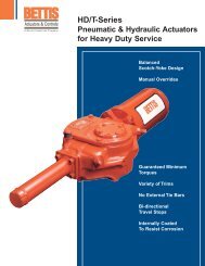
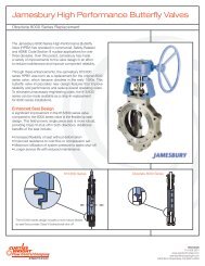
Robotarm II G-<strong>Series</strong>Pneumatic &HydraulicActuatorsXylan CoatedCylinderWater IngressProtectedDual MountingInterfaceBi-directional TravelAdjustmentJackscrew Option(CBA)Low MaintenanceEconomical
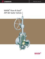
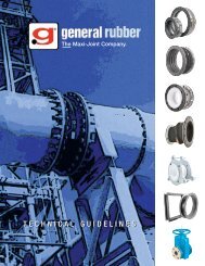
Design and ConstructionIntroductionFor more than 40 years, <strong>Bettis</strong>has combined its ingenuity withhigh quality standards, continuouslypioneering valve actuatortechnology. Beginning with theRobotarm scotch-yoke concept,<strong>Bettis</strong>’ innovations have becometoday’s standards for valve controlin virtually every part of theworld. The company operates inaccordance with ISO 9001 andBS-5750 certifications and maintainsa formal Total Quality Managementprogram to assureproduct excellence. Continuingour innovative tradition, <strong>Bettis</strong>introduces the latest valveautomation advancement…theG-<strong>Series</strong> Robotarm II quarterturnactuator.Product ConceptIn developing the G-<strong>Series</strong>actuators, <strong>Bettis</strong> improved abasic concept — the ReactionBar, by adding our new state-ofthe-artPowr-Swivl, replaceablebearings, highly efficient wearand corrosion resistant coatingsystem, and tension rod compressedspring. This enhanceddesign greatly improves efficiency,reduces wear andextends the actuator’s life. Thecombining of these technologies,enhancements, and superiorquality control techniques producedan assembly whichbecame the heart of our newextended service actuators —the G-<strong>Series</strong>.AdvantagesThe G-<strong>Series</strong> actuators providea unique, highly reliable meansof operating ball, butterfly, orplug valves, as well as louvers,dampers and other 90 degreerotating mechanisms.TandemPneumaticPower ModulePneumatic Power Modulewith Extended TravelStop (shown) or JackscrewPneumaticPowerModuleM-11 Overridefor Hydraulic DAActuatorsCreated with its user’s interestin mind, the G-<strong>Series</strong> actuatorsoffer many significant benefits.Among these are:• Wear Resistance – TheG-<strong>Series</strong> Powr-Swivl piston rodconnection is contained by theguide block, which is supportedby a high strength alloysteel reaction bar treated toprovide a highly corrosion andwear resistant finish. The Powr-Swivl, superior surface finishes,and self-lubricatingbearings maximize the transferof input energy directly to thevalve stem. The tension loadedspring minimizes radial loadson the piston rod, furtherenhancing efficiency.• Service Rated – G-<strong>Series</strong>models are qualified by acceleratedwearage testing. Theactual service life may be predictedbased upon specificapplication parameters andM11 Manual HydraulicPump AssemblyDriveModuleenvironmental conditions.Proper actuator selection,enhanced by proprietary dataanalysis methods, allows optimumperformance and operatingeconomy.• Replaceable Bearings – Lowfriction, permanently lubricated,high performance bearingsprotect sliding androtating components, significantlyextending actuator life.• Five Year Warranty – G-<strong>Series</strong>actuators are backed by theindustry’s strongest materialsand workmanship warranty.• Corrosion Resistance –G-<strong>Series</strong> actuators incorporateprotective internal and externalcoatings, assuring the actuator’sreliable operation in theharshest of environments. Theactuator exhibits excellent corrosionresistance, confirmedby Salt Spray Testing perASTM B117 criteria.2
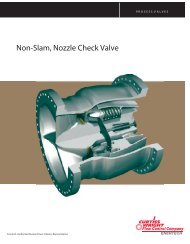
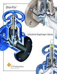
Blind End CapSpringModuleSpring Modulewith IntegralHydraulicOverrideCylinderPneumatic Power Module(Dual Cylinder Configuration)Construction features preventwater ingress, allowing G-<strong>Series</strong> actuators to meet IP 66and IP 67M specifications andsevere high pressure waterdeluge test.• Safety – The G-<strong>Series</strong> facilitatessafe installation andremoval of the spring module.It incorporates <strong>Bettis</strong>’ Tension-Lok (patent pending) whichallows for the removal of thespring module in a manner thateliminates accidental releaseof the spring force. Each moduleis tagged with detailedproduct information, minimizingthe potential for incorrectinstallation, operation, or misapplicationof a reconfiguredactuator.• Versatility – The ease of interchangingthe power andspring modules allows quickreversal of the “fail-safe” mode,while providing for the additionExtended Travel Stop(shown) or JackscrewSpring Module with ExtendedTravel Stop ModuleG-Ride Manual GearOverride for G4 & G5Hydraulic Power Module orM11 Override Cylinder for DAPneumatic ActuatorsNote: The above graphic does not necessarily depict all modular orientations.Consult Factory for certified dimensional drawings.of overrides, accessories andother modules. For instance, aG-<strong>Series</strong> actuator may be easilyaltered from a single-actingto double-acting power cylinderconfiguration, and/or ahydraulic manual override maybe added after the actuatorhas been installed.• True Modular Design – TheG-<strong>Series</strong> versatility is punctuatedby field serviceable modules.The available modulesinclude the drive, power, springand override. These modulesare removable, serviceable andinterchangeable without removingthe actuator from the valve.This procedure does not requirespecial tools or disassembly ofany module. This unique featurereduces required plant shutdowntime for service. Modulesmay be replaced as an assemblyor serviced at your maintenancefacility.• Efficient Modular Inventory –All modules may be purchasedseparately or in anycombination. This featureallows reduced parts andspares inventory at the distributionfacility, while substantiallyincreasing theavailability of different modelconfigurations.• NAMUR – The shaft drivenaccessory interface conformsto the NAMUR standard andis identical on all G-<strong>Series</strong>actuators, allowing for standardizationof accessorymounting hardware andinstallation practices.• MSS or ISO Valve MountingThe G-<strong>Series</strong> valve interfacemeets the dimensionalrequirements of MSS SP-101or ISO 5211 defined for eachtorque range.• Compact – The G-<strong>Series</strong>design optimizes the center ofgravity location, is significantlylighter, and requiresless space than other actuatorsof equal or lesser torqueoutput.• Operating Ranges – G-<strong>Series</strong>double-acting actuators produceguaranteed torque outputsfrom 12,581 lb-in. (1420Nm) to 6,000,000 lb-in.(678,000 Nm). The springreturnunits produce springtorques in excess of 3,000,000lb-in. (339,000 Nm).G-<strong>Series</strong> actuators are suitablefor continuous operationat pneumatic pressures rangingfrom 40 to 200 PSIG (3 to14 BAR), hydraulic pressuresup to 5000 PSIG (345 BAR).Standard temperature range is-20°F to +200°F (-29°C to+93°C). Optional temperatureranges, as defined in item 37of the Specification page,extend the range to -50°F or to+350°F (-46°C or to +177° C).3
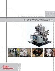
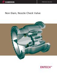
Design and Construction1234567FeaturesTension-Lok <strong>Bettis</strong>’ Tension-Lokpositively locks in place the springmodule while under load. Thismechanism prevents spring moduledetachment from the drivemodule prior to depressurization,extension of the spring to a safecondition, and unseating the Tension-Lokmechanism.Powr-Swivl. The PowrSwivlconnects the piston rod and theguide block, compensating forside load deflection, thus reducingwear on the rod, bearings andseals. Not available on G1 models.Acculine Shaft Drive. The <strong>Bettis</strong>Acculine Shaft Drive assures apositive yoke seal, maintainsaccurate alignment, and eliminatesaccessory shaft side loads.The Acculine Shaft Drive preventsaccidental disengagement of criticalsignal devices or controls,provides visual indication, andhelps maintain the integrity ofhazardous area classifieddevices.NAMUR. The G-<strong>Series</strong> actuator iscompatible with a wide range ofcontrol and signal generatingdevices. The NAMUR mountingconfiguration allows standardizationof mounting hardware forshaft driven accessories.Replaceable Bearings. Replaceablebearings protect sliding androtating components, and are suitablefor either dry or lubricatedworking conditions.Guide Block Thrust Bushing.The Guide Block Thrust Bushingaligns the guide block within theyoke arms to enhance the Powr-Swivl function.Yoke Pin Thrust Bar. The yokepin axial movement is preventedby a non-metallic thrust bartransferring axial loads directlyto the drive module case.1611ACTUATORHOUSINGHOUSINGVENT/CHECKVALVEVENT/CHECKBreatherMSS & ISOCENTERING RING(OPTIONAL)14Dual Internal Tie Bars15Pressure PortOptional Overrides.* The internallymounted hydraulic overridecylinder module for spring-returnactuators, does not increase theoverall length of the actuator.This design positively separatespower and override fluids.Optional features include speedcontrols, by-pass for high speedoperation, special trims, andauto disengage by pilot signal orpower gas.YOKE8 94NAMURBi-directional Travel Stops133Vent-ChecksAcculineShaft Drive57Yoke PinThrust BarReplaceable Bearings12Spring Module. The springs inthe G-<strong>Series</strong> actuators areguided by self-lubricating alignmentbearings. The spring moduleis fully enclosed, andincorporates the Tension-Lokmechanism, preventing potentialinjury to operating personnel ordamage to equipment. Corrosionresistant coatings and seal weldingprotect the spring modulecomponents from the harshest ofenvironments.2 Power-SwivlMSS or ISO ActuatValve Interface4*See page 8 for jackscrew and manual/gear override
or/10Lifting Eyes6Guide BlockThrust Bushing9SpringModuleREACTION BAR1Tension-Lok8Optional OverridesGUIDE BLOCKLOCKEDUN-LOCKED131415stem. A female drive, with fulllength keyed connection, allowsfor mounting the actuator to thevalve in a variety of orientations,when specified.Vent-Checks. G-<strong>Series</strong> actuatorsincorporate two individual drivemodule vent-checks that releaseoverpressure and seal to preventdust, corrosive atmospheres andwater ingress. The lower vent passageisolates valve stem leakageand provides a means to attachfugitive emissions monitoringdevices.Pressure Port. The inboardpressure port location minimizesexposure of supply tubing,thus reducing the opportunityfor mechanical damage onspring-return units. Pneumaticand hydraulic units have NPTports. Consult factory foroptions.Bi-directional Travel Stops. Thebi-directional travel stops are anintegral part of the actuator allowing80° to 100° total travel adjustment.Cylinder mounted extendedtravel stops are optional.POWR - SWIVL(S)1011Lifting Eyes. G4 and largeractuators are equipped withintegral lifting eyes for safe handlingof the actuator during shipping,installation or removal.Eight lifting eyes allow for safelylifting the actuator in all threemajor planes.Breather. G-<strong>Series</strong> actuatorsincorporate a 316 stainlesssteel, normally closed cylinderbreather that allows pressure12equalization to atmospheric conditionsduring operation. Thebreather seals out the environment,meeting IP67M and acceptancecriteria for severe highpressure water deluge test.MSS or ISO Actuator/ ValveInterface. The G-<strong>Series</strong>actuator/valve interface may beprovided with an optional centeringring, assuring accurate alignmentof the output drive and valve16Dual Internal Tie Bars. The pneumaticpower modules feature internalhigh strength alloy steel tiebars. The internal tie bars are protectedfrom corrosion and physicaldamage while also centering thepiston in the cylinder bore thuspreventing metal-to-metal contact.5
Typical SpecificationsThe following information is recommendedas a guide to develop acomprehensive, performance orientedpneumatic and hydraulicactuator and control specification.<strong>Bettis</strong>’ G-<strong>Series</strong> actuators meet orexceed all requirements outlinedbelow.PurposeTo define a pneumatically orhydraulically powered actuatorsuitable for the operation of ball,butterfly, or plug valves, louvers,dampers, and other 90° rotatingmechanisms.1. The actuator shall be competitivelypriced, reliable,scheduled maintenancefree, fully resistant to environmental,power gas, andload conditions.2. The actuator shall bedesigned to facilitate ease ofinstallation and serviceability.The actuator shall incorporatea true modular design to simplifyfield service, interchangeabilityof the powerand spring modules, and theaddition of manual overridesand accessories. Each primaryactuator module shallbe permanently identifiedand documented to allowaccurate identification ofcomponents and applicationcriteria.3. The actuator shall meet allapplicable design codes,safety restrictions, and applicationpractices includingSI 1029 regulations andIP 67M type testing.4. The power and spring modulesshall be rigidly attachedby external bolting to thedrive module and accuratelyaligned by a piloted interface.The attachment shall notrequire special tools, disassembly,or disturbance ofseals of any module.5. The pneumatic power moduleshall be constructed with dualinternal tie bars of highstrength alloy steel protectedby corrosion and wear resistantcoatings. Power modulesshall be constructed to allowpressure testing independentof the drive module.6. The reaction bar shall besized to minimize lateraldeflection, be corrosion andwear protected by a chemicalbath surface conversionprocess applied in accordancewith <strong>Bettis</strong>’ ESC 20specification, and shallexhibit a minimum surfacehardness of 60 Rc.7. The actuator shall be produced,service rated andauditable to a written QualityAssurance Program complyingwith ISO 9001, 10CFR50Appendix B, CSA Z-299, andwhen specified, DIN 500493.1.b.8. All actuators and modulesshall meet acceptance criteriadefined by <strong>Bettis</strong>’ ES-6 testspecification latest revision orequivalent prior to shipment.9. The actuator shall be fullyqualified for the purposesintended by passing allaspects of select industryperformance and design testcriteria.10. The actuator shall exhibitexcellent corrosion resistanceconfirmed by Salt Spray Testingper ASTM B117.11. The valve drive interfaceshall meet the applicablerequirements of MSS SP-101or ISO 5211 Standards. Acentering ring shall be providedto assure geometricallyaccurate valve/actuatoralignment, when specified.12. The actuator shall be providedwith a full length keyedfemale drive connection suitablefor mounting in multipleorientations, as specified.13. The actuator shall be servicerated based upon load andapplication parameters,auditable to acceleratedwearage test data.14. Integral lifting eyes shall beprovided on units weighing800 pounds or more to facilitatesafe shipping, handling,installation, and removal of theactuator. Eight lifting eyes, suitablefor safely lifting the actuatorin all three major planes,shall be sufficiently sized andlocated to accept appropriatelyrated lifting devices.15. All external bolting shall beinstalled in blind tappedholes to protect the threadsand positively prevent wateringress as defined by therequirements of IP 66 andIP 67M. Sheet or fibrous gasketsshall not be used forpressure or environmentalseals.16. The NAMUR mounting configurationshall be incorporatedfor the attachment of allshaft driven accessories. Theattachment configurationshall be identical for all actuatormodels and shall providevisual positionindication.17. Accessory drive shaft shallbe bearing centered, withrespect to the mountingpattern and isolated fromany axial or radial yokemovements.18. All shaft driven control andsignal devices shall be protectedfrom mechanical damageby a bearing centeredshaft drive meeting NAMURdimensional specifications.Device attachment shall beidentical and interchangeablebetween all models.19. The spring preload shall applya compression force to positivelyretain the spring and6
drive module interface underall operating conditions.20. Safe spring module installation/removalshall be inherentwithin the spring attachmentdesign and shall not requirespecial tools. The lockingmechanism shall be selfengagingand highly visibleduring assembly, assuringthat the lock position isattained. The mechanismshall positively disallowspring module detachmentwhile in a loaded condition,preventing sudden or violentrelease of the spring module.21. The spring module shall befully enclosed to eliminatepersonnel hazards, o-ringsealed and welded to protectall components from harshenvironmental conditions.22. The spring and springretainer shall be self-centeredand bearing guidedwithin the spring module. Thespring retainer shall transferaxial tension and limit buckling,minimizing metal-tometalcontact between thespring and barrel.23. All module interfaces shallinclude a precision machinepilot to ensure accuratealignment.24. The spring-return actuatorshall utilize an inherentlyguided tension rod to energizethe compression spring eliminatingthe need for tie bars.25. Each actuator shall be fittedwith two (2) 316 stainlesssteel, normally closed ventchecksto protect the drivemodule from overpressure.The single-acting actuatorpower module shall incorporatea 316 stainless steel bidirectionalbreather/vent.Each actuator shall be appropriatelysealed in a mannermeeting IP 66, or IP 67M, andhigh pressure deluge testwithout water ingress.26. The piston rod to guide blockconnection shall compensatefor angular and lateral deflectioncaused by side loads.27. The piston rod shall bedetachable from the drivemodule without the need ofspecial tools or module disassembly.28. Replaceable bearings shallexhibit documented,extended wear capabilitiesand shall be suitable for dryor lubricated working conditions.Sliding and rotating ferrousmetal surfaces shall beprotected by suitable bearingsto control wear.29. Durable wear and corrosionresistant ferrous metal conversioncoatings shall aidextended wearage resistanceand rated torque output aspublished when completelyvoid of supplemental petroleumor synthetic grease oroil. Metallic coating of pressurecontaining and loadbearing surfaces which canbe scratched, cracked, orpeeled allowing ferrous metalor sharp seal cutting edges tobe exposed are prohibited.30. All contact surfaces of theguide block assembly shallincorporate replaceable bearingsand a rigid rotating pintorque transfer mechanism,reducing wear caused by pindeflection.31. The yoke pin shall rotate in aself-lubricating bearing toeliminate sliding friction in theyoke slots and shall beretained by stationary nonmetallicthrust bars to reducewear and extend the servicelife of the actuator.32. The manufacturer shall providea five-year materials andworkmanship warranty.33. All actuator pressure portsshall be appropriately markedto identify proper connectionof control components.34. Bi-directional travel stopsshall be included as an integralpart of the actuatorallowing 80° to100° totaltravel adjustment.35. For spring-return models,the optional, single-actinghydraulic override cylindershall be installed inside thespring module and shall notincrease the length of theactuator. The cylinder shallbe pre-assembled andtested prior to installation.36. The optional hydraulic manualoverride module shallincorporate a positive displacementpiston pump,directional control valve, fluidreservoir, level indicator, andpressure relief. Optionalenhancements shall includebi-directional speed controls,by-pass for high speed operation,special trims, and autodisengage by pilot signal orpower gas pressure.37. The construction of the actuatorshall be suitable for continuousexposure to ambienttemperatures of -20°F to+200°F (-29°C to +93°C).Optional low temperature trimis available, allowing continuousoperation at -50°F to+180°F (-46°C to +82°C) forpneumatic units and -50°F to+200°F (-46°C to +93°C) forhydraulic units. Optional hightemperature trim is suitablefor continuous exposure toambient temperaturesbetween 0°F to +350°F (-18°Cto +177°C).38. Standard valve position stopsshall provide +/-5° adjustmentand be capable ofstalling the actuator at themaximum torque output. Fullrange extended travel stopsshall be provided, whenspecified. 7
OPTIONAL OVERRIDES<strong>Bettis</strong> offers several overrides for G-<strong>Series</strong> model, they include:Jackscrew – manual override for G-1, G-2, and G3 models with or withouthandwheel.G-Ride – gear override available on G-4 and G-5 models. All overrides have avariety of options available including proximity switches and lock out features.BETTISYSTEMS<strong>Bettis</strong> has pre-engineered and documented a series of commonly requiredcontrol systems. These approved systems utilize standard components,reduce lead times, and simplify purchasing, installation and start-up. Pleaseconsult the factory for additional information.BETTIS TECHNICAL DATA<strong>Brochure</strong> & WebsiteFor torque outputs,sizing information,displacements, weightsand dimensional drawings onG-<strong>Series</strong>, see <strong>Bettis</strong>’ TechnicalData <strong>Brochure</strong> or visit our websiteat www.bettis.com.<strong>Bettis</strong> USAP.O. Box 508Waller, TX 77484 U.S.A.T 281-463-5100F 281-463-5103www.EmersonProcess.comInfo.<strong>Bettis</strong>@EmersonProcess.com<strong>Bettis</strong> UK Ltd.3 Furze Court114 Wickham Rd.Fareham, Hampshire PO 16 7SHT 44-1329-848-900F 44-1329-848-901<strong>Bettis</strong> Canada Ltd.4112-91 A StreetEdmonton, Alberta T6E 5V2CanadaT 780-450-3600F 780-450-1400<strong>Bettis</strong> France:30/36 Allee du Plateau93250 VillemombleFranceT 331-48-122610F 331-48-122619<strong>Bettis</strong> Int’l Sales Office:Calgary, CanadaRheinberg, GermanyNew Bombay, IndiaSingaporeImportant: Due to Emerson’s continuing commitment to engineeredproduct advancement, data presented herein is subject to change.BETTIS BULLETIN # 35.00-1 REV: 1/02© 2002 Emerson. All rights reserved. 5M/1-02