Maximizing Filtration With Rosedale's Unique âY ... - Filtration News
Maximizing Filtration With Rosedale's Unique âY ... - Filtration News
Maximizing Filtration With Rosedale's Unique âY ... - Filtration News

Create successful ePaper yourself
Turn your PDF publications into a flip-book with our unique Google optimized e-Paper software.
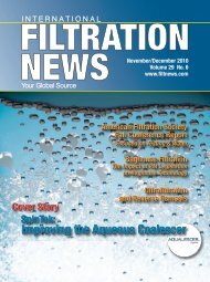
I N T E R N A T I O N A LFILTRATIONNEWSYour Global SourceMay/June 2012Volume 31 No. 3www.filtnews.comSpecial Reports:- High Level Presentations atWorld <strong>Filtration</strong> Congress, Austria- Metal <strong>Filtration</strong>- Testing and Instrumentation<strong>Maximizing</strong> <strong>Filtration</strong><strong>With</strong> Rosedale’s<strong>Unique</strong> “Y” Pleat Cartridges
Editorial Advisory BoardEditorial Board ChairmanEdward C. Gregor,ChairmanE.C. Gregor & Assoc. LLCTel: 1 704 442 1940Fax: 1 704 442 1778ecg@egregor.comM&A, <strong>Filtration</strong> MediaHaluk Alper, PresidentMyCelx Technologies Corp.Tel: 770.534.3118Fax: 770.534.3117alper@mycelx.comOil Removal – Water and AirPeter S. Cartwright, PECartwright Consulting Co.cartwrightconsul@cs.comMembranes, RO,UltrafiltrationWu ChenThe Dow Chemical CompanyTel: 1 979 238 9943wuchen@dow.comProcess <strong>Filtration</strong> (liquid/gas)Equipment and MediaPeter R. Johnston, PETel/Fax: 1 919 942 9092ddandp3@aol.comTest proceduresJim JosephJoseph MarketingTel/Fax: 1 757 565 1549josephmarketing@verizon.netCoolant <strong>Filtration</strong>Dr. Ernest MayerDuPont Co.Tel: 1 302 368 0021Fax: 1 302 368 1474ernest.mayer@usa.dupont.comGeneral Solid/Liquid Separationsin All AreasRobert W. McilvaineTel: 1 847 272 0010Fax: 1 847 272 9673mcilvaine@mcilvainecompany.comwww.mcilvainecompany.comMkt. Research & Tech. AnalysisHenry Nowicki, Ph.D. MBATel: 1 724 457 6576Fax: 1 724 457 1214Henry@pacslabs.comwww.pacslabs.comActivated Carbons Testing,R&D, Consulting, TrainingBrandon Ost, CEO<strong>Filtration</strong> GroupHigh Purity Prod. Div.Tel: 1 630 723 2900bost@filtrationgroup.comAir Filters, Pharmaceuticaland Micro-ElectronicGregg PoppeThe Dow Chemical CompanyTel: 1 952 897 4317Fax: 1 942 835 4996poppeg@dow.comIndustrial Water, Power,and Membrane TechnologyDr. Graham RidealWhitehouse Scientific Ltd.Tel: +44 1244 33 26 26Fax: +44 1244 33 50 98rideal@whitehousescientific.comFilter and Media ValidationAndy RosolGlobal <strong>Filtration</strong> Products Mgr.FLSmidth Mineralsandy.rosol@flsmidth.comTel: 1800 826 6461/1 801 526 2005Precoat/Bodyfeed Filter AidsClint ScobleFilter Media Services, LLCOffice: 1 513 528 0172Fax: 1 513 624 6993cscoble@filtermediaservices.comFabric Filters , Filter Media,Baghouse MaintenanceTony ShucoskyPall MicroelectronicsTel: 1 410 252-0800Fax: 1 410 252-6027tony_shucosky@pall.comCartridges, Filter Media,MembranesMark VanoverBayOne UrethaneSystems LLCMarketing ManagerTel: 1- 314-591-1792Email:mark.vanover@bayone.comPolyurethane SystemsScott P. Yaeger<strong>Filtration</strong> and SeparationTechnology LLCTel/Fax: 219-324-3786Mobile: 805-377-5082spyaeger@msn.comMembranes, New Techn.Dr. Bob BaumannAdvisory BoardMember Emerituswww.filtnews.com • June 2012 • 3
Industry | <strong>News</strong>High Level Presentations atWorld <strong>Filtration</strong> Congress, AustriaBy Geoff Fisher, European EditorMesse Congress Graz, location of the 11th World <strong>Filtration</strong> Congress & Exhibition (WFC11) held in April.The 11th World <strong>Filtration</strong>Congress & Exhibition(WFC11), held in the delightfulcity of Graz, Austria, fromApril 16-20, 2012, brought togetherresearchers and developers with manufacturersand users of separationequipment with the aim of speedingup the process of finding improved solutionsfor current and future separationproblems.A UNESCO World Heritage Site, EuropeanCapital of Culture 2003 and thesecond largest city in Austria with250,000 inhabitants, Graz is surroundedby mountains with the riverMur running through the heart of thecity. The Mediterranean atmosphere ofthe picturesque old town, with its Renaissance,Gothic and Baroque styles,provides a striking contrast to someo u t s t a n d i n gultra-modernarchitecture.Mechanicalparticle separationprocessesplay an indispensablerole innearly all aspectsof Wilhelm Höflingeractivitiesto solve important problems, suchas energy supply, food, water, healthand the environment, noted CongressChairman Professor Wilhelm Höflingerof Vienna University of Technology inhis opening remarks.First organized in Paris, France, in1974, and held every four years since,WFC11 was hosted by the AustrianChemical Society (GÖCH) and attractedsome 740 delegates, accordingto Prof. Höflinger.The five-day event featured approximately320 technical papers from 45countries, of which 95 were poster presentations.The remainder was splitinto three main topics – solid/liquidseparation; aerosol filtration, air filtrationand gas filtration; and membraneprocesses – with lectures held in sevenrooms simultaneously. Other key topicsincluded filter media; testing, instrumentationand control; andsimulation and modeling. Also featuredwere four keynote lectures and a seriesof short courses presented by leadingexperts in the filtration field.In the plenary lecture, Dr. HaraldAnlauf of Karlsruhe Institute of Technology(KIT), Germany, discussed thetechnical development of separation by4 • June 2012 • www.filtnews.commutation andselection. Usingseveral examples,Anlaufdemonstratedthat technicalprogress in thefield of separationtechnology Harald Anlaufcould be comparedin many ways with evolutionarydevelopment in nature. Mutation andselection are mechanisms that can befound not only in biology, but also in atechnological context, he said.For instance, cross-flow membranefiltration and strainers for pre-separationof oversize particles are used in artificialkidneys for haemodialysis,which is an analogue of the baleen of awhale to filter krill from seawater.KEYNOTE LECTURESAmong the keynote lectures, GerhardKasper, also of KIT, noted thatbag house filters have traditionallybeen among the most effective gascleaning methods available with respectto particulate emission levels, aswell as for submicron dust. Key issuesare the cleanability and energy effi-
CongratulationsCongratulations to the AFS on 25 years of excellence.Ahlstrom is a high performance materials company,partnering with leading businesses around the world tohelp them stay ahead.Ahlstrom <strong>Filtration</strong> is setting benchmarks in filtrationmedia and the filtration market: we are a global leader inthe design, development and manufacture of innovativefilter media.Congratulations to AFS on 25 Years of Service fromKeystone <strong>Filtration</strong> Solutions, a leading supplier of filtrationproducts to the water and industrial markets since 1965.Keystone is introducing its Filter Klear® AquaKey productline, which combines the renowned Giant® line of filtrationproducts with innovative UV Technology. AquaKeyjoins a line of products that includes Nano-Key, FilterKlear® filtration solutions, and skidded systems for yourchemical and water sustainability needs. Contact us at1-800-822-1963 Visit: www.KeystoneFilter.comQuantachrome Instruments congratulates the AFS on25 years of service to the filtration and separations community.Through its corporate sponsorship program theAFS has brought Quantachrome's name to the attentionof its entire membership, and the AFS annual meetingallows Quantachrome to bring its specialty pore size analyzer,the Porometer 3G, to a live audience. The Porometer3G, the direct descendent of the Coulter Porometer,has revitalized interest in capillary flow porometry sinceits introduction in 2010.Congratulations AFS on 25 years of service!For over 45 years, Zeus has excelled in the developmentof high-performance polymer tubing. Zeus has new innovativemedia products for filtration markets and has developedFiltriq®, nano-fiber processed from PTFE. This product increasesthe efficiency of filter applications through reducedpressure drop while maintaining HEPA or UPLA particle capturerequirements. Zeus also manufactures membranesusing microporous materials like Aeos® ePTFE. Filtriq® &Aeos® ePTFE products will enhance filter applications forpharmaceutical, aggressive chemical filter and air filter applicationsglobally.We are proud to be members of the AFS and congratulatethem on 25 years of educating and training inthe field of filtration and separation. Our personal thanksto the great staff at the AFS, without them the stridesmade in educating the public and private sector about filtrationand separation would not be possible. We wouldlook forward to working with them for another 25 years!For over 60 years Dexmet Corporation has been theglobal innovator of precision expanded metals, foils, andpolymers for Industrial <strong>Filtration</strong> and chemical processing.Many of our products can be found in filters thatserve the automotive, chemical, pharmaceutical, waterpurification, and food & beverage industries. Visit us onlineat www.dexmet.com.Congratulations AFS on your 25th anniversary. It’s theplace all the great minds of filtration can come together.Keep up the great work.The Oberlin Filter Company and its Automatic PressureFilter - The Best Idea in Liquid-Solid Separations for bothsensitive and demanding applications.Filtrate quality down to 1 micron, automatic dry solids discharge.No operator intervention. Food grade and specialalloys available for corrosive duties.Contact Oberlin Filter for a working solution to yourliquid-solid separation problem.Website: www.Oberlinfilter.comAmerican <strong>Filtration</strong> & Separations SocietyWeb: www.afssociety.org
Industry | <strong>News</strong>Lenzing Technik highlighted the RWFautomatic backwash filter that canreplace one-way filters.quences and the impact of leaks.His discussion revolved around therelationship between dust concentrationand the total amount of dust (perunit filter area) emitted during a cycle,and the consequences of these findingsfor minimizing dust emissions in thecontext of industrial operating environments.Meanwhile, Kuo-Lun Tung ofChung Yuan University, Taiwan, offereda new geomimetic approach to the designof novel inorganic membranes.(Geomimicry seeks to replicate knowngeophysical forces.) He said a noveltechnique that assists the atmosphericplasma spray (APS) coating method tofabricate a macroporous Al 2 O 3 membrane,with pore sizes ranging fromaround 0.2-0.3 µm, has been developedat the University’s R&D Center forMembrane Technology.Ahlstrom has developed advanced filter media for a variety of industries andapplications.ciency of such devices. Emission specificationsfound in requests for proposals(RFPs) have becomeincreasingly tighter, however, withtypical levels approaching 1 mg/m 3 .Moreover, public environmentalconcerns about ambient “fine dust” andthe advent of particle size specific emissioncriteria, such as PM10 or PM2.5,have added further pressure to investigateemission mechanisms and behaviorof cleanable filters.Kasper described an analysis ofemission data for various filter-operatingscenarios, including a comparisonof agglomerating and non-agglomeratingdust, operation at different raw gasconcentrations, different ageing se-SMART APPROACHDr. Karsten Keller of Solae/DuPont,USA, introduced the SMART approachfor separation challenges for biotechnology.This systematic methodologyinvolves:• Selective separation technology• Managing the product properties• Advanced mechanical separationtechnology• Reorganizing the separation forces• Treatment with enzymesExamples of SMART include membranetechnology, magnetic separation,enzyme treatment and additional approaches.Some of these are in the earlyresearch stage, while others are close toimplementation, said Dr. Keller.Andreas Wiegmann of the FraunhoferInstitut für Techno- undWirtschaftsmathematik, Germany, describedmodeling and simulation of filtrationprocesses from a practitioner’soverview.He showed how detailed three-dimensionalimages and models of filtermedia, filtration process models, computationalfluid dynamics and statisticscould provide valuable guidelines forfiltration from the practical viewpointand deep new insights from the academicperspective.6 • June 2012 • www.filtnews.com
Industry | <strong>News</strong>Filter media from Irema-Filter are widely used in HVAC applications.A highlight of WFC11 was an extensiveexhibition area where approximately100 international suppliers offiltration and separation equipment,engineering companies, manufacturersof related measurement instrumentsand test laboratories featured the latestinnovations and technology. Most ofthe exhibitors said they were more thansatisfied with the amount of visitor trafficand contacts made with the internationalfiltration industry.BLUE ENERGYFujifilm Manufacturing Europehighlighted its membranes for reverseelectro-dialysis (RED) technology forthe generation of “blue energy” usingadjacent fresh and salt water.Fujifilm ion exchange membranes willbe used in a 50 kW pilot plant installationto be built this year on the Afsluitdijk, amajor causeway in the Netherlands. Thisis the basis of a four-year project designedto make the sustainable generation of energyeconomically and technically feasible,said Meindert Slagt, businessdevelopment manager.Meanwhile, Ahlstrom <strong>Filtration</strong>launched the XAIR range of automotiveand heavy-duty air filter media,which is said to provide exceptionalefficiency in soot filtration and dustholding capacity compared with standardproducts.Lenzing Technik of Austria highlightedthe RWF automatic backwashfilter that can replace one-way filters.This technology allows for very fine filtrationdown to 1 µm with a largeamount of solid content and highthroughput.Irema-Filter of Germany presentedits broad product range of filtrationAnja-Michen MüllerK.C. Pereramedia for industrial and automotive applications,and now also for liquid filtrationapplications, according toAnja-Michen Müller, sales and marketingmanager. New innovative media are8 • June 2012 • www.filtnews.comavailable for heating, ventilation andair-conditioning (HVAC), cabin air, engineair, oil filtration, hydraulic applicationsand fuel filtration.Sandler of Germany also featured itswide range of carded and meltblownnonwovens, as well as multilayer composites,for use as filter media for suchapplications as dust filtration, HVAC,air and cabin filtration, vacuum cleanerbags, extractor hoods, climate controlfilters in electric appliances and filtermats for spray painting facilities or liquidfiltration.UK-based Eurocarb Products is theEuropean operations center for SriLanka-headquartered Haycarb, a leadingglobal manufacturer of coconutshell activated carbon. Eurocarb providessolutions for the removal of gasand vapor contaminants from air; thecompany’s activated carbons are alsoused in critical water filtration applications.It is currently investigatingthe potential applications in the biogasindustry, revealed Market DevelopmentManager K.C. Perera.The 12th World <strong>Filtration</strong> Congress& Exhibition (WFC12) will be held inTaipei, Taiwan, in spring 2016.FN
Cover Story | Rosedale <strong>Filtration</strong><strong>Maximizing</strong> <strong>Filtration</strong> <strong>With</strong>High-Capacity “Y” Pleated CartridgesBy Dan MoroskyDepending on the application,high-capacity pleated cartridgescan have many advantages:one high-capacity pleatedcartridge can replace as many as 22string-wound cartridges, disposalcosts are lower, and a high surfaceareacartridge may only have to bechanged out two or three times a yearcompared to possible weekly changeouts when using standard cartridges.Cartridges can be used in verticalor horizontal housings. If no downtimecan be tolerated, parallel filters(sized to handle the total flow rateof the processing line or the effluentline) can be used.High capacity cartridges are madefrom several types of filter media andpore sizes in order to maximize dirtholdingcapacity. Availability of highsurface area, materials of construction,and filter efficiency, the high capacitycartridge can handle a wide variety offluids at various temperatures.Absolute-rated filter cartridgesoffer maximum dirt holding capacitycoupled with micron retention ratingsto 0.5 at 99.98% efficiency.Elements are manufactured in aunique “Y” pleat arrangement thatoptimizes its physical size and maximizeseffective surface area. A lowfluid flux rate maximizes dirt containment.This means element life isextended and productivity is increased,resulting in fewer cartridgechange-outs, less labor, and lower replacementcosts.DESIGN DETAILSThis design uses only the highestquality materials and most advancedmanufacturing processes. The endcaps are heat sealed for high efficiencyperformance. The o-ring sealinsures sealing and eliminates bypass.CARTRIDGE SIZESCartridges are designed to fit allstandard housings, and multi-housings.Typical cartridge size specificationsand flow rates can be seen incharts 1, 2 and 3 on the next page.For more information contact:Rosedale <strong>Filtration</strong> Products3730 W. Liberty RoadAnn Arbor, MI 48103Tel: 1-800-821-53731-734-665-8201Fax: 1-734-665-2214Email: filters@rosedaleproducts.comWebsite: www.rosedaleproducts.comFNThe Importance of Absolute Efficiency RatingConsider a filter with an absolute efficiency rating of99.98% at 2 microns. A 99.98% efficiency equates to a betaratio of 5,000. In contrast, a 99% efficiency filter has a betaratio of 100. This means that a beta 5,000 filter will only pass1 particle in 5,000 greater than 2 microns. A beta 100 filterwill pass 1 in 100 particles greater than 2 microns.The Beta Ratio (ß) at a given particle size can be correlatedto the filter efficiency at that particle size according tothe following formula:Filter Efficiency (%) = [(b-1)/b] x 100%Beta Ratio (ß) 100 1,000 5,000Filter Efficiency (%) 99.00 99.90 99.98Each filter element will have a different Beta Ratio forevery specified particle size. The determination of a varietyof Beta values for the same filter provides a filter efficiencyprofile commonly referred to as a Beta Curve.FN10 • June 2012 • www.filtnews.com
The “Y” pleatmaximizes effectivesurface area.Chart 1:• 100 sq. ft. of surface area maximum• 20 lbs. (approx.) of dirt carrying capacity• Rated 0.5 micron to 70 micron@ ß5000 or 99.98% efficiency• Flow rates to 100 gpm.• 6.25-inch diameter and 35-inch lengthChart 2:• 400 sq. ft. of surface area maximum• 100 lbs. (approx.) of dirt carrying capacity• Rated 0.5 micron to 70 micron@ ß5000 or 99.98% efficiency• Flow rates to 800 gpm• 13-inch diameter and 40-inch lengthChart 3:• 1150 sq. ft. of surface area maximum• 250 lbs. (approx.) of dirt carrying capacity• Rated 0.5 micron to 70 micron@ ß5000 or 99.98% efficiency• Flow rates to 800 gpm• 20-inch diameter and 40-inch lengthwww.filtnews.com • June 2012 • 11
Baghouse & Dust CollectionSelecting the Proper FilterMedia for Dust Collection SystemBy Clint Scoble, President and Managing Director, Testori USA, Inc.Part 2 of a 2-part series: The Advanced Course in Media SelectionPreviously, “The Basic” coursecovered four basic questions toask when selecting the properfilter media for a dust collecting system.After determining the continuous gasstream temperature, the design of thecollector, the possible presence of waterand the potential for any chemical reaction,media selection can be narroweddown to correct fiber and correct fabricdesign for a dust collector bag. The AdvancedCourse in Media Selection – understandingand analysis – is requiredto optimize performance of the selectedfilter media. Since the predominant collectordesign today is the pulsejet collector,Course 2 will focus on needledfelts as the primary filter medium sincethere are more variables, options anddesign opportunities.Understanding and anticipating dustcharacteristics is the heart of this nextlevel of analysis. Also requiring considerationare the effects of moisture orhydrocarbons on the dust, the potentialfor static buildup and the potential forsparks or live particles.Basic dust characteristics, onceknown, will influence the felt fiber sizeand distribution as well as cake sidesurface design, scrim type and specificationsand, finally, chemical finishesand surface treatments. Major dustcharacteristic questions are:Question #1: Is the dust free flowingor does it tend to agglomerate?Question #2: What is the particle size,shape and distribution?Question #3: Is the dust abrasive?Question #4: Is the dust fibrous?These four questions, parts of whichcan be scientifically determined andparts of which are more subjective,gives “the rest of the story” for choosingthe optimum media. The singlemost important issue above is whetherthe dust is free flowing or whether itagglomerates because that determineswhether the media must be efficient12 • June 2012 • www.filtnews.comenough to separate a small particle,which does not normally form a cohesivefilter cake or whether the focus hasto be on dust cake release because thedust will be difficult to pulse off thecollecting surface.There are multiple options availableto deal with fine dust and free flowingparticles. Depending on the severity orcomplexity of the problem, felt mediaoptions include:1) Dual density felt with finer fiberslayered on the “dirty” or cake sideof the media.2) Microdenier fiber felts where fibers1 micron or smaller are eitherlayered or blended with fine fiberson the collecting side of the media.3) Composite fiber felts where highsurface area fibers (P84® forexample) are layered or blendedwith fine fibers on the cake side.4) Urethane surface coating, whichconsists of thin, open cell layers ofpolymer on a suitable substrate.5) PTFE membrane laminated to asuitable substrate.Note: High efficiency felts (DualDensity, micro-denier and compositefelts) normally have a singed cake sidesurface to allow optimum clean-abilityof a free flowing dust when pulsing.These many options provide theOEM, the bag converter and the enduser with many suitable options fordealing with difficult dust and meetingcurrent PM and emission standards.Particle size analysis (PSA) and dustevolution will indicate to the experiencedtechnician, which medium pro-
Xinxiang Tiancheng AviationPurification Equipments Co. Ltd.For airplaneFor special vehicleFor ultrafilterFor coal machineryFor dustcollectorof cementindustryFor fluid cleaning systemOur company specializes in designing & manufacturing and supplying many kinds of filters,complete filtrating equipments and their elements with different materials according to yourdrawings or new & old samples.Xinxiang Tiancheng Aviation Purification Equipments Co. Ltd.No. 1, Chuanye Road, Dvelopment Area, Xinxiang City 453003, HenanP.R. ChinaContact Person in China: Mr. Li MinghaoTel: +86-13673735086 Fax: +86-373-3520026 Website: www.tchkjh.comE-mail: lmhao116@yahoo.com.cn • tchkjh@yahoo.com.cnsunny0505@tchkjh.com • niushaohui@hotmail.comContact Person in USA: Mr Liu ShengyuanTel: 4015881868 • liushengyuan@tchkjh.com
Baghouse & Dust CollectionWater droplets on the surface of an oil and water repellent treated feltvides the best combination of efficiency,pressure drop, bag life and long termcost.On the other side of the spectrum isdust, which readily agglomerates ordust with moisture or hydrocarbons inthe gas stream. In this situation, filtermedia efficiency is generally not anissue, regardless of particle size. Here,the dust literally collects itself and longbag life depends on the ability of themedium to release the filter cake effectivelyand thoroughly. One must alsoavoid sticky solids penetrating thedepth of the felt and becoming lodgedin the media ultimately causing the feltto blind prematurely.In the case of agglomerating orsticky dusts, the media options are:1) Mechanical treatments of themedia to minimize or eliminatesurface fibers.2) Chemical treatments offluorocarbons, PTFE orurethane.3) Membrane laminates14 • June 2012 • www.filtnews.comThe mechanical treatment option isvery basic and adds relatively little costto the medium or finished bag. Typicalmechanical treatments are singeing ofthe cake side surface fibers in non-thermoplasticmaterials such as acrylic,aramid and polyimide fibers and glazing(melting/smoothing process) ofthermoplastic fibers such as polypropylene,polyester and PPS. In both cases,the objective is to provide a sticky dustwith limited opportunity to attach itselfto the fibers, which are present on thesurface of an unfinished felt medium.However, mechanical treatments aregenerally not enough to handle aggressivelyagglomerating solids and, in thatsituation, one turns first to oil andwater repelling chemicals such as fluorocarbonbath treatments. These treatmentsencapsulate each fiber and willactually create a filter felt, which willbead water and oil. T he combination ofmechanical surface and durable chemicalbath treatment will significantly extendthe life of a dust collector bagwhen moisture, fats or oils are presentin the gas stream or product itself.PTFE bath treatments, although notrepellent, do increase the anti-adhesioncharacteristic of a fiber and are used inmany applications, especially in utilityboiler baghouses. Lastly, membranelaminates work well with releasing wetdust, but caution must be taken toavoid using membranes when hydrocarbonsor natural fats/oils are present.Regarding abrasive dust, the most
The deadline for the buyers’ guide isfast approaching. Call or email beforeJune 1st. to get a discount on your entry.Tel: 1-248-347-3486Email: joan@filtnews.com2012June 2012 • www.filtnews.com • 15See us at American <strong>Filtration</strong> Conference
Baghouse & Dust CollectionStatic Dissipating Polyester Feltcommon solution is to treat the media– whether a synthetic fiber or a wovenfabric – with a heavy silicone solution.The key is to deposit enough siliconeso that, after the media is dried (orcured), each fiber is fully coated. Foreffective abrasion resistance, the minimallyacceptable amount of silicone foreffective performance (measured afterdrying) is 4-5 percent of the media’sbasis weight. When the silicone coatingis adequate, it tends to deflect dust particles’direct abrasive contact on themedia surface. As particles penetratethe media, the silicone acts as a lubricantto protect the fibers inside themedia from abrasive wear.Fibrous dusts present a unique situationin a baghouse because that problemmay create significant downtime ifnot addressed early in the media selectionprocess. The fibrous dust cakeformed on the filter bags can eventuallybridge between bags and between thebags and the collector wall, packingthese areas so densely that the only wayto clean out the baghouse is to go insideand remove the fibrous dust cakeby hand. Typical fibrous dusts includedust from coarsely sawn wood, fiberglass,diaper components, andpolypropylene-polyethylene streamers.A few filter media that can mitigate fibrousdust problems include:1) Felt media with a heavy glaze on itsdust-cake side (suitable only formedia with thermoplastic fibers).2) Urethane surface coating, whichconsists of thin, open cell layers ofpolymer.3) PTFE membrane on a suitablesubstrate.In all cases above, the recommendedmedia presents very small openings onthe cake side surface, which limit theability of fibrous dust to attach its tendrilsto the media surface. This, in effect,stops the problem before it starts.Static problems are being addressedtoday in numerous seminars related toplant maintenance and housekeeping.From a filter media perspective, there are16 • June 2012 • www.filtnews.comproducts readily available today, whichmake highly resistive synthetic felts conductiveand allow the end user to knowthat a very high percentage of static,which may build up on a filter bag, can beconducted to ground. Bag and collectordesign are also important here. The pastand more current technologies for manufacturingstatic dissipating filter media are:1) Epitropic (carbonized) fiberblend felts2) Stainless steel fiber blend felts3) Stainless steel scrim supported feltsOf these three, item (3) above is thecurrent technology and employs a wovenscrim in the middle of the felt with alternatingsynthetic and stainless steel yarns,in which the stainless steel yarns arespaced approximately 1/2” - 5/8”/13 - 16mm apart. Current resistivity standardsfor a typical static dissipating media requirethat it not exceed surface resistivityof 10 6 ohm using the DIN 54345/1 - 5 testmethods. In actual testing, most static dissipatingfelts do not exceed 10 4 .
The majority of static dissipating feltsare polyester but there are applications foralmost every generic fiber group. In conjunctionwith other related dust controlprocedures, a static dissipating media willeffectively contribute to a plant’s overallreduction of potential explosion hazards.Lastly, there may be a situationwhere sparks or live particles may bepresent or potentially present. Hot orburning particles can create pinholes inthe media. In the worst case, a hot orburning particle or spark can create abaghouse fire that destroys the filtersand damages the baghouse’s metalstructure and related components.A common way to prevent theseproblems is to install a mechanical orchemical spark- and fire-prevention systeminside the baghouse. Selecting a particularspecialty media or mediatreatment is another approach. Theseoptions include:• Using a flame retardant chemicalfinish on the filter media. This finish isminimally effective and does not preventpinholing.• Switch from a thermoplastic mediafiber, such as polyester or polypropylene,to a higher-temperature fiber thatwill not support combustion or melt,such as aramid or fiberglass.• Use a media with a layer of nonflammablefiber or coating on the dustcakeside.• Use a media with nonflammable,high temperature surface treatment –such as graphite, PTFE, or another similarmaterial – on the dust-cake side.• Use a chemical spark inhibitortreatment, which actually interfereswith the combustion process.If no mechanical or process relatedsolution for sparks or live particles ispossible, the above alternates may improvethe situation.To the first time buyer of bags or adust collector system, the “Basic” and“Advanced” steps may appear to be adaunting task. The key to properly selectingthe correct filter media for a systemis to know and understand threemajor parts of the project:1) Know the process, how it worksand what it produces in gas streamand particulate.2) Know the dust, what it is and howit performs.3) Know the filter media options andsolutions or best features, whichmatch the process and the dust.Carefully considering all of thesefactors and making an informed decisionwill result in a safe, efficient andeffectively performing filter bag anddust collector system.FNFor more information contact:Clint Scoble, Testori USA, Inc.Tel: (Cell) 1-513-720-9063(Office) 1-513-528-0172Fax: 1-513-528-0506Email: cscoble@testori-usa.comWebsite: www.testori.it
Metal | FiltersSelecting Porous Metal Filter MediaBy Mark Willingham, Purolator Advanced <strong>Filtration</strong>Most companies in fluidprocessing industriessuch as chemical processing,pharmaceutical, food & beverage,oil refining and others, utilizesome type of filtration equipment intheir process. These filters are typicallyused to remove unwanted particulates,or additives/catalysts fromthe process stream. In many cases,the operating conditions of theprocess require the use of porousmetal filters. Although much higherin cost than “disposable” filters,porous metal filters are often the onlychoice for use due to these extremeconditions. Common reasons for theuse of porous metal filters are hightemperatures and/or operating pressures,and chemical incompatibilitywith typical disposable filters.There are a variety of metallic filtertypes available, each with its ownfeatures, benefits, and unique performancecapabilities. Among theavailable media, the most commonlyused in the process industry are sinteredmetal powder, sintered fibermetal felt, and woven wire cloth (inboth un-sintered and sintered form).SINTERED METAL POWDERThis media is available in micronratings ranging from .1µ - 150µ. Themedia has a relatively low porosity,which can result in high differentialpressures in some applications. Thissame low porosity does, however,make this media extremely durableand capable of use in extremely demandingapplications. It is availablein a variety of alloys, including 300series stainless steel, nickel based alloys,titanium and others. The mediais most often used in tubular form,and is commonly used in both liquidand gas filtration applications. Due tothe surface filtration nature of themedia, it has proven to be cleanable insitu via backwash/back pulse systems.Sintered metal powder is typicallymade from water atomized powdermetal, which is subsequently sieved tospecific powder sizes to yield the desiredfiltration grade. The powder isthen compressed into tubes or sheets,and then sintered in vacuum or inertgas high temperature furnaces.As a result of its low porosity, sinteredpowder metal exhibits veryhigh clean differential pressure ascompared to other porous metalmedia. In applications where a minimalclean pressure drop is required,this may require a significant numberof filter elements. One option to min-GKN AS grade of sintered metal powderCourtesy of GKN Sinter Metals-FiltersSintered fiber metal felt mediaPhoto courtesy of Bekaert18 • June 2012 • www.filtnews.com
Sintered wire cloth media Courtesy of Purolator Advanced <strong>Filtration</strong>imize the number of elements requiredis the use of an asymmetricalmedia such the AS grade media fromGKN Sinter Metals-Filters. Thismedia utilizes a very thin membrane(~ 200µ thick) to achieve the filtrationrating on top of a substrate ofcoarser powder metal. The result is apressure drop of up to 5x lower thancomparable symmetrical media,which in turn can minimize the numberof elements required for an application.SINTERED FIBER METAL FELTSintered fiber metal felt media isavailable in micron ratings as low as2.5µ, has a very high porosity, andthus provides a very low-pressuredrop. The media can be fabricatedinto tubular form, or pleated to provideincreased filter area. The mediacan be configured as a depth media,and has a much higher dirt holdingcapacity than either sintered metalpowder or woven wire cloth. It canalso be configured to function as asurface media, and can be efficientlyJune 2012 • www.filtnews.com • 19
Metal | Filtersbackwashed or back pulsed. Thismedia is available in a variety of alloys,including those noted above forsintered metal powder.Sintered fiber metal felt is typicallymade from rod drawn wires assmall as 2µ in diameters. These wiresare then cut to the length, and precisionair or water laid into a multi-layeredun-sintered mat. The mat is thenfurnace sintered in a manner similarto that used for sintered powdermetal media. The result is a permanentlysintered web of fibers yieldingthe desired porosity, permeability andfiltration removal rating.This media has a tortuous porepath, making it an excellent mediafor applications such as polymer filtration,where it has become themedia of choice due to its unique gelremoval capabilities and high dirtholding capacity.WOVEN WIRE CLOTHWoven wire cloth is perhaps theoldest and most geometrically simpleform of porous metal media. Availablein micron ratings as low as 8µ absolute,and in a variety of alloys, includingthose noted above for sinteredmetal powder and sintered fiber metalfelt. The media has a relatively highporosity, and thus a low-pressure drop.Unlike sintered metal powder or sinteredfiber metal felt, which both havetortuous pore paths; woven wire clothhas a virtually straight line pore structure.Multiple layers of woven wirecloth can be sintered together to enhancestrength and durability.Wire cloth can be woven in manydifferent patterns, each resulting inits own unique pore geometry, porosity,filtration rating and mechanicalstrength. Generally speaking, plainsquare weave – whether woven inmarket grade or as bolting cloth –possesses the highest permeability ata given micron rating. Plain Dutch,twilled Dutch, and reverse Dutchweaves are much stronger than plainsquare weaves, but have much higherclean differential pressure drop aswell. When selecting a specific wirecloth for an application, all of thesethings must be taken into consideration.Woven wire cloth can be fabricatedinto cylinders, cones, discs,and many other shapes, and can alsobe pleated to provide more effectivesurface area.MECHANICAL PROPERTIES COMPARISONDue to the significant differencesin the pore geometry, thickness, andporosity of these three media, theirperformance will differ greatly inmost applications:• Sintered metal powder media ischaracterized as having a broadpore size distribution andtherefore is capable of removing20 • June 2012 • www.filtnews.com
many particles smaller than theabsolute rating of the media. Inmost cases this media functions asa surface type media, but inapplications with a large particlesize distribution it may alsocapture some particles within thematrix of pores beneath thesurface. Due to its comparativelylow porosity, it has the highestclean pressure drop of the threemedia (.5 psi at 10 gpm/ft2 ofwater flow).• Sintered fiber metal felt is alsocharacterized as having a broadpore size distribution and thus theability to also capture particlessmaller than its absolute rating.This media is perhaps the ultimateporous metal depth media, with avery high porosity, which allowsfor the highest dirt holdingcapacity of all of the three. Due toits very high porosity andpermeability, it has the lowestclean pressure drop of the threemedia (.03 psi at 10 gpm/ft2 ofwater flow).• Woven wire cloth is characterizedas having a very narrow pore sizedistribution, thereby having asharp particle removal cut-off. Inmost cases, wire cloth is used as asurface type media, which maylimit its on-stream life if measuressuch as pleating the media toprovide more effective area aren’ttaken. Due to its relatively highporosity and permeability, it has arelatively low clean pressure dropof the three media (.06 psi at 10gpm/ft2 of water flow).Flow rates and pressure dropsnoted for each media are based on 20micron absolute media.Many factors should be consideredwhen selecting the optimum porousmetal media for an application.Among them are the required particleremoval rating, desired cleanpressure drop, clean-ability of the filterin situ and externally, mechanicalstrength of the media, and of coursethe initial cost and cost of operation/maintenance.FNMark Willingham is Director ofSales & Marketing for Purolator Advanced<strong>Filtration</strong>. He has 30 years ofexperience in the field of porousmetal filter products for applicationsin the oil & gas, chemical processing,nuclear power generation, polymer,and general industrial markets.For more information contact:Purolator Advanced <strong>Filtration</strong>Tel: 1-336-217-3822Fax: 1-336-668-4452Email: mark.willingham@purolator-facet.comWebsite: www.purolator-facet.comVisit us onlinewww.filtnews.comJune 2012 • www.filtnews.com • 21
Metal | FiltersReclamation of Shattered MetalUsed in Synthetic Fiber ProductionBy Sue L. Reynolds, Carolina Filters, Inc., Sumter, S.C.Shattered metal can be used asa filtration medium in theproduction of polyester andnylon fiber used in industries such astextile & carpet manufacturing.A reclamation process that successfullyremoves polyester and nylon frompolymer-encapsulated shattered metalplugs provides the user improved producteconomics along with the creationof a sustainable process that eliminateslandfill disposal.A successful reclamation process effectivelycleans and puts the reclaimedmetal into the desired specification for theuser without adversely affecting the metalparticles. This report discusses the benefitsand process of metal reclamation.Each year, a typical polyester fiberplant may use as much as 50,000 lbs. ofshattered metal at a cost of ~$300K/yr.CMAI forecasted the global polyesterfiber market to grow from 27mm tons in2006 to 36mm tons in 2011, which is anincrease of 33% [5]. Since the majorityof polyester fiber producers use shatteredmetal in their processes, a similar growthwill become apparent for shatteredmetal. Unless reclamation processes areput into place, the resulting polymer encapsulatedplugs of shattered metal arethen destined to be landfilled.Shattered metal, glass beads, sand,and screens are typical filtration media[5] used in the production of syntheticfiber. Synthetic fibers are used in theproduction of textiles, carpets, tirecord, and a varietyof otherapplications.The selectedf i l t r a t i o nmedium orcombination ofmedia is putinto a spinpack in somesort of configuration(Figure1) dependingon the pack design[1].The spinpack is thenput into theusers’ processlines wheremolten polymeris allowedto flowthrough the spin pack and producefiber (Figure 2).After use, the spin pack is disassembledfor cleaning, whereby; the polymer-encapsulatedfiltration medium isdeposed of and replaced with virginmaterial (Figure 3).Figure 1: Typical Spin Pack showing shattered metal.Figure 2: Location of spin pack in a process line.24 • June 2012 • www.filtnews.com
Sources of shattered metal have historicallybeen from global virgin metal supplierswho have proprietary processes,such as atomization, to convert base metalinto metal powder. As the internationalmarket for mined metals fluctuates, sodoes the availability and pricing for thedistribution and sale of shattered metal.Global economics and environmentalmandates have begun to push manufacturingsites toward greener processes andreclamation instead of disposal.There are end-users who have inhousesolvent and burnout processes toreclaim metal internal to their facility;however, reclamation using solventchemistries produces waste water andwaste solvent streams contaminated withmetal that must be landfilled, incinerated,or treated. Burnout processes alone do notprovide clean metal and can also offer airemission and waste metal fines problems.Carolina Filters has developed anon-destructive, effective, and environmentallyresponsible reclamationprocess for shattered metal. In the followingsections, the reclamation andtesting processes are described, alongwith basic fundamentals of why shatteredmetal is the filtration of choice formany fiber producers.PROCESS DESCRIPTION AND LAYOUTIn the reclamation, process, polymerencapsulatedshattered metal plugs fromspinning equipment are placed on racksin ovens equipped with specialty temperaturecontrols and after-burner exhaustfeatures. The racks are designed toseparate components of the plug duringthe heating process. Afterwards, bulkmetal from depolymerized plugs goesthrough a washing/drying process followedby separation of metallic and nonmetalliccomponents. Once a cleanedstream of shattered metal is produced, itgoes through a sieving process to controlparticle size distribution per theusers’ specifications. When the sievedshattered metal has been collected, samplesper lot are tested to produce a Certificateof Analysis (COA). The COAvalues must fall within the specificationsfor that grade of metal.Tests used for reclaimed metal arethe same as those used for virgin metal:Polymer-EncapsulatedShatteredMetal PlugShattered MetalPowder for Re-useFigure 3: Shattered Metal1. % CarbonTo determine % carbon, the taredweight of sample of reclaimed metal isprocessed in an oven at 900˚F for 20 minutes.After cooling, the post-oven taredweight is determined and the % carboncalculated:% C =100 x (W 1 – W 2 )/ W 1(Equation 1) where, C = carbon, W 1 = preovenmetal weight (grams), W 2 = post-ovenmetal weight (grams).2. Apparent DensityApparent density is an indicator ofvoid volume in a sample of metal. TheJune 2012 • www.filtnews.com • 25
Metal | Filtersapparent density is the value determined by Equation 2 whenweighing a container of known volume that has been filled withmetal powder. The device used to measure apparent density consistsof a container of known volume and a special orifice thatcontrols the flow of metal into the container so that “metal packing”is prevented.AD = W/V(Equation 2) where, AD = apparent density (g/cc), W = tared weight ofmetal, V = volume of the container.3. Sieve Analysis (Table 1)The sieve analysis is determined by using a rotap equipped withproper screens for the specific grade of metal and the user’s specification.Once a sample of reclaimed metal has been processedthrough the rotap screens, the weight of metal captured on eachscreen is weighted and compared to the user’s specification.Specification: Grade 30/60 COAMesh %Metal Mesh % Metal+30
DISCUSSIONMetal reclamation provides ‘a sustainableoption’ for users greatly reducingconcerns over the availability ofvirgin powder and the associated risingcosts. Instead, the users can depend onthe availability of metal and long-termpricing stability.In terms of “re-usability” and sustainability,users report:• The same or improved on-lineperformance• Elimination of disposal intolandfills• Elimination of regulatory issuesassociated with landfilling• Competitive edge due to realizedsavings between the reclaimed andvirgin metalThe reclamation process itself is environmentallyrespinsible in terms of:• Energy-use for reclamation – Perpound of metal reclaimed, energyusage is less than 7 kilowatts/lb.• Solvent/chemical-free process – Nosolvents or chemicals are used inthe reclamation process. Forrinsing, only water is used, whichcan be filtered and recycled forfuture washing processes or otheruses.• Recycling of shipping containers –Users will return empty shippingcontainers to be used for futureshipments. In general,approximately 5 shipments/container are possible beforediscarding the container or using itfor other purposes. Recyclingplastic-shipping containers alsoreduces the amount of materialgoing to landfills.• Minimization of wastes going tolandfill – Reclaimed shattered metalyields are ~96% per batch ofcleaned metal. As a result,reclamation eliminates landfilling100% of polymer and 96% of theshattered metal. The residual 4% ofmetal that cannot be reclaimed isgenerally metal fines due toattrition; however, other uses forthe fines are being researched.For the users’ process parameters,reclaimed metal must meet or exceedthe on-line performance of virginmetal. To ensure a quality product, importantcharacteristics of any grade ofmetal must be considered, such as:1. Metallurgy – The users’ processconditions determine the metallurgicalneeds of the metal. For example, a highnickel content P-270 grade is more resistantto oxidation that a standard DP1www.filtnews.com • June 2012 • 27grade [5]. As a result, when reclaiminga wide variety of in-coming metalstreams, attention to metallurgy is importantso as to not mix metals of similargrades but different metallurgies.2. Characteristics of metal edges – Themore irregularities and sharp edges onmetal particles, the less packing that willresult among the metal particles and themore void spacing will result (Figure 5).The amount of sharp edges also relates to
Metal | FiltersFigure 5: Sharp edges onreclaimed shattered metal particlethe ability of the metal to lock when loaded andpressed into the spin pack. In terms of filtration,the sharp edges are important in removing gelsand other contaminants [7].3. Metal fines – A quantifiable small amountsof metal particles outside of the specified gradecan lead to plugged spinneret capillaries and a differencein the filtration level of the pack. Duringthe sieving part of the process, it is extremely importantto determine the proper combination ofscreens and screening techniques to ensure themetal powder is put into proper specification withminimal fines.4. Cleanliness – Reclaimed metal should befree of carbon and organics. The removal of inorganicis important to reduce contamination issueswhen a user’s incoming stream goes to adifferent user.5. Specifications – A user desires metalthat meets the specification of their filtrationneeds. When reclaiming shattered metal, it isextremely important to understand and usethe proper sieving technology and techniques.Incorrect particle separation can pro-28 • June 2012 • www.filtnews.com
duce quality and on-stream lifeprocess issues.CASE STUDIESA polyester fiber producer recentlybegan using reclaimed shattered metal.Initial trials revealed no adverse processeffects of reclaimed metal vs. virginmetal. After 12 months of using reclaimedmetal, the on-stream performanceis the same as virgin; however,there has been a savings of ~$210,000relative to metal purchase and an additionalsavings on landfill disposal of~120,000 lbs of polymer-encapsulatedmetal plugs.A nylon producer noted the following:“We have been testing the reclaimedmetal against the virgin metal that weuse on a routine basis. All testing thusfar confirms that the reclaimed metalmeets all the standards for filtrationand distribution as the virgin metal currentlybeing used. The results of thecarpets made with virgin and reclaimedmetal will be the last test item to reviewbefore implementing the use of reclaimedmetal on a routine basis.Everything looks good thus far and wefully expect to be able to take advantageof the cost savings and reducing ourimpact on the environment.”A polyester producer was required todispose of the polymer-encapsulated shatteredmetal plugs as hazardous waste becauseof the Cr and Ni content in themetal. As a result, not only did the disposalcosts increase but the additionalwaste-stream threatened to change theuser’s waste generator status. Being able toreclaim the metal resulted in not only savingson disposal costs but kept the sitefrom becoming a large quantity generator.CONCLUSIONWhen operating an efficient and effectivereclamation process, shatteredmetal can successfully be removed frompolymer-encapsulated plugs for re-usewithout affecting the quality of themetal product.Shattered Metal Powder can be reclaimedutilizing various methods ofdepolymerization, separating, and sieving.Reclamation process produces aproduct that:• Has a lower concentration of fines ascompared to virgin material• Is more economical than virginReferences1. Mark Willingham, Proper Selection of Filter Mediain Reclaim Fiber Operations, May 20032. www.afma.org/f-tutor/techpag.htm, Fiber Science,Inc., “Manufacturing: Synthetic and Cellulosic FiberFormation Technology”3. Danny Thorpe’s Notes4. CMAI, “CMAI Completes 2010 World Nylon Feedstocks& Fibers Analysis”,http://www.prnewswire.com/news-releases/cmai-www.filtnews.com • June 2012 • 29material• Provides an environmentallyresponsible solution to disposal. [8]completes-2010-world-nylon-feedstocks—fibers-analysis-92770669.html5. Hoganas, “Stainless Steel Powders for Hot Polymer<strong>Filtration</strong>”, March 20106. Carolina Filters, Inc., R&D files7. Ametec, Tech Briefs, Metal Powder Technology,AmetipTM Processed Polymer Filter Powders8. Morgan Campbell, “Reclamation of ShatteredMetal Used in <strong>Filtration</strong> Applications”, AFS Conference,March 2011FN
Testing | InstrumentationUltrafiltration Membranes: Pore StructureCharacterization by Liquid-Liquid PorometryBy Dr. Akshaya Jena and Dr. Krishna Gupta, Porous Materials, Inc., USAUltrafiltration membranes arecurrently being used in a widevariety of industries includingdrinking water, disinfection, food, beverage,pharmaceutical, waste water treatment,detoxification, health care, bloodtreatment and protein concentration.Pores of ultrafiltration membranes areabout 40 to 20 nm in diameter. Suchmembranes are capable of acting as barriersto bacteria, viruses, spores, pollens,colloidal suspensions, high molecularweight solutes, pathogens and pesticides.Pore structure characteristics relevant forsuch applications include through porethroat diameter, bubble point pore diameter,mean flowpore diameter, pore distributionand liquid permeability.Capillary flow porometry (CFP), whichis widely used for measurement of suchpore structure characteristics, requiresvery high test pressures. High test pressurestend to distort the pore structureand damage or rupture membranes. Atechnique, Liquid-Liquid Porometry(LLP) can measure the required porestructure characteristics without damagingmembranes.filling the pores of a sample are knownas wetting liquids. For liquid-liquidflow porometry, the pores of the sampleare filled with a wetting liquid(Wetting Liquid-1). A second wettingliquid (Wetting Liquid-2), which is lesswetting to the sample and is immisciblewith the first wetting liquid is usedto displace the first wetting liquid frompores of the sample under applied differentialpressure. The flow rate of thesecond wetting liquid through the emptiedpores of the sample is measured asa function of differential pressure. Theflow rate of the second wetting liquidis also measured without having thefirst wetting liquid in the pores of thesample (Figure 1). The pore structurecharacteristics are computed from themeasured differential pressures andflow rates of the second wetting liquidthrough the dry sample and samplewetted by the first wetting liquid.The pore diameter, D, is obtainedfrom measured differential pressure, p.p=4 γ L1/L2 cos θ‚/D (1)where L1/L2 is the interfacial tension ofthe wetting liquids and θ is the contactangle. Normally, the interfacial tension,γ L1/L2 is very small. Consequently, thecontact angle may be assumed to beclose to zero [1].Pore distribution is expressed by thedistribution function, f.f = - d[(Fw/Fd) p x100]/dD (2)where Fw and Fd are the flow ratesthrough wet and dry sample at thesame differential pressure. The distributionfunction is such that the areaunder the plot of distribution functionsagainst pore diameter in any desiredpore diameter range yields percentageflow-through pores in the selected porediameter range.LLP PRINCIPLELiquids capable of spontaneouslyPrincipleFigure 1.Liquid-Liquid PorometryInstrument30 • June 2012 • www.filtnews.comTHE TECHNIQUEThe technique is illustrated in Figure1. The liquid flow rate through thesample is measured using a microbalance.After wetting liquid-1 has beencompletely removed from the sample atthe end of the wet test, flow rate of wettingliquid-2 is measured to obtain thedry curve.Silwick and isopropyl alcohol saturatedwith each other were used as wettingliquids. In order to saturate theliquids with each other, the two liquidswere vigorously mixed and held forabout a day to allow separation of the
saturated liquids from each other. Silwick was used to fill thepores (Wetting Liquid -1) and isopropyl alcohol (Wetting Liquid-2)was used to displace Silwick from pores. The interfacialtension was computed from the measured mean flowpressures of a track-etched membrane by capillary flowporometry using Galwick and by liquid-liquid flow porometryusing Silwick and isopropyl alcohol. The Silwick-isopropylalcohol interfacial tension was 2.021 dynes/cm.15NM MEMBRANEFigure 2 (on next page) shows the measured wet and dryflow rates as a function of differential pressure for a 15 nmultrafiltration membrane. The computed half-dry curve in thefigure gives half of the flow rate through the dry sample atthe same differential pressure.Through Pore Throat Diameter: In this technique, a poreis detected when it is emptied and flow of wetting liquid-2starts through the empty pore. A pore becomes empty whenthe pressure is sufficiently high to push wetting liquid-2 pastthe pore throat. Therefore, pore diameter computed from themeasured differential pressure is the pore throat diameter.The mean flow pore diameter is computed using the meanflow pressure, which is the differential pressure at which halfdrycurve and wet curve have the same flow. The mean flowpore diameter of the membrane was 0.015 µm. The largestthrough pore throat diameter (Bubble Point Pore Diameter)is computed from the pressure needed to initiate flow throughthe wet sample in the wet test. The bubble point pore diameterwas 0.411µm.Pore Distribution: The pore distribution is given in termsof the distribution function (Equation 2). The distributionfunction computed from measured flow rates is shown in Figure2. A very sharp distribution peak is observed.Liquid Permeability: The measured dry curve in Figure 2is the flow rate of liquid with increasing differential pressure.These data are used to compute liquid permeability afterDarcy’s law.20 NM MEMBRANEFigure 3 shows the measured wet and dry flow rates as afunction of differential pressure for a 20 nm membrane. Thecomputed half-dry curve is also shown in the figure. Themean flow pressure and the bubble point are shown in thefigure. The mean flow pore diameter was 0.021 µm. Thelargest through pore throat diameter (Bubble Point Pore Diameter)was 0.422 µm. The pore distribution is given in termsof the distribution function (Equation 2). The distributionfunction computed from measured flow rates is shown in Figure3. A very sharp distribution peak is observed.90 NM MEMBRANEFigure 4 shows the measured wet and dry flow rates as afunction of differential pressure for a 90 nm membrane. Thecomputed half-dry curve is also shown in the figure. Themean flow pressure and the bubble point are shown in thefigure. The mean flow pore diameter was 0.089 µm. Thelargest through pore throat diameter (Bubble Point Pore Di-
Testing | InstrumentationFigure 2.Wet, dry and half-dry curves of 15 nm membrane measured by LLP and the corresponding distribution curveFigure 3. Wet, dry and half-dry curves of 20 nm membrane measured by LLP and the corresponding distribution curve.ameter) was 0.766 µm. The pore distributionis given in terms of the distributionfunction (Equation 2). Thedistribution function computed frommeasured flow rates is shown in Figure4. A sharp distribution peak is observed.COMPARISONIn capillary flow porometry (CFP),________________________________________________________________Properties of Interest LLP CFP________________________________________________________________Mean Flow Pressure, psi 26 202Through Pore Throat Diameters Measured MeasuredBubble Point, µm 0.227 0.205MFPD, µm 0.045 0.040Distribution Peak, µm 0.040 0.040Liquid Flow rate Measured xGas Flow Rate x Measured________________________________________________________________Table 1.32 • June 2012 • www.filtnews.compores of the sample are filled with awetting liquid. An inert gas under pressuredisplaces the wetting liquid frompores and flows through empty pores.Gas flow rates through wet and drysample are measured as a function ofdifferential pressure. Through porethroat diameters and their distributionare computed using the equationsgiven above and the surface tension ofthe wetting liquid substituted for interfacialtension in Equation 1[1]. Themeasured dry flow rates yield gas permeability.<strong>Filtration</strong> membranes with largepores were evaluated by both liquidliquidporometry (LLP) and capillaryflow porometry (CFP). The results
Figure 4. Wet, dry and half-dry curves of 90 nm membrane measured by LLP and the corresponding distribution curvesummarized in Table 1 demonstrategood agreement between the two setsof data. The error in the bubble pointmeasured by LLP is higher. The CFPtest pressure is much higher than theLLP test pressure. The membrane thatwas tested did not get damaged by thehigher CFP test pressure. However,membranes with smaller pores requiringhigher test pressures got damagedduring the CFP test.SUMMARY AND CONCLUSIONSLiquid-Liquid Porometry has beendiscussed. It can measure through porethroat diameters, mean flow pore diameter,the largest pore diameter, andpore distribution and liquid permeabilityof ultrafiltration membranes. Althoughthrough pore throat diametersare measurable by capillary flowporometry, the liquid-liquid porometrytest pressures are almost an order ofmagnitude less than those used in capillaryflow porometry. Liquid-liquidporometry does not cause structuraldistortion and membrane damage dueFNto high test pressure.REFERENCESAkshaya Jena and Krishna Gupta, Advances inPore Structure Evaluation by Potometry, Chem.Eng. Technol. 2010, 33, No.8, 1241-1250.www.filtnews.com • June 2012 • 33
<strong>Filtration</strong>Mergers, Acquisitionsand DivesturesGL Capital, LLCWe understand the nuances ofthe domestic and internationalfiltration industry and bringover 70 years of combinedbusiness, technical and financialexpertise. The current economicclimate is an ideal timefor sellers to locate buyersseeking to diversify and forbuyers to identify growth opportunitiesthrough acquisition.Oil | <strong>Filtration</strong>Filtering All Contaminantsin Lubricant OilsBy Kevin Kroger, President and COO of Puradyn Filter Tech.Over the past decade the qualityof filtration and oil additiveshave improvedsignificantly. However, oil changes arestill necessary because available fullflow oil filters alone still cannot removethe fine contaminant.A high-efficiency bypass oil filtrationunit with replaceable filter element, likethe one produced by Puradyn <strong>Filtration</strong>Technologies, can effectively address allforms of contaminant that occur in lubricatingoils utilized in engines and/orhydraulic systems:Unprocessed cotton provides an excellentfiltration material and is thebasis for providing an absolute filtrationcapability of below 1 micron. Particulatesize of less than one micron will nothave an abrasive effect on an engine orSolid contaminants: Wear metals,soot (carbon), dirt (silicon), sludge(glycol) etc.Liquid contaminants: Water, etc.Gaseous contaminants: Sulfur dioxide,sulfur trioxide, nitrous oxide, fuel vapors,etc.Acidic contaminants: Sulfuric acid, nitricacid (Typically present as a result ofreaction between liquid and gaseouscontaminants).For a confidential conversation contact:Edward C. Gregor704-442-1940ecg@egregor.comP. John Lovell719-375-1564glcapital@comcast.netMost full flow filters filter out particlesin the 20-40 micron range andmost bypass filters, in the 1-3 micronrange. Unfortunately, this level of filtrationwill not significantly reduce wear.The best filters are designed toachieve needed ultrafine filtration downto below one micron. The combinationof both types of filtration gives the maximumequipment protection.What’s needed is a high-efficiency,bypass oil filtration system that addressesmajor issues that cause oil tolose its inherent characteristics to cool,lubricate and seal.Filtering solid contaminants tobelow one micron, incorporating apatented process for enhanced soot retention:34 • June 2012 • www.filtnews.com
hydraulic oil.According to SAE paper #660081:“<strong>Filtration</strong> of previously used oil to fivemicrons had no significant effect onwear, but filtration to one micron hada substantial effect on wear.”Using a specific kind of cottonmedia in the replacement filter, onethat has traces of protein (?) as opposedto pure cellulose will react more readilywith acid contaminant described below.Effectively removing sulfur oil impuritiesand acidic contaminant:Sulfur compounds, in the form ofsulfur dioxide (SO2) and sulfur trioxide(SO3), typically occur in oil as a byproductof combustion. Sulfur dioxide,caused by heat and pressure generatedby an internal combustion engine willreact with water contaminant in oil toform sulfuric acid, which can then triggervarious forms of oil degradation includingpolymerization, causing oil tobecome much more viscous, subsequentlydiminishing its ability to shearand instantly flow.As noted, acid component contaminantsare retained in the replaceable filterchamber, reacting with the proteinand cellulose cotton media, avoidingacid-induced degradation of engine oiland damage to engine components.While this presents a solution toacid contamination in terms of maintainingalkali additive - calcium andmagnesium - levels and the fundamentalability of the oil to flow and shear, itwould be of even greater benefit if acidbuild up was prevented in the firstplace.Effectively removing harmfulgaseous and liquid contaminantsthrough a heated evaporation chamber:Water is often present in oil due tocondensation or as a byproduct ofcombustion. While it is logical to assumethat the heat of a running en-Step-by-step illustration of the filtering processFact: Lubricating oil does not wearout and if kept clean will almostindefinitely maintain lubricatingqualities intact.Fact: High-efficiency, micro-fine oilfiltration is essential for extendingequipment life and oil changeintervals.www.filtnews.com • June 2012 • 35
Oil | <strong>Filtration</strong>gine will evaporate water, the evaporativeprocess takes time when thereis a large volume of oil relative to surfacearea.<strong>With</strong> an effective filtration system,the opposite effect is achieved, i.e., asmall volume of oil relative to surfacearea. Known as the thin film evaporationeffect, this process is critical tothe performance of removing and preventingthe formation of harmfulcontaminants.In the system’s evaporation chamber,water and sulfur dioxide / trioxidewill pass through the filter andflow over a heated diffuser plate.This is where the thin film evaporationeffect allows the release of bothliquid (water) and gaseous (SO2 &SO3) contaminant. Liquids and gasesare evaporated by this process,thereby preventing the formation ofsulfuric acid. The same will alsoapply to nitric or other acids thatmight be formed. Additionally, alkaliadditives in engine oil will not be depletedand the condition of the oilwill remain stable.Replenishing base additives usinga time-released additive package tomaintain oil’s proper viscosity andTBN (engines only):Specifically formulated to maintainthe oil’s total base number (TBN), thispatented and proprietary package thoroughlyblends oil additives with a lowmolecular weight polymer. The polymer,incorporated into the filter element,simply holds the additives untilthey are released.The porous polymer is designed toexpand and contract as the oil’s temperaturerises, allowing additives to migrateto the surface where they arereleased into the oil.Advanced Chemical Grafting<strong>Filtration</strong> Process:Filter elementscontain mediatreated with an advancedprocess forchemical grafting(CGP) designedto remove solidcontaminants toless than one micronby chemicallyattracting andbonding them tothe filter media.This advancedpatent-pending filtrationmethod wasdeveloped by Puradynengineers as aneffective way to removethe highervolumes andPuradyn’s TF 240 4-wire heater unitsmaller particles of soot being generatedby newer engines. These particlesare too small to be adequately removedby traditional filtration media or centrifugedevices.FNFor more information contact:Puradyn Filter Technologies Inc.Tel: 1-561-547-9499Fax: 1-561-547-8629Email: info@puradyn.comWebsite: www.puradyn.comDownload a digital copy ofInternational <strong>Filtration</strong> <strong>News</strong>.Visit: www.filtnews.com36 • June 2012 • www.filtnews.com
Plotting <strong>Filtration</strong> Efficiency vs. ParticleSize, Symptoms of Sieving <strong>Filtration</strong>?By Peter Johnston<strong>Filtration</strong> | TestingStudents of physical chemistry,when plotting y as a functionof x, learn to layout the coordinatesin such a way that a straightline appears. From such a plot it becomespossible to write an equationstating y as a function of x.Recall the many different scales writershave displayed for filtration efficiency,vs. particle size, where the plotsare various curves.However, a few writers have foundthe way to make straight-line plots, asillustrated in Figure 1.or log R = kd nwhere n is the slope and k describes theoverall filtration efficiency.Figure 1 shows lines of differentslopes and of different degrees of overallfiltration efficiency. Some slopes aresmall, as Line A. In that example an additionalfilter media (stack of two)Line B, increase the elevation of the lineby a factor of 2 on the log (log R) scale.In other cases, slopes are high,where they achieved sieving filtration.What follows with Lines C, D, and F,are explanations that, knowing thepore-size distribution in a filtermedium, and assuming sieving filtration,we expect to see steep lines. Buthow steep means sieving filtration? Itdepends on the pore-size distributionin the filter medium, and that otherforces neither inhibits nor attracts particlesto the walls of the pores.PORE SIZE DISTRIBUTIONSFilter media come in two categories:1. Those built from random arraysof short fibers, and those built from solutionsof materials, where the solventis evaporated leaving a random array ofpores.2. Those built from a random arrayof long fibers, or sintered particles.Figure 1That is, the filtration efficiencies, E,of individual-diameter particles, d, isexpressed as the log of the filtrationratio R, the ratio of the numbers of d-diameter particles in the feed to that inthe filtrate. And, log R is laid out on alog scale; while the d scale is also laidout on a log scale.For example, when R = 2.0, E =0.50, and log R = 0.301, plotted on alog scale. When R = 3.0, log R = 0.477,E = 0.33 and log R = 0.477, or R = 10,E = 0.90, and log R = 1.0. The E scalefollows the scale of log (log R).The equation for a straight line in Figure1 is log (log R) = log k + n log d , Eq. 1www.filtnews.com • June 2012 • 37
<strong>Filtration</strong> | TestingFrom digitized microphotographs ofthe surfaces of these media, the freesoftware, ImageJ measures and displaysthe numbers of different pore diameters,where diameter means the ratio ofpore area to circumference.On plotting such data on log/logpaper, the media from Category-1 allshow the same dome-shaped curve.That is, plots on linear/linear coordinatesall show the same ratio of thestandard deviation to the mean (the coefficientof variation) of 0.707.Among the Category-2 media, plots,on log/log paper, show two (perhapsmore) pore-size distributions. That is,the Category-2 media have muchbroader pore-size distributions.CATEGORY-1 MEDIAThe number distribution of pore diameters,X, on the surface, followsEquation 2f (X) = X e X ) Eq. 2The general expression is thegamma distribution, Equation 3Eq. 3That is, when α = 2, and, β = 1.0, thenumber distribution of pore diametersare described by Eq. 2. (On a linear/linearplot, the area under the curve is 1.0square X unit.)From the number distributions ofpore diameters on a surface, calculatethe flow-pore distributions throughthat surface layer. Such a distribution isseen when examining media via the extendedbubble-point method (using aporometer) as well as from a liquiddrainagetest.The ratio of the standard deviationof flow-pore diameters to the arithmeticmean is 0.477. The mean, laminarflow-pore diameter is 2.5 timeslarger than the number-averaged porediameter.The cumulative plot of Equation 4 isLine C in Figure 1.However, a real filter medium hasdepth. To address that situation considerthe medium is composed of astack of layers like the surface layer.But, of course, a certain-size pore inone layer does reside between theFeatured in the July/August issueof International <strong>Filtration</strong> <strong>News</strong>:• Buyers’ Guide 2012• Absorbents / Adsorbents• Filter Aids• Nonwoven Fabric / Wetlaid MediaTo be considered for our reports,please send your technical article to:ken@filtnews.comby June 20th.38 • June 2012 • www.filtnews.com
same-size pores in adjacent layers.Thus, while the flow-average pore diameteris the same for all layers, in astack of those layers the distribution ofpore sizes is relatively narrow:Assuming 5 layers, the flow equationisThe cumulative plot of Equation 9 isLine F in Figure 1.The distribution of flow-pore diametersthrough a stack of layers is (obviously)narrower than through thesurface area, Line C in Figure 1.Questions that have not been answeredare: Do both faces of the Category-1media have the samepore-size distributions, via the ImageJmeasurements and the porometermeasurements?Measuring the viscous-flow averagedpore diameter through the depthof a real medium.Reaching this value begins withmeasuring the permeability, B(m2 ) ofthe filter medium, Equation 2.This diameter corresponds to thepore-size rating of the filter medium.Writers who tie the rating to a specificfiltration test fail to understand thatsuch a rating changes with changingconditions of a test, such as changes inthe test fluid, test particles, temperatureFNand fluid flow rate.The cumulative plot of Equation 8 isLine D in Figure 1.Assuming 10 layers, the flow equationisand where a plot of u vs. ΔP, on log/logpaper, is a straight line of slope 1.0, indicatingviscous (laminar) flow. At highdriving pressures the slope falls to 0.5in inertia flow.After determining the porosity of themedium, ε the ratio of void volume tobulk volume, calculate the flow-averagedpore diameter, d,Peter R. Johnston, PE is an editorial boardmember of International <strong>Filtration</strong> <strong>News</strong>.He can be reached byTel/Fax: 1 919 942 9092Email: ddandp3@aol.comwww.filtnews.com • June 2012 • 39
Company | <strong>News</strong>New Jersey Collaboration Boosts Productivityof US Industrial Wire Weaving MachineryUNIQUE and SIGMA developed and built a modified loom – Loom 16.How do American manufacturerscompete effectively in the industrialwire weaving businessthat supplies the medical, electronics,filtration, process and other industries?First, take a proven machine design; secondwork with the right US based designengineering/manufacturing firm; third,be creative and redesign the machine todouble output using the same floor footprint;and four, manufacture and assemblethe machines in the USA. This is theexact story of how two New Jersey companies- UNIQUE Wire Weaving Company,Inc. of Hillside, New Jersey andSIGMA Design Company of Middlesex,New Jersey collaborated to double productivitythrough successful reengineeringand production of a redesigned“Loom 16 Machine”.<strong>Unique</strong> Wire Weaving Co., Inc. is ledby Ken Beyer, a fifth generation wireweaver. In business since 1946, <strong>Unique</strong>Wire produces and supplies wire meshand filter cloth in specialty alloys andexotic metals, weaving wire as fine as0.0008” diameter. They are known fortheir strong technical capabilities andquality products and are committed toproducing in the USA for supply to themedical, electronics, filtration, processand other industries.The challenge for <strong>Unique</strong> Wire wasthat it had several 1950s looms thatworked well, but they needed these machinesto have greater precision andhigher production speed thereby addingcapacity at their existing facility at mini-40 • June 2012 • www.filtnews.commal cost. For this machineconversion project,Mr. Beyer turnedto Sigma Design Company,LLC, a companythat offers comprehensiveservices – includingprototyping andmechanical design engineeringthrough machineand productmanufacturing, validationand assembly atits ‘Technology CommercializationandNew Product ManufacturingCenter’ incentral New Jersey.The result wasthat Mr. Beyer ofUNIQUE andSIGMA developedand built a modifiedloom – Loom 16,using the commonbase, but completelyredesigned and builta new wire feed systemand drive trainassembly. This alloweda two-fold increase in both productionspeed and production volumeusing the same machine footprint thathad been used for years – thus increasingproductivity in the samespace. The redesign also improvedcontrols to allow them to broaden theproducts that are manufactured onthis machine – such as weaving precisetungsten mesh that was previouslynot possible on these machines.SIGMA will continue to work togetherwith UNIQUE to find ways to helpthem to build more capacity with solidROI. This type of ongoing collaboration,four years to date by these twoNew Jersey companies, is the foundationof creating a New ManufacturingEra for New Jersey and the USA. FN
AdEdge Water Technologies Delivers ArsenicTreatment System to Chilean CommunityAdEdge Water Technologiesrecently shipped an arsenictreatment system to theArica – Pago de Gomez Water TreatmentPlant in Chile, to reduce arseniclevels of 18 ppb in the water source,to below the arsenic MCL set by theWorld Health Organization of 10 ppb.The AdEdge system design featuresthree skid mounted treatmentunits capable of treating up to 1760gpm (587 gpm per skid). The AdEdgesystem will remove the arsenic fromthe groundwater supply using aproven oxidation/filtration process. Acentral component of the system isthe AdEdge ADGS-Plus media, whichis NSF 61 certified for drinkingwater. Commissioning and startup ofthe system is scheduled for earlyJune, 2012.AdEdge Water Technologies, LLCspecializes in the design, development,manufacturing and supply ofinnovative water treatment systemsthat remove contaminants fromSealant Equipment & Engineeringhas released two newDispense System brochuresfor its line of dispensing equipment forone and two component adhesives andsealants such as silicones, epoxies,urethanes, acrylics, PVCs and sounddeadeners.The new ‘Meter Mix Dispense Systems’brochure outlines dispensingequipment for bonding, sealing, potting,casting, encapsulation and muchmore. The brochure features their eight‘Principles of Meter Design’ used ontheir product designs.Their See-Flo® and Servo-Flo®models are pneumatic air-over-oil andservo driven dispensing systems for precisiondispensing. Twenty-seven differentsystem models are displayed eachwith direct links to product information.AdEdge’s arsenic treatment system that was shipped to Chile.process or aqueous streams. AdEdgeoffers a full range of conventional andinnovative treatment technologies includingadsorption, metals precipitation,coagulation, filtration,clarification, ion exchange, advancedThe brochure also features theirbroad line of over 600 ‘DispensingValves’ and dispensing nozzles and tipsfor their valve. Material supply pumpsand tanks and system accessories areshown for finishing the selection of acomplete dispensing system.The new ‘Automotive Dispense Systems’brochure describes dispensingequipment for automotive body shops,paint shops and powertrain assemblyplants. The ‘Body Shop’ section displayssix unique 1-part and 2-part meteringsystems for dispensing automotivemastics, sealants and adhesives.The ‘Paint Shop’ section showsfive metering systems for paint shopsealers and liquid applied sounddeadeners. Also displayed are sealerand sound deadener applicators featuringtheir new Smart-Gun andwww.filtnews.com • June 2012 • 41oxidation, and membrane based solutions.FNFor more information visit:www.adedgetechnologies.comTwo New Dispense System Brochures From SealantSealant’sbrochure forautomotivedispensesystemsWedge applicators.The ‘Powertrain’ section showsthree popular meters used in gasketing,sealing and filling applications.<strong>With</strong> these meters are Tip-Seal®, No-Drip®, Snuf-Bak® and Meteringvalves for applying the materials. Thebrochure concludes with pumps, temperaturecontrol and other accessoriesFNto complete a dispensing system.
To place a Mini Mart AdEmail: joan@filtnews.comMini Mart Ads42 • June 2012 • www.filtnews.com
www.filtnews.com • June 2012 • 43Mini Mart Ads
Advertiser IndexPage WebsiteA2Z <strong>Filtration</strong> Specialities 20 www.a2zfiltration.comAFS Conference Inside Back Cover www.afssociety.orgAir Filters, Inc. 9 www.airfilterusa.comAshby Cross Co. 37 www.ashbycross.comClack Corporation 33 www.clackcorp.comContract Pleating Services 26 www.solentech.comDexmet Corporation 15 www.dexmetfilter.comEd Gregor 34 ecg@edgregor.comFerguson Perforating 15 www.fn.perfnow.comFN Buyers Guide 15 www.filtnews.comFranklin Adhesives & Polymers 1 www.franklinadhesivesandpolymers.comIndustrial Netting 36 www.industrialnetting.comJCEM-USA 25 www.jcem.chMaag Pumps 31 www.maag.comMagnetool Inc. 39 www.magnetoolinc.comMetalex 38 www.metlx.comMetcom Inc. 39 www.metcomusa.comMyron L Company Inside Front Cover w ww.myronl.comOrival Inc. 19 www.orival.comPerCor Mfg. 12 www.percormfg.comPerforated Tubes 17 www.perftubes.comRosedale Products, Inc. Back Cover www.rosedaleproducts.comSealant Equipment 29 www.sealantequipment.comSolent Technology Inc. 28 www.solentech.comSonobond Ultrasonic 27 www.sonobondultrasonics.comSpati Industries, Inc. 21 www.spatiindustries.comSpinTek <strong>Filtration</strong> 7 www.spintek.comXinxiang Tiancheng Aviation 13 www.tchkjh.comA D R E P R E S E N TAT I V E S :AUSTRIA, GERMANY,SWITZERLANDBruno FischWerner MeierIFF Media AGEmmersbergstrasse 1CH-8200 Schaffhausen,SwitzerlandTel: 41 52 633 08 88Fax: 41 52 633 08 99Email: b.fisch@iff-media.chEmail: w.meier@iff-media.chBENELUX, FRANCESabine DusseyINTERNATIONAL JOURNALSDuppelstr. 7D-42781 Haan, GermanyTel: 49 2129 348390Fax: 49 2129 3483910Email: Sabine.Dussey@dussey.deCHINAMr. Zhang XiaohuaMobile: 0086 13522898423Mr. Han JiweiMobil: 0086 13810778772Email: ifj_china@yahoo.com.cnBeijing, ChinaINDIAYogesh JogBRIDGE MEDIAD-302, Shiromani ComplexNr Nehrunagar – Satellite RoadOpp Ocean Park, Satellite,Ahmedabad – 380015.Tel: 91 79 26752628Telefax: 91 79 26762628Mobile: 98242 31895Email: media.bridge@gmail.comITALYFerruccio SilveraSilvera PubblicitáViale Monza 24, I-20127 Milano, ItalyTel: 39 02 284 6716Fax: 39 02 289 3849Email: ferruccio@silvera.itJAPANKenji Kanai3-9-25, Wakamatsudai, SakaiOsaka 590-0116, JapanTel: 81 6 6343 4513Fax: 81 722 93 5361Email: fwpb9629@mb.infoweb.ne.jpKOREAYoung-Seoh ChinnJES MEDIA Inc.2nd Fl.,ANA Building257-1, Myungil-DongKangdong-Gu,Seoul 134-070, KoreaTel: 82 2 481 3411/3Fax: 82 2 481 3414Email: Jesmedia@unitel.co.krTAIWANBuildwell Intl. Enterprise Co. Ltd.No. 120, Huludun 2nd St., Fongyuan CityTaichung County 42086, TaiwanTel: 886 4 2512 3015Fax: 886 4 2512 2372Email: buildwel@ms23.hinet.netUNITED KINGDOMJudy HollandTextile Media Services Ltd.Homerton House, 74 Cawston RoadReepham, Norfolk NR10 4LT, UKTel: +44 1603 308158Fax: +44 8700 940868Email: jholland@textilemedia.comUSA, CANADABob MooreRAMCOP.O. Box 4032Cave Creek, AZ 85327Tel: 1 480 595 0494Fax: 1 480 595 1749Email: ramco@qwest.netALL OTHER COUNTRIESKen NorbergEditor, International <strong>Filtration</strong> <strong>News</strong>PO Box 265Winchester, TN 37398 USATel: 1 202 681 2022Email: ken@filtnews.com44 • June 2012 • www.filtnews.com