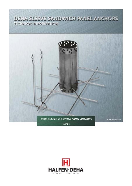
DEHA SLEEVE SANDWICH PANEL ANCHORS - SALAM Enterprises
DEHA SLEEVE SANDWICH PANEL ANCHORS - SALAM Enterprises
DEHA SLEEVE SANDWICH PANEL ANCHORS - SALAM Enterprises
Create successful ePaper yourself
Turn your PDF publications into a flip-book with our unique Google optimized e-Paper software.
PRODUCTION METHODSThere are two methods of production:• facing layer down method• facing layer up methodFACING LAYER DOWN METHODsupporting anchors of a lower loadrating. The low water absorption capacityhas a favourable effect on the shrinkage ofthe concrete, (see page 6 “Deformation”)Placing the Separating Foilanchor during the vibration procedure,otherwise separation of the facing layerconcrete may occur which can lead tocolour variations and show the outline ofthe sandwich panel anchor.Production of Facing Layerloadbearinglayerheat insulationlayerfacing layer• Placing of the reinforcement in themould.Recommendation:Prior installation of the supportinganchor.• Concrete is placed evenly in the mould.• Compaction of the concrete usingexternal vibrators.Placing of the Heat Insulation Layer• Insulation material to be fully insertedin area of sandwich panel anchor. Ifusing high-grade non-compressibleinsulation material, then appropriatearea is to be properly cut out for thesandwich panel anchor. No cavities maybe formed, which subsequently infillwith concrete and produce a thermalbridge.Recommendation:The heat insulation layer to be installed in2 layers, the butt joints staggered. In thecase of single layer heat insulation, thejoints are to be produced as steppedjoints or sealed using adhesive tape. Thisprevents concrete from entering the joint.If using insulation with a high grossdensity, e.g.hard polystyrene foam (lowthermal conductivity and minimal waterabsorption) then the thickness of the heatinsulation can be reduced. The resultingincrease of the Ioadbearing capacity ofthe connecting anchor permits the use of• The separating foil prevents concreteslurry from entering the butt joints ofthe heat insulation. Adhesion of theheat insulation to the Ioadbearing layeris prevented. This is important if usingrough expanded polystyrene insulationmaterial. In order to ensure optimumflexibility of the facing layer, a foil layershould also be installed between thefacing layer and insulation layer. Thefoil can be omitted if using a high-gradeinsulating material which has a smoothsurface.Production of the Loadbearing Layer• Installation of the loadbearing layerreinforcement• A traversable non-compressible insulationlayer material facilitates installationInstallation of the Connecting Pins• The connecting pins are installed abovea reinforcement bar crossing of the loadbearinglayer reinforcement throughthe heat insulation layer into the facinglayer to the base of the mould. In orderto avoid the pin ends becoming visibleat the face, the pins should be pulledback slightly after contact with themould base. (This is especially importantfor exposed aggregate, blasted or bushhammered finishes). Subsequent compactionof the facing layer concrete isnecessary (see page 24 “ConnectingPins”).Placing of Loadbearing Concrete Layer• The concrete is distributed evenly in themould and compacted with a poker typevibrator.Important:there must be no contact between thevibrator poker and sandwich panelFACING LAYER UP METHODfacing layerThe production of a sandwich panel inthis method is in the reverse order to thepreviously described production procedure.Here the loadbear-ing layer is placed first.Clip-on pins or clip-on stirrups are to beused (see page 24 “Connector Pins”).<strong>SANDWICH</strong> <strong>PANEL</strong> AS SEMI-PREFABRICATED ELEMENTheat insulationlayerloadbearinglayerIn this case, a prefabricated facing panelis provided with heat insulation and usedas lost shuttering. The loadbearing layeris produced by in-situ concrete.prefabricated facing layercast-in-place concrete5
DEFORMATION OF <strong>SANDWICH</strong> <strong>PANEL</strong>SWARPING CAUSED BY SHRINKAGESandwich panel elements often showwarping deformations. Particularly largepanels with a length of more than 5 mare affected by such deformations.Shrinkage is mainly dependent on thedrying out of the concrete. This dryingproceeds from the exterior inwards. Theinner and outer layer of the sandwichelement warp in opposite directions.These deformations are more pronouncedwhen drying proceeds more rapidly at theexterior and more slowly on the interior.Deformations can be expected in sandwichpanels exposed to solar radiationand wind in the first few days afterproduction.Insulation with a low water absorptioncapacity should be used. Insulationmaterials with a high water absorptioncapacity transfer moisture to the concreteduring the drying out procedure. Thisleads to differential drying out of theexternal and internal layers of the sandwichelement.rapid dryingslow dryingFurther, concrete technology measures canbe used in order to reduce shrinkage andthe resulting detrimental consequences toa minimum. A low water/cement ratioshould be used. The top size of theaggregate is to be chosen according tothe workability reinforcement and dimensionsof the sandwich panel. The smalleraggregate content is to be chosen so thatthe voids are infilled. The cement binderand fine aggregate content is to be keptlow. The use of concrete additives,especially wetting agents, air-entrainingagents, damp-proofing and permeabilityreducing agents and retarders can have avery detrimental effect on the shrinkagebehaviour of the concrete.It is impossible to avoid separation whencompacting the concrete. Large andheavy components of the concrete mixsink to the bottom during vibration. Thesmaller, lighter and wetter componentsremain at the top. This results in a largershrinkage value at the top compared tothe bottom ('top' and 'bottom' refer tothe position of the panel during concreteplacing). With lightweight concrete thewarping tendencies are completelyreversed, as the aggregate material hereis lighter than the other concrete mix andrises the top during vibration.The vibration procedures are to be limitedin both intensity and duration in order tokeep separation to a minimum.The type and amount of warping of asandwich panel is dependent on whetherit is produced. In the case of sandwichelements produced in the facing layerdown method, the warping tendency inthe loadbearing layer caused by timedependentshrinkage (1. drying out) isadded to the structurally dependent differentialshrinkage (2. mix separation). Inthe facing layer, the warping tendenciesfrom (1) and (2) counteract each other (3),and it remains virtually plane. The stifferloadbearing foyer imposes its warping tothe facing layer via the connectinganchors (4).producedin place 1 2 3 4(1+2)For sandwich panels produced in thefacing layer up method, the warpingtendencies (1) and (2) are counteractive,the load-bearing layer remains virtuallyplane (3). The warping tendencies fromthe facing layer (1) and (2) are addedtogether.The warping of the facing layer isprevented by restraint from the sandwichpanel anchorages if adequate connections(e.g. retaining anchors) properly link bothlayers together(4).producedin place 1 2 3 4(1+2)The prevention of warping of the sandwichpanel by using sandwich panelanchorages produces forces which canlead to cracks in the facing layer. Careshould be taken to prevent warping.Apart from the previously described productionengineering measures, suitableconstruction measures can be chosen inthe design of the prefabricated elements.6
CONSTRUCTION DETAILS<strong>PANEL</strong> LENGTHAvoid panel lengths over 6 m !Longitudinal changes caused by temperaturechanges can cause damage to sandwichpanels. For this reason the length ofthe facing layer should not exceed 6 m.If, for architectural or constructional reasons,longer elements cannot be avoided,it is recommended that the facing layerbe separated; the loadbearing layer canbe produced in one piece.L 6,00 mL 6,00 mANCHORAGE CENTREWherever possible, the anchorage centreshould be situated in the middle of thepanel.The longitudinal change Δ L caused bytemperature change increases with increasingdistance from the anchorage centre(VZ), the fulcrum. In order to keep longitudinalchanges to a minimum, theanchorage centre should be situated inthe middle of the panel.The rigidity of the links (retaining andsupporting ties and anchors) prevent deformationsof the element. The resultingconstraining forces can lead to damage.Larger heat insulation thicknesses reducethese constraining forces by improveddeformation behaviour of the retainingmeans. The maximum permissiblespacings of the connecting links from theanchorage centre are therefore dependenton the thickness of the heat insulationlayer (see table 17+18).L2L2HEAT INSULATION LAYERIt is recommended that a material withhigh gross density and low thermal conductivitybe used.Extruded hard polystyrenefoam boards (e.g. Styrofoam,Styrodur) are ideal here. This can lead toa reduction in the thickness of the heatinsulation and thus to an increase in theloadbearing capacity of the sandwichpanel anchorage. Alternatively, a supportinganchor of a lower load rating can beused.The surface of the heat insulation materialshould be smooth to achieve minimaladhesion between the concrete and theinsulation material. A separating foil canbe used. In order to avoid cold bridgesthe thermal insulation should be installedin two layers with staggered joints.Alternatively the joint is to be sealed withadhesive tape. If insulation material witha rough surface is to be used, then aseparating foil must be placed betweenconcrete and the heat insulation layer.8
CONSTRUCTION DETAILSFIXING OF WINDOWS AND DOORSThe facing layer must be non-rigidly fixedto the loadbearing layer. Additional fixingpositions such as doors or windows fastenedto the facing layer leads to constrainingforces, which may cause cracking.CORNER CONSTRUCTIONIf the sandwich panels are to go roundcorners at building perimeters, windowsor door openings, then the followingpoints must be observed:Between facing layer and heat insulationin the area of the facing going aroundthe corner an air gap is to be provided .Alternatively, the heat insulation in thisarea can be of soft fibre (e.g. mineralwool).Connecting pins must not be used in theshort angled part of the facing layer corner.air gap≤ 0,45 mair gaptwo-layerpossible dummy jointair gapair gaploadbearinglayerstepped jointheat insulationlayerfacing layerCONSTRUCTION OF LOADBEARING LAYERThe stiffer loadbearing layer imposes itsdeformation on the facing layer. In orderto reduce deformation of the loadbearinglayer to a minimum, its minimum thicknessshould fixed at double the thicknessof a facing layer. The stiffness can beincreased by cast-on brackets at theperimeter of the loadbearing layer,(in theform of window ledges, bearings) tomeet special requirements.CONSTRUCTION OF THEFACING LAYERThe minimum thickness of the facinglayer is 70 mm. Due to the reinforcementcover requirements, 60 mm thick facinglayers are only possible if the reinforcementis coated or otherwise protectedagainst corrosion.A minimum reinforcement of 131 mm 2 /mis to be provided.The required additional reinforcement inthe facing layer in the area of the sandwichpanel anchor is given in the typetest report.9
CONSTRUCTION DETAILSCONCRETE QUALITYLIGHTWEIGHT CONCRETEThe loadbearing tables for the sandwichpanel anchor are based on the use of aminimum concrete strength of 35N/mm 2 . The permissible loading of thesandwich panel anchor must be reducedif using a concrete strength 25 N/mm 2 .For the sake of simplicity, the existingnormal and shear force loads are increasedby a factor of 1.4. The dimensioningof the required sandwich panel anchor iscarried out using the increased loadvalues.Should the facing layer or loadbearinglayer be produced in lightweight concrete,then permissible loading of the sandwichpanel anchor must be reduced. Thereduction factor is determined as follows:• from the ratio of nominal strength ofthe lightweight concrete to that ofstandard concrete with concretestrength of 35 N/mm 2.• from the ratio of the varying factors ofthe partial area loading of standardconcrete as given by DIN 1045 (factor1.4) and of lightweight concrete as givenby DIN 4219 (factor 1.0).By increasing the embedding depth ofthe supporting anchor one can increasethe loadbearing capacity of the sandwichpanel anchor.If using a lightweight concrete thepermissible loading of a sandwich panelanchor is determined as follows :perm. Qred permissible reduced loadingperm. Qa inca15 1.0perm.Q red = perm. Q x x x35 1.4permissible loading fromtable 4 to 7 for sleeve anchortable 13 to 16 for flat anchorincreased embedding lengthembedding length fromtable 1 for sleeve anchors50 mm for flat anchors15 (N/mm 2 ) nominal strength of LB 15(lightweight concrete)35 (N/mm 2 ) nominal strength of concrete1.0 factor of partial area loading of lightweightconcrete as given by DIN 42191.4 factor of partial area loading of standardconcrete as given by DIN 1045(a inca(2REAR-VENTILATED <strong>SANDWICH</strong> <strong>PANEL</strong> (4-LAYER <strong>PANEL</strong>)A sandwich construction may be constructedas a 4-layer panel to avoid condensationproblems. A 40 mm gap for rearventilation is adequate.A simple, economical and quick solutionis offered by the p.v.c. air layer insert, size700 x 1500 mm (designation SPA-DH)The air layer inserts are placed after concretingof the facing layer.Openings are to be provided in the heatinsulation layer for the supportinganchors.After placing of separating layer (foil) theloadbearing layer concrete is poured inposition.It should be noted that the permissibleloading of the sleeve sandwich panelanchor is reduced for 4-layer panels.The heat insulation layer is then placed inposition.rear ventilation10
CONSTRUCTION DETAILSFIXING OF THE <strong>SANDWICH</strong> <strong>PANEL</strong>S TO THE BUILDING STRUCTURESandwich panels are mainly used for reinforcedconcrete or steel framework constructions.Vertical load transfer for superimposedelements is only via the loadbearinglayer. The loads from facing layersare transferred via the sandwich panelanchors to the loadbearing layer.The lowest panel bears on the floor,foundations or on column brackets.The horizontal load transfer (wind, tiltingforces) is via the connecting elements(anchor rails, profiled steel sections, screwcouplings) between the loadbearing layerand the floor or column.The superimposed sandwich elements arerigidly connected via a pinned fixing.All steel parts which are not permanentlyprotected against corrosion by being concretedin or by mortar grouting, are to beof stainless steel.facing layerheat insulation layerloadbearing layerfacing layerheat insulation layerloadbearing layer312121 Halfen channel2 Steel angle with slot3 Bearing (e.g. elastomeric bearing)1 Pin fixing2 Bearing (e.g. elastomeric bearing)8562 41731 tolerance joint2 bearing joint in accordance withbearing thickness3 bearing (e.g.elastomeric bearing)4 steel pin or equivalent connection5 steel angle with slot6 Halfen channel7 pocket for steel pin, mortar grouting8 grouting concrete, min. 25N/mm 211
SUPPORTING SYSTEMSSome of the systems of load transfer forthe facing layer are listed below. Thedesignation of the individual supportsystems are fixed and are reproduced in acomputer dimensioning program forsandwich-type connector constructions.Supporting System: MVASupporting System: FA-FAOne sleeve sandwich panel anchor assupport at the cendroid. Crossed connectorpins as torsion anchor.Application :rectangular panels without openingspanels can be rotatedTwo flat anchors as supports (withunsymmetrical load distribution, flatanchors of same load rating should beused to avoid confusion).One horizontal flat anchor or (crossedconnector pins) as stiffeningApplication:long slender rectangular panelsSupporting System: MVA-FA or FA-MVASupporting System: FA-FAOne sleeve sandwich panel anchor andone flat anchor as supports.Used for unsysmmetrical load distributionwith sleeve sandwich panel anchor takinglarge loadApplication:large rectangular panels with heavyfacing layers rectangular panels withopeningsTwo flat anchors as supports. Fulcrum ofanchors located on centroid of panel.Important for thin heat insulation layers(observe e-values)Application:panels with large openings in the centreWindow or door openings may preventthe positioning of the anchorage centreat the middle of the panel.The possible deformation characteristicsof the supporting and retaining anchorsdetermine their maximum possible spacingfrom the anchorage centre.When determining the supporting systemto be used, these maximum spacings forthe connector pins (e H given in table 18 )and for flat anchors (e given in table 17 )are to be observed.12
<strong>DEHA</strong> <strong>SANDWICH</strong> <strong>PANEL</strong> ANCHORAGES -OVERVIEWThe <strong>DEHA</strong> sandwich panel anchoragesystem is type tested for all load caseslisted on page 4. The wind loads on constructionelements up to a height of 100m above site level and at building perimeterzones are taken in to account.Users and proofing engineers are notrequired to carry out static calculationsfor the sandwich panel anchoragesystem. Only the chosen loadbearingsystem of the building structure requiresverification. The <strong>DEHA</strong> sandwich panelanchorages are made of stainless steel,material quality W 1.4401 and W1.4571. A reduction of 10 % is recommendedwhen calculating the heat transmissionresistance according to DIN 4108due to the sandwich panel anchor.SOFTWARE FOR CALCULATING <strong>DEHA</strong> <strong>SANDWICH</strong> <strong>PANEL</strong> ANCHORAGESFor calculation of sandwich panel anchoragesthe weight and the centre of gravityof facing layer must be calculated. Thenthe supporting system can be selected.After that the permissible loadings of theanchors must be determined and therequired types selected from tables.All these jobs can be performed quicklyand easily with our software programs.The programs are available for thesystems <strong>DEHA</strong> with sleeve sandwichpanel anchor, flat anchor and connectorpins or system HALFEN with anchors typeSPA and connector pins.free download at:www.halfen-deha.deSUPPORTING <strong>ANCHORS</strong>sleeve sandwich panel Anchor (MVA)designation 5300 - H - dia.The cylindrical sleeve sandwich panelanchor can be used as a single elementtogether with connector pins to transferload. Both ends are provided with roundand oval holes. The round holes are forinserting the reinforcing bars, the oval forbonding with the concrete.The diameter and height of the anchor isembossed on its face for identificationpurposes.Flat Anchor (FA)designation 5301 - L - H t= 1.5 mm5302 - L - H t= 2.0 mm5303 - L - H t= 3.0 mmThe flat anchor is a 1.5, 2 or 3 mm thickplate. Two opposite ends are providedwith round and oval openings. The roundholes are for inserting the reinforcingbars, the oval for bonding with the concrete.The flat anchor can only be used asa supporting anchor when in combinationwith a sleeve sandwich panel anchor ormore flat anchors.The anchor length and height are embossedon the anchor for identification purposes.sleeve sandwich panel anchordia.HFlat anchorLHt14
<strong>DEHA</strong> <strong>SANDWICH</strong> <strong>PANEL</strong> ANCHORAGES -OVERVIEWRETAINING <strong>ANCHORS</strong>Connector Pindesignation SPA-N (5440)Connector pins are u-shaped bent barswith bar diameter: 3.0mm 4.0mm and5.0 mmmaterial: 1.4401/1.4401 S355Clip-on Pindesignation SPA-A (5540)Clip-on pins are connector pins with anclosed end bent at 90°bar diameter: 3.0mm 4.0mm and 5.0 mmmaterial: 1.4401 S355Clip-on Stirrupdesignation SPA-B (5940)Clip-on stirrups can be used as an alternativeto the clip-on pins.bar diameter: 3.0mm 4.0mm and 5.0 mmmaterial: 1.4401 S355TORSION <strong>ANCHORS</strong>.Crossed Connector Pin2 x part no. 5440 - 0 - LThe crossed connector pin consists of twoconnector pins set at 45* inserted intoone another.4.0mm 5.0 mm1.4401 K700bar diameter: material :Flat Anchorpart no. 5301 -L-HA flat anchor may be used as an alternativeto the crossed connector pin.Application:- if the load acting on the torsion anchorexceeds that which can be taken up by acrossed connector pin15
CALCULATION OF SUPPORTING ANCHORTable 8Permissible loading Q (kN) for 4-layer panels, f ≤ 80 mmb mmdia. mm517610212715317820422925528030 40 50air gap imposssible60 70 80 906.3 5.6 4.9 4.212.5 11.2 10.0 8.718.0 16.5 14.5 13.023.0 21.0 19.0 17.028.0 26.0 23.5 21.533.0 30.5 28.0 25.038.0 35.0 32.0 29.042.5 39.5 36.0 33.047.0 43.0 39.0 37.050.0 45.0 40.0 37.0100 110 120 130 140 150REQUIRED ADDITIONAL REINFORCEMENTTable 9Required additional reinforcement (mm 2 ) for 3-Layer PanelsThickness ofheat insulation layerb (mm)30405060708090100110120130140150Anchor diameter (mm)51 76 102 127 153 178 204 229 255 28018 25 31 3720 30 40 47 60 7018 20 23 35 48 60 69 78 8624 28 32 45 58 70 78 86 9429 35 40 53 67 80 87 94 10029 36 42 58 73 88 94 99 10429 36 43 60 78 95 100 104 10826 36 43 61 80 88 96 104 11226 36 44 63 84 92 100 109 11726 36 45 65 88 96 105 113 12126 36 46 67 91 99 108 117 12524 36 47 68 94 102 111 120 12822 36 48 70 96 104 113 122 131Table 10Required additional reinforcement (mm 2 ) for 4-Layer PanelsThickness ofheat insulation layerb (mm)30405060708090100110120130140150Anchor diameter (mm)51 76 102 127 153 178 204 229 255 28023 55 70 85 110 136 162 184 206 22827 61 78 95 122 150 176 196 216 23631302826242321676767656565658687888889899010410610811011211511813313613914014214414616216617017217517717919019520019319820120420821221721421922523022623023423524024925518 63 90 120 148 181 207 233 25814 60 91 122 150 184 210 236 26124324725125626127228028428718
INSTALLATION OF <strong>SLEEVE</strong> <strong>SANDWICH</strong> <strong>PANEL</strong> ANCHOR<strong>DEHA</strong> sandwich panel anchors can beinstalled when the facing layer reinforcementis tied together. The anchoring barsare first inserted in the lower row ofround holes of the sleeve sandwich panelanchor, so that they are positioned parallelto the lower layer of the reinforcementmesh. Anchor-ing bars are then insertedat right angles to these in the upper rowof round holes. These are then almostparallel to the upper row of bars of thesteel mesh reinforcement. By turning thesleeve sandwich panel anchor through45° the lower anchor-ing bars are thensituated beneath the lower row ofbars,and the upper anchor-ing bars abovethe upper row of bars of the steel meshreinforcement. Binding to the reinforcementmesh is not necessary. The nowcomplete reinforcement cage can then beinstalled in the mould.As an alternative to the previously describedmethod of installation, the sleeve sandwichpanel anchor can be set from aboveonto the first placed reinforcement, butwithout subsequent placing of anchoringbars beneath the reinforcement mesh.This method is strongly recommended forslender facing layers. The sleeve sandwichpanel anchor should then however betied to the reinforcing mesh in order toavoid displacement during concreteplacement.19
CALCULATION OF SUPPORTING ANCHOR<strong>DEHA</strong> FLAT ANCHORDesignation 5301 - H (mm) - L (mm)1.5 mm thickDesignation 5302 - H (mm) - L (mm)2.0 mm thickDesignation 5303 - H (mm) - L (mm)3.0 mm thickMaterial 1.4571 S355bfL≥ 50mmHDetermination of Height (H)The height (H) of the flat anchor is dependent on the thickness of the heat insulationlayer (b) and the minimum embedding depth of 50 mm. With larger embedding depths,the height of the flat anchor is to be chosen accordingly.Table 11heat insulation layer (b) in mm30 40 50 60 70 80 90 100 110 120 160 180 200 240H = 150 t=1.5H = 175 t=1.5H = 200 t=1.5H = 200 t=2.0H = 225 t=1.5H = 225 t=2.0H = 260 t=2.0H = 260 t=3.0H = 280 t=3.0H = 300 t=3.0H = 350 t=3.0tEmbedding DepthsThe minimum embedding depth of the<strong>DEHA</strong> flat anchor is 50 mm. An increaseof the loadbearing capacity or an increasedsafety factor against concrete fracturecan be attained by increasing the embeddingdepth. The <strong>DEHA</strong> flat anchor is typetested as a supporting anchor for a heatinsulation layer thickness of up to 240mm.The limitations of use regarding facinglayer thickness as given for the sleevesandwich panel anchor do not apply.Anchoring in ConcreteThe anchoring bars are to be provided in the facing and loadbearing layers. The numberof anchoring bars depends on the length of the flat anchor.Flat anchordesignation 530t-H-LLLengthL mmSymbolAnchoring barsBSt 500Sl=40080 2× 4 dia.6 mmH120160, 200,240, 280320, 360, 4002× 5 dia.6 mm2× 6 dia.6 mm2× 6 dia.6 mm20
CALCULATION OF SUPPORTING ANCHORDetermination of LengthThe length (L) of the flat anchor is dependent on the loading and the thickness (b) of the heat insulation layer.Table 13Permissible loading Q (kN) of flat anchors with a thickness t = 1.5, 2.0 and 3.0 mm for facing layer thickness f ≤ 80mm for 3- and 4- layer panels(N = 4.2 kN in accordance with type test)tmm1.52.03.01.52.03.01.52.03.01.52.03.01.52.03.01.52.03.01.52.03.01.52.03.01.52.03.01.52.03.0Lmm404040808080120120120160160160200200200240240240280280280320320320360360360400400400Heat insulation layer (b) in mm30 40 50 60 70 80 90 100 110 120 130 140 150 1802.3 1.8 1.3 1.01.85.48.511.514.617.720.823.926.930.05.1 4.84.57.08.1 7.7 7.410.211.1 10.714.2 13.717.3 16.820.3 19.823.4 22.926.5 26.029.6 29.110.314.513.319.316.323.319.327.322.431.225.535.528.639.40.81.5 1.2 0.9 0.7 0.6 0.43.96.16.99.59.813.612.818.315.822.518.826.521.831.024.935.327.939.33.25.26.38.99.312.612.317.215.221.618.225.821.230.724.335.027.239.12.54.35.78.28.711.711.716.214.720.817.725.020.630.523.534.826.439.01.93.75.17.47.911.110.815.313.819.716.723.919.728.922.633.125.537.31.33.13.66.56.810.49.614.412.518.615.122.718.527.221.531.424.535.50.52.52.65.75.19.87.813.510.617.513.721.616.925.620.029.723.133.81.22.24.65.26.69.19.412.613.016.317.420.122.623.928.727.935.531.943.21.12.04.44.76.38.49.011.712.415.216.618.721.522.227.326.233.830.141.11.0 0.71.74.2 3.54.26.0 5.17.78.5 7.210.311.7 10.013.515.7 13.817.020.4 17.520.025.9 22.524.032.0 28.028.039.0 34.0Table 14Permissible loading Q (kN) of Flat anchors with a thickness t = 1.5, 2.0 and 3.0 mm for facing layer thickness f = 90mm for 3- layer panels(N = 5.8 kN in accordance with type test)tmm1.52.03.01.52.03.01.52.03.01.52.03.01.52.03.01.52.03.01.52.03.01.52.03.01.52.03.01.52.03.0Lmm404040808080120120120160160160200200200240240240280280280320320320360360360400400400Heat insulation layer (b) in mm30 40 50 60 70 80 90 100 110 120 150 180 210 2401.9 1.6 1.0 0.51.5 1.2 0.9 0.61.6 1.42.8 2.5 2.1 1.81.2 0.7 0.55.0 4.6 4.3 3.8 3.2 2.7 1.9 0.96.0 5.3 4.5 3.8 3.2 2.5 1.86.0 5.6 5.3 4.9 4.7 4.4 4.1 3.5 3.0 2.3 1.68.0 7.8 7.1 6.78.78.811.2 10.8 10.2 9.612.913.014.3 13.7 13.2 12.618.318.417.5 16.8 16.2 15.722.825.020.6 20.0 19.4 18.726.833.023.5 23.0 22.5 21.830.842.026.6 26.2 25.5 24.935.052.329.8 29.2 28.5 28.039.060.06.28.28.39.112.112.212.117.117.215.021.923.318.026.030.821.130.439.324.034.749.027.338.857.25.57.77.88.511.311.311.515.816.014.520.921.717.425.128.720.529.936.723.534.545.826.438.554.34.87.27.37.810.510.510.814.614.813.820.020.016.824.326.519.729.534.022.634.242.525.538.351.54.06.36.96.89.810.09.713.714.012.718.819.015.123.025.218.527.932.221.532.440.224.536.548.82.45.36.55.59.29.48.312.913.311.317.718.014.021.823.817.126.230.320.130.637.823.034.646.21.04.46.13.38.58.96.112.012.59.016.517.012.020.522.515.224.628.518.528.835.521.532.843.53.15.2 4.6 4.2 3.55.87.6 6.7 6.0 5.49.010.6 9.2 8.5 7.512.014.912.511.5 10.415.519.2 16.5 15.0 13.518.524.6 21.0 19.2 17.322.530.8 27.0 24.0 21.626.437.5 32.8 29.5 26.521
CALCULATION OF SUPPORTING ANCHORTable 15Permissible loading Q (kN) of flat anchors with a thickness t = 1.5, 2.0 and 3.0 mm for facing layer thickness f = 100mm for 3- layer panels(N = 6.86 kN In accordance with type test)tmm1.52.03.01.52.03.01.52.03.01.52.03.01.52.03.01.52.03.01.52.03.01.52.03.01.52.03.01.52.03.0Lmm404040808080120120120160160160200200200240240240280280280320320320360360360400400400Heat insulation layer (b) in mm30 40 50 60 70 80 90 100 110 120 150 180 210 2401.6 1.2 0.51.4 1.0 0.6 0.22.1 1.9 1.7 1.5 1.3 1.2 1.0 0.6 0.54.7 4.4 3.5 3.4 2.7 1.9 1.2 0.25.0 4.5 3.9 3.4 2.8 2.1 1.65.1 4.7 4.4 4.0 3.8 3.6 3.3 2.7 2.5 2.1 0.67.8 7.4 6.9 6.47.87.910.9 10.4 9.8 9.311.811.914.0 13.4 12.8 12.316.917.017.0 16.5 15.8 15.322.524.520.1 19.6 19.0 18.326.332.423.2 22.7 22.1 21.330.641.826.2 25.7 25.1 24.534.652.029.7 28.8 28.2 27.438.760.05.77.37.38.611.111.011.615.915.814.621.322.617.625.931.220.630.138.624.634.348.226.738.456.65.06.86.87.910.310.210.914.814.713.920.020.816.825.330.119.829.535.422.734.044.525.838.053.24.26.26.37.29.59.410.213.713.713.218.818.916.124.825.019.029.032.222.033.740.724.837.749.83.35.55.96.19.08.99.012.912.812.017.718.114.923.123.617.827.330.520.731.838.523.635.847.11.44.75.74.88.58.47.612.112.110.516.717.413.421.522.316.425.728.919.429.936.322.434.044.52.95.42.38.07.95.011.311.38.015.715.711.019.821.014.124.027.217.228.034.120.432.141.92.84.6 4.0 3.5 3.45.36.88.49.911.613.615.018.118.123.222.029.425.836.12.26.0 5.3 4.85.08.7 7.7 6.48.012.0 10.7 9.611.016.0 14.2 12.814.020.4 18.2 16.517.225.8 23.0 20.720.431.7 28.3 25.4Table 16Permissible loading Q (kN) of flat anchors with a thickness t = 1.5 , 2.0 and 3.0 mm for facing layer thickness f = 120 mm for 3- layer panels(N = 9.4 kN In accordance with type test)tmm1.52.03.01.52.03.01.52.03.01.52.03.01.52.03.01.52.03.01.52.03.01.52.03.01.52.03.01.52.03.0Lmm404040808080120120120160160160200200200240240240280280280320320320360360360400400400Heat insulation layer (b) in mm30 40 50 60 70 80 90 100 110 120 150 180 210 2404.0 3.8 3.3 2.62.62.69.7 8.9 8.0 7.07.17.113.5 12.8 12.3 11.512.112.116.5 16.0 15.1 14.318.018.019.7 19.0 18.4 17.625.425.422.5 22.1 21.5 20.529.934.025.9 25.2 24.5 23.634.044.029.0 28.3 27.6 26.838.055.02.52.52.66.76.76.710.611.411.413.516.817.016.523.823.819.729.131.822.733.541.225.837.651.52.42.42.56.36.36.39.810.610.612.815.716.015.722.222.218.528.329.721.633.138.324.737.248.02.02.12.55.75.96.09.09.910.012.014.515.015.020.520.517.927.527.520.832.635.523.736.844.52.02.02.34.85.55.67.89.39.410.513.814.113.519.519.516.525.926.119.530.733.722.334.842.22.02.23.25.25.35.08.88.88.613.213.311.618.518.514.624.224.617.628.731.820.632.839.81.92.00.34.84.93.08.28.25.812.312.49.017.317.412.022.623.215.226.830.018.430.837.51.51.7 1.7 1.5 1.13.54.1 3.8 3.3 3.06.57.1 6.4 5.6 5.09.810.5 9.3 8.5 7.513.115.0 13.0 12.0 10.516.120.0 17.5 15.8 14.020.026.0 22.8 20.3 18.024.032.5 28.4 25.5 22.522
CALCULATION OF SUPPORTING ANCHORPERMISSIBLE E-VALUESThe e-values given in table 17 are themaximum possible spacings of a flatanchor from the anchorage centre.If these values are exceeded, then themobility of the flat anchor must be ensuredby installation of additional heat insulationstrips.Table17Permissible e-values (m) for flat anchors with a thickness t=1.5, 2.0 and 3.0 mm forfacing layer thicknesses up to f=120mm for 3- and 4-layer panelstmm1.52.03.01.52.03.01.52.03.01.52.03.01.52.03.01.52.03.01.52.03.01.52.03.01.52.03.01.52.03.0Lmm404040808080120120120160160160200200200240240240280280280320320320360360360400400400Heat insulation layer (b) in mm30 40 50 60 70 80 90 100 110 120 150 180 210 2401.50 2.30 3.20 3.603.603.602.00 3.30 3.50 3.603.603.602.00 3.30 3.50 3.603.603.602.00 3.30 3.50 3.603.603.602.00 3.30 3.50 3.603.603.602.50 4.00 3.50 3.603.603.602.50 4.00 3.50 3.603.603.602.50 4.00 3.50 3.603.603.602.50 4.00 3.50 3.603.603.602.50 4.00 3.50 3.603.603.603.603.603.603.603.603.603.603.603.603.603.603.603.603.603.603.603.603.603.603.603.603.603.603.603.603.603.603.603.603.703.703.703.703.703.703.703.703.703.703.703.703.703.703.703.703.703.703.703.703.703.703.703.703.703.703.703.703.704.204.204.204.204.204.204.204.204.204.204.204.204.204.204.204.204.204.204.204.204.204.204.204.204.204.204.204.204.204.604.604.604.604.604.604.604.604.604.604.604.604.604.604.604.604.604.604.604.604.604.604.604.604.604.604.604.605.105.105.105.105.105.105.105.105.105.105.105.105.105.105.105.105.105.105.105.105.105.105.105.105.105.105.105.105.605.605.605.605.605.605.605.605.605.605.605.605.605.605.605.605.605.605.605.605.605.605.605.605.605.605.605.607.007.008.408.409.809.8011.2011.207.007.00 8.40 9.80 11.207.007.00 8.40 9.80 11.207.007.00 8.40 9.80 11.207.007.00 8.40 9.80 11.207.007.00 8.40 9.80 11.207.007.00 8.40 9.80 11.207.007.00 8.40 9.80 11.207.007.00 8.40 9.80 11.20INSTALLATION OF FLAT <strong>ANCHORS</strong>Firstly, two anchor bars (L = 400mm)bent at their midpoint by 30° are insertedin the outer holes of the upper bottomrow of round holes.The flat anchor is then set at the givenposition on the mesh reinforcement. Theanchorage bars are placed beneath thelower level of the reinforcement meshand inserted through the lower bottomrow of round holes.The bent anchorage bars facing upwardsare turned down, the ends must now betied to the mesh reinforcement.23
CALCULATING THE RETAINING <strong>ANCHORS</strong>CONNECTOR PINSConnector pindesignation SPA-N (5440)Material 1.4571 or 1.4401 S355Clip-on pindesignation SPA-A (5540)Material 1.4401 S355Clip-on Stirrupdesignation SPA-B (5940)Material 1.4401 S355The connector pin is mainly used in thefacing layer down production.(see section “Production Methods”).The clip-on pin is mainly used in thefacing layer up production. Insertingbefore concreting to the cross-point ofmesh reinforcement. This ensures theminimum embedding length.Alternatively to the clip-on pins the cliponstirrup with closed ends can be use.Lf b aLf b aLf b aDETERMINATION OF SIZESThe size of the connector pins is to be determined using the following table.Maximum distances between connector pin and anchorage centre (e H max.)Table 18fmm60708090100110dia.-L30 40 50 60 70 80 90 100 110 120 130 140 1503.0-140 3.0-160 4.0-180 4.0-200 4.0-220 4.0-240 5.0-260e H max 1.6 2.6 3.8 4.0 5.3 6.7 8.3 8.3 8.3 8.3 8.3 8.3 8.3dia.-L 3.0-160 3.0-180 4.0-200 4.0-220 4.0-240 5.0-260 5.0-280e H max 1.3 2.0 2.9 4.0 5.3 6.7 8.3 8.3 8.3 8.3 8.3 8.3 7.0dia.-L 3.0-160 3.0-200 4.0-200 4.0-240 5.0-260 5.0-280 5.0-320e H max 1.3 2.0 2.9 4.0 5.3 6.7 8.3 7.0 7.0 7.0 7.0 7.0 7.0dia.-L 4.0-180 4.0-200 4.0-220 4.0-240 5.0-260 5.0-280 5.0-300e H max 1.3 2.0 2.9 4.0 5.3 6.7 8.3 7.0 7.0 7.0 7.0 7.0 7.0dia.-L 4.0-180 4.0-200 4.0-220 5.0-240 5.0-260 5.0-280 5.0-300 5.0-320e H max 1.3 2.0 2.9 4.0 5.3 6.7 8.3 7.0 7.0 7.0 7.0 7.0 7.0dia.-L 5.0-2405.0-260 5.0-280 5.0-300 5.0-320e H maxdia.-L120 eH maxConnector pins (e H max. in m valid for all types of connector pins)5.0-240Heat insulation layer (b) mm5.0-260 5.0-280 5.0-300 5.0-320 6.0-3402.5 3.4 4.4 5.6 6,,9 7.0 7.0 7.0 7.0 7.0 7.0The e H -values (m) given in table 18 mustbe adhered to. They ensure adequatemobility of the pins and prevent damagecaused by additional constraining forces.If the permissible values are exceeded,then additional strips of heat insulation inthe area of the pins are required to allowmovement.The <strong>DEHA</strong> connector pin is also typetested as an independent supportinganchor. In this case however all principalloads and additional loads must be determined.Table 19diameterdia. 3.0 mmdia. 4.0 mmdia. 5.0 mmProposed loadbearing values forConnector pinsDruck1.98 kN bei e = 60 mm3.92 kN bei e = 90 mm5.85 kN bei e = 120 mmSog3.32 kN3.92 kN3.92 kNMinimum LengthThe minimum length of the connectorpins can determined approximately asfollows:thickness of the facing layer (f)+ thickness of the heat insulation layer (b)+ embedding length (a)= connector pin length (L)The embedding length (a) are given intable 1 (sleeve sandwich panel anchor)page 16.24
CALCULATING THE RETAINING <strong>ANCHORS</strong>Table 20 Clip-on pin (e H max. see table 18)fmm60708090100Heat insulation layer (b) mm30 40 50 60 70 80 90 100 110 120 130 140 150dia.-L 3.0-140 3.0-160 4.0-160 4.0-2004.0-2505.0-280dia.-L 3.0-160 3.0-180 4.0-2004.0-250 5.0-280dia.-L 3.0-160 3.0-180 4.0-2005.0-250 5.0-280dia.-L 4.0-160 4.0-200 5.0-2505.0-280dia.-L 4.0-160 4.0-200 5.0-2005.0-250 5.0-280110 dia.-L 5.0-200 5.0-250 5.0-280120 dia.-L 5.0-2005.0-2505.0-280Table 21 Clip-on stirrup (e H max. see table 18)fmm6070809010011030 40 50 60 70 80 90 100 110 120 130 140 150dia.-L3.0-160 4.0-180 4.0-200 4.0-220 4.0-240 5.0-240 5.0-260dia.-L 3.0-160 4.0-180 4.0-200 4.0-220 5.0-240 5.0-260dia.-L 3.0-160 4.0-180 4.0-2005.0-2405.0-260dia.-L 4.0-1604.0-180 4.0-2005.0-2405.0-260dia.-L 4.0-160 5.0-180 5.0-2005.0-240 5.0-260dia.-L 5.0-240Heat insulation layer (b) mm5.0-260120 dia.-L 5.0-240 6.0-260POSITIONINGConnector pins, clip-on pins and clip-onstirrups are type tested. A special dimensioningof these pins is not required whenused together with a sleeve sandwichpanel anchor or a flat anchor if the followingis observed:The maximum spacing of the connectorpins must not exceed 1.20 m.If large adhesive forces are expected ondemoulding e.g. with textured finishes,the maximum spacing must not exceed0.90 m .The grid shape must not exceed or fallbelow the ratio 3:4 or 4:3 respectively.The second connector pin on the diagonalis to be doubled. Should a sleeve sandwichpanel anchor or a flat anchor besituated here, then these double connectorpins can be omitted.Should the facing layer project more than0.20 m, then double pins d=4 mm are tobe used.double pindouble pin25
CALCULATING TORSION <strong>ANCHORS</strong>CROSSED CONNECTOR PINS (VNK)Crossed connector pins take up forcesfrom the eccentricity and prevent a rotationof the facing layer around the supportinganchor.The two connector pins inserted into oneanother and set at 45° act as a hinged tiebar or diagonal strut.q vorh . 0,1 x L= x G0,9 x L - 2 x aThe permissible crossed connector pinloading (Q MT ) is to be taken from table22. The most unfavourable loadings fromwind and temperature have been considered.The maximum permissible spacinge H from the anchorage centre correspondwith the values for the connectorpin given in table 18.Higher permissible loadings result forcrossed connector pins if these are determinedconsidering all principal and additionalloads. Please observe separate typetest report.Table 22 Permissible loading Q (kN) of crossed connector pins 2× designation SPA-N (5440)f Connector pin Heat insulation layer (b) in mmmm dia. length 30 40 50 60 70 80 90 100 110 120200 3.3 3.34.0 2203.32403.1 2.760240 6.9 6.9 6.9 6.72606.1 5.55.0 2804.93004.43203.9 3.5200 3.04.0 2203.0 3.02402.7240 6.6 6.6 6.6 6.3702605.6 5.05.0 2804.53003.93203.46.0 3403.0200 2.44.0 2202.42402.4 2.0240 6.0 6.0 6.0 5.6802605.05.0 2804.43003.83203.3 2.86.0 3402.24.02203.12402.6 2.12407.2 6.4 5.8902605.15.02804.5 4.03203.4 2.56.0 3401.84.02202.7240 2.2 1.72406.7 5.9 5.31002604.65.02804.0 3.53202.9 2.06.0 3402.02406.3 5.5 4.92604.25.01102803.6 3.13202.5 1.66.0 3401.62405.8 5.0 4.42603.75.01202803.1 2.63202.0 1.16.0 3401.126
INSTALLATION OF CONNECTOR PINSInstallation of connector pinsdesignation SPA-N (5440)The connector pins are inserted above aloadbearing layer reinforcement bar crossing,through the heat insulation layer,into the facing layer, down to the mouldbase.Installation of clip-on pinsdesignation SPA-A (5540)Installation with wire diameter 3.0 and4.0 mmClip-on pin pushed under upper reinforcementbar and set upright.A nail is placed over the notches of theclip-on pin and under the upper reinforcementbarInstallation of clip-on stirrupdesignation 5940- 0 -LClip-on pin turned anti-clockwise and fix.Attach clip-on stirrup either side of theupper reinforcement bar.To prevent the pin ends becoming visibleat the face, they should be slightly pulledback after contact with the mould base(important for exposed aggregate, sandblasted or bush hammered finishes).Inserting down to the mould base ensuresthe required embedding length of thewaved ends > 50mm. The minimumembedding lengths of the closed end inthe loadbearing layer is given by dimension(a) of the sleeve sandwich panelanchor and is to be taken from table 1,page 23. Subsequent compaction of thefacing layer concrete is necessary.Clip-on pin attached at reinforcementcrossing.Installation with wire diameter 5.0 mmOne arm of the clip-on pin placed underthe upper reinforcement bar.Set clip-on stirrup upright.Using simultaneous pressure on botharms of the clip-on stirrup, fix to lowerreinforcement bar by turning in a clockwisedirection.Clip-on pin set upright, placed on thelower reinforcement bar and sprung,using light pressure.Final position of the clip-on stirrup.27
CALCULATION EXAMPLESEXAMPLE 1Specification:Thickness of facing layer f = 70mmThickness of heat insulation layer b =60mmLength of element l = 5,10m; height of element h = 2,70m; without openings;without stiffening; height of loadbearing layer = 2,20mWeight and centre of gravity of facing layer:Weight of facing layer: 5,10m × 2,70m × 0,07m × 25kN/m 3 = 24,1 kNPosition of the cendroidal axis from left side S x = 5,10m/2 = 2,55mSupporting anchor:(system MVA)Type of supporting anchor: only one supporting anchor in cendroidal axis Qexist. =weight = 24,1kN/anchorSelection:Required diameter of anchor ⇒ table 4 ⇒ b = 60mm ⇒ 25,5kN ⇒ dia. = 127mmRequired height of anchor ⇒ table 2 ⇒ b = 60mm ⇒ f = 70mm ⇒ H = 175mmRequired reinforcement for anchor⇒ table 3 ⇒ dia.127 ⇒ 2× 4 dia. 6mm; length 700mmRequired additional reinforcement ⇒ table 9 ⇒ dia.127 ⇒ b = 60mm ⇒ 32mm 2Designation: 5300-175-0127 (see page 14, 5300-H-dia.)Torsion anchor:Qexist. = (0,1×5,10m)/(0,9×5,10m-2×0,15m)×24,1kN= 2,87kN (see page 26)Type of torsion anchor: crossed connector pinsSelection ⇒ table 22 ⇒ b = 60mm ⇒ f = 70mm⇒ Qperm.= 6,3kN ⇒ dia. = 5mm ⇒ length = 240mmDesignation: SPA-N-05-240-A4 (see page 15, SPA-N-0dia.-L-A4)all dimensions in mRetaining anchors:Type of retaining anchors: connector pinsProjection of facing layer above loadbearing layer: 2,7-2,2= 0,5m ⇒ > 0,2m (see page25) ⇒ double pins at upper row requiredCheck distance to anchorage centre VZ ⇒ table 18.Selection ⇒ table 18 ⇒ b = 60mm ⇒ f = 70mm ⇒ dia.4mm; length 200mmDesignation: SPA-N-04-200-A4 (see page 15, SPA-N-0dia.-L-A4)EXAMPLE 2Specification:Thickness of facing layer f = 70mmThickness of heat insulation layer b =60mmLength of element l = 5,10m; height of element h = 2,70m;opening: xo = 2,40m; yo = 0,85m; lo = 1,50m; ho = 1,40m; without stiffenings;Weight and centre of gravity of facing layer:A = 5,10×2,70 = 13,77m 2 ; Ao = 1,50×1,40 = 2,10m 2Weight of facing layer: (13,77-2,10) × 0,07m × 25kN/m 3 = 20,4 kNPosition of the cendroidal axis from left sideS x = (13,77×5,10/2-2,10×(2,4+1,50/2)) / (13,77-2,10) = 2,44mSupporting anchors: (system MVA-FA)Type of supporting anchors: left side one MVA x= 1,35m; right side one FA x= 4,50mQexist. left = 20,4×(4,40-2,44)/(4,4-1,35) = 13,1kNQexist. right = 20,4×(2,44-1,35)/(4,4-1,35) = 7,3kNSelection: left MVARequired diameter of anchor ⇒ table 4 ⇒ b = 60mm ⇒ 13,1kN ⇒ dia. = 76mmRequired height of anchor ⇒ table 2 ⇒ b = 60mm ⇒ f = 70mm ⇒ H = 175mmRequired reinforcement for anchor ⇒ table 3 ⇒ dia.76⇒ 2× 2dia.6mm; length 500mmRequired additional reinforcement ⇒ table 9 ⇒ dia.76 ⇒ b = 60mm ⇒ 24mm 2Designation: 5300-175-0076 (see page 14, 5300-H-dia.)Selection:right FARequired length of anchor ⇒ table 13 ⇒ b = 60mm ⇒ 7,3kN ⇒ length = 120mm;t = 1,5mmRequired height of anchor ⇒ table 11 ⇒ b = 60mm ⇒ H = 175mmRequired reinforcement for anchor ⇒ table 12 ⇒ L = 120⇒ 2× 5dia.6mm; Länge 400mmDesignation: 5301-175-0120 (see page 14, 5301-H-L)Check distance to the anchorage centre VZ ⇒ table 17.all dimensions in mRetaining anchors:Type of retaining anchors: connector pinsSelection ⇒ table 18 ⇒ b = 60mm ⇒ f = 70mm ⇒ dia.4mm; length 200mmCheck distance to the anchorage centre VZ ⇒ table 18.Designation: SPA-N-04-200-A4 (see page 15, SPA-N-0dia.-L-A4)28
CALCULATION EXAMPLESEXAMPLE 3Specification:Thickness of facing layer f = 70mm; thickness of heat insulation layer b =60mmLength of element l = 5,10m; height of element h = 2,70m;opening: xo1 = 1,00m; yo1 = 0,85m; lo1 = 1,50m; ho1 = 1,40m; xo2 = 3,30m;yo2 = 0,0m; lo2 = 1,0m; ho2 = 2,25m; without stiffenings;Weight and centre of gravity of facing layer:A = 5,10×2,70 = 13,77m 2 ; Ao1 = 1,50×1,40 = 2,10m 2 ; Ao2 = 1,0×2,25 = 2,25m 2Weight of facing layer: (13,77-2,10-2,25) × 0,07m × 25kN/m 3 = 16,5 kNPosition of the cendroidal axis from left sideS x = (13,77×5,10/2-2,10×(1+1,50/2)-2,25×(3,3+1/2)) / (13,77-2,10-2,25) = 2,43mSupporting anchors: (system FA-MVA)Type of supporting anchors: left side one FA x= 0,50m; right side one MVA x= 2,92mQexist. left = 16,5×(2,92-2,43)/(2,92-0,50) = 3,34kNQexist. right = 16,5×(2,43-0,55)/(2,92-0,50) = 13,16kNSelection: left FARequired length of anchor ⇒ table 13 ⇒ b = 60mm ⇒ 3,34kN ⇒ length = 80mm;t = 1,5mmRequired height of anchor ⇒ table 11 ⇒ b = 60mm ⇒ H = 175mmRequired reinforcement for anchor ⇒ table 12 ⇒ L = 80 ⇒ 2× 4dia.6mm; length 400mmDesignation: 5301-175-0080 (see page 14, 5301-H-L)Check distance to the anchorage centre VZ ⇒ table 17.Selection: right MVARequired diameter of anchor ⇒ table 4 ⇒ b = 60mm ⇒ 13,16kN ⇒ dia. = 76mmRequired height of anchor ⇒ table 2 ⇒ b = 60mm ⇒ f = 70mm ⇒ H = 175mmRequired reinforcement for anchor ⇒ table 3 ⇒ dia.76 ⇒ 2× 2dia.6mm; length 500mmRequired additional reinforcement ⇒ table 9 ⇒ dia.76 ⇒ b = 60mm ⇒ 24mm 2Designation: 5300-175-0076 (see page 14 5300-H-dia.)To prevent cracking at door opening an additional flat anchor must be positioned at therigth side of the door opening.all dimensions in mRetaining anchors:Type of retaining anchors: connector pinsSelection ⇒ table 18 ⇒ b = 60mm ⇒ f = 70mm ⇒ dia.4mm; length 200mmCheck distance to the anchorage centre VZ ⇒ Table 18.Designation: SPA-N-04-200-A4 (see page 15, SPA-N-0dia.-L-A4)EXAMPLE 4Specification:Thickness of facing layer f = 70mm; thickness of heat insulation layer b =60mmLength of element l = 5,10m; height of element h = 2,70m;opening: xo = 1,00m; yo = 0,85m; lo = 3,10m; ho = 1,40m; without stiffenings;Weight and centre of gravity of facing layer:A = 5,10×2,70 = 13,77m 2 ; Ao = 3,10×1,40 = 4,34m 2Weight of facing layer: (13,77-4,34) × 0,07m × 25kN/m 3 = 16,5 kNPosition of the cendroidal axis from left sideS x = (13,77×5,10/2-4,34×(1,0+3,10/2)) / (13,77-4,34) = 2,55mSupporting anchors: (system FA-FA)Type of supporting anchors: left side one FA x= 0,50m; right side one FA x= 4,60mQexist. left = 16,5×(4,60-2,55)/(4,60-0,50) = 8,25kNQexist. right = 16,5×(2,55-0,50)/(4,60-0,50) = 8,25kNSelection: left resp. right FARequired length of anchor ⇒ table 13 ⇒ b = 60mm ⇒ 8,25kN ⇒ length = 160mm;t = 1,5mmRequired height of anchor ⇒ table 11 ⇒ b = 60mm ⇒ H = 175mmRequired reinforcement for anchor ⇒ table 12 ⇒ L = 160 ⇒ 2× 6dia.6mm; length 400mmDesignation: 2 nos. 5301-175-0160 (see page 14, 5301-H-L)Check distance to the anchorage centre VZ ⇒ table 17.Anchor for stiffening the supporting anchors:Qexist. ≈ 10% von 16,5kN ≈ 1,6kNSelection:Required length of anchor ⇒ table 13 ⇒ b = 60mm ⇒ 1,6kN ⇒ length = 80mm;t = 1,5mmRequired height of anchor ⇒ table 11 ⇒ b = 60mm ⇒ H = 175mmRequired reinforcement for anchor ⇒ table 12 ⇒ L = 80 ⇒ 2× 4dia.6mm; length 400mmDesignation: 5301-175-0080 (see page 14, 5301-H-L)all dimensions in mRetaining anchors:Type of retaining anchors: connector pinsSelection ⇒ table 18 ⇒ b = 60mm ⇒ f = 70mm ⇒ dia.4mm; length 200mmCheck distance to the anchorage centre VZ ⇒ table 18.Designation: SPA-N-04-200-A4 (see page 15, SPA-N-0dia.-L-A4)Specification:29
CALCULATION EXAMPLESEXAMPLE 5Thickness of facing layer f = 70mmThickness of heat insulation layer b =60mmLength of element l = 5,10m; height of element h = 2,70m;opening: xo = 2,60m; yo = 0,85m; lo = 2,50m; ho = 1,00m; without stiffenings;Weight and centre of gravity of facing layer:A = 5,10×2,70 = 13,77m 2 ; Ao = 2,50×1,00 = 2,50m 2Weight of facing layer: (13,77-2,50) × 0,07m × 25kN/m 3 = 19,72 kNPosition of the cendroidal axis from left sideS x = (13,77×5,10/2-2,50×(2,60+2,50/2) / (13,77-2,50) = 2,26mSupporting anchors: (system MVA-FA)Type of supporting anchors: left side one MVA x= 1,35m; right side two FA x= 4,35mQexist. left = 19,72×(4,35-2,26)/(4,35-1,35) = 13,74kNQexist. right = 19,72×(2,26-1,35)/(4,35-1,35) = 5,98kNSelection: left MVARequired diameter of anchor ⇒ table 4 ⇒ b = 60mm ⇒ 13,74kN ⇒ dia. = 76mm;t = 1,5mmRequired height of anchor ⇒ table 2 ⇒ b = 60mm ⇒ f = 70mm ⇒ H = 175mmRequired reinforcement for anchor ⇒ table 3 ⇒ dia. = 76 ⇒ 2× 2dia.6mm; length500mmRequired additional reinforcement ⇒ table 9 ⇒ dia. = 76 ⇒ b = 60mm ⇒ 24mm 2Designation: 5300-175-0076 (see page 14, 5300-H-dia.)Selection: right FA; two FA with inclination α = ATN(0,925/3) = 17,1°; Q =5,98/(2×cos(17°)) = 3,13kN/anchorRequired length of anchor ⇒ table 13 ⇒ b = 60mm ⇒ 3,13kN ⇒ length = 80mm;t = 1,5mmRequired height of anchor ⇒ table 11 ⇒ b = 60mm ⇒ H = 175mmRequired reinforcement for anchor ⇒ table12 ⇒ L = 80 ⇒ 2× 4dia.6mm; length400mmDesignation: 2 nos. 5301-175-0080 (see page 14, 5301-H-L)all dimensions in mRetaining anchors:Type of retaining anchors: connector pinsSelection ⇒ table 18 ⇒ b = 60mm ⇒ f = 70mm ⇒ dia.4mm; length 200mmCheck distance to the anchorage centre VZ ⇒ table 18.Designation: SPA-N-04-200-A4 (see page 15, SPA-N-0dia.-L-A4)Specification:EXAMPLE 6Thickness of facing layer f = 150mm; thickness of heat insulation layer b =90mmLength of element l = 4,48m; height of element h = 2,30m;Weight and centre of gravity of facing layer:A = 4,48×2,30 = 10,3m 2Weight of facing layer: 10,3×0,15× 25kN/m 3 = 38,64 kNPosition of the cendroidal axis from left side S x = 4,48/2 = 2,24mImpact pressure resulting from wind q = 0,8 kN/m 2Supporting anchors:4 FA in the quartering points of facing layerAnchoring centre in the middle of the facing layer. All Fa should be installed in direction tothe anchoring centre.Qexist.= 38,64kN;Nvorh.= -A×q/2±(b+f)/(2× vertical anchor distance)× weight (for one anchor row)Nvorh. above = (0,19+0,09)/(2×1,15)×38,64 = 4,7kN = 2,35kN/anchorNvorh. below = -10,3×0,8/2-(0,19+0,09)/(2×1,15)×38,64 =-8,8kN = -4,4kN/anchorSelection:FA with inclination α = ATN(4,48/2)/(2,3/2) = 27,1°; Q = 38,64/(4×cos(27,1°)) =10,8kN/anchorRequired length of anchor ⇒ table 14(Nvorh.
TRANSPORT OF <strong>SANDWICH</strong> <strong>PANEL</strong>S<strong>DEHA</strong> OFFSET SPHERICAL-HEAD LIFTING ANCHORThe offset Spherical-Head Lifting Anchordiffers from the standard Spherical-HeadLifting Anchor by its cranked shape.This shape permits the installation of thisanchor in sandwich panels.2,5DHK DIf the element is produced with frontlayer on top, the element can only be liftedwith a tilting table.The positioning of several connector pinsin the vicinity of the anchor has provenadvantageous.d/2d/2d minAfter installation within the load-bearinglayer, the anchor head is positioned in thecentroidal axis of the sandwich panel.The foot is in the center of the loadbearinglayer and ensures a proper load transmissionof the forces.The Offset Spherical-head lifting anchorshould only be used for vertical lifting inconjunction with a spreader beam.For detailed information about additional reinforcement and permissible loadings see :Technical Information<strong>DEHA</strong> Spherical-head lifting anchor systemOffset Spherical-Head Lifting AnchorDesignationLoad groupamm6002-1.3-0227 1.3 506002-2.5-02682.5506002-4.0-04064606002-5.0-04665606002-7.5-06647.5706002-10-066710706002-15-082515706002-20-09862090Lmm227268406466664667825986Min. element thikknessdmm80100100100120140180200Note: 10 kN ≅ weight force of 1 tonne31
FE - 045 - 04/04 0.000 04/04


